EP2027006B1 - Vehicle structure arrangement provided with pressurizable reinforcement element - Google Patents
Vehicle structure arrangement provided with pressurizable reinforcement element Download PDFInfo
- Publication number
- EP2027006B1 EP2027006B1 EP06747893A EP06747893A EP2027006B1 EP 2027006 B1 EP2027006 B1 EP 2027006B1 EP 06747893 A EP06747893 A EP 06747893A EP 06747893 A EP06747893 A EP 06747893A EP 2027006 B1 EP2027006 B1 EP 2027006B1
- Authority
- EP
- European Patent Office
- Prior art keywords
- reinforcement
- tubular element
- vehicle structure
- arrangement according
- wall portion
- Prior art date
- Legal status (The legal status is an assumption and is not a legal conclusion. Google has not performed a legal analysis and makes no representation as to the accuracy of the status listed.)
- Not-in-force
Links
Images

Classifications
-
- B—PERFORMING OPERATIONS; TRANSPORTING
- B62—LAND VEHICLES FOR TRAVELLING OTHERWISE THAN ON RAILS
- B62D—MOTOR VEHICLES; TRAILERS
- B62D21/00—Understructures, i.e. chassis frame on which a vehicle body may be mounted
- B62D21/15—Understructures, i.e. chassis frame on which a vehicle body may be mounted having impact absorbing means, e.g. a frame designed to permanently or temporarily change shape or dimension upon impact with another body
-
- B—PERFORMING OPERATIONS; TRANSPORTING
- B62—LAND VEHICLES FOR TRAVELLING OTHERWISE THAN ON RAILS
- B62D—MOTOR VEHICLES; TRAILERS
- B62D21/00—Understructures, i.e. chassis frame on which a vehicle body may be mounted
- B62D21/16—Understructures, i.e. chassis frame on which a vehicle body may be mounted having fluid storage compartment
-
- B—PERFORMING OPERATIONS; TRANSPORTING
- B62—LAND VEHICLES FOR TRAVELLING OTHERWISE THAN ON RAILS
- B62D—MOTOR VEHICLES; TRAILERS
- B62D25/00—Superstructure or monocoque structure sub-units; Parts or details thereof not otherwise provided for
- B62D25/04—Door pillars ; windshield pillars
-
- B—PERFORMING OPERATIONS; TRANSPORTING
- B60—VEHICLES IN GENERAL
- B60R—VEHICLES, VEHICLE FITTINGS, OR VEHICLE PARTS, NOT OTHERWISE PROVIDED FOR
- B60R21/00—Arrangements or fittings on vehicles for protecting or preventing injuries to occupants or pedestrians in case of accidents or other traffic risks
- B60R2021/0002—Type of accident
- B60R2021/0018—Roll-over
-
- B—PERFORMING OPERATIONS; TRANSPORTING
- B60—VEHICLES IN GENERAL
- B60R—VEHICLES, VEHICLE FITTINGS, OR VEHICLE PARTS, NOT OTHERWISE PROVIDED FOR
- B60R21/00—Arrangements or fittings on vehicles for protecting or preventing injuries to occupants or pedestrians in case of accidents or other traffic risks
- B60R21/02—Occupant safety arrangements or fittings, e.g. crash pads
- B60R21/04—Padded linings for the vehicle interior ; Energy absorbing structures associated with padded or non-padded linings
- B60R2021/0407—Padded linings for the vehicle interior ; Energy absorbing structures associated with padded or non-padded linings using gas or liquid as energy absorbing means
-
- B—PERFORMING OPERATIONS; TRANSPORTING
- B60—VEHICLES IN GENERAL
- B60R—VEHICLES, VEHICLE FITTINGS, OR VEHICLE PARTS, NOT OTHERWISE PROVIDED FOR
- B60R21/00—Arrangements or fittings on vehicles for protecting or preventing injuries to occupants or pedestrians in case of accidents or other traffic risks
- B60R21/02—Occupant safety arrangements or fittings, e.g. crash pads
- B60R21/04—Padded linings for the vehicle interior ; Energy absorbing structures associated with padded or non-padded linings
- B60R2021/0435—Padded linings for the vehicle interior ; Energy absorbing structures associated with padded or non-padded linings associated with the side or roof pillars
Definitions
- the present invention relates to a vehicle structure arrangement comprising a pressurizable reinforcement element provided in connection with a vehicle structure profile to reinforce said profile.
- DE 19963068 A1 discloses a gas bag which is being inflated and fills up a vehicle cavity, such as a door cavity, in case of an impact accident, wherein the gas bag follows the internal contour of the cavity.
- the structure should be durable and secure enough to provide good protection for the occupants in case of an accident and at the same time provide a slim design of the vehicle structure having good space efficiency.
- the object of the invention is to provide a vehicle structure arrangement which allows improvements in relation to prior-art arrangement in one or more of the above aspects.
- a vehicle structure arrangement is further characterised in that the reinforcement element is a tubular element comprising a reinforcement material layer and having a flexible wall portion which tubular element is adapted to be self-stiffened when being in a pressurized active state, wherein the material and dimension of the tubular element wall portion are adapted to withstand actual stresses along longitudinal direction of said wall portion, in said pressurized active state.
- tubular element is pressurized in response to a crash signal and / or a predicted crash signal to improve the strength of the vehicle structure profile.
- the wall portion of the tubular element is stiffened in such a way that the wall portion can withstand loads in the longitudinal direction of the wall portion.
- the form of the tubular element with its wall portions may be adapted to a specific crash type, such as when a vehicle turns upside down (roll over). For instance an adapted activation may be performed by selected tubular elements to constitute a reinforcement adapted to the crash type.
- self-stiffened is meant that the tubular element is more stiffened and that the wall portion of tubular element in itself may withstand stresses.
- the wall portion is primary meant that that the wall thickness is adapted to withstand significantly higher stresses in a pressurized state.
- the wall portion may be of a semi-rigid material which may flex to some extent e.g. for easier mounting purposes.
- the vehicle structure profile is a beam, such as a pillar, having an interior space wherein the reinforcement element is arranged at least partly in said interior space of said beam.
- the reinforcement element is arranged in a restricted area for up-taking actual stresses and loads.
- the beam may comprise several interior spaces fitted with several reinforcement elements.
- the tubular element is preferably self-stiffened without filling up said interior space of said beam, in said pressurized active state.
- the entire volume of the interior space is preferably not filled up.
- the tubular element do not follow all the contours of the interior space.
- the non occupied space may be used by other devices, such as one of a cable, an energy absorbing element and an additional reinforcement element.
- the wall portion of the tubular element may be arranged to contact an opposite wall portion of said beam.
- the tubular portion may have at least one contact surface with the interior surface of the beam as an additional reinforcement.
- the extension of said tubular element is adapted to the extension of said vehicle structure profile so as to constitute said reinforcement in at least one predetermined direction.
- the tubular element may be adapted to said predetermined direction which having at least one of the reinforcements in said pressurized active state; a lengthwise reinforcement, a diagonal reinforcement, a transversal reinforcement and a reinforcement orthogonally the length extension and combinations thereof.
- the reinforcement may be adaptive controlled due to the type of crash.
- the vehicle structure profile may have a main centreline along the length extension, wherein said tubular element having at least a transverse extension which is directed transversely said main centreline.
- the contact may act as a support point for additional reinforcement in said active state.
- the transverse extension may be at least one protrusion directed transversely a centre portion of said tubular element.
- the tubular element may be skeleton shaped comprising a number of said protrusions with opposite contact surfaces of the vehicle structure profile.
- the tubular element is zigzag shaped, having wall portions which extends alternatingly each other with opposite contact surfaces of said vehicle structure profile.
- the tubular element is preferably arranged between a first end portion and a second end portion of said beam.
- the end portions may be fastening portions for supporting and reinforcing the vehicle structure profile.
- the fasting portions may be an upper and lower fastening portions for an essentially vertical pillar.
- the tubular element may comprises a reinforcement material layer, such as one of a glass fibre material, thin metal material, carbon fibre material, concatenating polymer material, rowing weave material or combinations thereof.
- the reinforcement layer may be one of a cord, a sheet, a net or weave material, for instance a metal net or an armoured conduit of polymer material.
- the reinforcement layer may be a separate layer or may be integrated with the rest of the wall portion material.
- the wall portion of said tubular element may comprises at least two layers for enabling different reinforcement properties or providing a pressurizable intermediate space between the layers.
- the vehicle structure profile is a A-pillar and / or a B-pillar for which pillars reinforcement as well as space efficiency are important aspects.
- the vehicle structure profile may be a front bumper and / or a rear bumper.
- the vehicle structure profile may comprise at least two tubular elements arranged to be independently pressurized. Such an arrangement enables a further adapted reinforcement.
- the tubular elements may be arranged with one or several pressurizing means. For instance the tubular element may be pressurized in sequence or respectively pressurized with a predetermined time delay. Also the tubular element may have different or complementary reinforcing properties.
- the reinforcement element may be adapted to be selectively activated, due to the type of impact.
- the vehicle may comprises a pre-crash system in connection with one or several tubular elements. Based on the predicted crash type in the pre-crash system, an adaptively activation may be performed by selected tubular elements for reinforcement in at least one predetermined direction. For instance the selection may be regulated by valves in connection with the pressurisation of the selected elements.
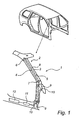
- Fig. 1 shows a part of a vehicle frame structure 1 having an A-pillar 2.
- the A-pillar has an interior cavity 3, in this case in the form of an elongated section, adapted to receive at least one inflatable reinforcement element 4 according to a first embodiment of the invention.
- the cavity is defined by cavity wall portions 5 in which the tubular element is received.
- the element 4 is preferably a tubular element 4 which is fastened in a first end portion 6 and a second end portion 7 of the cavity 3. However, at least one end of the tubular element 4 may extend outside the cavity 3. Additional tubular elements may be arranged in the vehicle at different locations, as exemplified in fig 1 .
- the tubular element 4 in fig. 1 is preferably adapted to reinforce the frame structure 1 in the longitudinal direction between the first end portion 6 and second end portion 7.
- the tubular element 4 in fig. 1 has an essentially circular cross section having a flexible wall portion 8 in an un-active and unpressurized state.
- the wall portion 8 is preferably rigid to such an extent that the element will not be bend and doubled when mounting the element. Preferably, slighter adjustments may be made for easier introduction into the cavity, when mounting the element.
- the tubular element 4 is in fluid connection with a gas generator 9 for pressurizing the element in an active state.
- the gas generation may be achieved in different ways.
- the gas may be generated from gas chambers filled with compressed gases.
- the gases may be: inert gases, such as at least one of the gases; Ar, He or N2 or combustible gases such as one of the gases H2, CH4, C2H6 or C3H8; or any mixtures thereof.
- the gas may be generated from pyrotechnic charges.
- pyrotechnic cords (not shown) may be arranged interiorly the tubular element 4 for pressurization.
- the tubular element preferably comprises a reinforcement material.
- the pressure is preferably above 5 bar and preferably between 5-100 bar, more preferably between 20-70 bar and most preferably between 30-50 bar.
- a ventilation arrangement (not shown) may be arranged in connection with the tubular element.
- the ventilation arrangement may be a burst disc adapted to burst at a predetermined gas pressure or alternatively a mechanical valve which for instance may be spring biased.
- the tubular element may comprise an armoured polymer tube or a metal mantle.
- the reinforcement material may be of different material, designs and forms, such as one of a cord, sheet, fibre, net, weave material portion or a combination thereof.
- the tubular element may comprise one of the following reinforcement layers; glass fibre, metal net, thin steel sheet material or metal cord material. Additionally the tubular element may comprise at least two layers for improving reinforcement or self-stiffening properties.
- Fig. 1 shows that the gas generator 9 may be fitted with an initiator 10 which is connected to a control unit 11, such as an electrical processing unit (EPU) for activating the pressurization in the tubular element.
- the control unit 11 may in turn and alternatively instead be connected to a pre-crash system 12.
- the pre-crash system 12 may comprise a set of sensors arranged at different locations at the vehicle in order to determine which type of crash the vehicle is about to be subjected to.
- sensors may be at least one of the following; a distance sensor, a decelerate sensor and a radar device.
- Fig. 2a shows an alternative reinforcement element 24 according to a second embodiment of the invention to achieve an essentially diagonal reinforcement.
- the tubular element 24 is preferably zigzag shaped but other forms may be used such as an helical shape.
- the dotted line in fig. 2a shows a main centre line along the length extension, wherein the tubular element has transverse extensions 25 directed transversely the main centre line.
- the transverse extensions 25 is preferably slightly bevelled for achieving a smooth contact with the cavity wall 5 and improving the reinforcement characteristics.
- the transverse extensions 25 withstand stresses in the longitudinal direction of the wall portions 8 which are diverging according to the second embodiment.
- the form of the tubular element in relation to the vehicle structure may provide a selected load take-up and a reinforcement in additional directions, such as a combination of a longitudinal and a transversal direction.
- Fig. 2b shows an alternative reinforcement element 34 according to a third embodiment of the invention to achieve a combination of an essentially longitudinal and a transversal reinforcement.
- the tubular element 34 has transversal extensions in the form of transversal protrusions 30, preferably skeleton shaped.
- the protrusions 30 is essentially orthogonally arranged to the main centreline.
- the protrusions 30 is preferably oppositely arranged to contact the cavity wall 5 for improving the reinforcement characteristics.
- the protrusions may be arranged differently at the tubular element, such as unevenly distributed along the longitudinal and / or circumferential direction.
- the control unit 11 may be activated and the initiator 10 can ignites the gas generant material.
- the gas generator 9 discharges the gas into the tubular element via a gas diffuser (not shown) for pressurization. Due to the reinforcement layer the pressurization may be performed with hardly no significant circumferential expansion.
- the tubular element is pressurized without any substantial size expansion.
- the volume of the tubular element in said pressurized state is preferably less than 100% of the entire volume.
- the volume of the tubular element in said pressurized state is preferably under 90% of the entire cavity volume, more preferably under 75% and most preferably under 50% of the entire cavity volume.
- tubular element may be selected to provide a desired particular reinforcing performance in a certain application.
- the tubular element preferably contacting the cavity wall portion without filling up the entire cavity volume.
- the vehicle frame structure 1 may be provided with a set of tubular elements which elements may be activated in sequence or activated with a predetermined delay.
- a in-crash system may be used in addition or alternatively instead of the pre-crash system.
- the in-crash system is preferably arranged with a sensor system as known in the art.
- gas generating devices other ways are possible of pyrotechnic and non-pyrotechnic solutions with or without premixing chambers. It is also possible to combine different gas generating constructions.
- the cavity 3 may be provided with at least two reinforcement elements which may have different reinforcing properties. Additionally the reinforcement element may be arranged in different beams and profiles.
- a profile may be arranged with a tubular element which is held in place at the profile, for instance by transversal bridging elements which at least partly encircles the circumferential wall portion of the tubular elements.
- a front and / or a rear bumper may be provided with at least one reinforcement element according to the invention.
- the bumber seen as a beam, may be arranged with a set of tubular elements.
- the tubular elements can be activated essentially simultaneously or alternatively a selected set may be activated, for instance in a sequence.
- the set may be arranged in a honeycomb structure for an efficient stress up-taking ability.
- Associated beams to the bumper may also be provided with reinforcement elements.
Landscapes
- Engineering & Computer Science (AREA)
- Chemical & Material Sciences (AREA)
- Combustion & Propulsion (AREA)
- Transportation (AREA)
- Mechanical Engineering (AREA)
- Body Structure For Vehicles (AREA)
- Silver Salt Photography Or Processing Solution Therefor (AREA)
- Signal Processing For Digital Recording And Reproducing (AREA)
- Regulating Braking Force (AREA)
Abstract
Description
- The present invention relates to a vehicle structure arrangement comprising a pressurizable reinforcement element provided in connection with a vehicle structure profile to reinforce said profile.
- The above mentioned arrangement is previously known.
DE 19963068 A1 discloses a gas bag which is being inflated and fills up a vehicle cavity, such as a door cavity, in case of an impact accident, wherein the gas bag follows the internal contour of the cavity. - When designing a vehicle structure a number of contradictory requests have to be considered. The structure should be durable and secure enough to provide good protection for the occupants in case of an accident and at the same time provide a slim design of the vehicle structure having good space efficiency.
- In recent years there has been an increased focus on vehicle safety whereby it is desirable to further improve the safety for the vehicle structure.
- Finally it is desirable to provide a robust, cost effective and reliable high quality arrangement for a vehicle structure.
- The object of the invention is to provide a vehicle structure arrangement which allows improvements in relation to prior-art arrangement in one or more of the above aspects.
- In one aspect of the present invention, a vehicle structure arrangement according to the introduction is further characterised in that the reinforcement element is a tubular element comprising a reinforcement material layer and having a flexible wall portion which tubular element is adapted to be self-stiffened when being in a pressurized active state, wherein the material and dimension of the tubular element wall portion are adapted to withstand actual stresses along longitudinal direction of said wall portion, in said pressurized active state.
- Thus the tubular element is pressurized in response to a crash signal and / or a predicted crash signal to improve the strength of the vehicle structure profile.
- The wall portion of the tubular element is stiffened in such a way that the wall portion can withstand loads in the longitudinal direction of the wall portion. The form of the tubular element with its wall portions may be adapted to a specific crash type, such as when a vehicle turns upside down (roll over). For instance an adapted activation may be performed by selected tubular elements to constitute a reinforcement adapted to the crash type.
- By the expression "self-stiffened" is meant that the tubular element is more stiffened and that the wall portion of tubular element in itself may withstand stresses.
- By the expression "flexible wall portion" is primary meant that that the wall thickness is adapted to withstand significantly higher stresses in a pressurized state. The wall portion may be of a semi-rigid material which may flex to some extent e.g. for easier mounting purposes.
- The vehicle structure profile is a beam, such as a pillar, having an interior space wherein the reinforcement element is arranged at least partly in said interior space of said beam. In such a case the reinforcement element is arranged in a restricted area for up-taking actual stresses and loads. For instance, the beam, may comprise several interior spaces fitted with several reinforcement elements.
- The tubular element is preferably self-stiffened without filling up said interior space of said beam, in said pressurized active state. Thus the entire volume of the interior space is preferably not filled up. Preferably, the tubular element do not follow all the contours of the interior space. For instance the non occupied space may be used by other devices, such as one of a cable, an energy absorbing element and an additional reinforcement element.
- The wall portion of the tubular element may be arranged to contact an opposite wall portion of said beam. In an active state the tubular portion may have at least one contact surface with the interior surface of the beam as an additional reinforcement.
- Preferably, the extension of said tubular element is adapted to the extension of said vehicle structure profile so as to constitute said reinforcement in at least one predetermined direction. For instance, the tubular element may be adapted to said predetermined direction which having at least one of the reinforcements in said pressurized active state; a lengthwise reinforcement, a diagonal reinforcement, a transversal reinforcement and a reinforcement orthogonally the length extension and combinations thereof. Thus, the reinforcement may be adaptive controlled due to the type of crash.
- In order to constitute the reinforcement in specific predetermined directions, the vehicle structure profile may have a main centreline along the length extension, wherein said tubular element having at least a transverse extension which is directed transversely said main centreline.
- By arranging said transverse extension to contact opposite wall portions of said vehicle structure profile, the contact may act as a support point for additional reinforcement in said active state.
- Also, the transverse extension may be at least one protrusion directed transversely a centre portion of said tubular element. In order to perform a lengthwise reinforcement and a transversal reinforcement, the tubular element may be skeleton shaped comprising a number of said protrusions with opposite contact surfaces of the vehicle structure profile.
- In order to perform a diagonal reinforcement, the tubular element is zigzag shaped, having wall portions which extends alternatingly each other with opposite contact surfaces of said vehicle structure profile.
- The tubular element is preferably arranged between a first end portion and a second end portion of said beam. The end portions may be fastening portions for supporting and reinforcing the vehicle structure profile. For instance the fasting portions may be an upper and lower fastening portions for an essentially vertical pillar.
- The tubular element may comprises a reinforcement material layer, such as one of a glass fibre material, thin metal material, carbon fibre material, concatenating polymer material, rowing weave material or combinations thereof. The reinforcement layer may be one of a cord, a sheet, a net or weave material, for instance a metal net or an armoured conduit of polymer material. The reinforcement layer may be a separate layer or may be integrated with the rest of the wall portion material.
- The wall portion of said tubular element may comprises at least two layers for enabling different reinforcement properties or providing a pressurizable intermediate space between the layers.
- According to an embodiment of the invention the vehicle structure profile is a A-pillar and / or a B-pillar for which pillars reinforcement as well as space efficiency are important aspects. Alternatively other parts of the vehicle may be reinforced, for instance the vehicle structure profile may be a front bumper and / or a rear bumper.
- The vehicle structure profile may comprise at least two tubular elements arranged to be independently pressurized. Such an arrangement enables a further adapted reinforcement. The tubular elements may be arranged with one or several pressurizing means. For instance the tubular element may be pressurized in sequence or respectively pressurized with a predetermined time delay. Also the tubular element may have different or complementary reinforcing properties.
- The reinforcement element may be adapted to be selectively activated, due to the type of impact.
- For instance the vehicle may comprises a pre-crash system in connection with one or several tubular elements. Based on the predicted crash type in the pre-crash system, an adaptively activation may be performed by selected tubular elements for reinforcement in at least one predetermined direction. For instance the selection may be regulated by valves in connection with the pressurisation of the selected elements.
- Objects and advantages will be apparent to those skilled in the art form the following detailed description taken in conjunction with the appended claims and drawings.
- The present invention will now be described in more detail with the reference to the accompanying schematic drawings which show preferred embodiments of the invention and in which:
-
Fig. 1 shows a perspective view, partly in section, of a pillar fitted with a reinforcement element according to a first embodiment of the invention. -
Fig. 2a shows a perspective view of a reinforcement element according to a second embodiment of the invention. -
Fig. 2b shows a perspective view of a reinforcement element according to a third embodiment of the invention. -
Fig. 1 shows a part of avehicle frame structure 1 having anA-pillar 2. The A-pillar has aninterior cavity 3, in this case in the form of an elongated section, adapted to receive at least oneinflatable reinforcement element 4 according to a first embodiment of the invention. The cavity is defined bycavity wall portions 5 in which the tubular element is received. Theelement 4 is preferably atubular element 4 which is fastened in afirst end portion 6 and a second end portion 7 of thecavity 3. However, at least one end of thetubular element 4 may extend outside thecavity 3. Additional tubular elements may be arranged in the vehicle at different locations, as exemplified infig 1 . - The
tubular element 4 infig. 1 is preferably adapted to reinforce theframe structure 1 in the longitudinal direction between thefirst end portion 6 and second end portion 7. Thetubular element 4 infig. 1 has an essentially circular cross section having aflexible wall portion 8 in an un-active and unpressurized state. Thewall portion 8 is preferably rigid to such an extent that the element will not be bend and doubled when mounting the element. Preferably, slighter adjustments may be made for easier introduction into the cavity, when mounting the element. - The
tubular element 4 is in fluid connection with a gas generator 9 for pressurizing the element in an active state. The gas generation may be achieved in different ways. The gas may be generated from gas chambers filled with compressed gases. The gases may be: inert gases, such as at least one of the gases; Ar, He or N2 or combustible gases such as one of the gases H2, CH4, C2H6 or C3H8; or any mixtures thereof. Alternatively the gas may be generated from pyrotechnic charges. For instance pyrotechnic cords (not shown) may be arranged interiorly thetubular element 4 for pressurization. - Due to the high pressure in the active state, the tubular element preferably comprises a reinforcement material. The pressure is preferably above 5 bar and preferably between 5-100 bar, more preferably between 20-70 bar and most preferably between 30-50 bar.
- To ventilate the tubular element from excess of gas and to regulate the gas pressure a ventilation arrangement (not shown) may be arranged in connection with the tubular element. The ventilation arrangement may be a burst disc adapted to burst at a predetermined gas pressure or alternatively a mechanical valve which for instance may be spring biased.
- The tubular element may comprise an armoured polymer tube or a metal mantle.
- However, the reinforcement material may be of different material, designs and forms, such as one of a cord, sheet, fibre, net, weave material portion or a combination thereof. For instance the tubular element may comprise one of the following reinforcement layers; glass fibre, metal net, thin steel sheet material or metal cord material. Additionally the tubular element may comprise at least two layers for improving reinforcement or self-stiffening properties.
-
Fig. 1 shows that the gas generator 9 may be fitted with aninitiator 10 which is connected to acontrol unit 11, such as an electrical processing unit (EPU) for activating the pressurization in the tubular element. Thecontrol unit 11 may in turn and alternatively instead be connected to apre-crash system 12. Thepre-crash system 12 may comprise a set of sensors arranged at different locations at the vehicle in order to determine which type of crash the vehicle is about to be subjected to. As an example such sensors may be at least one of the following; a distance sensor, a decelerate sensor and a radar device. -
Fig. 2a shows analternative reinforcement element 24 according to a second embodiment of the invention to achieve an essentially diagonal reinforcement. Thetubular element 24 is preferably zigzag shaped but other forms may be used such as an helical shape. The dotted line infig. 2a shows a main centre line along the length extension, wherein the tubular element hastransverse extensions 25 directed transversely the main centre line. Thetransverse extensions 25 is preferably slightly bevelled for achieving a smooth contact with thecavity wall 5 and improving the reinforcement characteristics. Thetransverse extensions 25 withstand stresses in the longitudinal direction of thewall portions 8 which are diverging according to the second embodiment. Thus, the form of the tubular element in relation to the vehicle structure may provide a selected load take-up and a reinforcement in additional directions, such as a combination of a longitudinal and a transversal direction. -
Fig. 2b shows analternative reinforcement element 34 according to a third embodiment of the invention to achieve a combination of an essentially longitudinal and a transversal reinforcement. Thetubular element 34 has transversal extensions in the form oftransversal protrusions 30, preferably skeleton shaped. In this case theprotrusions 30 is essentially orthogonally arranged to the main centreline. Theprotrusions 30 is preferably oppositely arranged to contact thecavity wall 5 for improving the reinforcement characteristics. However the protrusions may be arranged differently at the tubular element, such as unevenly distributed along the longitudinal and / or circumferential direction. - With reference to
fig. 1 the function of the arrangement according to the invention will be described in the following. - Upon sensing a crash in the absolute near future by the
pre-crash system 12 thecontrol unit 11 may be activated and theinitiator 10 can ignites the gas generant material. The gas generator 9 discharges the gas into the tubular element via a gas diffuser (not shown) for pressurization. Due to the reinforcement layer the pressurization may be performed with hardly no significant circumferential expansion. Preferably the tubular element is pressurized without any substantial size expansion. In order to be more space efficient, the volume of the tubular element in said pressurized state is preferably less than 100% of the entire volume. Preferably the volume of the tubular element in said pressurized state is preferably under 90% of the entire cavity volume, more preferably under 75% and most preferably under 50% of the entire cavity volume. However, the number, the form and positioning of tubular element may be selected to provide a desired particular reinforcing performance in a certain application. For instance the tubular element preferably contacting the cavity wall portion without filling up the entire cavity volume. Additionally, as shown infig. 1 , thevehicle frame structure 1 may be provided with a set of tubular elements which elements may be activated in sequence or activated with a predetermined delay. - It will be appreciated that the above-described embodiments of the invention can be modified and varied by a person skilled in the art without departing from the inventive concept defined in the claims. For instance a in-crash system may be used in addition or alternatively instead of the pre-crash system. The in-crash system is preferably arranged with a sensor system as known in the art. In addition to the already mentioned gas generating devices, other ways are possible of pyrotechnic and non-pyrotechnic solutions with or without premixing chambers. It is also possible to combine different gas generating constructions. Also, the
cavity 3 may be provided with at least two reinforcement elements which may have different reinforcing properties. Additionally the reinforcement element may be arranged in different beams and profiles. For instance a profile may be arranged with a tubular element which is held in place at the profile, for instance by transversal bridging elements which at least partly encircles the circumferential wall portion of the tubular elements. Also a front and / or a rear bumper may be provided with at least one reinforcement element according to the invention. For instance, the bumber, seen as a beam, may be arranged with a set of tubular elements. The tubular elements can be activated essentially simultaneously or alternatively a selected set may be activated, for instance in a sequence. The set may be arranged in a honeycomb structure for an efficient stress up-taking ability. Associated beams to the bumper may also be provided with reinforcement elements.
Claims (13)
- Vehicle structure arrangement comprising a pressurizable reinforcement element (4; 24; 34) provided in connection with a vehicle structure profile (2) to reinforce said profile, wherein the reinforcement element (4; 24; 34) is adapted to be selectively activated, due to the type of impact, and wherein said vehicle structure profile is a beam and has an interior space and the reinforcement element (4; 24; 34) is arranged at least partly in said interior space (3) of said beam
characterised in that the reinforcement element is a tubular element (4; 24; 34) comprising a reinforcement material layer and having a flexible wall portion (8), which tubular element is adapted to be self-stiffened when being in a pressurized active state, wherein the material and dimension of the tubular element wall portion (8) are adapted to withstand actual stresses along longitudinal direction of said wall portion (8), in said pressurized active state. - The arrangement according to claim 1, wherein said vehicle structure profile is a pillar.
- The arrangement according to claim 2, wherein said tubular element (4; 24; 34) is self-stiffened without filling up said interior space (3) of said beam, in said pressurized active state.
- The arrangement according to claim 3, wherein said wall portion (8) of the tubular element (4; 24; 34) is arranged to contact opposite wall portions (5) of said beam (2).
- The arrangement according to any of the preceding claims, wherein the extension of said tubular element (4; 24; 34) is adapted to the extension of said vehicle structure profile (2) so as to constitute said reinforcement in at least one predetermined direction.
- The arrangement according to claim 5, wherein said tubular element is adapted to said predetermined direction having at least one of the reinforcements in said pressurized active state; a lengthwise reinforcement, a diagonal reinforcement, a transversal reinforcement and a reinforcement orthogonally the length extension.
- The arrangement according to any of the preceding claims, wherein said vehicle structure profile having a main centreline along the length extension, wherein said tubular element (24; 34) having at least a transverse extension (25; 30) which is directed transversely said main centreline.
- The arrangement according to any of the preceding claims, wherein said tubular element (4; 24; 34) is arranged between a first end portion (6) and a second end portion (7) of said beam (2).
- The arrangement according to any of the preceding claims, wherein said reinforcement material layer is one of a glass fibre material, thin metal material, carbon fibre material, concatenating polymer material, rowing weave material or combinations thereof.
- The arrangement according to any of the preceding claims, wherein said wall portion (8) of said tubular element (4; 24; 34) comprises at least two layers.
- The arrangement according to any of the preceding claims, wherein said vehicle structure profile (2) is an A-pillar and / or a B-pillar.
- The arrangement according to any of the claims 1-10, wherein said vehicle structure profile is a front bumper and / or a rear bumper.
- The arrangement according to any of the preceding claims, wherein said vehicle structure profile comprises at least two tubular elements (4; 24; 34) arranged to be independently pressurized.
Applications Claiming Priority (1)
| Application Number | Priority Date | Filing Date | Title |
|---|---|---|---|
| PCT/SE2006/000700 WO2007145547A1 (en) | 2006-06-14 | 2006-06-14 | Vehicle structure arrangement provided with pressurizable reinforcement element |
Publications (2)
| Publication Number | Publication Date |
|---|---|
| EP2027006A1 EP2027006A1 (en) | 2009-02-25 |
| EP2027006B1 true EP2027006B1 (en) | 2010-02-03 |
Family
ID=38831971
Family Applications (1)
| Application Number | Title | Priority Date | Filing Date |
|---|---|---|---|
| EP06747893A Not-in-force EP2027006B1 (en) | 2006-06-14 | 2006-06-14 | Vehicle structure arrangement provided with pressurizable reinforcement element |
Country Status (6)
| Country | Link |
|---|---|
| US (1) | US8215674B2 (en) |
| EP (1) | EP2027006B1 (en) |
| JP (1) | JP2009539698A (en) |
| AT (1) | ATE457005T1 (en) |
| DE (1) | DE602006012128D1 (en) |
| WO (1) | WO2007145547A1 (en) |
Cited By (1)
| Publication number | Priority date | Publication date | Assignee | Title |
|---|---|---|---|---|
| DE102016122873A1 (en) * | 2016-11-28 | 2018-05-30 | Dr. Ing. H.C. F. Porsche Aktiengesellschaft | positioning |
Families Citing this family (10)
| Publication number | Priority date | Publication date | Assignee | Title |
|---|---|---|---|---|
| US8256829B2 (en) * | 2004-04-02 | 2012-09-04 | GM Global Technology Operations LLC | Active material inserts for use with hollow structures |
| US8733819B1 (en) | 2013-01-22 | 2014-05-27 | Ford Global Technologies, Llc | Variable stiffness energy-absorbing component for vehicle occupant protection |
| US9731768B2 (en) * | 2015-03-27 | 2017-08-15 | Ford Global Technologies, Llc | Vehicle structural reinforcing device |
| DE102017200368A1 (en) * | 2017-01-11 | 2018-07-12 | Bayerische Motoren Werke Aktiengesellschaft | Bow of a motor vehicle |
| JP6805999B2 (en) * | 2017-08-10 | 2020-12-23 | 豊田合成株式会社 | Variable rigidity structure of vehicle support |
| US20190071050A1 (en) * | 2017-09-06 | 2019-03-07 | Ford Global Technologies, Llc | Vehicle airbag system |
| JP6927058B2 (en) | 2018-01-18 | 2021-08-25 | トヨタ自動車株式会社 | Vehicle seat |
| JP6927059B2 (en) | 2018-01-18 | 2021-08-25 | トヨタ自動車株式会社 | Vehicle seat |
| JP6921137B2 (en) * | 2019-03-11 | 2021-08-18 | 本田技研工業株式会社 | Vehicle front structure |
| US11136065B2 (en) * | 2020-02-24 | 2021-10-05 | Ford Global Technologies, Llc | Extended roof reinforcement structure |
Family Cites Families (15)
| Publication number | Priority date | Publication date | Assignee | Title |
|---|---|---|---|---|
| DE2364300A1 (en) * | 1973-12-22 | 1975-06-26 | Porsche Ag | DEVICE FOR ENERGY ABSORPTION FOR VEHICLES, IN PARTICULAR MOTOR VEHICLES |
| US5382051A (en) * | 1991-08-28 | 1995-01-17 | Concept Analysis Corporation | Pneumatic pads for the interior of vehicles |
| US5727815A (en) * | 1996-02-09 | 1998-03-17 | Morton International, Inc. | Stiffening system for structural member of motor vehicle frame |
| US5845937A (en) * | 1997-02-10 | 1998-12-08 | Morton International, Inc. | Structural assembly |
| WO2000002751A1 (en) * | 1998-07-09 | 2000-01-20 | Giat Industries | Bumper equipped with shock absorbing means |
| US6113178A (en) * | 1998-08-31 | 2000-09-05 | Trw Vehicle Safety Systems Inc. | Vehicle energy absorption apparatus |
| JP3496751B2 (en) * | 1999-01-29 | 2004-02-16 | マツダ株式会社 | Car body structure |
| GB2354979A (en) * | 1999-10-09 | 2001-04-11 | Ford Global Tech Inc | Collapsible vehicle side members having airbags within |
| DE19963068C5 (en) | 1999-12-24 | 2011-05-12 | Dr. Ing. H.C. F. Porsche Aktiengesellschaft | Device for impact-deformation energy-transforming-deformable body parts of motor vehicles |
| US20020175537A1 (en) * | 2001-04-02 | 2002-11-28 | Cress Steven B. | Vehicle strengthening method and apparatus |
| JP4306229B2 (en) * | 2002-04-03 | 2009-07-29 | タカタ株式会社 | Collision detection device and safety device |
| JP2005035403A (en) * | 2003-07-15 | 2005-02-10 | Toyota Motor Corp | Impact- resistant structure for vehicle |
| US7232002B2 (en) * | 2003-07-18 | 2007-06-19 | University Of Washington | Apparatus for controlling rigidity of vehicle body |
| GB2422645B (en) * | 2005-02-01 | 2009-05-13 | Autoliv Dev | Improvements in or relating to a safety arrangement |
| KR101033790B1 (en) * | 2008-12-04 | 2011-05-13 | 기아자동차주식회사 | External air-bag system for a vehicle |
-
2006
- 2006-06-14 DE DE602006012128T patent/DE602006012128D1/en active Active
- 2006-06-14 JP JP2009515330A patent/JP2009539698A/en active Pending
- 2006-06-14 EP EP06747893A patent/EP2027006B1/en not_active Not-in-force
- 2006-06-14 AT AT06747893T patent/ATE457005T1/en not_active IP Right Cessation
- 2006-06-14 US US12/304,199 patent/US8215674B2/en not_active Expired - Fee Related
- 2006-06-14 WO PCT/SE2006/000700 patent/WO2007145547A1/en active Application Filing
Cited By (1)
| Publication number | Priority date | Publication date | Assignee | Title |
|---|---|---|---|---|
| DE102016122873A1 (en) * | 2016-11-28 | 2018-05-30 | Dr. Ing. H.C. F. Porsche Aktiengesellschaft | positioning |
Also Published As
| Publication number | Publication date |
|---|---|
| DE602006012128D1 (en) | 2010-03-25 |
| WO2007145547A1 (en) | 2007-12-21 |
| ATE457005T1 (en) | 2010-02-15 |
| US20090267386A1 (en) | 2009-10-29 |
| JP2009539698A (en) | 2009-11-19 |
| US8215674B2 (en) | 2012-07-10 |
| EP2027006A1 (en) | 2009-02-25 |
Similar Documents
| Publication | Publication Date | Title |
|---|---|---|
| EP2027006B1 (en) | Vehicle structure arrangement provided with pressurizable reinforcement element | |
| KR100256432B1 (en) | Side impact passenger strike protection device and method | |
| CN102099227B (en) | Vehicle seat arrangement and airbag arrangement for motor vehicle and method for protecting a vehicle occupant | |
| KR101829678B1 (en) | Energy absorption system | |
| CN101790468A (en) | Structure for a vehicle seat | |
| US7261345B2 (en) | Impact energy absorbing crash cushion | |
| US7497504B2 (en) | Side-on collision beam for a motor vehicle | |
| EP0688702A2 (en) | Inflatable tubular cushions for crash protection of seated automobile occupants | |
| US20100276918A1 (en) | Support Structure for an Airbag | |
| US4664438A (en) | Deformable berth for vehicle cabs | |
| US7322601B2 (en) | Resiliently compressible deployment ramp for inflatable curtain | |
| KR20080006539A (en) | Device for protecting passengers in a motor vehicle in the event of an energy input caused by a collision and oriented towards a motor vehicle door | |
| US7441832B2 (en) | Pneumatically reinforced vehicle body structure | |
| US7458608B2 (en) | Vehicle rollover protection system with a roll bar, whose top piece is rounded in U-shape | |
| EP1951557B1 (en) | Safety system | |
| CN114375266A (en) | Vehicle bumper extension with crush box bracket | |
| CN107000669B (en) | Occupant restraint system for a vehicle | |
| US20030197358A1 (en) | Air bag module assembly | |
| KR20090017578A (en) | Vehicle structure arrangement provided with pressurizable reinforcement element | |
| JP2005035403A (en) | Impact- resistant structure for vehicle | |
| US20060208467A1 (en) | Head impact energy-absorbing inflatable curtain gas delivery tube | |
| US20040100081A1 (en) | Passive protection device and vehicle equipped therewith | |
| US20070132221A1 (en) | Energy absorbing fill tube for a side car curtain system | |
| KR100971543B1 (en) | High pressure tube used for a frame | |
| KR100507639B1 (en) | Impact absorption structure of automobile front side member |
Legal Events
| Date | Code | Title | Description |
|---|---|---|---|
| PUAI | Public reference made under article 153(3) epc to a published international application that has entered the european phase |
Free format text: ORIGINAL CODE: 0009012 |
|
| 17P | Request for examination filed |
Effective date: 20081117 |
|
| AK | Designated contracting states |
Kind code of ref document: A1 Designated state(s): AT BE BG CH CY CZ DE DK EE ES FI FR GB GR HU IE IS IT LI LT LU LV MC NL PL PT RO SE SI SK TR |
|
| AX | Request for extension of the european patent |
Extension state: AL BA HR MK RS |
|
| RIN1 | Information on inventor provided before grant (corrected) |
Inventor name: PERSSON, DAN |
|
| RIC1 | Information provided on ipc code assigned before grant |
Ipc: B62D 21/16 20060101ALI20090519BHEP Ipc: B60R 19/18 20060101ALI20090519BHEP Ipc: B62D 21/15 20060101AFI20080228BHEP Ipc: B62D 25/04 20060101ALI20090519BHEP |
|
| 17Q | First examination report despatched |
Effective date: 20090715 |
|
| GRAP | Despatch of communication of intention to grant a patent |
Free format text: ORIGINAL CODE: EPIDOSNIGR1 |
|
| DAX | Request for extension of the european patent (deleted) | ||
| GRAS | Grant fee paid |
Free format text: ORIGINAL CODE: EPIDOSNIGR3 |
|
| GRAA | (expected) grant |
Free format text: ORIGINAL CODE: 0009210 |
|
| AK | Designated contracting states |
Kind code of ref document: B1 Designated state(s): AT BE BG CH CY CZ DE DK EE ES FI FR GB GR HU IE IS IT LI LT LU LV MC NL PL PT RO SE SI SK TR |
|
| REG | Reference to a national code |
Ref country code: GB Ref legal event code: FG4D |
|
| REG | Reference to a national code |
Ref country code: CH Ref legal event code: EP |
|
| REG | Reference to a national code |
Ref country code: IE Ref legal event code: FG4D |
|
| REF | Corresponds to: |
Ref document number: 602006012128 Country of ref document: DE Date of ref document: 20100325 Kind code of ref document: P |
|
| REG | Reference to a national code |
Ref country code: NL Ref legal event code: VDEP Effective date: 20100203 |
|
| LTIE | Lt: invalidation of european patent or patent extension |
Effective date: 20100203 |
|
| PG25 | Lapsed in a contracting state [announced via postgrant information from national office to epo] |
Ref country code: IS Free format text: LAPSE BECAUSE OF FAILURE TO SUBMIT A TRANSLATION OF THE DESCRIPTION OR TO PAY THE FEE WITHIN THE PRESCRIBED TIME-LIMIT Effective date: 20100603 Ref country code: LT Free format text: LAPSE BECAUSE OF FAILURE TO SUBMIT A TRANSLATION OF THE DESCRIPTION OR TO PAY THE FEE WITHIN THE PRESCRIBED TIME-LIMIT Effective date: 20100203 Ref country code: ES Free format text: LAPSE BECAUSE OF FAILURE TO SUBMIT A TRANSLATION OF THE DESCRIPTION OR TO PAY THE FEE WITHIN THE PRESCRIBED TIME-LIMIT Effective date: 20100514 Ref country code: PT Free format text: LAPSE BECAUSE OF FAILURE TO SUBMIT A TRANSLATION OF THE DESCRIPTION OR TO PAY THE FEE WITHIN THE PRESCRIBED TIME-LIMIT Effective date: 20100603 |
|
| PG25 | Lapsed in a contracting state [announced via postgrant information from national office to epo] |
Ref country code: PL Free format text: LAPSE BECAUSE OF FAILURE TO SUBMIT A TRANSLATION OF THE DESCRIPTION OR TO PAY THE FEE WITHIN THE PRESCRIBED TIME-LIMIT Effective date: 20100203 Ref country code: LV Free format text: LAPSE BECAUSE OF FAILURE TO SUBMIT A TRANSLATION OF THE DESCRIPTION OR TO PAY THE FEE WITHIN THE PRESCRIBED TIME-LIMIT Effective date: 20100203 Ref country code: AT Free format text: LAPSE BECAUSE OF FAILURE TO SUBMIT A TRANSLATION OF THE DESCRIPTION OR TO PAY THE FEE WITHIN THE PRESCRIBED TIME-LIMIT Effective date: 20100203 Ref country code: SI Free format text: LAPSE BECAUSE OF FAILURE TO SUBMIT A TRANSLATION OF THE DESCRIPTION OR TO PAY THE FEE WITHIN THE PRESCRIBED TIME-LIMIT Effective date: 20100203 Ref country code: FI Free format text: LAPSE BECAUSE OF FAILURE TO SUBMIT A TRANSLATION OF THE DESCRIPTION OR TO PAY THE FEE WITHIN THE PRESCRIBED TIME-LIMIT Effective date: 20100203 |
|
| PG25 | Lapsed in a contracting state [announced via postgrant information from national office to epo] |
Ref country code: GR Free format text: LAPSE BECAUSE OF FAILURE TO SUBMIT A TRANSLATION OF THE DESCRIPTION OR TO PAY THE FEE WITHIN THE PRESCRIBED TIME-LIMIT Effective date: 20100504 Ref country code: NL Free format text: LAPSE BECAUSE OF FAILURE TO SUBMIT A TRANSLATION OF THE DESCRIPTION OR TO PAY THE FEE WITHIN THE PRESCRIBED TIME-LIMIT Effective date: 20100203 Ref country code: SE Free format text: LAPSE BECAUSE OF FAILURE TO SUBMIT A TRANSLATION OF THE DESCRIPTION OR TO PAY THE FEE WITHIN THE PRESCRIBED TIME-LIMIT Effective date: 20100203 Ref country code: RO Free format text: LAPSE BECAUSE OF FAILURE TO SUBMIT A TRANSLATION OF THE DESCRIPTION OR TO PAY THE FEE WITHIN THE PRESCRIBED TIME-LIMIT Effective date: 20100203 Ref country code: CY Free format text: LAPSE BECAUSE OF FAILURE TO SUBMIT A TRANSLATION OF THE DESCRIPTION OR TO PAY THE FEE WITHIN THE PRESCRIBED TIME-LIMIT Effective date: 20100203 Ref country code: EE Free format text: LAPSE BECAUSE OF FAILURE TO SUBMIT A TRANSLATION OF THE DESCRIPTION OR TO PAY THE FEE WITHIN THE PRESCRIBED TIME-LIMIT Effective date: 20100203 Ref country code: BE Free format text: LAPSE BECAUSE OF FAILURE TO SUBMIT A TRANSLATION OF THE DESCRIPTION OR TO PAY THE FEE WITHIN THE PRESCRIBED TIME-LIMIT Effective date: 20100203 |
|
| PG25 | Lapsed in a contracting state [announced via postgrant information from national office to epo] |
Ref country code: CZ Free format text: LAPSE BECAUSE OF FAILURE TO SUBMIT A TRANSLATION OF THE DESCRIPTION OR TO PAY THE FEE WITHIN THE PRESCRIBED TIME-LIMIT Effective date: 20100203 Ref country code: BG Free format text: LAPSE BECAUSE OF FAILURE TO SUBMIT A TRANSLATION OF THE DESCRIPTION OR TO PAY THE FEE WITHIN THE PRESCRIBED TIME-LIMIT Effective date: 20100503 Ref country code: SK Free format text: LAPSE BECAUSE OF FAILURE TO SUBMIT A TRANSLATION OF THE DESCRIPTION OR TO PAY THE FEE WITHIN THE PRESCRIBED TIME-LIMIT Effective date: 20100203 |
|
| PLBE | No opposition filed within time limit |
Free format text: ORIGINAL CODE: 0009261 |
|
| STAA | Information on the status of an ep patent application or granted ep patent |
Free format text: STATUS: NO OPPOSITION FILED WITHIN TIME LIMIT |
|
| 26N | No opposition filed |
Effective date: 20101104 |
|
| PG25 | Lapsed in a contracting state [announced via postgrant information from national office to epo] |
Ref country code: DK Free format text: LAPSE BECAUSE OF FAILURE TO SUBMIT A TRANSLATION OF THE DESCRIPTION OR TO PAY THE FEE WITHIN THE PRESCRIBED TIME-LIMIT Effective date: 20100203 Ref country code: MC Free format text: LAPSE BECAUSE OF NON-PAYMENT OF DUE FEES Effective date: 20100630 |
|
| REG | Reference to a national code |
Ref country code: CH Ref legal event code: PL |
|
| GBPC | Gb: european patent ceased through non-payment of renewal fee |
Effective date: 20100614 |
|
| PG25 | Lapsed in a contracting state [announced via postgrant information from national office to epo] |
Ref country code: IT Free format text: LAPSE BECAUSE OF FAILURE TO SUBMIT A TRANSLATION OF THE DESCRIPTION OR TO PAY THE FEE WITHIN THE PRESCRIBED TIME-LIMIT Effective date: 20100203 |
|
| PG25 | Lapsed in a contracting state [announced via postgrant information from national office to epo] |
Ref country code: LI Free format text: LAPSE BECAUSE OF NON-PAYMENT OF DUE FEES Effective date: 20100630 Ref country code: CH Free format text: LAPSE BECAUSE OF NON-PAYMENT OF DUE FEES Effective date: 20100630 Ref country code: IE Free format text: LAPSE BECAUSE OF NON-PAYMENT OF DUE FEES Effective date: 20100614 |
|
| PG25 | Lapsed in a contracting state [announced via postgrant information from national office to epo] |
Ref country code: GB Free format text: LAPSE BECAUSE OF NON-PAYMENT OF DUE FEES Effective date: 20100614 |
|
| PG25 | Lapsed in a contracting state [announced via postgrant information from national office to epo] |
Ref country code: HU Free format text: LAPSE BECAUSE OF FAILURE TO SUBMIT A TRANSLATION OF THE DESCRIPTION OR TO PAY THE FEE WITHIN THE PRESCRIBED TIME-LIMIT Effective date: 20100804 Ref country code: LU Free format text: LAPSE BECAUSE OF NON-PAYMENT OF DUE FEES Effective date: 20100614 |
|
| PG25 | Lapsed in a contracting state [announced via postgrant information from national office to epo] |
Ref country code: TR Free format text: LAPSE BECAUSE OF FAILURE TO SUBMIT A TRANSLATION OF THE DESCRIPTION OR TO PAY THE FEE WITHIN THE PRESCRIBED TIME-LIMIT Effective date: 20100203 |
|
| REG | Reference to a national code |
Ref country code: FR Ref legal event code: PLFP Year of fee payment: 10 |
|
| PGFP | Annual fee paid to national office [announced via postgrant information from national office to epo] |
Ref country code: DE Payment date: 20150413 Year of fee payment: 10 |
|
| PGFP | Annual fee paid to national office [announced via postgrant information from national office to epo] |
Ref country code: FR Payment date: 20150406 Year of fee payment: 10 |
|
| REG | Reference to a national code |
Ref country code: DE Ref legal event code: R119 Ref document number: 602006012128 Country of ref document: DE |
|
| REG | Reference to a national code |
Ref country code: FR Ref legal event code: ST Effective date: 20170228 |
|
| PG25 | Lapsed in a contracting state [announced via postgrant information from national office to epo] |
Ref country code: FR Free format text: LAPSE BECAUSE OF NON-PAYMENT OF DUE FEES Effective date: 20160630 Ref country code: DE Free format text: LAPSE BECAUSE OF NON-PAYMENT OF DUE FEES Effective date: 20170103 |