EP2026414A1 - Module connector - Google Patents
Module connector Download PDFInfo
- Publication number
- EP2026414A1 EP2026414A1 EP08010911A EP08010911A EP2026414A1 EP 2026414 A1 EP2026414 A1 EP 2026414A1 EP 08010911 A EP08010911 A EP 08010911A EP 08010911 A EP08010911 A EP 08010911A EP 2026414 A1 EP2026414 A1 EP 2026414A1
- Authority
- EP
- European Patent Office
- Prior art keywords
- container
- parts
- module
- connector
- camera module
- Prior art date
- Legal status (The legal status is an assumption and is not a legal conclusion. Google has not performed a legal analysis and makes no representation as to the accuracy of the status listed.)
- Granted
Links
Images



Classifications
-
- H—ELECTRICITY
- H01—ELECTRIC ELEMENTS
- H01R—ELECTRICALLY-CONDUCTIVE CONNECTIONS; STRUCTURAL ASSOCIATIONS OF A PLURALITY OF MUTUALLY-INSULATED ELECTRICAL CONNECTING ELEMENTS; COUPLING DEVICES; CURRENT COLLECTORS
- H01R12/00—Structural associations of a plurality of mutually-insulated electrical connecting elements, specially adapted for printed circuits, e.g. printed circuit boards [PCB], flat or ribbon cables, or like generally planar structures, e.g. terminal strips, terminal blocks; Coupling devices specially adapted for printed circuits, flat or ribbon cables, or like generally planar structures; Terminals specially adapted for contact with, or insertion into, printed circuits, flat or ribbon cables, or like generally planar structures
- H01R12/70—Coupling devices
- H01R12/7076—Coupling devices for connection between PCB and component, e.g. display
-
- H—ELECTRICITY
- H01—ELECTRIC ELEMENTS
- H01R—ELECTRICALLY-CONDUCTIVE CONNECTIONS; STRUCTURAL ASSOCIATIONS OF A PLURALITY OF MUTUALLY-INSULATED ELECTRICAL CONNECTING ELEMENTS; COUPLING DEVICES; CURRENT COLLECTORS
- H01R12/00—Structural associations of a plurality of mutually-insulated electrical connecting elements, specially adapted for printed circuits, e.g. printed circuit boards [PCB], flat or ribbon cables, or like generally planar structures, e.g. terminal strips, terminal blocks; Coupling devices specially adapted for printed circuits, flat or ribbon cables, or like generally planar structures; Terminals specially adapted for contact with, or insertion into, printed circuits, flat or ribbon cables, or like generally planar structures
- H01R12/70—Coupling devices
- H01R12/71—Coupling devices for rigid printing circuits or like structures
- H01R12/712—Coupling devices for rigid printing circuits or like structures co-operating with the surface of the printed circuit or with a coupling device exclusively provided on the surface of the printed circuit
- H01R12/716—Coupling device provided on the PCB
-
- H—ELECTRICITY
- H01—ELECTRIC ELEMENTS
- H01R—ELECTRICALLY-CONDUCTIVE CONNECTIONS; STRUCTURAL ASSOCIATIONS OF A PLURALITY OF MUTUALLY-INSULATED ELECTRICAL CONNECTING ELEMENTS; COUPLING DEVICES; CURRENT COLLECTORS
- H01R2201/00—Connectors or connections adapted for particular applications
- H01R2201/16—Connectors or connections adapted for particular applications for telephony
Definitions
- the present invention relates to a module connector to which a module such as a camera module with a solid state image sensor is connected.
- a connector that connects with a module which is an electronic component such as a camera module, has a spring hook that projects toward the interior of the container, which accommodates the module, to prevent the module in the container from falling.
- FIG.1 and FIG. 2 illustrate a conventional connector.
- FIG.1 is a schematic longitudinal cross-sectional view showing a connector, illustrating the configuration of the conventional connector and a module mounted in the connector.
- FIG.2 is a schematic cross-sectional view showing a state where the module is attached to the connector shown in FIG.1 .
- Connector 10 shown in FIG.1 and FIG.2 attaches built-in module 20 to the equipment.
- Module 20 is a camera module mounted in, for example, mobile telephones, and has lens part 24 above module body 23 which is approximately a quadrilateral and has substrate 21 in the bottom face. Further, near corner parts in module body 23, engaging parts 22 are formed by making a notch that continues from the middle to the upper face of module body 23. Further, substrate 21 has a plurality of contact pads (not shown) connected with the contact segments of connector 10.
- Connector 10 has housing 12 that opens upward and that has container 11 which builds in module 20, contact segments (not shown) that electrically connect with contact pads of substrate 21 inside container 11 and spring hooks 13 that engage with engaging parts 22 of module 20.
- Spring hooks 13 are flexible and extend toward container 11 from shield cases 14 covering the outer peripheral surfaces of housing 12, engage with engaging parts 22 of the module to be accommodated in container 11 at the tips of free tip parts 13a and thereby prevent the module from falling.
- Spring hooks 13 are each placed to incline from the top end part of shield case 14 toward the center of bottom face 10a of container 11 through inside housing 12, and free tip parts 13a are each positioned inside the container.
- free tip parts 13a of spring hooks 13 slide pressing against the side faces of the camera module moving in the removing direction off the lock positions with engaging parts 22.
- spring hooks 13 are configured to have deforming parts of a predetermined length L from the top end of shield cases 14 to free tip parts 13a.
- the side wall parts surrounding container 11 require a height L2 so that the length L of the deforming parts extending from the top end of the side wall parts toward bottom face 10a of container 11 is secured, and it was difficult to make module connectors in lower profile.
- the present invention has a connector body with a container in which a module is inserted and which opens upward; a connecting part which is provided inside the container and which electrically connects with the module accommodated in the container; and a flexible retaining member which is provided in a side of the container in the connector body, which deforms elastically when the module is inserted such that a tip part of an arm part projecting toward the container moves to the side of the container and which restores to an original state when the module is accommodated in the container so that the tip part engages with a front face of the module, whereby: the arm part is provided to bend toward the container from an upper end part of a body part provided in the side of the container along the direction of insertion; and the body part comprises a first body part that projects toward the container in the side of the container and a second body part that bends from a tip of the first body part in a direction going away from the container and extends upward, and achieves the above object.
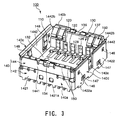
- FIG.3 is a perspective view illustrating a configuration of a connector according to an embodiment of the present invention.
- Connector 100 shown in FIG.3 according to the present embodiment is used when a camera module, which is an electronic component, is mounted on a substrate.
- this camera module mounted on the substrate through connector 100 has, for example, base part 220 (see FIG.7 ) that has virtually a rectangular parallelepiped shape in lower part 210 (see FIG.7 ) of a lens unit with a lens that guides light to a solid state imaging sensor such as a CMOS camera module, and that has contacts on a rectangular-shaped bottom face along two separate parallel sides.
- Connector 100 holds the camera module by accommodating this base part 220.
- Connector 100 shown in FIG.3 has housing 130 that opens upwards, that is formed as a square box with concave container 110 for accommodating a camera module (not shown) and that has contact pins 120, shell part 140 that is rectangular from a plane view and that covers the periphery of housing 130, and retaining members 150 that lock the camera module accommodated in container 110 to prevent the camera module from falling.
- the connector body is formed with housing 130 and shell part 140.
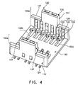
- FIG. 4 is a perspective view of the housing removing the shell part in the connector according to an embodiment of the present invention.
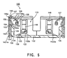
- FIG.5 is a cross sectional view illustrating the configuration of the connector shown in FIG.3 .
- Housing 130 shown in FIG.3 to FIG.5 is formed with insulating substances such as plastic, and has flat rectangular bottom plate part 132 and side wall parts 134 and 135 that rise vertically from two separate parallel sides in bottom plate part 132.
- Bottom plate part 132 defines the bottom face part of container 110 and matches with the shape of the bottom face (the bottom face of the base part) of the camera module to be accommodated in container 110. Further, side wall parts 134 and 135 are placed facing each other and define a pair of side wall parts of container 110 with facing inner peripheral surfaces.
- bottom plate part 132 along two sides of bottom plate part 132, a plurality of slits 132a are formed extending in directions facing each other, and contact parts 122 which form the tip parts of contact pins 120 are arranged in parallel projecting upward from these slits 132a on bottom plate part 132.
- Contact pins 120 are connected with the contacts of the camera module to be accommodated in container 110, and are provided in side wall parts 134 and 135 such that these contact pins 120 are pressed into places meeting contacts provided on the bottom face of the camera module (the bottom face of the base part).
- These contact pins 120 are each formed with flexible conducting members and formed by processing (e.g. bending) a long metal plate.
- contact pins 120 have lead part 124 that are each formed with a long conductive metal plate and that stick out from the lower end of housing 120 in parallel to the bottom face of connector 100 (the lower face of housing 130), pin fixing part 126 provided in the side wall and pin arm part 128 that forms contact part 122 at the tip.
- Lead part 124 is joined with the pattern on the substrate when connector 100 is placed on the substrate and continues with one end of pin fixing part 126 that forms the center of contact pin 120 at the base end.
- Pin fixing parts 126 are reverse U-shaped so that pin fixing parts 126 rise upward from the base end of lead parts 124 in wall parts 134 and 135 and fall downward from the upper ends of these rising parts.
- FIG. 3 and FIG. 4 show only the falling parts which appear in the side of container 110 and, FIG.5 shows rising parts.
- Pin arm parts 128 are bent from the tips of the falling parts and are inserted in slits 132a of bottom plate part 132 from the lower ends of side wall parts 134 and 135. By this means, pin arm parts 128 project at an upward angle, toward the interior of the container from the lower ends of side wall parts 134 and 135 and are elastically deformable in the downward direction (the direction of insertion with respect to the container of the camera module).
- contact parts 122 which form the tips of pin arm parts 128, are placed in container 110 and are positioned movably in the direction of insertion of the camera module.
- Contact parts 122 are urged in the direction opposite to the direction of insertion (for example, the removing direction).
- the direction of insertion of the camera module and the direction of press of the camera module are the same direction. For this reason, by inserting the camera module in the container, contact parts 122 touch contacts of the camera module such that contact parts 122 and the contact press against each other.
- Contact pins 120 are provided in side wall parts 134 and 135 at regular intervals in the horizontal direction which crosses the direction of insertion at right angles. Further, contact parts 122 of contact pins 120 in side wall parts 134 and 135 are positioned facing each other sandwiching bottom plate part 132.
- FIG.4 shows the lower parts of both side wall parts 134 and 135, and notch parts 137.
- FIG. 6 is a plan view illustrating the configuration of the connector according to an embodiment of the present invention.
- shell part 140 surrounding the periphery of housing 130 covers the back faces and both end parts of a pair of facing side wall parts 134 and 135.
- shell part 140 has a pair of back plate parts 140a and 140b that are parallel to each other and that are positioned on the back faces of side wall parts 134 and 135 rising upward from two sides of base plate part 132, and a pair of side plate parts 140c and 140d that connect with both ends of a pair of back plate parts 140a and 140b at right angles and that cover a pair of side wall parts 134 and 135 from the side.
- Container 110 of connector 100 is defined by a pair of side wall parts 134 and 135 and a pair of side plate parts 140c and 140d.
- pressing plates 148 are formed that project toward container 110 from the upper end and that are elastically deformable toward the interior.
- pressing plates 148 press against the sides of the camera module inserted in container 110 and hold the camera module.
- retaining members 150 attached to back plate parts 140a and 140b are positioned in a state where retaining members 150 project tip parts toward container 110 inserting in notch parts 137 of side wall parts 134 and 135.
- shell part 140 with back plate parts 140a and 140b in which retaining members 150 are provided, will be described in detail.
- shell part 140 has frame body part 142 that is rectangular cylindrical-shaped and that is fit onto the lower part of housing 130 and, above frame bodypart 142, auxiliary frame part 144 that is rectangular cylindrical-shaped and that is made to match and fit the outer shape of frame body part 142.
- Frame body part 142 has lower frames 1421 that are positioned along the lower back of a pair of side wall parts 134 and 135 and form the lower parts of back plate parts 140a and 140b, and outer plate frames 1422 that cross both ends of lower frames 1421 at right angles and that configure outer face parts of side plate parts 140c and 140d.
- ground terminal parts 1421a and 1422a which are connected with the ground part of the substrate when the lower parts are mounted on the substrate, are formed (see FIG.3 and FIG.5 ).
- outer plate frame 1422 of frame body part 142 (the length in the direction of insertion with respect to the container of the camera module) is nearly equal to the height of side wall parts 134 and 135.
- inner plate frame 1442 of auxiliary frame 144 is provided between outer plate frame 1422 and the side part of bottom plate part 132 along the direction of extension of outer plate frame 1422.
- This inner plate frame 1442 configures the interior parts of side parts 140c and 140d and forms side plate parts 140c and 140d of shell part 140 with outer plate frame 1422. Further, in the upper end side of inner plate frame 1442, frange part 1442b is formed inclining outward along the upper end side, and this frange part 1442b guides the module smoothly into container 110.
- retaining members 150 are provided with tip parts (claw parts 150 shown in FIG.5 and FIG.7 ) that extend upward and bend back near the upper end parts of side wall parts 134 and 135, so that the tip parts project toward container 110.
- upper frames 1441 of auxiliary frames 144 are provided above lower frames 1421 of frame body parts 142 in the back of retaining members 150, and upper frames 1441 configure the upper parts of back plate parts 140a and 140b.
- each retaining member 150 is formed integrally by the same metal plate as lower frames 1421 and is flexible.
- the part of this retaining member 150 projecting toward container 110 is positioned to incline at a downward angle from the upper parts of side wall parts 134 and 135 of housing 130 toward container 110, and is elastically deformed in the direction where a module approaches. This allows the lower side parts (claw parts 150 shown in FIG. 5 and FIG.7 ) to move toward side wall parts 134 and 135.
- Retaining member 150 is formed by carrying out the bending process on the long, flat flexible member that configures shield part 140.
- retaining member 150 is formed by carrying out the bending process on a long flat metal plate, which is elastically deformable, at separate predetermined positions in the longitudinal direction.
- Retaining member 150 shown in FIG. 3 , FIG. 5 and FIG. 6 is formed by bending part of the thin metal plate that forms shield part 140, that is, the part of the metal part that continues with lower frame 1421. That is, retaining member 150 is formed integrally with shield part 140, which is rectangular cylindrical-shaped, so that it is possible to reduce labor upon assembling compared to the connector configured apart from shield part 140.
- retaining member 150 has first body part 154 that bends along the bottom face of notch part 137, from the tip of lower frame 1421 rising from the base end part along the outer face of housing 130, and that projects toward the interior of container 110, second body part 156 that bends from the tip of first body part 154 toward the outside of container 110 and that inclines at an upward angle, arm part 158 that bends from the tip of second body part 156 toward the interior of container 110 and that extends inclining at a downward angle and claw part 159 formed at the tip of the arm part.
- First body part 154 is provided to bend from the upper end of lower frame 1421 projecting toward the interior (i.e. toward container part 110) of lower frame 1421.
- Tip part 154a of first body part 154 is positioned approximately the middle of the thickness of side wall part 134 (side wall part 135) covered by lower frame 1421 in notch part 137, and is configured such that second body part 156 extends upward from this tip part 154a.
- Upper end part 156a of second body part 156 is placed closer to the interior, that is, closer toward container part 110, than is positioned on virtually the same plane as the plane on which lower frame 1421 is positioned, and is positioned at virtually the same height of the upper end part of side wall part 134 (side wall part 135).
- upper end part 156a of second body part 156 is positioned above lower frame 1421, closer to the interior than upper frame 1441 positioned in virtually the same plane as lower frame 1421, and the back part of upper end part 156a opposes the interior of upper frame 1441.
- part of the back part of second body part 156 that is, the back part of upper endpart 156a, is positioned to abut on upper frame 1441. That is, upper frame 1441 functions as a limiting wall part that limits the movement of second body part 156 in the direction going away from container 110.
- Arm part 158 which continues to upper end part 156a of this second body part 156 projects toward container 110, and, at the tip part of arm part 158, claw part 159 that curves the lower face and that engages with engaged part 230 of the camera module (see FIG.8 ) is formed.
- arm part 158 projects tip part 158a to approximately the center part of arm part 158, toward the interior from the inner wall of side wall part 134 (side wall part 135).
- lower frame 1421 and first body part 154, first body part 154 and second body part 156, and second body part 156 and arm part 158 continue with each other through the curved, bending parts.
- angles between lower frame 1421 and first body part 154, first body part 154 and second body part 156, and second body part 156 and arm part 158 decrease in order from between lower frame 1421 and first body part 154, first body part 154 and second body part 156, and second body part 156 and arm part 158.
- first body part 154, second body part 156 and arm part 158 are positioned movably inside notch part 137.
- first bending part 153 and arm part 158 configures the elastically deforming part for moving the tip of claw part 159 out of container 110, so that it is possible to reliably secure elasticity even if retaining member 150 is formed with a thin, flat shape and enable an easy process and lower cost.
- pressing plates 148 formed in side wall parts 140c and 140d are formed with a flexible member, are formed integrally with inner plate frames 1442 and are positioned to project toward container 110 from the interior of inner plate frame 1442.
- each pressing plate 148 is formed to extend from the upper end toward the lower end and the center part that projects toward container 110 by elastic deformation, is movable toward the interior of inner plate frame 1442.
- FIG.7 is a cross sectional view of essential parts showing a state where a camera module is attached to the connector according to the present invention.
- camera module 200 shown in FIG.7 differs from the conventional camera module only in the height from the bottom face to the upper face, and the basic configuration of parts to be accommodated in connector 100 are virtually the same. That is, in camera module 200, on the upper part of the outer rim part of base part 220 that extends outward, engaged part 230 that engages with retaining member 150 of connector 100 when camera module 200 is attached to connector 100, is formed.
- retaining members 150 When a camera module is inserted in container 110 of connector 100, retaining members 150 are pressed against the inner peripheral faces of side wall parts 134 and 135 of housing 130 by the side faces of base part 220 of camera module 200, and are deformed.
- retaining members 150 When retaining members 150 is positioned in the sides of the engaging spaces, the urge applied to retaining members 150 is released, and retaining members 150 project toward the interior of container 110, engage with engaged parts 230 of the camera module and limits the movement in the removing direction of camera module 200 (the opposite direction to the direction of insertion). By this means, it is possible to prevent camera module 200 falling from the connector.
- camera module 200 is urged in the removing direction by contact parts 122 of contact pins 120 projecting upward from bottom face 132b of connector 100, that is, in removing direction M1, and is pressed down from above by claw parts 159 of retaining members 150 engaging with engaged parts 230.
- Movement of camera module 200 in removing direction M1 applies weight to arms 158 of retaining members 150 in direction M2 going away from camera module 200. Due to the weight applied to these arms 158 in direction M2, second body part 156 moves toward upper frame 1441 using bending part 155 as a starting point.
- claw parts 159 of retaining members 150 are limited involuntarily from moving in the direction of releasing the engagement with engaged parts 230 of camera module 200, and the engaged state of claw parts 159 with engaged parts 230 is held.
- retaining members 150 is opposite to the back faces of upper frames 1441 forming the upper parts of back plate parts 140a and 140b in upper end parts 156a of second body parts 156. For this reason, when camera module 200 moves from connector 100 in the removing direction, following the movement of claw parts 159 toward notch parts 137, second body parts 156 move toward upper frames 1441 using bending parts 155 as a starting point.
- upper end part 156a of second body part 156 abuts on the back face of upper frame 1441, which limits the movement of upper end part 156a, and limits the movement of claw part 159 continuing to second body part 156 through arm part 158 toward notch part 137.
- connector 100 has: a connector body that has housing 130 with container 110 to which module 200 is inserted and which opens upward, and shell part 140; contact pins (connecting parts) 120 that are provided inside container 110 and that electrically connect with the module to be accommodated in container 110; and flexible retaining members 150 that are provided in sides of container 110 in the connector body, that are deformed elastically when module 200 is inserted such that tip parts 159 of armparts 158, whichprojects toward container 119, move toward container 110 and that are restored to the original state when module 200 is accommodated in container 110 so that tip parts 159 engage with the front face (engaging part 230) of module 200.
- Arm parts 158 are provided to bend toward container 110 from the top end part of the body part provided along the direction of insertion on the side of container 110.
- the body part has first body part 154 that projects toward container 110 on the side of the container and second body part 156 that bends from the tip of first body part 154 in the direction going away from container 110 and extends upward.
- connector 100 of the present embodiment is able to reliably prevent camera module 200 to be accommodated in container 110 from falling from connector 100 and make connectors in lower profile by lowering the height of the side wall parts surrounding container 110.
- upper frame 1441 is configured to abut only on the back face of second body part 156 in retaining member 150
- the present invention is not limited to this, and a configuration may be possible where, in connector 100 with the above configuration, upper side part 1445 that projects toward container 110 from the upper end part of upper frame 1441 as shown in FIG.8 and that covers the upper ends of side wall parts 134 and 135 may be possible.
- upper frame 1441 and upper end side part 1445 are positioned on the upper face and the outer face of second body part 156 having the inner face facing container 110.
- side plate parts 140c and 140d of shell part 140 surrounding housing 130 are configured by superimposing auxiliary plate frame 1422 of frame body part 142 and inner plate frame 1442 of auxiliary frame 144.
- shell part 140 is positioned to surround a pair of side wall parts 134 and 135 and has a pair of flat side plate part 140c and 140d that bridge between side parts which are spaced apart facing each other in a pair of side wall parts 134 and 135.
- These side plate parts 140c and 140d form container 110 together with bottom plate part 132 and a pair of side wall parts 134 and 135.
- a pair of side walls facing each other are formed only with outer plate frame 1422 and inner plate frame 1442 of shell part 140 formed with the metal plate, instead of using side wall parts of housing 130 made of a resin having a thickness.
- the thickness of a pair of side wall parts facing each other is thinner than side wall parts including side wall parts 134 and 135 of housing 130, and the pair of side wall parts are formed by outer plate frame 1442 and inner plate frame 1422 formed by a stronger metal than resin side wall parts.
- connector 100 compared to conventional connectors that surround container 110 by surrounding walls, in connector 100 according to the present embodiment, the distance between the side wall parts is made shorter by the thickness of the length A of the side wall parts. Consequently, it is possible to make a smaller space for mounting a connector on the substrate than with conventional connectors.
- side plate parts 140c and 140d of shell part 140 formed with outer plate frames 1422 and inner plate frames 1442 have lock check window parts 146 that penetrate thorough the front and back faces of parts corresponding to the positions where the camera module inserted in container 110 engages with retaining members 150.
- lock check window parts 146 enable operators to check the connector from outside by seeing the engaging state of retaining members 150 with respect to the camera module accommodated in container 110.
- side plate parts 140c and 140d of shell part 140 formed with outer plate frames 1422 and inner plate frames 1442 have contact check window parts 147 that penetrate the front and back faces of parts corresponding to the height of the point of contact where contacts of the camera module inserted in container 110 touch contact pins 120.
- These contact check window parts 147 enable operators to check the connector from outside by seeing the contact state of contact pins 120 of connector 100 with contacts of the camera module accommodated in the container.
- contact pins 120 provided in housing 130 are positioned such that contact parts 122 extend upward from the bottom face of container 110
- the present invention is not limited to this, and a configuration may be possible where, in housing 130, pin arm parts 128 project toward container 110 from the inner peripheral faces of side wall parts 134 and 135 of housing 130 and touch contacts of the camera module in the side of the camera module accommodated in container 110.
- notch parts 137 formed in housing 130 are formed on both sides of upper side parts134a and 135a in a pair of side wall parts 134 and 135, the present invention is not limited to this, and any number of notch parts may be formed in any positions of parts of surrounding walls surrounding container 110.
- any shape and any number of retaining members 150 arranged inside these notch parts 137 may be possible.
- the side wall parts surrounding container 110 have pressing plates 148 and retaining members 150 projecting from the inner peripheral faces toward container 110.
- pressing plates 148 and retaining members 150 are provided such that container 110 is surrounded as the center and press against camera module 200 (see FIG.8 ) accommodated in container 110, toward the camera module.
- retaining members 150 and pressing plates 148 are able to place camera module 200 in the center in container 110 and suitably insert camera module 200 in container 110.
- retaining member 150 is formed by carrying out the bending process on the long, flat flexible member forming shell part 140.
- Retaining member 150 is formed by carrying out the bending process on the long, flat metal plate that is elastically deformable at separate predetermined positions in the longitudinal direction.
- retaining member 150 is formed by bending part of the thin, flat metal plate forming shell part 140, that is, by bending a part of the metal plate continuing to lower frame 1421. That is, retaining member 150 is formed integrally with shell part 140 which is rectangular-shaped, so that it is possible to reduce labor upon assembling compared to the connector which is configured apart from shell part 140.
- side plate part 140d of side plate parts 140c and 140d have keyway 140e opening upward.
- a convex part matching with this keyway 140e is provided with camera module 200 (see FIG.8 ).
- shell part 140 is box shaped and the metal plate is processed such that shell part 140 is formed integrally with retaining members 150. For this reason, when the connector with housing 130 and shell part 140 is assembled, it is possible to reduce labor upon assembling compared to cases where retaining members 150 are separate bodies.
- retaining members 150 prevent camera module 200 from falling
- the present invention is not limited to this, and the number of retaining members 150 may be one, two, three, four or more.
- the above present invention can be variously modified without departing from the spirit of the present invention, and it naturally follows that the present invention includes such modifications.
- the connector according to the present invention is useful when modules such as camera modules are mounted detachably in electronic devices such as mobile phones.
Landscapes
- Studio Devices (AREA)
- Details Of Connecting Devices For Male And Female Coupling (AREA)
- Connecting Device With Holders (AREA)
- Camera Bodies And Camera Details Or Accessories (AREA)
- Connector Housings Or Holding Contact Members (AREA)
- Coupling Device And Connection With Printed Circuit (AREA)
Abstract
Description
- The present invention relates to a module connector to which a module such as a camera module with a solid state image sensor is connected.
- Conventionally, as disclosed in, for example, Japanese Patent Application Laid-Open No.
2006-67443 -
FIG.1 and FIG. 2 illustrate a conventional connector.FIG.1 is a schematic longitudinal cross-sectional view showing a connector, illustrating the configuration of the conventional connector and a module mounted in the connector.FIG.2 is a schematic cross-sectional view showing a state where the module is attached to the connector shown inFIG.1 . -
Connector 10 shown inFIG.1 and FIG.2 attaches built-inmodule 20 to the equipment. - First,
module 20 attached to thisconnector 10 will be described.Module 20 is a camera module mounted in, for example, mobile telephones, and haslens part 24 abovemodule body 23 which is approximately a quadrilateral and hassubstrate 21 in the bottom face. Further, near corner parts inmodule body 23,engaging parts 22 are formed by making a notch that continues from the middle to the upper face ofmodule body 23. Further,substrate 21 has a plurality of contact pads (not shown) connected with the contact segments ofconnector 10. -
Connector 10 hashousing 12 that opens upward and that hascontainer 11 which builds inmodule 20, contact segments (not shown) that electrically connect with contact pads ofsubstrate 21 insidecontainer 11 andspring hooks 13 that engage withengaging parts 22 ofmodule 20. -
Spring hooks 13 are flexible and extend towardcontainer 11 fromshield cases 14 covering the outer peripheral surfaces ofhousing 12, engage withengaging parts 22 of the module to be accommodated incontainer 11 at the tips offree tip parts 13a and thereby prevent the module from falling. -
Spring hooks 13 are each placed to incline from the top end part ofshield case 14 toward the center ofbottom face 10a ofcontainer 11 through insidehousing 12, andfree tip parts 13a are each positioned inside the container. - By
building module 20 incontainer 11 by pressing downmodule 20 fromabove connector 10 intocontainer 11,spring hooks 13 are elastically deformed by the downward press by the bottom face ofmodule 20 and escape outward. - Then, when
module 20 is inserted to a predetermined position insidecontainer 11,free tip parts 13a ofspring hooks 13 are restored to the original state, maintaining the contact pads of the substrate in contact with the contact segments and engage withengaging faces 22a ofengaging parts 22, that is, the upper face of module 20 (seeFIG.2 ). By this means,spring hooks 13 preventmodule 20 attached toconnector 10 from falling. - Further, when the camera module is removed,
free tip parts 13a ofspring hooks 13 slide pressing against the side faces of the camera module moving in the removing direction off the lock positions withengaging parts 22. - To prevent deformation of
spring hooks 13 itself due to this slide and secure the restoring force offree tip parts 13a,spring hooks 13 are configured to have deforming parts of a predetermined length L from the top end ofshield cases 14 tofree tip parts 13a. - Recently, electronic devices such as mobile telephones in which modules such as camera modules are mounted, are miniaturized, and, accompanying this, making module connectors itself in lower profile used in mounting in the module is desired.
- However, according to the configuration of a conventional module connector, to prevent deformation of
spring hooks 13 when the module is removed and secure the restoring force offree tip parts 13a, the length L of deforming parts between the top ends ofshield cases 14 andfree tip part 13a need to be secured. - For this reason, the side wall
parts surrounding container 11 require a height L2 so that the length L of the deforming parts extending from the top end of the side wall parts towardbottom face 10a ofcontainer 11 is secured, and it was difficult to make module connectors in lower profile. - It is therefore an object of the present invention to provide a module connector that is able to reliably lock modules such as camera modules, which are accommodated, to prevent the modules from falling and make module connectors in lower profile.
- The present invention has a connector body with a container in which a module is inserted and which opens upward; a connecting part which is provided inside the container and which electrically connects with the module accommodated in the container; and a flexible retaining member which is provided in a side of the container in the connector body, which deforms elastically when the module is inserted such that a tip part of an arm part projecting toward the container moves to the side of the container and which restores to an original state when the module is accommodated in the container so that the tip part engages with a front face of the module, whereby: the arm part is provided to bend toward the container from an upper end part of a body part provided in the side of the container along the direction of insertion; and the body part comprises a first body part that projects toward the container in the side of the container and a second body part that bends from a tip of the first body part in a direction going away from the container and extends upward, and achieves the above object.
-
-
FIG.1 illustrates a conventional connector; -
FIG.2 illustrates a conventional connector; -
FIG.3 is a perspective view illustrating a configuration of a module connector according to an embodiment of the present invention; -
FIG.4 is a perspective view of a housing that removes a shell part from the connector; -
FIG.5 is a cross sectional view illustrating the configuration of the module connector shown inFIG.3 ; -
FIG. 6 is a plan view illustrating the configuration of the module connector according to an embodiment of the present invention; -
FIG.7 is a cross sectional view of essential parts showing a state where a camera module is attached to the module connector according to an embodiment of the present invention; and -
FIG.8 illustrates an example of a variation of the module connector according to an embodiment of the present invention. - An embodiment of the present invention will be described below in detail with reference to the accompanying drawings.
-
FIG.3 is a perspective view illustrating a configuration of a connector according to an embodiment of the present invention.Connector 100 shown inFIG.3 according to the present embodiment is used when a camera module, which is an electronic component, is mounted on a substrate. - Further, this camera module mounted on the substrate through
connector 100 has, for example, base part 220 (seeFIG.7 ) that has virtually a rectangular parallelepiped shape in lower part 210 (seeFIG.7 ) of a lens unit with a lens that guides light to a solid state imaging sensor such as a CMOS camera module, and that has contacts on a rectangular-shaped bottom face along two separate parallel sides.Connector 100 holds the camera module by accommodating thisbase part 220. -
Connector 100 shown inFIG.3 hashousing 130 that opens upwards, that is formed as a square box withconcave container 110 for accommodating a camera module (not shown) and that hascontact pins 120,shell part 140 that is rectangular from a plane view and that covers the periphery ofhousing 130, and retainingmembers 150 that lock the camera module accommodated incontainer 110 to prevent the camera module from falling. Inconnector 100, the connector body is formed withhousing 130 andshell part 140. -
FIG. 4 is a perspective view of the housing removing the shell part in the connector according to an embodiment of the present invention.FIG.5 is a cross sectional view illustrating the configuration of the connector shown inFIG.3 . -
Housing 130 shown inFIG.3 to FIG.5 is formed with insulating substances such as plastic, and has flat rectangularbottom plate part 132 andside wall parts bottom plate part 132. -
Bottom plate part 132 defines the bottom face part ofcontainer 110 and matches with the shape of the bottom face (the bottom face of the base part) of the camera module to be accommodated incontainer 110. Further,side wall parts container 110 with facing inner peripheral surfaces. - As shown in
FIG. 3 andFIG. 4 , along two sides ofbottom plate part 132, a plurality ofslits 132a are formed extending in directions facing each other, andcontact parts 122 which form the tip parts ofcontact pins 120 are arranged in parallel projecting upward from theseslits 132a onbottom plate part 132. -
Contact pins 120 are connected with the contacts of the camera module to be accommodated incontainer 110, and are provided inside wall parts contact pins 120 are pressed into places meeting contacts provided on the bottom face of the camera module (the bottom face of the base part). - These
contact pins 120 are each formed with flexible conducting members and formed by processing (e.g. bending) a long metal plate. - To be more specific,
contact pins 120 havelead part 124 that are each formed with a long conductive metal plate and that stick out from the lower end ofhousing 120 in parallel to the bottom face of connector 100 (the lower face of housing 130),pin fixing part 126 provided in the side wall andpin arm part 128 that formscontact part 122 at the tip. -
Lead part 124 is joined with the pattern on the substrate whenconnector 100 is placed on the substrate and continues with one end ofpin fixing part 126 that forms the center ofcontact pin 120 at the base end. -
Pin fixing parts 126 are reverse U-shaped so thatpin fixing parts 126 rise upward from the base end oflead parts 124 inwall parts FIG. 3 andFIG. 4 show only the falling parts which appear in the side ofcontainer 110 and,FIG.5 shows rising parts. - These falling parts are elastically deformable and are placed along the interiors of
side wall parts pin arm parts 128 located near the corners defined byside wall parts bottom plate part 132 continue with the tips. -
Pin arm parts 128 are bent from the tips of the falling parts and are inserted inslits 132a ofbottom plate part 132 from the lower ends ofside wall parts pin arm parts 128 project at an upward angle, toward the interior of the container from the lower ends ofside wall parts - By this means,
contact parts 122, which form the tips ofpin arm parts 128, are placed incontainer 110 and are positioned movably in the direction of insertion of the camera module. - Contact
parts 122 are urged in the direction opposite to the direction of insertion (for example, the removing direction). The direction of insertion of the camera module and the direction of press of the camera module are the same direction. For this reason, by inserting the camera module in the container,contact parts 122 touch contacts of the camera module such thatcontact parts 122 and the contact press against each other. - Contact
pins 120 are provided inside wall parts contact parts 122 ofcontact pins 120 inside wall parts bottom plate part 132. - As shown in
FIG.4 , at both ends ofupper end parts side wall parts contact pins 120 are provided,notch parts 137 are formed such thatnotch parts 137 keep lower levels than the center parts ofupper endparts FIG.5 shows the lower parts of bothside wall parts parts 137. -
FIG. 6 is a plan view illustrating the configuration of the connector according to an embodiment of the present invention. - As shown in
FIG.3 ,FIG.5 andFIG.6 ,shell part 140 surrounding the periphery ofhousing 130, covers the back faces and both end parts of a pair of facingside wall parts - As shown in
FIG.3 andFIG.6 ,shell part 140 has a pair ofback plate parts side wall parts base plate part 132, and a pair ofside plate parts back plate parts side wall parts -
Container 110 ofconnector 100 is defined by a pair ofside wall parts side plate parts - Further, as shown in
FIG. 3 andFIG. 6 , in the interiors ofside plate parts bottom plate part 132 and,pressing plates 148 are formed that project towardcontainer 110 from the upper end and that are elastically deformable toward the interior. When a camera module is inserted incontainer 110,pressing plates 148 press against the sides of the camera module inserted incontainer 110 and hold the camera module. - Further, in a pair of side wall parts formed by
side wall parts plate parts side wall parts bottom plate part 132, retainingmembers 150 attached to backplate parts members 150 project tip parts towardcontainer 110 inserting innotch parts 137 ofside wall parts - Here, the configuration of
shell part 140 withback plate parts members 150 are provided, will be described in detail. - As shown in
FIG.3 ,shell part 140 hasframe body part 142 that is rectangular cylindrical-shaped and that is fit onto the lower part ofhousing 130 and, aboveframe bodypart 142,auxiliary frame part 144 that is rectangular cylindrical-shaped and that is made to match and fit the outer shape offrame body part 142. -
Frame body part 142 haslower frames 1421 that are positioned along the lower back of a pair ofside wall parts back plate parts lower frames 1421 at right angles and that configure outer face parts ofside plate parts - In the lower side parts of frame body part 142 (to be more specific, the lower side part of
lower frame 1421 and the lower side part of outer plate frame 1422),ground terminal parts FIG.3 andFIG.5 ). - The height of
outer plate frame 1422 of frame body part 142 (the length in the direction of insertion with respect to the container of the camera module) is nearly equal to the height ofside wall parts - Further,
inner plate frame 1442 ofauxiliary frame 144 is provided betweenouter plate frame 1422 and the side part ofbottom plate part 132 along the direction of extension ofouter plate frame 1422. - This
inner plate frame 1442 configures the interior parts ofside parts side plate parts shell part 140 withouter plate frame 1422. Further, in the upper end side ofinner plate frame 1442,frange part 1442b is formed inclining outward along the upper end side, and thisfrange part 1442b guides the module smoothly intocontainer 110. - At both ends of the upper side part of
lower frame 1421, retainingmembers 150 are provided with tip parts (clawparts 150 shown inFIG.5 andFIG.7 ) that extend upward and bend back near the upper end parts ofside wall parts container 110. - Further,
upper frames 1441 ofauxiliary frames 144 are provided abovelower frames 1421 offrame body parts 142 in the back of retainingmembers 150, andupper frames 1441 configure the upper parts ofback plate parts - Here, each retaining
member 150 is formed integrally by the same metal plate aslower frames 1421 and is flexible. - The part of this retaining
member 150 projecting towardcontainer 110 is positioned to incline at a downward angle from the upper parts ofside wall parts housing 130 towardcontainer 110, and is elastically deformed in the direction where a module approaches. This allows the lower side parts (clawparts 150 shown inFIG. 5 andFIG.7 ) to move towardside wall parts - Retaining
member 150 is formed by carrying out the bending process on the long, flat flexible member that configuresshield part 140. Here, retainingmember 150 is formed by carrying out the bending process on a long flat metal plate, which is elastically deformable, at separate predetermined positions in the longitudinal direction. - Retaining
member 150 shown inFIG. 3 ,FIG. 5 andFIG. 6 is formed by bending part of the thin metal plate that formsshield part 140, that is, the part of the metal part that continues withlower frame 1421. That is, retainingmember 150 is formed integrally withshield part 140, which is rectangular cylindrical-shaped, so that it is possible to reduce labor upon assembling compared to the connector configured apart fromshield part 140. - To be more specific, as shown in
FIG.5 , retainingmember 150 hasfirst body part 154 that bends along the bottom face ofnotch part 137, from the tip oflower frame 1421 rising from the base end part along the outer face ofhousing 130, and that projects toward the interior ofcontainer 110,second body part 156 that bends from the tip offirst body part 154 toward the outside ofcontainer 110 and that inclines at an upward angle,arm part 158 that bends from the tip ofsecond body part 156 toward the interior ofcontainer 110 and that extends inclining at a downward angle and clawpart 159 formed at the tip of the arm part. -
First body part 154 is provided to bend from the upper end oflower frame 1421 projecting toward the interior (i.e. toward container part 110) oflower frame 1421. -
Tip part 154a offirst body part 154 is positioned approximately the middle of the thickness of side wall part 134 (side wall part 135) covered bylower frame 1421 innotch part 137, and is configured such thatsecond body part 156 extends upward from thistip part 154a. -
Upper end part 156a ofsecond body part 156 is placed closer to the interior, that is, closer towardcontainer part 110, than is positioned on virtually the same plane as the plane on whichlower frame 1421 is positioned, and is positioned at virtually the same height of the upper end part of side wall part 134 (side wall part 135). Here,upper end part 156a ofsecond body part 156 is positioned abovelower frame 1421, closer to the interior thanupper frame 1441 positioned in virtually the same plane aslower frame 1421, and the back part ofupper end part 156a opposes the interior ofupper frame 1441. Further, part of the back part ofsecond body part 156, that is, the back part of upper endpart 156a, is positioned to abut onupper frame 1441. That is,upper frame 1441 functions as a limiting wall part that limits the movement ofsecond body part 156 in the direction going away fromcontainer 110. -
Arm part 158 which continues toupper end part 156a of thissecond body part 156 projects towardcontainer 110, and, at the tip part ofarm part 158, clawpart 159 that curves the lower face and that engages withengaged part 230 of the camera module (seeFIG.8 ) is formed. - Further,
arm part 158 projects tippart 158a to approximately the center part ofarm part 158, toward the interior from the inner wall of side wall part 134 (side wall part 135). - In retaining
member 150 of the present embodiment,lower frame 1421 andfirst body part 154,first body part 154 andsecond body part 156, andsecond body part 156 andarm part 158 continue with each other through the curved, bending parts. Here, angles betweenlower frame 1421 andfirst body part 154,first body part 154 andsecond body part 156, andsecond body part 156 andarm part 158 decrease in order from betweenlower frame 1421 andfirst body part 154,first body part 154 andsecond body part 156, andsecond body part 156 andarm part 158. - With this retaining
member 150, bendingpart 153 betweenlower frame 1421 andfirst body part 154,first body part 154, bendingpart 155 betweenfirst body part 154 andsecond body part 156, bendingpart 157 betweensecond body part 156 andarm part 158, andarm part 158 intervene between the upper end oflower frame 1421 and clawpart 159. - The base end parts of
first body part 154,second body part 156 andarm part 158 are positioned movably insidenotch part 137. - Even in a configuration where the height of
connector 100 is lowered and the level of the height of side wall parts definingcontainer part 110 in which retainingmember 150 are provided is limited to make connectors in lower profile, it is possible to secure the length of the elastically deforming part (i.e. the length from theupperendoflower frame 1421 toclawpart 159) required to move the tip ofclaw part 159 projecting towardcontainer 110, to the outside ofcontainer 110 without exceeding the level of the height of the side wall parts. - Further, with retaining
member 150, the configuration between first bendingpart 153 andarm part 158 configures the elastically deforming part for moving the tip ofclaw part 159 out ofcontainer 110, so that it is possible to reliably secure elasticity even if retainingmember 150 is formed with a thin, flat shape and enable an easy process and lower cost. - Further, in
shell part 140,pressing plates 148 formed inside wall parts container 110 from the interior ofinner plate frame 1442. Here, in the interior ofinner plate frame 1442, eachpressing plate 148 is formed to extend from the upper end toward the lower end and the center part that projects towardcontainer 110 by elastic deformation, is movable toward the interior ofinner plate frame 1442. - Next, the operation of attaching the camera module to
connector 100 according to the present embodiment will be described. -
FIG.7 is a cross sectional view of essential parts showing a state where a camera module is attached to the connector according to the present invention. Further,camera module 200 shown inFIG.7 differs from the conventional camera module only in the height from the bottom face to the upper face, and the basic configuration of parts to be accommodated inconnector 100 are virtually the same. That is, incamera module 200, on the upper part of the outer rim part ofbase part 220 that extends outward, engagedpart 230 that engages with retainingmember 150 ofconnector 100 whencamera module 200 is attached toconnector 100, is formed. - When a camera module is inserted in
container 110 ofconnector 100, retainingmembers 150 are pressed against the inner peripheral faces ofside wall parts housing 130 by the side faces ofbase part 220 ofcamera module 200, and are deformed. - Then, contacts (not shown) of the bottom face of
base part 220 abut on and pressdownward contact parts 122. The contacts and contactparts 122 touch one another such that the contacts and contactparts 122 press against each other (not shown). Whencamera module 200 moves downward, retainingmembers 150 slide on the side faces ofbase part 220 ofcamera module 200 and move to the engaging spaces above engagedparts 230 formed incamera module 200. - When retaining
members 150 is positioned in the sides of the engaging spaces, the urge applied to retainingmembers 150 is released, and retainingmembers 150 project toward the interior ofcontainer 110, engage with engagedparts 230 of the camera module and limits the movement in the removing direction of camera module 200 (the opposite direction to the direction of insertion). By this means, it is possible to preventcamera module 200 falling from the connector. - At this time,
camera module 200 is urged in the removing direction bycontact parts 122 of contact pins 120 projecting upward frombottom face 132b ofconnector 100, that is, in removing direction M1, and is pressed down from above byclaw parts 159 of retainingmembers 150 engaging with engagedparts 230. - Movement of
camera module 200 in removing direction M1 applies weight toarms 158 of retainingmembers 150 in direction M2 going away fromcamera module 200. Due to the weight applied to thesearms 158 in direction M2,second body part 156 moves towardupper frame 1441 using bendingpart 155 as a starting point. -
Upper end parts 156a ofsecond body parts 156 which moved abut on the back faces ofupper frames 1441 configuring the upper parts ofback plate parts second body parts 156, that is, the movement in the direction of releasing the engaging state ofclaw parts 159. - Therefore, claw
parts 159 of retainingmembers 150 are limited involuntarily from moving in the direction of releasing the engagement with engagedparts 230 ofcamera module 200, and the engaged state ofclaw parts 159 with engagedparts 230 is held. - In this way, according to
connector 100 of the present embodiment, retainingmembers 150 is opposite to the back faces ofupper frames 1441 forming the upper parts ofback plate parts upper end parts 156a ofsecond body parts 156. For this reason, whencamera module 200 moves fromconnector 100 in the removing direction, following the movement ofclaw parts 159 towardnotch parts 137,second body parts 156 move towardupper frames 1441 using bendingparts 155 as a starting point. - By this means,
upper end part 156a ofsecond body part 156 abuts on the back face ofupper frame 1441, which limits the movement ofupper end part 156a, and limits the movement ofclaw part 159 continuing tosecond body part 156 througharm part 158 towardnotch part 137. - In this way,
connector 100 has: a connector body that hashousing 130 withcontainer 110 to whichmodule 200 is inserted and which opens upward, andshell part 140; contact pins (connecting parts) 120 that are provided insidecontainer 110 and that electrically connect with the module to be accommodated incontainer 110; andflexible retaining members 150 that are provided in sides ofcontainer 110 in the connector body, that are deformed elastically whenmodule 200 is inserted such thattip parts 159 ofarmparts 158, whichprojects toward container 119, move towardcontainer 110 and that are restored to the original state whenmodule 200 is accommodated incontainer 110 so thattip parts 159 engage with the front face (engaging part 230) ofmodule 200. -
Arm parts 158 are provided to bend towardcontainer 110 from the top end part of the body part provided along the direction of insertion on the side ofcontainer 110. The body part hasfirst body part 154 that projects towardcontainer 110 on the side of the container andsecond body part 156 that bends from the tip offirst body part 154 in the direction going away fromcontainer 110 and extends upward. - Therefore, the movement of
claw parts 159 of retainingmembers 150 in the direction of releasing engagement withengaged part 230 ofcamera module 200 is limited involuntarily byupper frame 1441, so that it is possible to reinforce the engaging state withengaged part 230. - In this way,
connector 100 of the present embodiment is able to reliably preventcamera module 200 to be accommodated incontainer 110 from falling fromconnector 100 and make connectors in lower profile by lowering the height of the side wallparts surrounding container 110. - Although
upper frame 1441 is configured to abut only on the back face ofsecond body part 156 in retainingmember 150, the present invention is not limited to this, and a configuration may be possible where, inconnector 100 with the above configuration,upper side part 1445 that projects towardcontainer 110 from the upper end part ofupper frame 1441 as shown inFIG.8 and that covers the upper ends ofside wall parts - In this way, the movement of
claw part 159 of retainingmember 150 toward the outside ofcontainer 110 and abovecontainer 110 is limited involuntarily byupper frame 1441. - That is, when the movement in the direction of removing
module 200 accommodated insidecontainer 110 applies weight to armpart 158 throughclaw part 159 in direction M2,upper end part 156a ofsecond body part 156 abuts on the back face ofupper frame 1441 andbase end part 158b ofarm part 158 abuts onupper side part 1445. - In this way, according to the example of the variation of
connector 100 shown inFIG.8 ,upper frame 1441 and upperend side part 1445 are positioned on the upper face and the outer face ofsecond body part 156 having the innerface facing container 110. - By this means, the movement of retaining
members 150 toward the side ofcontainer 110 and abovecontainer 110 which are the destinations is limited involuntarily byupper frame 1441 andupper side part 1445. - Consequently, the movement of
claw part 159, which continues withtip part 158a ofarm part 158, toward the side of the container and above the container, that is, the movement in the direction of releasing the lock with engaged part 220 (seeFIG.7 ) of the module, is limited involuntarily, so that it is possible to increase the lock strength of retainingmembers 150 itself with respect to the module inserted. - Further, with the present embodiment,
side plate parts shell part 140surrounding housing 130 are configured by superimposingauxiliary plate frame 1422 offrame body part 142 andinner plate frame 1442 ofauxiliary frame 144. - Further,
shell part 140 is positioned to surround a pair ofside wall parts side plate part side wall parts side plate parts container 110 together withbottom plate part 132 and a pair ofside wall parts - That is, in the four side wall
parts surrounding container 110, a pair of side walls facing each other are formed only withouter plate frame 1422 andinner plate frame 1442 ofshell part 140 formed with the metal plate, instead of using side wall parts ofhousing 130 made of a resin having a thickness. In other words, inconnector 100, in the side wallparts surrounding container 110, the thickness of a pair of side wall parts facing each other (side plate parts side wall parts housing 130, and the pair of side wall parts are formed byouter plate frame 1442 andinner plate frame 1422 formed by a stronger metal than resin side wall parts. - By this means, compared to conventional connectors that surround
container 110 by surrounding walls, inconnector 100 according to the present embodiment, the distance between the side wall parts is made shorter by the thickness of the length A of the side wall parts. Consequently, it is possible to make a smaller space for mounting a connector on the substrate than with conventional connectors. - Therefore, even if various electronic parts are mounted on a substrate following improvement in functions of communication mobile terminals such as mobile telephones with camera modules in recent years, it is possible to make a smaller space for mounting a connector on a substrate, which differs from a conventional connector that requires resin side wall parts of a housing for surrounding side wall parts that define the container.
- Further,
side plate parts shell part 140 formed with outer plate frames 1422 and inner plate frames 1442 have lockcheck window parts 146 that penetrate thorough the front and back faces of parts corresponding to the positions where the camera module inserted incontainer 110 engages with retainingmembers 150. These lock checkwindow parts 146 enable operators to check the connector from outside by seeing the engaging state of retainingmembers 150 with respect to the camera module accommodated incontainer 110. - Further,
side plate parts shell part 140 formed with outer plate frames 1422 and inner plate frames 1442 have contactcheck window parts 147 that penetrate the front and back faces of parts corresponding to the height of the point of contact where contacts of the camera module inserted incontainer 110 touch contact pins 120. These contact checkwindow parts 147 enable operators to check the connector from outside by seeing the contact state of contact pins 120 ofconnector 100 with contacts of the camera module accommodated in the container. - Further, although, with
connector 100 of the present embodiment, contact pins 120 provided inhousing 130 are positioned such thatcontact parts 122 extend upward from the bottom face ofcontainer 110, the present invention is not limited to this, and a configuration may be possible where, inhousing 130,pin arm parts 128 project towardcontainer 110 from the inner peripheral faces ofside wall parts housing 130 and touch contacts of the camera module in the side of the camera module accommodated incontainer 110. - Further, although
notch parts 137 formed inhousing 130 are formed on both sides of upper side parts134a and 135a in a pair ofside wall parts walls surrounding container 110. - Further, as long as the configuration prevents the camera module accommodated in
container 110 from falling, any shape and any number of retainingmembers 150 arranged inside thesenotch parts 137 may be possible. - Further, in
connector 100, the side wallparts surrounding container 110 havepressing plates 148 and retainingmembers 150 projecting from the inner peripheral faces towardcontainer 110. - Here, from a plane view as shown in
FIG. 6 , pressingplates 148 and retainingmembers 150 are provided such thatcontainer 110 is surrounded as the center and press against camera module 200 (seeFIG.8 ) accommodated incontainer 110, toward the camera module. - By this means, retaining
members 150 andpressing plates 148 are able to placecamera module 200 in the center incontainer 110 and suitably insertcamera module 200 incontainer 110. - Further, retaining
member 150 is formed by carrying out the bending process on the long, flat flexible member formingshell part 140. Retainingmember 150 is formed by carrying out the bending process on the long, flat metal plate that is elastically deformable at separate predetermined positions in the longitudinal direction. - Here, retaining
member 150 is formed by bending part of the thin, flat metal plate formingshell part 140, that is, by bending a part of the metal plate continuing tolower frame 1421. That is, retainingmember 150 is formed integrally withshell part 140 which is rectangular-shaped, so that it is possible to reduce labor upon assembling compared to the connector which is configured apart fromshell part 140. - Further, as shown in
FIG.3 , inconnector 100,side plate part 140d ofside plate parts keyway 140e opening upward. A convex part matching with thiskeyway 140e is provided with camera module 200 (seeFIG.8 ). When thiscamera module 200 is inserted incontainer 110, by inserting the camera module incontainer 110 positioning the convex part of the camera module abovekeyway 140e, it is possible to position the camera module smoothly insidecontainer 110 while fitting the convex part intokeyway 140e and guiding the convex part in the direction of insertion and specify the front, back, left and right directions of the cameramodule in the insertion. - Further, in
connector 100,shell part 140 is box shaped and the metal plate is processed such thatshell part 140 is formed integrally with retainingmembers 150. For this reason, when the connector withhousing 130 andshell part 140 is assembled, it is possible to reduce labor upon assembling compared to cases where retainingmembers 150 are separate bodies. - Further, although, with the connector of the present embodiment, eight retaining
members 150 preventcamera module 200 from falling, the present invention is not limited to this, and the number of retainingmembers 150 may be one, two, three, four or more. Further, the above present invention can be variously modified without departing from the spirit of the present invention, and it naturally follows that the present invention includes such modifications. - The connector according to the present invention is useful when modules such as camera modules are mounted detachably in electronic devices such as mobile phones.
Claims (3)
- A module connector comprising:a connector body with a container (110) in which a module (200) is inserted and which opens upward;a connecting part (120) which is provided inside the container and which electrically connects with the module accommodated in the container; anda flexible retaining member (150) which is provided in a side of the container in the connector body, which deforms elastically when the module is inserted such that a tip part (159) of an arm part (158) projecting toward the container moves to the side of the container and which restores to an original state when the module is accommodated in the container so that the tip part engages with a front face of the module, wherein:the arm part is provided to bend toward the container from an upper end part of a body part provided in the side of the container along the direction of insertion; andthe body part comprises a first body part (154) that projects toward the container in the side of the container and a second body part (156) that bends from a tip of the first body part in a direction going away from the container and extends upward.
- The module connector according to claim 1, wherein, in the connector body, a limiting wall part (144) is positioned that limits movement of the second body part in the direction going away from the container.
- The module connector according to claim 2, wherein the limiting wall part (1441,1445) is positioned on an upper face and an outer face of the second body part facing toward an interior of the container.
Applications Claiming Priority (1)
| Application Number | Priority Date | Filing Date | Title |
|---|---|---|---|
| JP2007159449A JP2008311149A (en) | 2007-06-15 | 2007-06-15 | Module connector |
Publications (2)
| Publication Number | Publication Date |
|---|---|
| EP2026414A1 true EP2026414A1 (en) | 2009-02-18 |
| EP2026414B1 EP2026414B1 (en) | 2010-06-02 |
Family
ID=40132759
Family Applications (1)
| Application Number | Title | Priority Date | Filing Date |
|---|---|---|---|
| EP08010911A Not-in-force EP2026414B1 (en) | 2007-06-15 | 2008-06-16 | Module connector |
Country Status (7)
| Country | Link |
|---|---|
| US (1) | US7632132B2 (en) |
| EP (1) | EP2026414B1 (en) |
| JP (1) | JP2008311149A (en) |
| CN (1) | CN101325302A (en) |
| AT (1) | ATE470253T1 (en) |
| DE (1) | DE602008001412D1 (en) |
| TW (1) | TW200849734A (en) |
Families Citing this family (19)
| Publication number | Priority date | Publication date | Assignee | Title |
|---|---|---|---|---|
| JP2008113066A (en) * | 2006-10-27 | 2008-05-15 | Sony Corp | Imaging device |
| JP4840710B2 (en) * | 2009-07-22 | 2011-12-21 | Smk株式会社 | Camera module socket |
| JP2011154977A (en) * | 2010-01-28 | 2011-08-11 | Kel Corp | Ic connector and cover member for ic connector |
| JP5041557B2 (en) * | 2010-03-30 | 2012-10-03 | 日本航空電子工業株式会社 | connector |
| CN102315535B (en) * | 2010-06-30 | 2014-03-12 | 上海莫仕连接器有限公司 | Electric connector |
| JP5110334B2 (en) * | 2010-10-05 | 2012-12-26 | 第一精工株式会社 | Connector device |
| EP2625006B1 (en) | 2010-10-08 | 2016-12-07 | Milwaukee Electric Tool Corporation | Battery retention system for a power tool |
| US20120126678A1 (en) * | 2010-11-22 | 2012-05-24 | Nokia Corporation | Apparatus for Retaining an Object |
| JP5263553B2 (en) * | 2010-12-15 | 2013-08-14 | Smk株式会社 | Shield connector |
| US9007783B2 (en) * | 2011-05-31 | 2015-04-14 | Sony Corporation | Memory device and receptacle for electronic devices |
| CN102904102B (en) * | 2011-07-25 | 2016-03-02 | 上海莫仕连接器有限公司 | Electric connector and heavy plate type electric connector module |
| TWI558033B (en) * | 2011-11-22 | 2016-11-11 | 鴻海精密工業股份有限公司 | Plug device |
| MX2014009362A (en) * | 2012-02-01 | 2014-09-12 | Keylex Corp | Electrode inspection device for spot welding. |
| JP6376966B2 (en) * | 2014-12-16 | 2018-08-22 | 日本航空電子工業株式会社 | connector |
| US10264675B2 (en) * | 2017-04-18 | 2019-04-16 | Te Connectivity Corporation | Dual connector system |
| US10290962B2 (en) * | 2017-04-20 | 2019-05-14 | Te Connectivity Corporation | Dual connector system |
| CN107634392B (en) * | 2017-09-14 | 2020-04-07 | 上海摩软通讯技术有限公司 | Fixing device, board-to-board connector assembly and mobile terminal comprising same |
| EP3780564B1 (en) * | 2018-06-07 | 2023-03-01 | Huawei Technologies Co., Ltd. | Positioning device, camera module, and mobile terminal |
| CN111752066B (en) * | 2019-03-28 | 2022-05-03 | 日本电产三协株式会社 | Optical unit with shake correction function |
Citations (5)
| Publication number | Priority date | Publication date | Assignee | Title |
|---|---|---|---|---|
| US20030218873A1 (en) * | 2002-05-27 | 2003-11-27 | Nokia Corporation | Structure for fastening a component |
| US20050215087A1 (en) * | 2004-03-25 | 2005-09-29 | Smk Corporation | Electronic part-mounting socket |
| JP2006067443A (en) | 2004-08-30 | 2006-03-09 | Mitsumi Electric Co Ltd | Module connector locking device and camera module device using the locking device |
| US20060105631A1 (en) * | 2004-11-18 | 2006-05-18 | Hon Hai Precision Ind.Co., Ltd. | Shielded electrical connector with improved insulative housing |
| WO2007041484A1 (en) | 2005-09-30 | 2007-04-12 | Molex Incorporated | Module socket |
Family Cites Families (3)
| Publication number | Priority date | Publication date | Assignee | Title |
|---|---|---|---|---|
| JP2004063425A (en) * | 2002-07-31 | 2004-02-26 | Mitsumi Electric Co Ltd | Module connector |
| US7077664B1 (en) * | 2005-03-08 | 2006-07-18 | Cheng Uei Precision Industry Co., Ltd. | Module connector |
| CN2909597Y (en) * | 2006-03-30 | 2007-06-06 | 富士康(昆山)电脑接插件有限公司 | electrical connector |
-
2007
- 2007-06-15 JP JP2007159449A patent/JP2008311149A/en active Pending
-
2008
- 2008-05-02 TW TW097116222A patent/TW200849734A/en unknown
- 2008-06-12 CN CNA2008101256236A patent/CN101325302A/en active Pending
- 2008-06-13 US US12/213,104 patent/US7632132B2/en not_active Expired - Fee Related
- 2008-06-16 DE DE602008001412T patent/DE602008001412D1/en active Active
- 2008-06-16 EP EP08010911A patent/EP2026414B1/en not_active Not-in-force
- 2008-06-16 AT AT08010911T patent/ATE470253T1/en not_active IP Right Cessation
Patent Citations (5)
| Publication number | Priority date | Publication date | Assignee | Title |
|---|---|---|---|---|
| US20030218873A1 (en) * | 2002-05-27 | 2003-11-27 | Nokia Corporation | Structure for fastening a component |
| US20050215087A1 (en) * | 2004-03-25 | 2005-09-29 | Smk Corporation | Electronic part-mounting socket |
| JP2006067443A (en) | 2004-08-30 | 2006-03-09 | Mitsumi Electric Co Ltd | Module connector locking device and camera module device using the locking device |
| US20060105631A1 (en) * | 2004-11-18 | 2006-05-18 | Hon Hai Precision Ind.Co., Ltd. | Shielded electrical connector with improved insulative housing |
| WO2007041484A1 (en) | 2005-09-30 | 2007-04-12 | Molex Incorporated | Module socket |
Also Published As
| Publication number | Publication date |
|---|---|
| US20080311782A1 (en) | 2008-12-18 |
| JP2008311149A (en) | 2008-12-25 |
| DE602008001412D1 (en) | 2010-07-15 |
| US7632132B2 (en) | 2009-12-15 |
| EP2026414B1 (en) | 2010-06-02 |
| CN101325302A (en) | 2008-12-17 |
| ATE470253T1 (en) | 2010-06-15 |
| TW200849734A (en) | 2008-12-16 |
Similar Documents
| Publication | Publication Date | Title |
|---|---|---|
| EP2026414B1 (en) | Module connector | |
| US8508647B2 (en) | Secure module connector | |
| CN100395922C (en) | Interface part, plug and connection method of interface part and plug | |
| TWI354488B (en) | Image pickup apparatus | |
| JP4562538B2 (en) | Module socket | |
| CN100375339C (en) | Socket Type Electrical Connector | |
| EP3340588A1 (en) | Bracket assembly, camera module, and mobile terminal | |
| US7717744B2 (en) | Shielded connector for reducing the deflection of the terminal | |
| CN100373702C (en) | Flexible board connector and connection structure between circuit board and flexible board | |
| EP1536365A2 (en) | Card holding structure for portable electronic device | |
| US10645264B2 (en) | Image pickup apparatus and harness-side connector | |
| US8085344B2 (en) | Module socket | |
| CN110800164B (en) | electronic components | |
| US7040907B2 (en) | Electric plug | |
| US9859634B2 (en) | Connection assembly including an optical electronic part and a socket | |
| EP1803195B1 (en) | Socket for digital camera module | |
| EP1947742A1 (en) | Connector | |
| JP2007265665A (en) | connector | |
| CN104953339A (en) | Connector and connector assembly | |
| JP4941006B2 (en) | Camera module connector | |
| JP2008311148A (en) | Camera module connector | |
| KR20080031822A (en) | Socket that can be shielded without limitation by the shape of the connection object | |
| WO2018221094A1 (en) | Connector | |
| JP2006202496A (en) | Socket for electrical component |
Legal Events
| Date | Code | Title | Description |
|---|---|---|---|
| PUAI | Public reference made under article 153(3) epc to a published international application that has entered the european phase |
Free format text: ORIGINAL CODE: 0009012 |
|
| AK | Designated contracting states |
Kind code of ref document: A1 Designated state(s): AT BE BG CH CY CZ DE DK EE ES FI FR GB GR HR HU IE IS IT LI LT LU LV MC MT NL NO PL PT RO SE SI SK TR |
|
| AX | Request for extension of the european patent |
Extension state: AL BA MK RS |
|
| AKX | Designation fees paid |
Designated state(s): AT BE BG CH CY CZ DE DK EE ES FI FR GB GR HR HU IE IS IT LI LT LU LV MC MT NL NO PL PT RO SE SI SK TR |
|
| GRAP | Despatch of communication of intention to grant a patent |
Free format text: ORIGINAL CODE: EPIDOSNIGR1 |
|
| GRAS | Grant fee paid |
Free format text: ORIGINAL CODE: EPIDOSNIGR3 |
|
| GRAA | (expected) grant |
Free format text: ORIGINAL CODE: 0009210 |
|
| AK | Designated contracting states |
Kind code of ref document: B1 Designated state(s): AT BE BG CH CY CZ DE DK EE ES FI FR GB GR HR HU IE IS IT LI LT LU LV MC MT NL NO PL PT RO SE SI SK TR |
|
| REG | Reference to a national code |
Ref country code: GB Ref legal event code: FG4D |
|
| REG | Reference to a national code |
Ref country code: CH Ref legal event code: EP |
|
| REG | Reference to a national code |
Ref country code: IE Ref legal event code: FG4D |
|
| REF | Corresponds to: |
Ref document number: 602008001412 Country of ref document: DE Date of ref document: 20100715 Kind code of ref document: P |
|
| PGFP | Annual fee paid to national office [announced via postgrant information from national office to epo] |
Ref country code: FR Payment date: 20100630 Year of fee payment: 3 |
|
| REG | Reference to a national code |
Ref country code: NL Ref legal event code: VDEP Effective date: 20100602 |
|
| PG25 | Lapsed in a contracting state [announced via postgrant information from national office to epo] |
Ref country code: LT Free format text: LAPSE BECAUSE OF FAILURE TO SUBMIT A TRANSLATION OF THE DESCRIPTION OR TO PAY THE FEE WITHIN THE PRESCRIBED TIME-LIMIT Effective date: 20100602 Ref country code: NO Free format text: LAPSE BECAUSE OF FAILURE TO SUBMIT A TRANSLATION OF THE DESCRIPTION OR TO PAY THE FEE WITHIN THE PRESCRIBED TIME-LIMIT Effective date: 20100902 Ref country code: SE Free format text: LAPSE BECAUSE OF FAILURE TO SUBMIT A TRANSLATION OF THE DESCRIPTION OR TO PAY THE FEE WITHIN THE PRESCRIBED TIME-LIMIT Effective date: 20100602 |
|
| LTIE | Lt: invalidation of european patent or patent extension |
Effective date: 20100602 |
|
| PG25 | Lapsed in a contracting state [announced via postgrant information from national office to epo] |
Ref country code: LV Free format text: LAPSE BECAUSE OF FAILURE TO SUBMIT A TRANSLATION OF THE DESCRIPTION OR TO PAY THE FEE WITHIN THE PRESCRIBED TIME-LIMIT Effective date: 20100602 Ref country code: SI Free format text: LAPSE BECAUSE OF FAILURE TO SUBMIT A TRANSLATION OF THE DESCRIPTION OR TO PAY THE FEE WITHIN THE PRESCRIBED TIME-LIMIT Effective date: 20100602 Ref country code: AT Free format text: LAPSE BECAUSE OF FAILURE TO SUBMIT A TRANSLATION OF THE DESCRIPTION OR TO PAY THE FEE WITHIN THE PRESCRIBED TIME-LIMIT Effective date: 20100602 Ref country code: FI Free format text: LAPSE BECAUSE OF FAILURE TO SUBMIT A TRANSLATION OF THE DESCRIPTION OR TO PAY THE FEE WITHIN THE PRESCRIBED TIME-LIMIT Effective date: 20100602 Ref country code: HR Free format text: LAPSE BECAUSE OF FAILURE TO SUBMIT A TRANSLATION OF THE DESCRIPTION OR TO PAY THE FEE WITHIN THE PRESCRIBED TIME-LIMIT Effective date: 20100602 |
|
| PGFP | Annual fee paid to national office [announced via postgrant information from national office to epo] |
Ref country code: DE Payment date: 20100728 Year of fee payment: 3 |
|
| PG25 | Lapsed in a contracting state [announced via postgrant information from national office to epo] |
Ref country code: PL Free format text: LAPSE BECAUSE OF FAILURE TO SUBMIT A TRANSLATION OF THE DESCRIPTION OR TO PAY THE FEE WITHIN THE PRESCRIBED TIME-LIMIT Effective date: 20100602 Ref country code: CY Free format text: LAPSE BECAUSE OF FAILURE TO SUBMIT A TRANSLATION OF THE DESCRIPTION OR TO PAY THE FEE WITHIN THE PRESCRIBED TIME-LIMIT Effective date: 20100609 |
|
| PG25 | Lapsed in a contracting state [announced via postgrant information from national office to epo] |
Ref country code: EE Free format text: LAPSE BECAUSE OF FAILURE TO SUBMIT A TRANSLATION OF THE DESCRIPTION OR TO PAY THE FEE WITHIN THE PRESCRIBED TIME-LIMIT Effective date: 20100602 Ref country code: MC Free format text: LAPSE BECAUSE OF NON-PAYMENT OF DUE FEES Effective date: 20100630 Ref country code: NL Free format text: LAPSE BECAUSE OF FAILURE TO SUBMIT A TRANSLATION OF THE DESCRIPTION OR TO PAY THE FEE WITHIN THE PRESCRIBED TIME-LIMIT Effective date: 20100602 |
|
| PG25 | Lapsed in a contracting state [announced via postgrant information from national office to epo] |
Ref country code: BE Free format text: LAPSE BECAUSE OF FAILURE TO SUBMIT A TRANSLATION OF THE DESCRIPTION OR TO PAY THE FEE WITHIN THE PRESCRIBED TIME-LIMIT Effective date: 20100602 Ref country code: RO Free format text: LAPSE BECAUSE OF FAILURE TO SUBMIT A TRANSLATION OF THE DESCRIPTION OR TO PAY THE FEE WITHIN THE PRESCRIBED TIME-LIMIT Effective date: 20100602 Ref country code: SK Free format text: LAPSE BECAUSE OF FAILURE TO SUBMIT A TRANSLATION OF THE DESCRIPTION OR TO PAY THE FEE WITHIN THE PRESCRIBED TIME-LIMIT Effective date: 20100602 Ref country code: CZ Free format text: LAPSE BECAUSE OF FAILURE TO SUBMIT A TRANSLATION OF THE DESCRIPTION OR TO PAY THE FEE WITHIN THE PRESCRIBED TIME-LIMIT Effective date: 20100602 Ref country code: IS Free format text: LAPSE BECAUSE OF FAILURE TO SUBMIT A TRANSLATION OF THE DESCRIPTION OR TO PAY THE FEE WITHIN THE PRESCRIBED TIME-LIMIT Effective date: 20101002 |
|
| PG25 | Lapsed in a contracting state [announced via postgrant information from national office to epo] |
Ref country code: IT Free format text: LAPSE BECAUSE OF FAILURE TO SUBMIT A TRANSLATION OF THE DESCRIPTION OR TO PAY THE FEE WITHIN THE PRESCRIBED TIME-LIMIT Effective date: 20100602 |
|
| PLBE | No opposition filed within time limit |
Free format text: ORIGINAL CODE: 0009261 |
|
| STAA | Information on the status of an ep patent application or granted ep patent |
Free format text: STATUS: NO OPPOSITION FILED WITHIN TIME LIMIT |
|
| PG25 | Lapsed in a contracting state [announced via postgrant information from national office to epo] |
Ref country code: MT Free format text: LAPSE BECAUSE OF FAILURE TO SUBMIT A TRANSLATION OF THE DESCRIPTION OR TO PAY THE FEE WITHIN THE PRESCRIBED TIME-LIMIT Effective date: 20100602 Ref country code: IE Free format text: LAPSE BECAUSE OF NON-PAYMENT OF DUE FEES Effective date: 20100616 Ref country code: DK Free format text: LAPSE BECAUSE OF FAILURE TO SUBMIT A TRANSLATION OF THE DESCRIPTION OR TO PAY THE FEE WITHIN THE PRESCRIBED TIME-LIMIT Effective date: 20100602 |
|
| 26N | No opposition filed |
Effective date: 20110303 |
|
| PG25 | Lapsed in a contracting state [announced via postgrant information from national office to epo] |
Ref country code: GR Free format text: LAPSE BECAUSE OF FAILURE TO SUBMIT A TRANSLATION OF THE DESCRIPTION OR TO PAY THE FEE WITHIN THE PRESCRIBED TIME-LIMIT Effective date: 20100903 |
|
| REG | Reference to a national code |
Ref country code: DE Ref legal event code: R097 Ref document number: 602008001412 Country of ref document: DE Effective date: 20110302 |
|
| REG | Reference to a national code |
Ref country code: DE Ref legal event code: R079 Ref document number: 602008001412 Country of ref document: DE Free format text: PREVIOUS MAIN CLASS: H01R0012160000 Ipc: H01R0012710000 |
|
| REG | Reference to a national code |
Ref country code: DE Ref legal event code: R079 Ref document number: 602008001412 Country of ref document: DE Free format text: PREVIOUS MAIN CLASS: H01R0012160000 Ipc: H01R0012710000 Effective date: 20110726 |
|
| REG | Reference to a national code |
Ref country code: FR Ref legal event code: ST Effective date: 20120229 |
|
| REG | Reference to a national code |
Ref country code: DE Ref legal event code: R119 Ref document number: 602008001412 Country of ref document: DE Effective date: 20120103 |
|
| PG25 | Lapsed in a contracting state [announced via postgrant information from national office to epo] |
Ref country code: DE Free format text: LAPSE BECAUSE OF NON-PAYMENT OF DUE FEES Effective date: 20120103 Ref country code: FR Free format text: LAPSE BECAUSE OF NON-PAYMENT OF DUE FEES Effective date: 20110630 |
|
| PG25 | Lapsed in a contracting state [announced via postgrant information from national office to epo] |
Ref country code: LU Free format text: LAPSE BECAUSE OF NON-PAYMENT OF DUE FEES Effective date: 20100616 Ref country code: BG Free format text: LAPSE BECAUSE OF FAILURE TO SUBMIT A TRANSLATION OF THE DESCRIPTION OR TO PAY THE FEE WITHIN THE PRESCRIBED TIME-LIMIT Effective date: 20100602 Ref country code: HU Free format text: LAPSE BECAUSE OF FAILURE TO SUBMIT A TRANSLATION OF THE DESCRIPTION OR TO PAY THE FEE WITHIN THE PRESCRIBED TIME-LIMIT Effective date: 20101203 Ref country code: PT Free format text: LAPSE BECAUSE OF FAILURE TO SUBMIT A TRANSLATION OF THE DESCRIPTION OR TO PAY THE FEE WITHIN THE PRESCRIBED TIME-LIMIT Effective date: 20101102 |
|
| PG25 | Lapsed in a contracting state [announced via postgrant information from national office to epo] |
Ref country code: TR Free format text: LAPSE BECAUSE OF FAILURE TO SUBMIT A TRANSLATION OF THE DESCRIPTION OR TO PAY THE FEE WITHIN THE PRESCRIBED TIME-LIMIT Effective date: 20100602 |
|
| REG | Reference to a national code |
Ref country code: CH Ref legal event code: PL |
|
| REG | Reference to a national code |
Ref country code: CH Ref legal event code: PL |
|
| GBPC | Gb: european patent ceased through non-payment of renewal fee |
Effective date: 20120616 |
|
| PG25 | Lapsed in a contracting state [announced via postgrant information from national office to epo] |
Ref country code: CH Free format text: LAPSE BECAUSE OF NON-PAYMENT OF DUE FEES Effective date: 20120630 Ref country code: LI Free format text: LAPSE BECAUSE OF NON-PAYMENT OF DUE FEES Effective date: 20120630 Ref country code: GB Free format text: LAPSE BECAUSE OF NON-PAYMENT OF DUE FEES Effective date: 20120616 |
|
| PG25 | Lapsed in a contracting state [announced via postgrant information from national office to epo] |
Ref country code: BG Free format text: LAPSE BECAUSE OF FAILURE TO SUBMIT A TRANSLATION OF THE DESCRIPTION OR TO PAY THE FEE WITHIN THE PRESCRIBED TIME-LIMIT Effective date: 20100902 |
|
| PG25 | Lapsed in a contracting state [announced via postgrant information from national office to epo] |
Ref country code: ES Free format text: LAPSE BECAUSE OF FAILURE TO SUBMIT A TRANSLATION OF THE DESCRIPTION OR TO PAY THE FEE WITHIN THE PRESCRIBED TIME-LIMIT Effective date: 20100913 |