EP2026125A1 - Projector and projector circuit board thereof - Google Patents
Projector and projector circuit board thereof Download PDFInfo
- Publication number
- EP2026125A1 EP2026125A1 EP08008123A EP08008123A EP2026125A1 EP 2026125 A1 EP2026125 A1 EP 2026125A1 EP 08008123 A EP08008123 A EP 08008123A EP 08008123 A EP08008123 A EP 08008123A EP 2026125 A1 EP2026125 A1 EP 2026125A1
- Authority
- EP
- European Patent Office
- Prior art keywords
- image
- projector
- circuit board
- image signal
- processing unit
- Prior art date
- Legal status (The legal status is an assumption and is not a legal conclusion. Google has not performed a legal analysis and makes no representation as to the accuracy of the status listed.)
- Withdrawn
Links
- 238000012545 processing Methods 0.000 claims abstract description 36
- 230000008878 coupling Effects 0.000 claims description 7
- 238000010168 coupling process Methods 0.000 claims description 7
- 238000005859 coupling reaction Methods 0.000 claims description 7
- 230000001131 transforming effect Effects 0.000 abstract description 2
- 238000004148 unit process Methods 0.000 abstract description 2
- 238000000034 method Methods 0.000 description 6
- 239000004065 semiconductor Substances 0.000 description 5
- 230000005540 biological transmission Effects 0.000 description 2
- 238000010586 diagram Methods 0.000 description 2
- 238000012986 modification Methods 0.000 description 2
- 230000004048 modification Effects 0.000 description 2
- 239000002131 composite material Substances 0.000 description 1
- 238000007796 conventional method Methods 0.000 description 1
- 238000011161 development Methods 0.000 description 1
- 238000005516 engineering process Methods 0.000 description 1
- 230000007257 malfunction Effects 0.000 description 1
- 238000004519 manufacturing process Methods 0.000 description 1
- 239000000463 material Substances 0.000 description 1
- 230000005855 radiation Effects 0.000 description 1
- 230000011664 signaling Effects 0.000 description 1
- 230000000007 visual effect Effects 0.000 description 1
Images


Classifications
-
- H—ELECTRICITY
- H04—ELECTRIC COMMUNICATION TECHNIQUE
- H04N—PICTORIAL COMMUNICATION, e.g. TELEVISION
- H04N21/00—Selective content distribution, e.g. interactive television or video on demand [VOD]
- H04N21/40—Client devices specifically adapted for the reception of or interaction with content, e.g. set-top-box [STB]; Operations thereof
- H04N21/43—Processing of content or additional data, e.g. demultiplexing additional data from a digital video stream; Elementary client operations, e.g. monitoring of home network or synchronising decoder's clock; Client middleware
- H04N21/436—Interfacing a local distribution network, e.g. communicating with another STB or one or more peripheral devices inside the home
-
- G—PHYSICS
- G03—PHOTOGRAPHY; CINEMATOGRAPHY; ANALOGOUS TECHNIQUES USING WAVES OTHER THAN OPTICAL WAVES; ELECTROGRAPHY; HOLOGRAPHY
- G03B—APPARATUS OR ARRANGEMENTS FOR TAKING PHOTOGRAPHS OR FOR PROJECTING OR VIEWING THEM; APPARATUS OR ARRANGEMENTS EMPLOYING ANALOGOUS TECHNIQUES USING WAVES OTHER THAN OPTICAL WAVES; ACCESSORIES THEREFOR
- G03B21/00—Projectors or projection-type viewers; Accessories therefor
- G03B21/005—Projectors using an electronic spatial light modulator but not peculiar thereto
- G03B21/008—Projectors using an electronic spatial light modulator but not peculiar thereto using micromirror devices
-
- G—PHYSICS
- G03—PHOTOGRAPHY; CINEMATOGRAPHY; ANALOGOUS TECHNIQUES USING WAVES OTHER THAN OPTICAL WAVES; ELECTROGRAPHY; HOLOGRAPHY
- G03B—APPARATUS OR ARRANGEMENTS FOR TAKING PHOTOGRAPHS OR FOR PROJECTING OR VIEWING THEM; APPARATUS OR ARRANGEMENTS EMPLOYING ANALOGOUS TECHNIQUES USING WAVES OTHER THAN OPTICAL WAVES; ACCESSORIES THEREFOR
- G03B33/00—Colour photography, other than mere exposure or projection of a colour film
- G03B33/08—Sequential recording or projection
-
- H—ELECTRICITY
- H04—ELECTRIC COMMUNICATION TECHNIQUE
- H04N—PICTORIAL COMMUNICATION, e.g. TELEVISION
- H04N5/00—Details of television systems
- H04N5/74—Projection arrangements for image reproduction, e.g. using eidophor
- H04N5/7416—Projection arrangements for image reproduction, e.g. using eidophor involving the use of a spatial light modulator, e.g. a light valve, controlled by a video signal
- H04N5/7458—Projection arrangements for image reproduction, e.g. using eidophor involving the use of a spatial light modulator, e.g. a light valve, controlled by a video signal the modulator being an array of deformable mirrors, e.g. digital micromirror device [DMD]
-
- H—ELECTRICITY
- H04—ELECTRIC COMMUNICATION TECHNIQUE
- H04N—PICTORIAL COMMUNICATION, e.g. TELEVISION
- H04N9/00—Details of colour television systems
- H04N9/12—Picture reproducers
- H04N9/31—Projection devices for colour picture display, e.g. using electronic spatial light modulators [ESLM]
- H04N9/3102—Projection devices for colour picture display, e.g. using electronic spatial light modulators [ESLM] using two-dimensional electronic spatial light modulators
- H04N9/3111—Projection devices for colour picture display, e.g. using electronic spatial light modulators [ESLM] using two-dimensional electronic spatial light modulators for displaying the colours sequentially, e.g. by using sequentially activated light sources
- H04N9/3114—Projection devices for colour picture display, e.g. using electronic spatial light modulators [ESLM] using two-dimensional electronic spatial light modulators for displaying the colours sequentially, e.g. by using sequentially activated light sources by using a sequential colour filter producing one colour at a time
-
- H—ELECTRICITY
- H04—ELECTRIC COMMUNICATION TECHNIQUE
- H04N—PICTORIAL COMMUNICATION, e.g. TELEVISION
- H04N5/00—Details of television systems
- H04N5/74—Projection arrangements for image reproduction, e.g. using eidophor
- H04N5/7416—Projection arrangements for image reproduction, e.g. using eidophor involving the use of a spatial light modulator, e.g. a light valve, controlled by a video signal
- H04N5/7458—Projection arrangements for image reproduction, e.g. using eidophor involving the use of a spatial light modulator, e.g. a light valve, controlled by a video signal the modulator being an array of deformable mirrors, e.g. digital micromirror device [DMD]
- H04N2005/7466—Control circuits therefor
Definitions
- the present invention relates generally to projector circuit boards, and more particularly, to projectors with projector circuit boards.
- the conventional projector comprises a first circuit board and a second circuit board.
- the first circuit board comprises a Digital Micro-mirror Device (DMD) and a DMD control module.
- the second circuit board comprises a central processing unit. The first and second circuit boards are coupled to each other by bus or connectors.
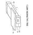
- Fig. 1A illustrates the disposal of the aforementioned first and second circuit boards. Because the DMD 102 arranged on the first board B 1 has to be perpendicular to the light path (symbolized by L) of the projection lens 104, the first circuit board B 1 is set perpendicular to the light path L. Because conventional projectors are designed to be flat, the space for the first and second circuit boards B 1 and B 2 are limited and thus the second circuit board B 2 has to be perpendicular to the first circuit board B 1 (as that shown in Fig. 1A ) to improve space utilization. The first and second circuit boards B 1 and B 2 communicate with each other by bus or connectors.
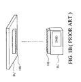
- Fig. 1B illustrates the disassembled first and second circuit boards.
- B 1 ' and B 2 ' represent B 1 and B 2 of Fig. 1A , respectively.
- Component 106 is a connector plug on the first circuit board, and its corresponding connector port symbolized by 108 is arranged on the second circuit board B 2 '.
- the conventional projector may malfunction or project inferior images due to poor contact.
- size deviation caused during fabrication exists between different Printed Circuit Boards (PCBs).
- PCBs Printed Circuit Boards
- the transmission speed of electronic signals has increased with the development of semiconductor technology.
- the connectors or bus connecting the first and second circuit boards should be produced by relatively superior quality materials.
- the cost of the projector would increase.
- high transmission speed aggravates the Electromagnetic Interface (EMI) between the bus and connectors.
- EMI Electromagnetic Interface
- An embodiment of the invention discloses a projector circuit board comprising an image receiving terminal, a central processing unit, a motor driving module, a Digital Micro-mirror Device (DMD) and a DMD control module.
- the above mentioned components may be produced by high-level semiconductor processes.
- the image receiving terminal receives an image signal and transmits the received image signal to the central processing unit.
- the central processing unit processes the received image signal.
- the motor driving module drives a motor on the basis of the processed image signal to rotate a color wheel to generate a colored beam.
- the DMD comprising a plurality of micro-mirrors, is used in reflecting the colored beam, transforming the colored beam into an image beam, and transmitting the image beam to a projection lens to project an image.
- the rotation angles of the micro-mirrors are controlled by the DMD control module coupled between the central processing unit and the DMD.
- the projector circuit board is perpendicular to a light path of the projection lens.
- the projectors comprise the aforementioned projector circuit boards.
- the projector comprises a light source, a color wheel, a motor, a reflection mirror, a projection lens and the aforementioned projector circuit board.
- the light source provides a light beam.
- the color wheel rotated by the motor transforms the light beam into a colored beam.
- the colored beam is reflected to the DMD of the projector circuit board by the reflection mirror.
- the DMD also modulates the colored beam into an image beam and transmits the image beam to the projection lens to project an image.
- the projector circuit board is perpendicular to a light path of the projection lens.
- Fig. 1A illustrates the disposal of the first and second circuit boards of conventional projectors
- Fig. 1B illustrates the disassembled first and second circuit boards of conventional projectors
- Fig. 2 illustrates the disposal of a projection lens and a projector circuit board according to an embodiment of the invention
- Fig. 3 is a block diagram showing the projector circuit board according to an embodiment of the invention.
- Fig. 4 illustrates the projector according to an embodiment of the invention.
- Fig. 2 illustrates the disposal of a projection lens and a projector circuit board of one embodiment of the invention.
- the convention projector comprises a first and a second circuit board B 1 and B 2 , but one embodiment of the invention integrates the components of B 1 and B 2 on a single projector circuit board 202.
- Components in the projector circuit board 202 are produced by high-level semiconductor processes (having lower channel width to length ratios W/L compared to the low-level semiconductor processes).
- W/L channel width to length ratios
- the DMD 204 To allow the DMD 204 to successfully transmit light to the projection lens 206, the DMD 204 has to be perpendicular to a light path L of the projection lens 206 (as that shown in Fig. 2 ). Thus, the projector circuit board 202 is perpendicular to the light path L.
- Fig. 3 is a block diagram showing a projector circuit board according to an embodiment of the invention.
- the projector circuit board 300 comprises an image receiving terminal 302, a central processing unit 304, a motor driving module 306, a DMD 308 and a DMD control module 310.
- the components of the projector circuit board 300 are produced by high-level semiconductor processes, and thus the size of the projector circuit board 300 is much smaller than the first and second circuit boards B 1 and B 2 shown in Fig. 1A .
- the image receiving terminal 302 receives an image signal 312 and transmits the received image signal to the central processing unit 304.
- the central processing unit 304 processes the received image signal and then sends the processed image signal to the motor driving module 306.
- the motor driving module 306 drives a motor (outside the projector circuit board and not shown in Fig. 3 ) to rotate a color wheel (outside the projector circuit board and not shown in Fig. 3 ) to generate a colored beam 314.
- the DMD 308 reflects the colored beam 314, modulates the colored beam 314 into an image beam 315 according to the outputs of the central processing unit 304 (the output of the central processing unit 304 is related to the image signal 312), and transmits the image beam 315 to a projection lens 3150 to project an image 3152.
- the DMD 308 comprises a plurality of micro-mirrors (not shown in Fig. 3 ) whose rotation angles are controlled by the DMD control module 310 coupled between the central processing unit 304 and the DMD 308.
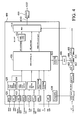
- Fig. 4 illustrates a projector according an embodiment of the invention, which adopts the projector circuit board (symbolized by 400) of an embodiment of the invention.
- the projector in addition to the projector circuit board 400, the projector further comprises a light source 402, a color wheel 404, a motor 406, a reflection mirror 408 and a projection lens 410.
- the light source 402 provides a light beam 412.
- the motor 406 is controlled by a motor driving module 418 of the projector circuit board 400 and is used in rotating the color wheel 404.
- the light beam 412 is filtered and transformed into a colored beam 414 by the color wheel 404.
- the reflection mirror 408 adjusts the path of the colored beam 414.
- the colored beam 414 is reflected by the reflection mirror 408 and received by the DMD 416 of the projector circuit board 400.
- the DMD 416 reflects the received colored beam, generates an image beam 4160 based on the received image signal, and transmits the image beam 4160 to the projection lens 410 to project an image 4102.
- the projector circuit board 400 is posed as that shown in Fig. 2 , being perpendicular to the light path L of the projection lens 410.
- the projector circuit board 400 receives a variety of image signals, including High-Definition Multimedia Interface (HDMI) signal, Transition-Minimized Differential Signaling (TMDS) signal, Graphic/ component signal, Component signal, SVideo signal, Composite signal, Recommended Standard 232 (RS232) signal, Infrared Radiation (IR) signal and Universal Serial Bus (USB) signal.
- the corresponding image connectors are HDMI connector, Digital Visual Interface DVI connector, Video Graphics Array (VGA) connector, Radio Corporation of America (RGA)*3 connector, S-Video connector, RCA*1 connector, RS232 connector, USB connector and so on.
- the received image signal is sent to the central processing unit 420 after an appropriate image processing.
- the VGA connector 422 sends the received Graphic/component signal to an analog-digital image converter 424 coupled between the VGA connector 422 and the central processing unit 420.
- the Graphic/component signal is converted from an analog form into a digital form by the analog-digital image converter 424 and then is sent to the central processing unit 420.
- the HDMI connector 426 sends the received HDMI signal to a digital signal receiving module 428 coupled between the HDMI connector 426 and the central processing unit 420.
- the digital signal receiving module 428 converts the HDMI signal into a specific signal format capable of being processed by the central processing unit 420, and sends the converted HDMI signal to the central processing unit 420.
- the central processing unit 420 is used to process the received image signal.
- the motor driving module 418 drives the motor 406 on the basis of the processed image signal.
- the central processing unit 420 further drives the DMD control module 432 to control the rotation angle of the micro-mirrors (not shown in Fig. 4 ) of the DMD 416.
- the projector circuit board 400 further comprises a direct current (DC) power supply converting module 430 generating a plurality of voltage levels for different components of the projector circuit board 400.
- DC direct current
- the term "the invention”, “the present invention” or the like does not necessarily limit the claim scope to a specific embodiment, and the reference to particularly preferred exemplary embodiments of the invention does not imply a limitation on the invention, and no such limitation is to be inferred.
- the invention is limited only by the spirit and scope of the appended claims.
- the abstract of the disclosure is provided to comply with the rules requiring an abstract, which will allow a searcher to quickly ascertain the subject matter of the technical disclosure of any patent issued from this disclosure. It is submitted with the understanding that it will not be used to interpret or limit the scope or meaning of the claims. Any advantages and benefits described may not apply to all embodiments of the invention.
Landscapes
- Engineering & Computer Science (AREA)
- Multimedia (AREA)
- Signal Processing (AREA)
- Physics & Mathematics (AREA)
- General Physics & Mathematics (AREA)
- Projection Apparatus (AREA)
- Mechanical Light Control Or Optical Switches (AREA)
Abstract
One embodiment of the invention discloses projector circuit boards comprising an image receiving terminal, a central processing unit, a motor driving module, a DMD and a DMD control module. The image receiving terminal receives an image signal and transmits the received image signal to the central processing unit. The central processing unit processes the received image signal. The motor driving module drives a motor on the basis of the processed image signal to rotate a color wheel to generate a colored beam. The DMD, comprising a plurality of micro-mirrors, is used in reflecting the colored beam, transforming the colored beam into an image beam, and transmitting the image beam to a projection lens to project an image. The rotation angles of the micro-mirrors are controlled by the DMD control module coupled between the central processing unit and the DMD. The projector circuit board is perpendicular to a light path of the projection lens.
Description
- The present invention relates generally to projector circuit boards, and more particularly, to projectors with projector circuit boards.
- In conventional techniques, projectors are designed to be a flat object. The conventional projector comprises a first circuit board and a second circuit board. The first circuit board comprises a Digital Micro-mirror Device (DMD) and a DMD control module. The second circuit board comprises a central processing unit. The first and second circuit boards are coupled to each other by bus or connectors.
-
Fig. 1A illustrates the disposal of the aforementioned first and second circuit boards. Because theDMD 102 arranged on the first board B1 has to be perpendicular to the light path (symbolized by L) of theprojection lens 104, the first circuit board B1 is set perpendicular to the light path L. Because conventional projectors are designed to be flat, the space for the first and second circuit boards B1 and B2 are limited and thus the second circuit board B2 has to be perpendicular to the first circuit board B1 (as that shown inFig. 1A ) to improve space utilization. The first and second circuit boards B1 and B2 communicate with each other by bus or connectors. -
Fig. 1B illustrates the disassembled first and second circuit boards. B1' and B2' represent B1 and B2 ofFig. 1A , respectively.Component 106 is a connector plug on the first circuit board, and its corresponding connector port symbolized by 108 is arranged on the second circuit board B2'. - Because the first and second circuit boards B1 and B2 communicate with each other via bus or connectors, the conventional projector may malfunction or project inferior images due to poor contact. Moreover, size deviation caused during fabrication exists between different Printed Circuit Boards (PCBs). When the size deviation between the first and second circuit boards B1 and B2 exceeds a tolerable value, the connection between the two circuit boards B1 and B2 may be poor (broken circuit or short), and thus the projector would not work normally.
- The transmission speed of electronic signals has increased with the development of semiconductor technology. To communicate at high speeds, the connectors or bus connecting the first and second circuit boards should be produced by relatively superior quality materials. Thus, the cost of the projector would increase. Moreover, high transmission speed aggravates the Electromagnetic Interface (EMI) between the bus and connectors.
- Novel projector circuit boards without the aforementioned drawbacks are called for.
- An embodiment of the invention discloses a projector circuit board comprising an image receiving terminal, a central processing unit, a motor driving module, a Digital Micro-mirror Device (DMD) and a DMD control module. The above mentioned components may be produced by high-level semiconductor processes. The image receiving terminal receives an image signal and transmits the received image signal to the central processing unit. The central processing unit processes the received image signal. The motor driving module drives a motor on the basis of the processed image signal to rotate a color wheel to generate a colored beam. The DMD, comprising a plurality of micro-mirrors, is used in reflecting the colored beam, transforming the colored beam into an image beam, and transmitting the image beam to a projection lens to project an image. The rotation angles of the micro-mirrors are controlled by the DMD control module coupled between the central processing unit and the DMD. The projector circuit board is perpendicular to a light path of the projection lens.
- In other embodiments of the invention, the projectors comprise the aforementioned projector circuit boards. The projector comprises a light source, a color wheel, a motor, a reflection mirror, a projection lens and the aforementioned projector circuit board. The light source provides a light beam. The color wheel rotated by the motor transforms the light beam into a colored beam. The colored beam is reflected to the DMD of the projector circuit board by the reflection mirror. In addition to reflecting the colored beam, the DMD also modulates the colored beam into an image beam and transmits the image beam to the projection lens to project an image. The projector circuit board is perpendicular to a light path of the projection lens.
- The above and other advantages will become more apparent with reference to the following description taken in conjunction with the accompanying drawings. Other objectives, features and advantages of the present invention will be further understood from the further technological features disclosed by the embodiments of the present invention wherein there are shown and described preferred embodiments of this invention, simply by way of illustration of modes best suited to carry out the invention.
- The invention can be more fully understood by reading the subsequent detailed description and examples with references made to the accompanying drawings, wherein:
-
Fig. 1A illustrates the disposal of the first and second circuit boards of conventional projectors; -
Fig. 1B illustrates the disassembled first and second circuit boards of conventional projectors; -
Fig. 2 illustrates the disposal of a projection lens and a projector circuit board according to an embodiment of the invention; -
Fig. 3 is a block diagram showing the projector circuit board according to an embodiment of the invention; and -
Fig. 4 illustrates the projector according to an embodiment of the invention. - In the following detailed description of the preferred embodiments, reference is made to the accompanying drawings which form a part hereof, and in which are shown by way of illustration specific embodiments in which the invention may be practiced. In this regard, directional terminology, such as "top," "bottom," "front," "back," etc., is used with reference to the orientation of the Figure(s) being described. The components of the present invention can be positioned in a number of different orientations. As such, the directional terminology is used for purposes of illustration and is in no way limiting. On the other hand, the drawings are only schematic and the sizes of components may be exaggerated for clarity. It is to be understood that other embodiments may be utilized and structural changes may be made without departing from the scope of the present invention. Also, it is to be understood that the phraseology and terminology used herein are for the purpose of description and should not be regarded as limiting. The use of "including," "comprising," or "having" and variations thereof herein is meant to encompass the items listed thereafter and equivalents thereof as well as additional items. Unless limited otherwise, the terms "connected," "coupled, " and "mounted" and variations thereof herein are used broadly and encompass direct and indirect connections, couplings, and mountings. Similarly, the terms "facing," "faces" and variations thereof herein are used broadly and encompass direct and indirect facing, and "adjacent to" and variations thereof herein are used broadly and encompass directly and indirectly "adjacent to". Therefore, the description of "A" component facing "B" component herein may contain the situations that "A" component directly faces "B" component or one or more additional components are between "A" component and "B" component. Also, the description of "A" component "adjacent to" "B" component herein may contain the situations that "A" component is directly "adjacent to" "B" component or one or more additional components are between "A" component and "B" component. Accordingly, the drawings and descriptions will be regarded as illustrative in nature and not as restrictive.
-
Fig. 2 illustrates the disposal of a projection lens and a projector circuit board of one embodiment of the invention. ComparingFig. 1A withFig. 2 , the convention projector comprises a first and a second circuit board B1 and B2, but one embodiment of the invention integrates the components of B1 and B2 on a singleprojector circuit board 202. Components in theprojector circuit board 202 are produced by high-level semiconductor processes (having lower channel width to length ratios W/L compared to the low-level semiconductor processes). Thus the size of theprojector circuit board 202 is dramatically reduced and can be installed in the limited space of the projector. To allow theDMD 204 to successfully transmit light to theprojection lens 206, theDMD 204 has to be perpendicular to a light path L of the projection lens 206 (as that shown inFig. 2 ). Thus, theprojector circuit board 202 is perpendicular to the light path L. -
Fig. 3 is a block diagram showing a projector circuit board according to an embodiment of the invention. Theprojector circuit board 300 comprises animage receiving terminal 302, acentral processing unit 304, amotor driving module 306, aDMD 308 and aDMD control module 310. The components of theprojector circuit board 300 are produced by high-level semiconductor processes, and thus the size of theprojector circuit board 300 is much smaller than the first and second circuit boards B1 and B2 shown inFig. 1A . Theimage receiving terminal 302 receives animage signal 312 and transmits the received image signal to thecentral processing unit 304. Thecentral processing unit 304 processes the received image signal and then sends the processed image signal to themotor driving module 306. On the basis of the processed image signal, themotor driving module 306 drives a motor (outside the projector circuit board and not shown inFig. 3 ) to rotate a color wheel (outside the projector circuit board and not shown inFig. 3 ) to generate acolored beam 314. TheDMD 308 reflects thecolored beam 314, modulates thecolored beam 314 into animage beam 315 according to the outputs of the central processing unit 304 (the output of thecentral processing unit 304 is related to the image signal 312), and transmits theimage beam 315 to aprojection lens 3150 to project an image 3152. TheDMD 308 comprises a plurality of micro-mirrors (not shown inFig. 3 ) whose rotation angles are controlled by theDMD control module 310 coupled between thecentral processing unit 304 and theDMD 308. -
Fig. 4 illustrates a projector according an embodiment of the invention, which adopts the projector circuit board (symbolized by 400) of an embodiment of the invention. Referring toFig. 4 , in addition to theprojector circuit board 400, the projector further comprises alight source 402, a color wheel 404, amotor 406, a reflection mirror 408 and aprojection lens 410. Thelight source 402 provides alight beam 412. Themotor 406 is controlled by amotor driving module 418 of theprojector circuit board 400 and is used in rotating the color wheel 404. Thelight beam 412 is filtered and transformed into acolored beam 414 by the color wheel 404. The reflection mirror 408 adjusts the path of thecolored beam 414. Thecolored beam 414 is reflected by the reflection mirror 408 and received by theDMD 416 of theprojector circuit board 400. TheDMD 416 reflects the received colored beam, generates animage beam 4160 based on the received image signal, and transmits theimage beam 4160 to theprojection lens 410 to project animage 4102. Theprojector circuit board 400 is posed as that shown inFig. 2 , being perpendicular to the light path L of theprojection lens 410. - In the embodiment shown in
Fig. 4 , theprojector circuit board 400 receives a variety of image signals, including High-Definition Multimedia Interface (HDMI) signal, Transition-Minimized Differential Signaling (TMDS) signal, Graphic/ component signal, Component signal, SVideo signal, Composite signal, Recommended Standard 232 (RS232) signal, Infrared Radiation (IR) signal and Universal Serial Bus (USB) signal. The corresponding image connectors are HDMI connector, Digital Visual Interface DVI connector, Video Graphics Array (VGA) connector, Radio Corporation of America (RGA)*3 connector, S-Video connector, RCA*1 connector, RS232 connector, USB connector and so on. In some embodiments, the received image signal is sent to thecentral processing unit 420 after an appropriate image processing. For example, when the received image signal is a Graphic/component signal, theVGA connector 422 sends the received Graphic/component signal to an analog-digital image converter 424 coupled between theVGA connector 422 and thecentral processing unit 420. The Graphic/component signal is converted from an analog form into a digital form by the analog-digital image converter 424 and then is sent to thecentral processing unit 420. When the image signal is a HDMI signal, theHDMI connector 426 sends the received HDMI signal to a digitalsignal receiving module 428 coupled between theHDMI connector 426 and thecentral processing unit 420. The digitalsignal receiving module 428 converts the HDMI signal into a specific signal format capable of being processed by thecentral processing unit 420, and sends the converted HDMI signal to thecentral processing unit 420. - The
central processing unit 420 is used to process the received image signal. Themotor driving module 418 drives themotor 406 on the basis of the processed image signal. Thecentral processing unit 420 further drives theDMD control module 432 to control the rotation angle of the micro-mirrors (not shown inFig. 4 ) of theDMD 416. - Referring to
Fig. 4 , theprojector circuit board 400 further comprises a direct current (DC) powersupply converting module 430 generating a plurality of voltage levels for different components of theprojector circuit board 400. - The foregoing description of the preferred embodiments of the invention has been presented for purposes of illustration and description. It is not intended to be exhaustive or to limit the invention to the precise form or to exemplary embodiments disclosed. Accordingly, the foregoing description should be regarded as illustrative rather than restrictive. Obviously, many modifications and variations will be apparent to practitioners skilled in this art. The embodiments are chosen and described in order to best explain the principles of the invention and its best mode practical application, thereby to enable persons skilled in the art to understand the invention for various embodiments and with various modifications as are suited to the particular use or implementation contemplated. It is intended that the scope of the invention be defined by the claims appended hereto and their equivalents in which all terms are meant in their broadest reasonable sense unless otherwise indicated. Therefore, the term "the invention", "the present invention" or the like does not necessarily limit the claim scope to a specific embodiment, and the reference to particularly preferred exemplary embodiments of the invention does not imply a limitation on the invention, and no such limitation is to be inferred. The invention is limited only by the spirit and scope of the appended claims. The abstract of the disclosure is provided to comply with the rules requiring an abstract, which will allow a searcher to quickly ascertain the subject matter of the technical disclosure of any patent issued from this disclosure. It is submitted with the understanding that it will not be used to interpret or limit the scope or meaning of the claims. Any advantages and benefits described may not apply to all embodiments of the invention. It should be appreciated that variations may be made in the embodiments described by persons skilled in the art without departing from the scope of the present invention as defined by the following claims. Moreover, no element and component in the present disclosure is intended to be dedicated to the public regardless of whether the element or component is explicitly recited in the following claims.
Claims (12)
- A projector circuit board, comprising:an image receiving terminal, receiving an image signal;a central processing unit, processing the received image signal;a motor driving module, rotating a color wheel on the basis of the processed image signal to generate a colored beam;a Digital Micro-mirror Device, comprising a plurality of micro-mirrors, reflecting the colored beam, modulating the colored beam into an image beam on the basis of the image signal, and transmitting the image beam to a projection lens to project an image; anda Digital Micro-mirror Device control module, coupling to the central processing unit and the Digital Micro-mirror Device, and controlling rotation angles of the micro-mirrors on the basis of the image signal;wherein the projector circuit board is perpendicular to a light path of the projection lens.
- The projector circuit board as claimed in claim 1, further comprising a direct current power supply converting module generating a plurality of voltage levels for different components of the projector circuit board.
- The projector circuit board as claimed in claim 1, wherein the image receiving terminal is implemented by a Video Graphics Array connector.
- The projector circuit board as claimed in claim 3, further comprising an analog-digital image converter coupling to the Video Graphics Array connector and the central processing unit to convert the image signal received by the Video Graphics Array connector from an analog form to a digital form.
- The projector circuit board as claimed in claim 1, wherein the image receiving terminal is implemented by a High-Definition Multimedia Interface connector.
- The projector circuit board as claimed in claim 5, further comprising a digital image signal receiving module coupling to the High-Definition Multimedia Interface connector and the central processing unit to convert the image signal received by the High-Definition Multimedia Interface connector to a specific signal format capable of being processed by the central processing unit.
- A projector, comprising:a light source, providing a light beam;a motor;a color wheel, rotated by the motor to transform the light beam to a colored beam;a projection lens; anda projector circuit board, comprising:wherein the projector circuit board is perpendicular to a light path of the projection lens.an image receiving terminal, receiving an image signal;a central processing unit, processing the image signal received by the image receiving terminal;a motor driving module, driving the motor on the basis of the processed image signal;a Digital Micro-mirror Device, comprising a plurality of micro-mirrors, reflecting the colored beam, modulating the colored beam into an image beam on the basis of the image signal, and transmitting the image beam to the projection lens to project an image; anda Digital Micro-mirror Device control module, coupling to the central processing unit and the Digital Micro-mirror Device, and controlling rotation angles of the micro-mirrors;
- The projector as claimed in claim 7, further comprising a direct current power supply converting module generating a plurality of voltage levels for different components of the projector circuit board.
- The projector as claimed in claim 7, wherein the image receiving terminal is implemented by a Video Graphics Array connector.
- The projector as claimed in claim 9, further comprising an analog-digital image converter coupling to the Video Graphics Array connector and the central processing unit to convert the image signal received by the Video Graphics Array connector from an analog form to a digital form.
- The projector as claimed in claim 7, wherein the image receiving terminal is implemented by a High-Definition Multimedia Interface connector.
- The projector as claimed in claim 11, further comprising a digital image signal receiving module coupling to the High-Defmition Multimedia Interface connector and the central processing unit to convert the image signal received by the High-Definition Multimedia Interface connector to a specific signal format that capable of being processed by the central processing unit.
Applications Claiming Priority (1)
| Application Number | Priority Date | Filing Date | Title |
|---|---|---|---|
| TW096130295A TWI351575B (en) | 2007-08-16 | 2007-08-16 | Projector circuit board and projector |
Publications (1)
| Publication Number | Publication Date |
|---|---|
| EP2026125A1 true EP2026125A1 (en) | 2009-02-18 |
Family
ID=40021455
Family Applications (1)
| Application Number | Title | Priority Date | Filing Date |
|---|---|---|---|
| EP08008123A Withdrawn EP2026125A1 (en) | 2007-08-16 | 2008-04-28 | Projector and projector circuit board thereof |
Country Status (3)
| Country | Link |
|---|---|
| US (1) | US7883215B2 (en) |
| EP (1) | EP2026125A1 (en) |
| TW (1) | TWI351575B (en) |
Families Citing this family (7)
| Publication number | Priority date | Publication date | Assignee | Title |
|---|---|---|---|---|
| US8562149B2 (en) * | 2010-05-21 | 2013-10-22 | Delta Electronics, Inc. | Flexibly connectable digital micromirror device module and projecting apparatus employing same |
| CN103869586B (en) * | 2012-12-18 | 2017-02-08 | 中强光电股份有限公司 | Projection device |
| US9803997B2 (en) * | 2013-07-26 | 2017-10-31 | Bei Sensors & Systems Company, Inc. | System and method for determining absolute angular position of a rotating member |
| US9389283B2 (en) | 2013-07-26 | 2016-07-12 | Sensata Technologies, Inc. | System and method for converting output of sensors to absolute angular position of a rotating member |
| TWI556017B (en) | 2014-10-16 | 2016-11-01 | 信泰光學(深圳)有限公司 | Pico projector |
| WO2018135462A1 (en) * | 2017-01-17 | 2018-07-26 | 日本精機株式会社 | Display device |
| CN110855963B (en) * | 2018-08-21 | 2022-03-08 | 视联动力信息技术股份有限公司 | Video data projection method and device |
Citations (4)
| Publication number | Priority date | Publication date | Assignee | Title |
|---|---|---|---|---|
| US4680579A (en) * | 1983-09-08 | 1987-07-14 | Texas Instruments Incorporated | Optical system for projection display using spatial light modulator device |
| US6155687A (en) * | 1999-07-16 | 2000-12-05 | Infocus Corporation | Light guide for use in a color wheel display synchronization apparatus and method |
| US20060139730A1 (en) * | 2004-12-23 | 2006-06-29 | Oehler Peter R | Illumination system with compact turning prism and projection system using same |
| WO2007017297A1 (en) * | 2005-08-10 | 2007-02-15 | Tte Technology, Inc. | A system and method for generating images |
Family Cites Families (3)
| Publication number | Priority date | Publication date | Assignee | Title |
|---|---|---|---|---|
| KR100190766B1 (en) * | 1996-06-24 | 1999-06-01 | 김영환 | Switched Capacitor Digital-to-Analog Converter Reduces Harmonic Distortion |
| KR100629534B1 (en) | 2004-02-12 | 2006-09-27 | 엘지전자 주식회사 | Color error correction method and device according to temperature change |
| JP4017167B2 (en) * | 2004-06-07 | 2007-12-05 | フジノン株式会社 | Projection display device |
-
2007
- 2007-08-16 TW TW096130295A patent/TWI351575B/en active
-
2008
- 2008-04-03 US US12/061,674 patent/US7883215B2/en active Active
- 2008-04-28 EP EP08008123A patent/EP2026125A1/en not_active Withdrawn
Patent Citations (4)
| Publication number | Priority date | Publication date | Assignee | Title |
|---|---|---|---|---|
| US4680579A (en) * | 1983-09-08 | 1987-07-14 | Texas Instruments Incorporated | Optical system for projection display using spatial light modulator device |
| US6155687A (en) * | 1999-07-16 | 2000-12-05 | Infocus Corporation | Light guide for use in a color wheel display synchronization apparatus and method |
| US20060139730A1 (en) * | 2004-12-23 | 2006-06-29 | Oehler Peter R | Illumination system with compact turning prism and projection system using same |
| WO2007017297A1 (en) * | 2005-08-10 | 2007-02-15 | Tte Technology, Inc. | A system and method for generating images |
Also Published As
| Publication number | Publication date |
|---|---|
| TW200909970A (en) | 2009-03-01 |
| US20090046256A1 (en) | 2009-02-19 |
| US7883215B2 (en) | 2011-02-08 |
| TWI351575B (en) | 2011-11-01 |
Similar Documents
| Publication | Publication Date | Title |
|---|---|---|
| US7883215B2 (en) | Projector and projector circuit board thereof | |
| US7406607B2 (en) | Controller for a host device and a monitoring device connected on the basis of DVI standard | |
| CN105519093B (en) | Focus tracking, the remote control with the focus tracking are with burnt system and aircraft | |
| CN111711804B (en) | A digital micromirror device driver chip FPGA prototype verification platform | |
| EP0910203A2 (en) | Printer having universal image port and related system and method | |
| JP2013080229A (en) | Configurable imaging system | |
| EP2746849B1 (en) | Projection apparatus comprising parallel circuit borads | |
| EP1096366A3 (en) | Projection display apparatus and systems | |
| EP2166530A2 (en) | Liquid crystal display and display system comprising the same | |
| CN112866660B (en) | Projector control method and projector | |
| US10762024B2 (en) | Signal transmission device and signal transmission method | |
| CN113923426A (en) | Laser projector driving device and laser projector | |
| TW202110169A (en) | Circuit and method for use in a first display device to facilitate communication with a second display device, and display communication system | |
| CN201449511U (en) | Laser projection system | |
| US11176907B2 (en) | Video data displaying device | |
| US20040207767A1 (en) | Image transmission system of rear projection television | |
| CN101393381A (en) | Projector circuit board and projector | |
| CN221841622U (en) | High definition VR display control panel | |
| US20120154362A1 (en) | Projection system and projection apparatus | |
| US20110075056A1 (en) | Projection Display Apparatus | |
| US20250150561A1 (en) | Projection system and control method | |
| CN212135498U (en) | Image processing apparatus for digital cinema projector | |
| CN210297885U (en) | Projection control circuit and projector | |
| US7830996B2 (en) | Display apparatus and control method thereof | |
| US20110255016A1 (en) | Notebook computer with projection function |
Legal Events
| Date | Code | Title | Description |
|---|---|---|---|
| PUAI | Public reference made under article 153(3) epc to a published international application that has entered the european phase |
Free format text: ORIGINAL CODE: 0009012 |
|
| AK | Designated contracting states |
Kind code of ref document: A1 Designated state(s): AT BE BG CH CY CZ DE DK EE ES FI FR GB GR HR HU IE IS IT LI LT LU LV MC MT NL NO PL PT RO SE SI SK TR |
|
| AX | Request for extension of the european patent |
Extension state: AL BA MK RS |
|
| AKX | Designation fees paid | ||
| STAA | Information on the status of an ep patent application or granted ep patent |
Free format text: STATUS: THE APPLICATION IS DEEMED TO BE WITHDRAWN |
|
| 18D | Application deemed to be withdrawn |
Effective date: 20090819 |
|
| REG | Reference to a national code |
Ref country code: DE Ref legal event code: 8566 |