EP2026037A2 - Navigation system and corresponding method for gyrocompass alignment using dynamically calibrated sensor data and an iterative extended kalman filter - Google Patents
Navigation system and corresponding method for gyrocompass alignment using dynamically calibrated sensor data and an iterative extended kalman filter Download PDFInfo
- Publication number
- EP2026037A2 EP2026037A2 EP08162274A EP08162274A EP2026037A2 EP 2026037 A2 EP2026037 A2 EP 2026037A2 EP 08162274 A EP08162274 A EP 08162274A EP 08162274 A EP08162274 A EP 08162274A EP 2026037 A2 EP2026037 A2 EP 2026037A2
- Authority
- EP
- European Patent Office
- Prior art keywords
- sensor data
- data
- processing device
- kalman filter
- dynamically
- Prior art date
- Legal status (The legal status is an assumption and is not a legal conclusion. Google has not performed a legal analysis and makes no representation as to the accuracy of the status listed.)
- Withdrawn
Links
- 238000000034 method Methods 0.000 title claims abstract description 27
- 238000012545 processing Methods 0.000 claims abstract description 50
- 238000005259 measurement Methods 0.000 claims abstract description 31
- 239000011159 matrix material Substances 0.000 claims description 26
- 238000006243 chemical reaction Methods 0.000 claims description 20
- 230000001133 acceleration Effects 0.000 claims description 4
- 238000012935 Averaging Methods 0.000 claims description 3
- 230000005484 gravity Effects 0.000 description 6
- 230000009021 linear effect Effects 0.000 description 6
- 230000009022 nonlinear effect Effects 0.000 description 6
- 238000013459 approach Methods 0.000 description 2
- 238000010586 diagram Methods 0.000 description 2
- NCGICGYLBXGBGN-UHFFFAOYSA-N 3-morpholin-4-yl-1-oxa-3-azonia-2-azanidacyclopent-3-en-5-imine;hydrochloride Chemical compound Cl.[N-]1OC(=N)C=[N+]1N1CCOCC1 NCGICGYLBXGBGN-UHFFFAOYSA-N 0.000 description 1
- 238000004364 calculation method Methods 0.000 description 1
- 238000012937 correction Methods 0.000 description 1
- 238000005312 nonlinear dynamic Methods 0.000 description 1
- 230000035945 sensitivity Effects 0.000 description 1
- 230000033772 system development Effects 0.000 description 1
- 230000007704 transition Effects 0.000 description 1
Images


Classifications
-
- G—PHYSICS
- G01—MEASURING; TESTING
- G01C—MEASURING DISTANCES, LEVELS OR BEARINGS; SURVEYING; NAVIGATION; GYROSCOPIC INSTRUMENTS; PHOTOGRAMMETRY OR VIDEOGRAMMETRY
- G01C21/00—Navigation; Navigational instruments not provided for in groups G01C1/00 - G01C19/00
- G01C21/10—Navigation; Navigational instruments not provided for in groups G01C1/00 - G01C19/00 by using measurements of speed or acceleration
- G01C21/12—Navigation; Navigational instruments not provided for in groups G01C1/00 - G01C19/00 by using measurements of speed or acceleration executed aboard the object being navigated; Dead reckoning
- G01C21/16—Navigation; Navigational instruments not provided for in groups G01C1/00 - G01C19/00 by using measurements of speed or acceleration executed aboard the object being navigated; Dead reckoning by integrating acceleration or speed, i.e. inertial navigation
- G01C21/165—Navigation; Navigational instruments not provided for in groups G01C1/00 - G01C19/00 by using measurements of speed or acceleration executed aboard the object being navigated; Dead reckoning by integrating acceleration or speed, i.e. inertial navigation combined with non-inertial navigation instruments
- G01C21/1654—Navigation; Navigational instruments not provided for in groups G01C1/00 - G01C19/00 by using measurements of speed or acceleration executed aboard the object being navigated; Dead reckoning by integrating acceleration or speed, i.e. inertial navigation combined with non-inertial navigation instruments with electromagnetic compass
-
- G—PHYSICS
- G01—MEASURING; TESTING
- G01C—MEASURING DISTANCES, LEVELS OR BEARINGS; SURVEYING; NAVIGATION; GYROSCOPIC INSTRUMENTS; PHOTOGRAMMETRY OR VIDEOGRAMMETRY
- G01C25/00—Manufacturing, calibrating, cleaning, or repairing instruments or devices referred to in the other groups of this subclass
- G01C25/005—Manufacturing, calibrating, cleaning, or repairing instruments or devices referred to in the other groups of this subclass initial alignment, calibration or starting-up of inertial devices
Definitions
- Navigation systems are one example of nonlinear dynamic systems.
- One of the problems associated with navigation system development is the estimation of the various states of the dynamic system. Such estimations typically utilize navigation system software.
- the extended Kalman filter (EKF) has been used within navigation system software to make such estimations.
- the EKF applies a Taylor series expansion for nonlinear system and observation equations, and utilizes first order terms to apply the well-known linear Kalman filter theory, where the probability density function (PDF) is assumed to be Gaussian.
- PDF probability density function
- the EKF has shown several limitations.
- One of the limitations is that only small errors are allowed to be input into the EKF. Otherwise, in the presence of nonlinear error behavior, the first-order approximations can cause biased solutions and inconsistencies in updating of the covariance matrix, which can lead to filter instability. While second-order versions of the EKF exist, their increased implementation and computation complexity tend to prohibit their use.
- a popular technique to improve the first-order approach is the iterated EKF, which effectively iterates the EKF equations at the current time observation by redefining the nominal state estimate and re-linearizing the measurement equations.
- the iterated EKF is capable of providing better performance than the basic EKF, especially in the case of significant nonlinearity in the measurement function.
- INS inertial navigation systems
- GPS range measuring device and an INS which provides data relating to an angular velocity, velocity, and azimuth measuring, which are used in combination to measure motion of a mobile object (e.g., airplane).
- the navigation systems also contain range error estimating devices. Based on the output of the error estimating devices, position of the mobile object can be determined.
- the error estimating devices are sometimes implemented using Kalman filters and averaging processes.
- the outputs of the various measuring devices are thereby corrected using Kalman filters and the like so that the position of the mobile object can be estimated with a relatively high level of accuracy without using a high precision sensor.
- Kalman filters due to the nature of high noise, nonlinear effects, and imprecise measurements associated with low cost MEMS sensors, traditional EKF estimation will degrade with time and become unreliable. Therefore, the accuracy of the INS is limited, especially when GPS data is not available.
- Most nonlinear Kalman filters can be used to improve an estimation error, however, such implementations are difficult. More specifically, such implementations are difficult to tune and additionally it is difficult to switch estimation schemes because the nonlinear effect only shows up in certain scenarios.
- IMU inertial measurement unit
- the present invention includes a navigation system for an aircraft that includes an inertial measurement device configured to provide a first set of sensor data relating to operation of the aircraft and a positioning unit configured to provide a second set of data relating to position of the aircraft.
- the navigation system includes a processing device configured to receive the data sets provided by the inertial measurement device and the positioning device, and the processing device is configured to dynamically calibrate the received first data set, the processing device includes a Kalman filter, and the processing device is further configured to generate a gyrocompass alignment using the first dynamically calibrated first data set, the second data set, and the Kalman filter.
- the inertial measurement device includes microelectromechanical systems (MEMS) based accelerometers and gyros.
- MEMS microelectromechanical systems
- the processing device is configured to real-time average the first set of sensor data, the processing device is configured to estimate a heading based on the dynamically calibrated first set of sensor data, and the processing device is configured to generate a gyrocompass alignment using the estimated heading.
- the processing device is configured to initialize a conversion matrix using at least a portion of the estimated heading and the processing device is further configured to initialize the Kalman filter using the initialized conversion matrix.
- the processing device is configured to estimate sensor error using the real-time averaged first set of sensor data, and the processing device is further configured to correct the estimated sensor error with known gravitational acceleration and earth rate values to generate the dynamically calibrated first set of sensor data.
- the invention includes a method for gyrocompass alignment, the method including receiving sensor data from a plurality of sensors, dynamically calibrating at least a portion of the sensor data, and generating gyrocompass alignment information based on the dynamically calibrated sensor data.
- the method includes displaying a navigation output based on the generated gyrocompass alignment information.
- the method includes estimating a heading based on the dynamically calibrated sensor data, initializing a conversion matrix using at least a portion of the estimated heading, and initializing an iterated extended Kalman filter using the initialized conversion matrix.
- the invention provides a system and method for gyrocompass alignment using dynamically calibrated sensor data.
- FIGURE 1 is a block diagram of a multiple input navigation system incorporating an iterated Kalman filter operable to provide a position solution in a number of operating modes;
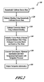
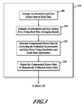
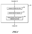
- FIGURES 2-5 are flowcharts of a method of generating navigation output in accordance with an embodiment of the invention
- FIGURE 1 is a block diagram of a navigation system 50 which includes a processing device 51 that includes a navigation processor 52 configured to dynamically switch between Kalman filter implementations in order to at least partially address the problems associated with processing of non-linear errors as described above.
- the navigation system 50 is used in a mobile object (not shown) such as an aircraft or a spacecraft.
- dynamically switching between Kalman filter implementations is utilized to address problems associated with gyroscope compass alignment times.
- this dynamic switching provides the navigation processor 52 with a capability to counter non-linear effects in received inertial data when estimating a position and reduce gyroscope compass alignment times for the navigation system 50.
- gyrocompass alignment times are reduced by using dynamic calibration of accelerometer and gyro data, estimation of heading based on the dynamically calibrated data, initialization of a conversion matrix using estimated heading information, and initialization of an iterated extended Kalman filter (IEKF) with the conversion matrix, further described with reference to FIGURES 2-5 .
- INKF extended Kalman filter
- the navigation system 50 includes an inertial measurement device with inertial sensors 60 having, for example, MEMS-based gyroscopes and accelerometers.
- the navigation system 50 also includes other sensors such as a barometric altimeter 62, a GPS receiver positioning unit 64, a true airspeed (TAS) indicator 66, and a magnetometer 67. Other types and fewer or greater numbers of sensors may also be included in the navigation system 50 in some examples.
- the navigation system 50 also includes a gravitation input 68 and an earth rate input 69.
- the gravitation input 68 is a digitally stored world gravitational map that is accessible by the processing device 51 in one example.
- gyros included in the inertial sensors 60 record components (x, y, and z) of earth-rate and accelerometers included in the inertial sensors 60 record components (x, y, and z) of gravity.
- the value of gravity used in the gravitation input 68 is determined using gravitational information associated with a standard reference frame such as the World Geodetic System (WGS), revision WGS 84.
- the earth-rate is a constant regardless of where the navigation system 50 is located on the surface of the earth.
- the earth-rate input 69 and the gravitation input 68 are used for calibration to determine a "bias" or "scale-factor" of the inertial sensors 60.
- the processing device 51 can then generate compensated sensor data based on information from the inertial sensors 60, the gravitation input 68, and the earth-rate input 69. Components (x, y, and z) of the compensated gyro and accelerometer sensor data are then used by the processing device 51 to generate a heading.
- the processing device 51 also includes an input processing unit 70 that processes the data from the listed sensing devices and outputs the combined sensor data 72 to the navigation processor 52.
- the navigation processor 52 utilizes an iterated, extended Kalman filter (IEKF) 74 to remove errors from the combined sensor data 72 and provide accurate navigational output data 78 to a navigation display device 80 and back into the input processing unit 70.
- the IEKF 74 can selectively operate in a local mode or a global mode.
- the Kalman filter 74 also provides inertial sensor corrections 82 back into the input processing unit 70.
- the input processing unit 70 also processes the data from the inertial sensors 60 and outputs a set of combined sensor data 72 to the navigation processor 52.
- sensor data is not combined before being output to the navigation processor 52.
- navigation processor 52 uses the IEKF 74 in a Global iterated, extended Kalman filter (G-IEKF) mode when gyrocompass alignment is being performed
- G-IEKF Global iterated, extended Kalman filter
- Kalman filter 74 is initialized with at least position and velocity error states, in one embodiment, and incorporates an estimation technique which provides an estimate of navigation system errors.
- the estimation technique includes a calculation of a Kalman gain matrix which relates an accuracy of a current measurement received from one or more of the sensors 60, 62, 64, 66, and 67 to that of the previous estimates of errors associated with the sensors 60, 62, 64, 66, and 67.
- a wheel sensor signal 84 received by the navigation system 50 is indicative of whether an aircraft (not shown) incorporating the navigation system 50 is on the ground.
- the wheel sensor signal 84 in the illustrated embodiment, is provided to Kalman filter 74.
- An indication that the aircraft is on the ground is sometimes referred to as a stationary case, and gyrocompass alignment is typically performed when the aircraft is stationary.
- the Kalman filter 74 utilizes a state of the wheel sensor signal 84 to switch to and from iteration of both time updating error states and measurement updating error states (a global iterated, extended Kalman filter (G-IEKF) mode) of sensors 60, 62, 64, 66, and 67 and iteration of only the measurement updating error states (an iterated, extended Kalman filter (IEKF) mode) of sensors 60, 62, 64, 66, and 67.
- G-IEKF global iterated, extended Kalman filter
- IEEEKF extended Kalman filter
- navigation system 50 is a highly accurate, real-time system that incorporates the Kalman filter (IEKF) 74.
- the IEKF 74 as further described herein, is configured to operate as both a linear basic Kalman filter, performing a single iteration, as well as a nonlinear Kalman filter performing several iterations.
- the determination between a single iteration and multiple iterations is based upon one or more conditions received, for example, at the input processing unit 70.
- the determination may also be based upon results from residuals, covariance matrix values, differences between error states, or one or more signals received at the input processing unit 70.
- the system 50 is configured to dynamically characterize the nonlinear tendencies and adapt the Kalman filter 74 based on the convergence information. In one example, the system 50 is also configured to switch the mode between stationary and non-stationary cases to adapt the Kalman filter 74 between a G-IEKF mode of operation and an IEKF mode of operation.
- the processing device 51 is configured to receive a first set of sensor data from the inertial measurement device sensors 60 and to receive a second set of data from the GPS receiver positioning unit 64.
- the processing device 51 is configured to dynamically calibrate the first set of sensor data provided by the inertial measurement device sensors 60, such as measurement data received from MEMS based accelerometers and gyros.
- the processing device 51 is further configured to generate a gyrocompass alignment using the first dynamically calibrated first data set, the second data set, and the IEKF 74.
- the gyro-compass alignment process is performed while a mobile object (not shown) that includes the navigation system 50 is stationary. Heading is located within a range (a few degrees depending on the inertial sensors 60 used) in coarse-alignment mode. Then, fine-mode is used to further refine the accuracy of the heading. The accuracy is determined to within approximately 0.01 degrees with expensive IMUs. DCAL coarse and fine-mode can be used with inexpensive IMUs, such as MEMS based IMUs, in an additional example.
- the gyro-compass alignment is generally performed in the order of (1) DCAL-coarse mode; (2) IEKF coarse mode; and (3) IEKF fine mode. In an example, DCAL coarse mode includes real-time calibration.
- DCAL coarse mode also includes reversing a trajectory generation (TGEN) engine or a similar type of engine to find heading information with DCAL aided sensor data.
- TGEN trajectory generation
- a TGEN engine is used to generate ideal sensor data according to a target trajectory that includes a stationary case.
- heading is located using DCAL coarse mode followed directly by EKF fine mode.
- heading is located using EKF coarse mode followed by EKF fine mode. The combination of modes used for heading location may vary to suit the needs of differing applications.
- the processing device 51 is configured to real-time average the first set of sensor data, estimate a heading based on the dynamically calibrated first set of sensor data, initialize a body to local conversion matrix using at least a portion of the estimated heading, and initialize the IEKF 74 using the initialized body to local conversion matrix.
- body frame is defined in relation to an airplane (not shown) in which the navigation system 50 is included (x-nose, y-wing, z-down) while local frame is defined with local directions (x-north, y-east, z-down).
- the conversion matrix is initialized using estimated heading information rather than simply averaged accelerometer data.
- the processing device 51 is further configured to estimate sensor error using the real-time averaged first set of sensor data and is further configured to correct the estimated sensor error with the known gravitational acceleration input 68 and earth rate input 69.
- the navigation display device 80 is configured to display navigation information using the generated gyrocompass alignment.
- Kalman filter 74 By utilizing the Kalman filter 74, the nonlinear effects associated with various error states are reduced and the nonlinear Kalman filter 74 can be dynamically turned on or off based on the convergence conditions. Stated differently, Kalman filter 74 within system 50 will adapt and perform iterations as either a Global iterated, extended Kalman filter or as an iterated, extended Kalman filter based on sensor behavior or other signals received by system 50.
- One such sensor behavior analysis includes a comparison of a current error state vector with a previous error state vector. More specifically, comparing a gyroscope data value and error value from a first and second error state iteration is utilized by the processing device 51 in one embodiment to determine whether and in which mode the Kalman filter 74 will operate.
- Heading error becomes smaller with multiple iterations of the Kalman filter 74.
- the processing device 51 determines if non-linear effects are reduced to predetermined acceptable levels.
- Such an analysis includes a decision as to whether the sensor behavior is linear or non-linear as a function of error magnitude, and may further include a calibration of the gyroscope nonlinearity with an iteration time of the Kalman filter 74. Such embodiments are thought to improve the accuracy of position determinations made by system 50.
- x is the state vector
- F is the state transition matrix
- P is the covariance matrix
- Q is the covariance of dynamic disturbance noise
- R is the covariance of measurement noise
- H is the measurement sensitivity matrix
- K is the Kalman gain.
- the index "i” is used for iteration and k is the time related index.
- both time and measurement equations are updated during iteration. Due to the back propagation of the state estimate, a global iterated, extended Kalman filter implementation is utilized, in one embodiment, for gyrocompass alignment.
- the basic formulas for the global iterated, extended Kalman filter implementation are similar to those of a local extended Kalman filter implementation except that for global iteration both time prediction equations (1)-(2) and measurement equations (4)-(6) are updated. While keeping the time step as "virtual time" during global iteration, the number of measurements can be reduced for a stationary case and the alignment time will be much shorter when compared with that of the traditional extended Kalman filter approach. When convergence is achieved, iteration is stopped.
- Kalman filter 74 reduces gyroscope compass alignment time by iterating both time updating equations and measurement updating equations. Such iterations are substantially equivalent to using a short time step when utilizing a basic extended Kalman filter. Due to noise levels present in the data from various inexpensive sensors, for example, data from micro electromechanical systems (MEMS) based inertial systems, the time step for the extended Kalman filter such as the Kalman filter 74 are usually selected to be approximately 1 second. However, more closely spaced time steps are used in some examples. Such a time step may be used to measure nonlinearity for the sensor data during calibration. In an example, calibration is performed dynamically as is more fully described with reference to FIGURE 3 .
- MEMS micro electromechanical systems
- Another criterion to measure the nonlinearity is the comparison of a current error state vector with a previous error state vector. For example, a first iteration for an iterated, extended Kalman filter is identical with the basic extended Kalman filter. If this first iteration does not cancel the nonlinear effects of the received sensor data, more iterations will be performed by the filter.
- real-time navigation system 50 is configured with two rate processors (not shown) to accommodate these iterations.
- One rate processor is utilized for implementation of the above described Kalman filter and operates at a comparatively slow rate, while the other rate processor is a high rate processor utilized for sensor data updates.
- a for-loop is used to perform the iteration. During iterations, except for the sensor data measurements, other navigation parameters are updated including error state vector and dynamic covariance.
- FIGURE 2 is a flowchart of a method 100 of generating navigation output in accordance with the system 50 shown in FIGURE 1 .
- DCAL dynamic calibration
- this is performed by the input processing unit 70 on gyro and accelerometer data from the inertial measurement device sensors 60.
- data from the GPS receiver positioning device 64 is also calibrated.
- DCAL is described in more detail with reference to FIGURE 3 .
- heading is estimated using the calibrated sensor data. Estimation of heading is described in more detail with reference to FIGURE 4 .
- a body to local conversion matrix is initialized using the estimated heading.
- Initialization of the conversion matrix is described in more detail with reference to FIGURE 5 .
- a coarse mode of an iterated Kalman filter (IEKF) such as the IEKF 74
- the IEKF 74 is switched to fine mode.
- navigation processing is performed using the initialized IEKF 74.
- navigation output is generated based on the navigation processing. In one example, navigation processing is performed by the navigation processor 52 and output to the navigation display device 80.
- FIGURE 3 is a flowchart showing additional detail for the block 110 shown in FIGURE 2 .
- accelerometer and gyro sensor data is averaged in real time to reduce noise in the information.
- the averaging is performed in two stages by the processing device 51.
- the data is averaged using a high data rate, such as 300Hz, 600Hz, or 1200Hz, for a duration of approximately one second for example.
- the data is averaged over a longer alignment period that varies depending on the sensors used in the navigation system 50.
- the alignment period may range from approximately 30 seconds to approximately 300 seconds, for example.
- gyro and accelerometer error is estimated by comparing the recorded sensor data with gravity and earth-rate values, such as those received from the gravitation input 68 and the earth-rate input 69, for example. Then, at a block 220, the estimated gyro and accelerometer error is corrected with known gravitation and earth rate values to generate compensated sensor data. For example, if the recorded sensor data was determined to be only 0.5 g for gravity, then the recorded data is multiplied by a compensation factor of 2 to generate a compensated gravity value.
- the compensated sensor data is output as calibrated sensor data.
- FIGURE 4 is a flowchart showing additional detail for the block 120 shown in FIGURE 2 .
- a component calibration of gyro data is performed. Since earth rate and latitude are constant for a stationery case, the z component and the x 2 + y 2 component can be calibrated separately.
- standard components are calculated using earth rate and latitude values. In one example, the standard components are calculated using the equation x 2 + y 2 and calibrated with earth rate * cos(latitude), where earth rate is the rate of rotation of the earth, and the z component is calibrated with earth rate * sin(latitude).
- the z component of the gyro value is earth-rate * sin(latitude).
- the "bias" or scale "factor” may be determined. Then, the real sensor data can be compensated to generate a more accurate value
- heading is estimated using the component calibrated sensor data.
- FIGURE 5 is a flowchart showing additional detail for the block 130 shown in FIGURE 2 .
- leveling is defined as the process of finding the angles of roll and pitch using accelerometer data from the inertial sensors 60 that is calibrated using gravity data from the gravitational input 68, while alignment is defined as the process of locating heading or yaw angle between body and local frames.
- ⁇ is a rotation vector:
- heading components are used to determine additional values in the body to local conversion matrix.
- C 11 cos ⁇ 3
- C 12 - sin ⁇ 3
- C 21 sin ⁇ 3
- C 22 cos ⁇ 3
- the body to local conversion matrix is initialized.
- C B ⁇ 2 ⁇ L cos ⁇ 3 sin ⁇ 3 - ⁇ 2 - sin ⁇ 3 cos ⁇ 3 ⁇ 1 ⁇ 2 ⁇ cos ⁇ 3 + ⁇ 1 ⁇ sin ⁇ 3 ⁇ 2 ⁇ sin ⁇ 3 + ⁇ 1 ⁇ cos ⁇ 3 1
- position information such as latitude and longitude may be received from a positioning device that does not depend on the Global Positioning System, a pilot, or another user.
- various combinations of the DCAL coarse mode ("real-time calibration") together with the inverse of the "trajectory generation engine", IEKF coarse mode, and IEKF fine mode may be used for gyro-compass alignment.
- the system and method may also be used to reduce gyro-compass alignment times for navigation systems using expensive IMUs in addition to those using inexpensive IMUs. Accordingly, the scope of the invention is not limited by the disclosure of the preferred embodiment. Instead, the invention should be determined entirely by reference to the claims that follow.
Landscapes
- Engineering & Computer Science (AREA)
- Radar, Positioning & Navigation (AREA)
- Remote Sensing (AREA)
- Physics & Mathematics (AREA)
- General Physics & Mathematics (AREA)
- Electromagnetism (AREA)
- Automation & Control Theory (AREA)
- Manufacturing & Machinery (AREA)
- Navigation (AREA)
Abstract
Description
- Navigation systems are one example of nonlinear dynamic systems. One of the problems associated with navigation system development is the estimation of the various states of the dynamic system. Such estimations typically utilize navigation system software. The extended Kalman filter (EKF) has been used within navigation system software to make such estimations. In some navigation systems, the EKF applies a Taylor series expansion for nonlinear system and observation equations, and utilizes first order terms to apply the well-known linear Kalman filter theory, where the probability density function (PDF) is assumed to be Gaussian.
- In practice, however, the EKF has shown several limitations. One of the limitations is that only small errors are allowed to be input into the EKF. Otherwise, in the presence of nonlinear error behavior, the first-order approximations can cause biased solutions and inconsistencies in updating of the covariance matrix, which can lead to filter instability. While second-order versions of the EKF exist, their increased implementation and computation complexity tend to prohibit their use.
- A popular technique to improve the first-order approach is the iterated EKF, which effectively iterates the EKF equations at the current time observation by redefining the nominal state estimate and re-linearizing the measurement equations. The iterated EKF is capable of providing better performance than the basic EKF, especially in the case of significant nonlinearity in the measurement function.
- Recently, low-cost MEMS-based sensors have become available and affordable for utilization in inertial navigation systems (INS). Such INS applications include airplane navigation, determination of position, and guidance. Most navigation systems contain a GPS range measuring device and an INS which provides data relating to an angular velocity, velocity, and azimuth measuring, which are used in combination to measure motion of a mobile object (e.g., airplane). The navigation systems also contain range error estimating devices. Based on the output of the error estimating devices, position of the mobile object can be determined. The error estimating devices are sometimes implemented using Kalman filters and averaging processes.
- The outputs of the various measuring devices are thereby corrected using Kalman filters and the like so that the position of the mobile object can be estimated with a relatively high level of accuracy without using a high precision sensor. However, due to the nature of high noise, nonlinear effects, and imprecise measurements associated with low cost MEMS sensors, traditional EKF estimation will degrade with time and become unreliable. Therefore, the accuracy of the INS is limited, especially when GPS data is not available. Most nonlinear Kalman filters can be used to improve an estimation error, however, such implementations are difficult. More specifically, such implementations are difficult to tune and additionally it is difficult to switch estimation schemes because the nonlinear effect only shows up in certain scenarios.
- Current navigation systems that use an inexpensive inertial measurement unit (IMU), such as an IMU based on MEMS devices, also exhibit difficulties in gyrocompass alignment due to a large "turn on" bias and other related errors.
- The present invention includes a navigation system for an aircraft that includes an inertial measurement device configured to provide a first set of sensor data relating to operation of the aircraft and a positioning unit configured to provide a second set of data relating to position of the aircraft. In an example embodiment, the navigation system includes a processing device configured to receive the data sets provided by the inertial measurement device and the positioning device, and the processing device is configured to dynamically calibrate the received first data set, the processing device includes a Kalman filter, and the processing device is further configured to generate a gyrocompass alignment using the first dynamically calibrated first data set, the second data set, and the Kalman filter.
- In accordance with further aspects of the invention, the inertial measurement device includes microelectromechanical systems (MEMS) based accelerometers and gyros.
- In accordance with other aspects of the invention, the processing device is configured to real-time average the first set of sensor data, the processing device is configured to estimate a heading based on the dynamically calibrated first set of sensor data, and the processing device is configured to generate a gyrocompass alignment using the estimated heading.
- In accordance with still further aspects of the invention, the processing device is configured to initialize a conversion matrix using at least a portion of the estimated heading and the processing device is further configured to initialize the Kalman filter using the initialized conversion matrix.
- In accordance with yet other aspects of the invention, the processing device is configured to estimate sensor error using the real-time averaged first set of sensor data, and the processing device is further configured to correct the estimated sensor error with known gravitational acceleration and earth rate values to generate the dynamically calibrated first set of sensor data.
- In accordance with still other aspects, the invention includes a method for gyrocompass alignment, the method including receiving sensor data from a plurality of sensors, dynamically calibrating at least a portion of the sensor data, and generating gyrocompass alignment information based on the dynamically calibrated sensor data.
- In accordance with still further aspects of the invention, the method includes displaying a navigation output based on the generated gyrocompass alignment information.
- In accordance with yet other aspects of the invention, the method includes estimating a heading based on the dynamically calibrated sensor data, initializing a conversion matrix using at least a portion of the estimated heading, and initializing an iterated extended Kalman filter using the initialized conversion matrix.
- As will be readily appreciated from the foregoing summary, the invention provides a system and method for gyrocompass alignment using dynamically calibrated sensor data.
- Preferred and alternative embodiments of the present invention are described in detail below with reference to the following drawings:
-
FIGURE 1 is a block diagram of a multiple input navigation system incorporating an iterated Kalman filter operable to provide a position solution in a number of operating modes; and -
FIGURES 2-5 are flowcharts of a method of generating navigation output in accordance with an embodiment of the invention -
FIGURE 1 is a block diagram of anavigation system 50 which includes aprocessing device 51 that includes anavigation processor 52 configured to dynamically switch between Kalman filter implementations in order to at least partially address the problems associated with processing of non-linear errors as described above. Thenavigation system 50 is used in a mobile object (not shown) such as an aircraft or a spacecraft. In one example, dynamically switching between Kalman filter implementations is utilized to address problems associated with gyroscope compass alignment times. Specific to navigation systems implementations, this dynamic switching provides thenavigation processor 52 with a capability to counter non-linear effects in received inertial data when estimating a position and reduce gyroscope compass alignment times for thenavigation system 50. In other examples, gyrocompass alignment times are reduced by using dynamic calibration of accelerometer and gyro data, estimation of heading based on the dynamically calibrated data, initialization of a conversion matrix using estimated heading information, and initialization of an iterated extended Kalman filter (IEKF) with the conversion matrix, further described with reference toFIGURES 2-5 . - Still referring to
FIGURE 1 , thenavigation system 50 includes an inertial measurement device withinertial sensors 60 having, for example, MEMS-based gyroscopes and accelerometers. In one example, thenavigation system 50 also includes other sensors such as abarometric altimeter 62, a GPSreceiver positioning unit 64, a true airspeed (TAS)indicator 66, and amagnetometer 67. Other types and fewer or greater numbers of sensors may also be included in thenavigation system 50 in some examples. Thenavigation system 50 also includes agravitation input 68 and anearth rate input 69. Thegravitation input 68 is a digitally stored world gravitational map that is accessible by theprocessing device 51 in one example. - In an example for stationary mode, gyros included in the
inertial sensors 60 record components (x, y, and z) of earth-rate and accelerometers included in theinertial sensors 60 record components (x, y, and z) of gravity. In another example, the value of gravity used in thegravitation input 68 is determined using gravitational information associated with a standard reference frame such as the World Geodetic System (WGS), revision WGS 84. The earth-rate is a constant regardless of where thenavigation system 50 is located on the surface of the earth. In an example, the earth-rate input 69 and thegravitation input 68 are used for calibration to determine a "bias" or "scale-factor" of theinertial sensors 60. Theprocessing device 51 can then generate compensated sensor data based on information from theinertial sensors 60, thegravitation input 68, and the earth-rate input 69. Components (x, y, and z) of the compensated gyro and accelerometer sensor data are then used by theprocessing device 51 to generate a heading. - The
processing device 51 also includes aninput processing unit 70 that processes the data from the listed sensing devices and outputs the combinedsensor data 72 to thenavigation processor 52. Thenavigation processor 52 utilizes an iterated, extended Kalman filter (IEKF) 74 to remove errors from the combinedsensor data 72 and provide accuratenavigational output data 78 to anavigation display device 80 and back into theinput processing unit 70. In an example embodiment, the IEKF 74 can selectively operate in a local mode or a global mode. The Kalmanfilter 74 also providesinertial sensor corrections 82 back into theinput processing unit 70. Theinput processing unit 70 also processes the data from theinertial sensors 60 and outputs a set of combinedsensor data 72 to thenavigation processor 52. However, in other examples, sensor data is not combined before being output to thenavigation processor 52. In an example,navigation processor 52 uses the IEKF 74 in a Global iterated, extended Kalman filter (G-IEKF) mode when gyrocompass alignment is being performed - Kalman
filter 74 is initialized with at least position and velocity error states, in one embodiment, and incorporates an estimation technique which provides an estimate of navigation system errors. The estimation technique includes a calculation of a Kalman gain matrix which relates an accuracy of a current measurement received from one or more of thesensors sensors - In one embodiment, a
wheel sensor signal 84 received by thenavigation system 50 is indicative of whether an aircraft (not shown) incorporating thenavigation system 50 is on the ground. Thewheel sensor signal 84, in the illustrated embodiment, is provided toKalman filter 74. An indication that the aircraft is on the ground is sometimes referred to as a stationary case, and gyrocompass alignment is typically performed when the aircraft is stationary. In a specific embodiment, theKalman filter 74 utilizes a state of thewheel sensor signal 84 to switch to and from iteration of both time updating error states and measurement updating error states (a global iterated, extended Kalman filter (G-IEKF) mode) ofsensors sensors wheel sensor signal 84, other signals and combinations of data from sensors may also be utilized to switch theKalman filter 74 between iteration of both time updating error states and measurement updating error states of thesensors sensors - As described above,
navigation system 50 is a highly accurate, real-time system that incorporates the Kalman filter (IEKF) 74. TheIEKF 74, as further described herein, is configured to operate as both a linear basic Kalman filter, performing a single iteration, as well as a nonlinear Kalman filter performing several iterations. The determination between a single iteration and multiple iterations is based upon one or more conditions received, for example, at theinput processing unit 70. The determination may also be based upon results from residuals, covariance matrix values, differences between error states, or one or more signals received at theinput processing unit 70. During navigation, sensor data received from thesensors system 50 is configured to dynamically characterize the nonlinear tendencies and adapt theKalman filter 74 based on the convergence information. In one example, thesystem 50 is also configured to switch the mode between stationary and non-stationary cases to adapt theKalman filter 74 between a G-IEKF mode of operation and an IEKF mode of operation. - In an example, the
processing device 51 is configured to receive a first set of sensor data from the inertialmeasurement device sensors 60 and to receive a second set of data from the GPSreceiver positioning unit 64. Theprocessing device 51 is configured to dynamically calibrate the first set of sensor data provided by the inertialmeasurement device sensors 60, such as measurement data received from MEMS based accelerometers and gyros. Theprocessing device 51 is further configured to generate a gyrocompass alignment using the first dynamically calibrated first data set, the second data set, and theIEKF 74. - In an example, the gyro-compass alignment process is performed while a mobile object (not shown) that includes the
navigation system 50 is stationary. Heading is located within a range (a few degrees depending on theinertial sensors 60 used) in coarse-alignment mode. Then, fine-mode is used to further refine the accuracy of the heading. The accuracy is determined to within approximately 0.01 degrees with expensive IMUs. DCAL coarse and fine-mode can be used with inexpensive IMUs, such as MEMS based IMUs, in an additional example. The gyro-compass alignment is generally performed in the order of (1) DCAL-coarse mode; (2) IEKF coarse mode; and (3) IEKF fine mode. In an example, DCAL coarse mode includes real-time calibration. In an additional example, DCAL coarse mode also includes reversing a trajectory generation (TGEN) engine or a similar type of engine to find heading information with DCAL aided sensor data. Generally, a TGEN engine is used to generate ideal sensor data according to a target trajectory that includes a stationary case. In another example, heading is located using DCAL coarse mode followed directly by EKF fine mode. In yet another example, heading is located using EKF coarse mode followed by EKF fine mode. The combination of modes used for heading location may vary to suit the needs of differing applications. - In an example, the
processing device 51 is configured to real-time average the first set of sensor data, estimate a heading based on the dynamically calibrated first set of sensor data, initialize a body to local conversion matrix using at least a portion of the estimated heading, and initialize the IEKF 74 using the initialized body to local conversion matrix. In an example, body frame is defined in relation to an airplane (not shown) in which thenavigation system 50 is included (x-nose, y-wing, z-down) while local frame is defined with local directions (x-north, y-east, z-down). The conversion matrix is initialized using estimated heading information rather than simply averaged accelerometer data. In a further example, theprocessing device 51 is further configured to estimate sensor error using the real-time averaged first set of sensor data and is further configured to correct the estimated sensor error with the knowngravitational acceleration input 68 andearth rate input 69. In an example, thenavigation display device 80 is configured to display navigation information using the generated gyrocompass alignment. - By utilizing the
Kalman filter 74, the nonlinear effects associated with various error states are reduced and thenonlinear Kalman filter 74 can be dynamically turned on or off based on the convergence conditions. Stated differently,Kalman filter 74 withinsystem 50 will adapt and perform iterations as either a Global iterated, extended Kalman filter or as an iterated, extended Kalman filter based on sensor behavior or other signals received bysystem 50. One such sensor behavior analysis includes a comparison of a current error state vector with a previous error state vector. More specifically, comparing a gyroscope data value and error value from a first and second error state iteration is utilized by theprocessing device 51 in one embodiment to determine whether and in which mode theKalman filter 74 will operate. Heading error becomes smaller with multiple iterations of theKalman filter 74. By comparing values between iterations, theprocessing device 51 determines if non-linear effects are reduced to predetermined acceptable levels. Such an analysis includes a decision as to whether the sensor behavior is linear or non-linear as a function of error magnitude, and may further include a calibration of the gyroscope nonlinearity with an iteration time of theKalman filter 74. Such embodiments are thought to improve the accuracy of position determinations made bysystem 50. - The basic formulas for an iterated, extended Kalman filter are as follows:
- Time update prediction (global):
- State estimation propagation

- Error covariance propagation

- State estimation propagation
- Measurement update (global + local):
- Initialization for state estimation

- State estimate update

- Kalman gain update

- Error covariance update

- Initialization for state estimation
- In the above, x is the state vector, F is the state transition matrix, P is the covariance matrix, Q is the covariance of dynamic disturbance noise, R is the covariance of measurement noise, H is the measurement sensitivity matrix, and K is the Kalman gain. The index "i" is used for iteration and k is the time related index. As can be determined from equations (1)-(6), for a local iterated, extended Kalman filter implementation, only measurement equations (4)-(6) are updated during iteration.
- However, for a global iterated, extended Kalman filter implementation, both time and measurement equations are updated during iteration. Due to the back propagation of the state estimate, a global iterated, extended Kalman filter implementation is utilized, in one embodiment, for gyrocompass alignment. The basic formulas for the global iterated, extended Kalman filter implementation are similar to those of a local extended Kalman filter implementation except that for global iteration both time prediction equations (1)-(2) and measurement equations (4)-(6) are updated. While keeping the time step as "virtual time" during global iteration, the number of measurements can be reduced for a stationary case and the alignment time will be much shorter when compared with that of the traditional extended Kalman filter approach. When convergence is achieved, iteration is stopped.
- During iteration, residuals in the measurement equations that are utilized to determine the error states provide direction as to what is needed to reduce the errors. Additionally, a Kalman gain associated with
Kalman filter 74 is factored when determining a size of the step to the next error state determinations. Specifically, in one example,Kalman filter 74 reduces gyroscope compass alignment time by iterating both time updating equations and measurement updating equations. Such iterations are substantially equivalent to using a short time step when utilizing a basic extended Kalman filter. Due to noise levels present in the data from various inexpensive sensors, for example, data from micro electromechanical systems (MEMS) based inertial systems, the time step for the extended Kalman filter such as theKalman filter 74 are usually selected to be approximately 1 second. However, more closely spaced time steps are used in some examples. Such a time step may be used to measure nonlinearity for the sensor data during calibration. In an example, calibration is performed dynamically as is more fully described with reference toFIGURE 3 . - Another criterion to measure the nonlinearity is the comparison of a current error state vector with a previous error state vector. For example, a first iteration for an iterated, extended Kalman filter is identical with the basic extended Kalman filter. If this first iteration does not cancel the nonlinear effects of the received sensor data, more iterations will be performed by the filter. In one embodiment, and referring back to
FIGURE 1 , real-time navigation system 50 is configured with two rate processors (not shown) to accommodate these iterations. One rate processor is utilized for implementation of the above described Kalman filter and operates at a comparatively slow rate, while the other rate processor is a high rate processor utilized for sensor data updates. Within the Kalman filter implementation, in one embodiment, a for-loop is used to perform the iteration. During iterations, except for the sensor data measurements, other navigation parameters are updated including error state vector and dynamic covariance. -
FIGURE 2 is a flowchart of amethod 100 of generating navigation output in accordance with thesystem 50 shown inFIGURE 1 . First, at ablock 110, dynamic calibration (DCAL) of sensor data is performed in real-time. In one example, this is performed by theinput processing unit 70 on gyro and accelerometer data from the inertialmeasurement device sensors 60. In another example, data from the GPSreceiver positioning device 64 is also calibrated. DCAL is described in more detail with reference toFIGURE 3 . Next, at ablock 120, heading is estimated using the calibrated sensor data. Estimation of heading is described in more detail with reference toFIGURE 4 . Then, at ablock 130, a body to local conversion matrix is initialized using the estimated heading. Initialization of the conversion matrix is described in more detail with reference toFIGURE 5 . Next, at ablock 140, a coarse mode of an iterated Kalman filter (IEKF), such as theIEKF 74, is initialized using the body to local conversion matrix and theIEKF 74 is switched to fine mode. Then, at ablock 150, navigation processing is performed using the initializedIEKF 74. Next, at ablock 160, navigation output is generated based on the navigation processing. In one example, navigation processing is performed by thenavigation processor 52 and output to thenavigation display device 80. -
FIGURE 3 is a flowchart showing additional detail for theblock 110 shown inFIGURE 2 . First, at ablock 200, accelerometer and gyro sensor data is averaged in real time to reduce noise in the information. In an example, the averaging is performed in two stages by theprocessing device 51. In a first stage, the data is averaged using a high data rate, such as 300Hz, 600Hz, or 1200Hz, for a duration of approximately one second for example. In a second stage, the data is averaged over a longer alignment period that varies depending on the sensors used in thenavigation system 50. The alignment period may range from approximately 30 seconds to approximately 300 seconds, for example. Next, at ablock 210, gyro and accelerometer error is estimated by comparing the recorded sensor data with gravity and earth-rate values, such as those received from thegravitation input 68 and the earth-rate input 69, for example. Then, at ablock 220, the estimated gyro and accelerometer error is corrected with known gravitation and earth rate values to generate compensated sensor data. For example, if the recorded sensor data was determined to be only 0.5 g for gravity, then the recorded data is multiplied by a compensation factor of 2 to generate a compensated gravity value. Next, at ablock 230, the compensated sensor data is output as calibrated sensor data. -
FIGURE 4 is a flowchart showing additional detail for theblock 120 shown inFIGURE 2 . First, at ablock 260, a component calibration of gyro data is performed. Since earth rate and latitude are constant for a stationery case, the z component and the
block 270, standard components are calculated using earth rate and latitude values. In one example, the standard components are calculated using the equation
block 280, heading is estimated using the component calibrated sensor data. In one example, the heading is estimated using the formula α = heading = sin-1
navigation system 50 is located. -
FIGURE 5 is a flowchart showing additional detail for theblock 130 shown inFIGURE 2 . First, at ablock 300, leveling using a first order approximation is performed to determine the third column of the body to local conversion matrix. In an example, leveling is defined as the process of finding the angles of roll and pitch using accelerometer data from theinertial sensors 60 that is calibrated using gravity data from thegravitational input 68, while alignment is defined as the process of locating heading or yaw angle between body and local frames. In one example, the following equations are used in this step, where ψ is a rotation vector:


Next, at ablock 310, heading components are used to determine additional values in the body to local conversion matrix. In one example, the following equations are used in this step:


Then, at ablock 320, the body to local conversion matrix is initialized. In one example, the following equation is used:
After roll and pitch are determined with equations 7-9 and yaw (heading) is determined according to the procedure described with respect toFIGURE 4 , the conversion matrix is determined according to equations 7-15. In an example, an assumption of small leveling angles (roll and pitch angles) is used, which is a valid assumption for the stationary case. - While the preferred embodiment of the invention has been illustrated and described, as noted above, many changes can be made without departing from the spirit and scope of the invention. For example, rather than being received from a GPS device during gyrocompass alignment, position information such as latitude and longitude may be received from a positioning device that does not depend on the Global Positioning System, a pilot, or another user. Also, various combinations of the DCAL coarse mode ("real-time calibration") together with the inverse of the "trajectory generation engine", IEKF coarse mode, and IEKF fine mode may be used for gyro-compass alignment. The system and method may also be used to reduce gyro-compass alignment times for navigation systems using expensive IMUs in addition to those using inexpensive IMUs. Accordingly, the scope of the invention is not limited by the disclosure of the preferred embodiment. Instead, the invention should be determined entirely by reference to the claims that follow.
- The embodiments of the invention in which an exclusive property or privilege is claimed are defined as follows:
Claims (10)
- A navigation system for a mobile object comprising:an inertial measurement device configured to provide a first set of sensor data relating to operation of the mobile object;a positioning unit configured to provide a second set of data relating to position of the mobile object; anda processing device configured to receive the first and second data sets, the processing device configured to dynamically calibrate the received first data set, the processing device comprising a Kalman filter and further configured to generate a gyrocompass alignment using the first dynamically calibrated first data set, the second data set, and the Kalman filter.
- The navigation system of Claim 1, wherein the inertial measurement device includes MEMS based accelerometers and gyros, wherein the positioning unit includes a GPS device.
- The navigation system of Claim 1, wherein the processing device is configured to real-time average the first set of sensor data, wherein the processing device is configured to estimate a heading based on the dynamically calibrated first set of sensor data and wherein the processing device is further configured to generate a gyrocompass alignment using the estimated heading, wherein the processing device is configured to initialize a conversion matrix using at least a portion of the estimated heading and wherein the processing device is further configured to initialize the Kalman filter using the initialized conversion matrix, wherein the processing device is configured to estimate sensor error using the real-time averaged first set of sensor data, and wherein the processing device is further configured to correct the estimated sensor error with known gravitational acceleration and earth rate values to generate the dynamically calibrated first set of sensor data.
- The navigation system of Claim 1, further comprising a navigation display device configured to display navigation information using the generated gyrocompass alignment.
- The navigation system of Claim 1, wherein the mobile object is an aircraft.
- A method for gyrocompass alignment, the method comprising:receiving sensor data from a plurality of sensors;dynamically calibrating at least a portion of the sensor data;generating gyrocompass alignment information based on the dynamically calibrated sensor data; anddisplaying a navigation output based on the generated gyrocompass alignment information.
- The method of Claim 6, wherein generating gyrocompass alignment information includes estimating a heading based on the dynamically calibrated sensor data.
- The method of Claim 7, wherein generating gyrocompass alignment information further includes initializing a conversion matrix using at least a portion of the estimated heading.
- The method of Claim 8, wherein generating gyrocompass alignment information further comprises initializing an iterated extended Kalman filter using the initialized conversion matrix.
- The method of Claim 8, wherein dynamically calibrating comprises processing the sensor data using real-time averaging to generate averaged sensor data with reduced noise, wherein dynamically calibrating further comprises estimating sensor error using the averaged sensor data and correcting the estimated sensor error with known gravitational acceleration and earth rate values, wherein estimating heading comprises calibrating gyro component data, calculating a standard component based on a known earth rate value, and generating an estimated heading using the calibrated gryo component data, standard component, and dynamically calibrated sensor data.
Applications Claiming Priority (1)
| Application Number | Priority Date | Filing Date | Title |
|---|---|---|---|
| US11/838,811 US8024119B2 (en) | 2007-08-14 | 2007-08-14 | Systems and methods for gyrocompass alignment using dynamically calibrated sensor data and an iterated extended kalman filter within a navigation system |
Publications (2)
| Publication Number | Publication Date |
|---|---|
| EP2026037A2 true EP2026037A2 (en) | 2009-02-18 |
| EP2026037A3 EP2026037A3 (en) | 2011-09-28 |
Family
ID=40032502
Family Applications (1)
| Application Number | Title | Priority Date | Filing Date |
|---|---|---|---|
| EP08162274A Withdrawn EP2026037A3 (en) | 2007-08-14 | 2008-08-12 | Navigation system and corresponding method for gyrocompass alignment using dynamically calibrated sensor data and an iterative extended kalman filter |
Country Status (3)
| Country | Link |
|---|---|
| US (1) | US8024119B2 (en) |
| EP (1) | EP2026037A3 (en) |
| JP (1) | JP5237723B2 (en) |
Cited By (12)
| Publication number | Priority date | Publication date | Assignee | Title |
|---|---|---|---|---|
| FR2944101A1 (en) * | 2009-04-07 | 2010-10-08 | Thales Sa | NON-LINEAR BEHAVIOR HYBRID INERTIAL SYSTEM AND ASSOCIATED MULTIPURPOSE FILTRATION HYBRIDIZATION METHOD |
| CN102221366A (en) * | 2011-03-11 | 2011-10-19 | 哈尔滨工程大学 | Quick accurate alignment method based on fuzzy mapping earth spin velocity |
| CN102853834A (en) * | 2012-01-09 | 2013-01-02 | 北京信息科技大学 | High-precision scheme of IMU for rotating carrier and denoising method |
| WO2014042710A3 (en) * | 2012-05-31 | 2014-07-03 | International Electronic Machines Corporation | Pose estimation |
| CN104075716A (en) * | 2014-06-30 | 2014-10-01 | 南京理工大学 | Strapdown inertial navigation initial aligning method based on high precision IMU (Inertial Measurement Unit) |
| CN106405670A (en) * | 2016-10-10 | 2017-02-15 | 北京航天控制仪器研究所 | Gravity anomaly data processing method applicable to strapdown marine gravimeter |
| CN110763252A (en) * | 2019-09-24 | 2020-02-07 | 中国船舶重工集团公司第七0七研究所 | Strapdown inertial navigation reverse order filtering design method based on embedded processor |
| CN110887508A (en) * | 2019-11-30 | 2020-03-17 | 航天科技控股集团股份有限公司 | Dynamic positioning function detection method for vehicle-mounted navigation product |
| US10935392B2 (en) | 2015-09-11 | 2021-03-02 | Bae Systems Plc | Inertial sensor data correction |
| RU2749194C1 (en) * | 2020-12-15 | 2021-06-07 | Общество с ограниченной ответственностью "Опытно-конструкторское бюро УЗГА" (ООО "ОКБ УЗГА") | Method for remote determination of the coordinates of the location of a ground (above-water) object |
| CN116324336A (en) * | 2020-10-30 | 2023-06-23 | 株式会社村田制作所 | MEMS Gyro Compass |
| EP4549881A1 (en) * | 2023-11-01 | 2025-05-07 | Honeywell International Inc. | Systems, apparatuses, and methods to compensate field installation error of a tars device |
Families Citing this family (46)
| Publication number | Priority date | Publication date | Assignee | Title |
|---|---|---|---|---|
| US7860617B1 (en) * | 2007-07-24 | 2010-12-28 | Lockheed Martin Corporation | Geosynchronous spacecraft autonomous navigation |
| DE102007045711A1 (en) * | 2007-09-24 | 2009-04-02 | Astrium Gmbh | Method and device for automatically determining the position of transceivers of navigation signals |
| US20130211723A1 (en) * | 2009-01-30 | 2013-08-15 | Gyrodata, Incorporated | Reducing error contributions to gyroscopic measurements |
| US8306726B2 (en) * | 2009-04-28 | 2012-11-06 | Caterpillar Inc. | Position monitoring system for a mobile machine |
| US20110039573A1 (en) * | 2009-08-13 | 2011-02-17 | Qualcomm Incorporated | Accessing positional information for a mobile station using a data code label |
| US8521428B1 (en) * | 2009-10-15 | 2013-08-27 | Moog Inc. | Heading determination using sensors mounted on rotatable assembly |
| US8209117B2 (en) * | 2009-12-03 | 2012-06-26 | Honeywell International Inc. | Method and system for latitude adaptive navigation quality estimation |
| US8855929B2 (en) * | 2010-01-18 | 2014-10-07 | Qualcomm Incorporated | Using object to align and calibrate inertial navigation system |
| JP5071533B2 (en) * | 2010-05-19 | 2012-11-14 | 株式会社デンソー | Current position detection device for vehicle |
| US9229089B2 (en) | 2010-06-10 | 2016-01-05 | Qualcomm Incorporated | Acquisition of navigation assistance information for a mobile station |
| KR20120107433A (en) * | 2011-03-21 | 2012-10-02 | 엘아이지넥스원 주식회사 | High precision ins module using digital mems sensor and operating method thereof |
| US8996195B2 (en) * | 2011-04-12 | 2015-03-31 | Georgia Tech Research Corporation | Systems and methods for derivative-free adaptive control |
| CN102721424B (en) * | 2011-12-23 | 2015-03-25 | 北京理工大学 | Method for multi-position optimal estimation detection of key parameters of incomplete-freedom degree inertial platform |
| CN102865881B (en) * | 2012-03-06 | 2014-12-31 | 武汉大学 | Quick calibration method for inertial measurement unit |
| US9008757B2 (en) | 2012-09-26 | 2015-04-14 | Stryker Corporation | Navigation system including optical and non-optical sensors |
| US9625262B2 (en) | 2012-10-25 | 2017-04-18 | Honeywell International Inc. | Smoothed navigation solution using filtered resets |
| US10309781B2 (en) | 2013-03-15 | 2019-06-04 | Intel Corporation | Computing a magnetic heading |
| US9483816B2 (en) | 2013-09-03 | 2016-11-01 | Litel Instruments | Method and system for high accuracy and reliability registration of multi modal imagery |
| US9903719B2 (en) | 2013-09-03 | 2018-02-27 | Litel Instruments | System and method for advanced navigation |
| WO2015165004A1 (en) * | 2014-04-28 | 2015-11-05 | Intel Corporation | Heading estimation for determining a user's location |
| CN103968834B (en) * | 2014-05-09 | 2017-01-25 | 中国科学院光电技术研究所 | Autonomous astronomical navigation method for deep space probe on near-ground parking track |
| US9804288B2 (en) * | 2014-05-16 | 2017-10-31 | Baker Hughes, A Ge Company, Llc | Real-time, limited orientation sensor auto-calibration |
| US10401170B2 (en) | 2014-12-12 | 2019-09-03 | Honeywell International Inc. | Systems and methods for providing automatic detection of inertial sensor deployment environments |
| KR102280780B1 (en) * | 2015-03-06 | 2021-07-22 | 삼성전자주식회사 | Method and electronic device for improving accuracy of measurement of motion sensor |
| US10048070B2 (en) * | 2015-04-17 | 2018-08-14 | Honeywell International Inc. | Transitioning from stationary alignment mode to in-motion alignment mode |
| CN104777469B (en) * | 2015-04-21 | 2017-10-17 | 电子科技大学 | A kind of radar node selecting method based on error in measurement covariance matrix norm |
| US9922570B2 (en) * | 2016-02-17 | 2018-03-20 | Ge Aviation Systems, Llc | Aircraft navigation performance prediction system |
| US10520317B2 (en) | 2016-06-02 | 2019-12-31 | Maliszewski Family 2001 Trust | In-situ wheel position measurement using inertial measurement units (IMUs) |
| US10101174B2 (en) | 2016-08-22 | 2018-10-16 | Rosemount Aerospace Inc. | Air data aided inertial measurement unit |
| GB2555806A (en) | 2016-11-09 | 2018-05-16 | Atlantic Inertial Systems Ltd | A navigation system |
| CN107764260A (en) * | 2017-09-30 | 2018-03-06 | 湖南城市学院 | A kind of satellite track positioning system |
| CN108983795A (en) * | 2018-05-07 | 2018-12-11 | 长江大学 | A kind of three-axis attitude bearing calibration and equipment |
| JP6516042B2 (en) * | 2018-05-11 | 2019-05-22 | セイコーエプソン株式会社 | Signal processing device, detection device, sensor, electronic device and moving body |
| KR20200140449A (en) * | 2019-06-05 | 2020-12-16 | 현대자동차주식회사 | Vehicle and control method thereof |
| FR3110534A1 (en) * | 2020-05-19 | 2021-11-26 | Ixblue | Method for calculating an instantaneous speed vector of a rail vehicle, corresponding system |
| US11754726B2 (en) * | 2020-07-13 | 2023-09-12 | Qualcomm Incorporated | Method and apparatus for in motion initialization of global navigation satellite system—inertial navigation system |
| US11879736B2 (en) * | 2020-09-11 | 2024-01-23 | Raytheon Company | Navigation integrity in GPS challenged environments |
| CN112066985B (en) * | 2020-09-22 | 2022-08-09 | 峰飞航空科技(昆山)有限公司 | Initialization method, device, medium and electronic equipment for combined navigation system |
| CN113155156A (en) * | 2021-04-27 | 2021-07-23 | 北京信息科技大学 | Method and device for determining running information, storage medium and electronic device |
| DE102021004109A1 (en) | 2021-08-10 | 2021-09-30 | Daimler Ag | Method and device for the fusion of sensor data of a vehicle for visualization, in particular for augmented reality applications |
| CN113928327B (en) * | 2021-09-29 | 2024-04-05 | 深圳市麦谷科技有限公司 | Method and system for detecting three emergency events |
| US12601596B2 (en) * | 2021-10-07 | 2026-04-14 | L3Harris Technologies, Inc. | Estimation of target location and sensor misalignment angles |
| CN114162344A (en) * | 2021-11-08 | 2022-03-11 | 陕西千山航空电子有限责任公司 | Data calibration device for airplane control system |
| EP4379322B1 (en) * | 2022-11-29 | 2025-10-08 | Murata Manufacturing Co., Ltd. | Utilization of sensor error flags for data estimation and data reliability estimation in inertial navigation |
| CN119394333B (en) * | 2024-11-14 | 2025-12-05 | 广州南方测绘科技股份有限公司 | A method, system, terminal, and storage medium for static base precision alignment based on invariant filtering |
| CN120369008B (en) * | 2025-06-25 | 2025-08-22 | 上海翊邀信息技术有限公司 | A vehicle-mounted Beidou positioning deviation self-calibration system integrating inertial navigation information |
Citations (3)
| Publication number | Priority date | Publication date | Assignee | Title |
|---|---|---|---|---|
| US20020008661A1 (en) | 2000-07-20 | 2002-01-24 | Mccall Hiram | Micro integrated global positioning system/inertial measurement unit system |
| US20020169553A1 (en) | 2001-05-11 | 2002-11-14 | Perlmutter Michael S. | Method and system for calibrating an IG/GP navigational system |
| US20050060093A1 (en) | 2003-09-05 | 2005-03-17 | Ford Thomas John | Inertial GPS navigation system using injected alignment data for the inertial system |
Family Cites Families (42)
| Publication number | Priority date | Publication date | Assignee | Title |
|---|---|---|---|---|
| US4783744A (en) * | 1986-12-08 | 1988-11-08 | General Dynamics, Pomona Division | Self-adaptive IRU correction loop design interfacing with the target state estimator for multi-mode terminal handoff |
| CA1321418C (en) * | 1988-10-05 | 1993-08-17 | Joseph C. Mcmillan | Primary land arctic navigation system |
| US4954837A (en) * | 1989-07-20 | 1990-09-04 | Harris Corporation | Terrain aided passive range estimation |
| US5101356A (en) * | 1989-11-21 | 1992-03-31 | Unisys Corporation | Moving vehicle attitude measuring system |
| US5390125A (en) * | 1990-02-05 | 1995-02-14 | Caterpillar Inc. | Vehicle position determination system and method |
| US5051751A (en) | 1991-02-12 | 1991-09-24 | The United States Of America As Represented By The Secretary Of The Navy | Method of Kalman filtering for estimating the position and velocity of a tracked object |
| US5184304A (en) | 1991-04-26 | 1993-02-02 | Litton Systems, Inc. | Fault-tolerant inertial navigation system |
| US5272639A (en) * | 1992-01-14 | 1993-12-21 | Honeywell Inc. | Terrain referenced navigation electromagnetic-gravitational correlation |
| AU4159093A (en) | 1992-07-06 | 1994-01-13 | Monash University | Vehicle location system |
| US5296861A (en) * | 1992-11-13 | 1994-03-22 | Trimble Navigation Limited | Method and apparatus for maximum likelihood estimation direct integer search in differential carrier phase attitude determination systems |
| US5416712A (en) * | 1993-05-28 | 1995-05-16 | Trimble Navigation Limited | Position and velocity estimation system for adaptive weighting of GPS and dead-reckoning information |
| US5512904A (en) * | 1994-06-13 | 1996-04-30 | Andrew Corporation | Method and apparatus of establishing a vehicle azimuth |
| ZA957639B (en) | 1994-10-24 | 1996-05-24 | Caterpillar Inc | System and method for precisely determining an operating point for an autonomous vehicle |
| US5894323A (en) * | 1996-03-22 | 1999-04-13 | Tasc, Inc, | Airborne imaging system using global positioning system (GPS) and inertial measurement unit (IMU) data |
| US5784029A (en) | 1996-10-28 | 1998-07-21 | Motorola, Inc. | Recognition of and method and apparatus for GPS antenna lever arm compensation in integrated GPS/dead reckoning navigation systems |
| US6088653A (en) | 1996-12-31 | 2000-07-11 | Sheikh; Suneel I. | Attitude determination method and system |
| US6038498A (en) | 1997-10-15 | 2000-03-14 | Dassault Aviation | Apparatus and mehod for aircraft monitoring and control including electronic check-list management |
| EP0910023A2 (en) | 1997-10-17 | 1999-04-21 | Siemens Aktiengesellschaft | Method and device for the neuronal modelling of a dynamic system with non-linear stochastic behavior |
| US6298316B1 (en) | 1998-05-18 | 2001-10-02 | Litton Systems, Inc. | Failure detection system |
| US6608589B1 (en) | 1999-04-21 | 2003-08-19 | The Johns Hopkins University | Autonomous satellite navigation system |
| US6175807B1 (en) * | 1999-06-09 | 2001-01-16 | Litton Systems, Inc. | Temperature compensation method for strapdown inertial navigation systems |
| GB9916482D0 (en) * | 1999-07-15 | 1999-09-15 | British Aerospace | Terrain navigation apparatus for a legged animal traversing terrain |
| US6459990B1 (en) * | 1999-09-23 | 2002-10-01 | American Gnc Corporation | Self-contained positioning method and system thereof for water and land vehicles |
| US6535821B2 (en) | 2000-02-11 | 2003-03-18 | University Of Iowa Research Foundation | System and method of bolus-chasing angiography with adaptive real-time computed tomography (CT) |
| US6417802B1 (en) * | 2000-04-26 | 2002-07-09 | Litton Systems, Inc. | Integrated inertial/GPS navigation system |
| US6631323B2 (en) | 2000-05-30 | 2003-10-07 | Northrop Grumman Corporation | Method and apparatus for improving performance of an inertial navigation system having global positioning system corrections |
| GB0013722D0 (en) | 2000-06-07 | 2001-03-14 | Secr Defence | Adaptive GPS and INS integration system |
| US6401036B1 (en) | 2000-10-03 | 2002-06-04 | Motorola, Inc. | Heading and position error-correction method and apparatus for vehicle navigation systems |
| US6433736B1 (en) | 2000-11-22 | 2002-08-13 | L-3 Communications Corp. | Method and apparatus for an improved antenna tracking system mounted on an unstable platform |
| US6577952B2 (en) * | 2001-01-08 | 2003-06-10 | Motorola, Inc. | Position and heading error-correction method and apparatus for vehicle navigation systems |
| US6754584B2 (en) * | 2001-02-28 | 2004-06-22 | Enpoint, Llc | Attitude measurement using a single GPS receiver with two closely-spaced antennas |
| US6826478B2 (en) | 2002-04-12 | 2004-11-30 | Ensco, Inc. | Inertial navigation system for mobile objects with constraints |
| US7124001B2 (en) * | 2003-07-11 | 2006-10-17 | The Boeing Company | Relative attitude estimator for multi-payload attitude determination |
| US7606665B2 (en) * | 2003-08-29 | 2009-10-20 | Honeywell International Inc. | System and method for employing an aided-alignment mode to align an inertial reference system |
| US20050114023A1 (en) * | 2003-11-26 | 2005-05-26 | Williamson Walton R. | Fault-tolerant system, apparatus and method |
| FR2866423B1 (en) | 2004-02-13 | 2006-05-05 | Thales Sa | DEVICE FOR MONITORING THE INTEGRITY OF THE INFORMATION DELIVERED BY AN INS / GNSS HYBRID SYSTEM |
| US7158882B2 (en) | 2004-03-01 | 2007-01-02 | Global Locate, Inc | Method and apparatus for locating position of a mobile receiver |
| US7509216B2 (en) * | 2004-03-29 | 2009-03-24 | Northrop Grumman Corporation | Inertial navigation system error correction |
| CA2565143C (en) * | 2004-05-12 | 2014-07-08 | Northrop Grumman Corporation | System and method for aligning multiple navigation components |
| US7643939B2 (en) | 2006-03-08 | 2010-01-05 | Honeywell International Inc. | Methods and systems for implementing an iterated extended Kalman filter within a navigation system |
| US7739045B2 (en) * | 2006-05-31 | 2010-06-15 | Honeywell International Inc. | Rapid self-alignment of a strapdown inertial system through real-time reprocessing |
| US20080071476A1 (en) * | 2006-09-19 | 2008-03-20 | Takayuki Hoshizaki | Vehicle dynamics conditioning method on MEMS based integrated INS/GPS vehicle navigation system |
-
2007
- 2007-08-14 US US11/838,811 patent/US8024119B2/en not_active Expired - Fee Related
-
2008
- 2008-08-12 EP EP08162274A patent/EP2026037A3/en not_active Withdrawn
- 2008-08-13 JP JP2008208622A patent/JP5237723B2/en active Active
Patent Citations (3)
| Publication number | Priority date | Publication date | Assignee | Title |
|---|---|---|---|---|
| US20020008661A1 (en) | 2000-07-20 | 2002-01-24 | Mccall Hiram | Micro integrated global positioning system/inertial measurement unit system |
| US20020169553A1 (en) | 2001-05-11 | 2002-11-14 | Perlmutter Michael S. | Method and system for calibrating an IG/GP navigational system |
| US20050060093A1 (en) | 2003-09-05 | 2005-03-17 | Ford Thomas John | Inertial GPS navigation system using injected alignment data for the inertial system |
Cited By (17)
| Publication number | Priority date | Publication date | Assignee | Title |
|---|---|---|---|---|
| FR2944101A1 (en) * | 2009-04-07 | 2010-10-08 | Thales Sa | NON-LINEAR BEHAVIOR HYBRID INERTIAL SYSTEM AND ASSOCIATED MULTIPURPOSE FILTRATION HYBRIDIZATION METHOD |
| EP2241856A1 (en) * | 2009-04-07 | 2010-10-20 | Thales | Hybrid inertial system with non-linear behaviour and associated hybridising method using multi-hypothesis filtering |
| US8229661B2 (en) | 2009-04-07 | 2012-07-24 | Thales | Hybrid inertial system with non-linear behaviour and associated method of hybridization by multi-hypothesis filtering |
| CN102221366A (en) * | 2011-03-11 | 2011-10-19 | 哈尔滨工程大学 | Quick accurate alignment method based on fuzzy mapping earth spin velocity |
| CN102221366B (en) * | 2011-03-11 | 2013-07-03 | 哈尔滨工程大学 | Quick accurate alignment method based on fuzzy mapping earth spin velocity |
| CN102853834A (en) * | 2012-01-09 | 2013-01-02 | 北京信息科技大学 | High-precision scheme of IMU for rotating carrier and denoising method |
| US9482536B2 (en) | 2012-05-31 | 2016-11-01 | International Electronic Machines Corp. | Pose estimation |
| WO2014042710A3 (en) * | 2012-05-31 | 2014-07-03 | International Electronic Machines Corporation | Pose estimation |
| CN104075716A (en) * | 2014-06-30 | 2014-10-01 | 南京理工大学 | Strapdown inertial navigation initial aligning method based on high precision IMU (Inertial Measurement Unit) |
| US10935392B2 (en) | 2015-09-11 | 2021-03-02 | Bae Systems Plc | Inertial sensor data correction |
| CN106405670A (en) * | 2016-10-10 | 2017-02-15 | 北京航天控制仪器研究所 | Gravity anomaly data processing method applicable to strapdown marine gravimeter |
| CN110763252A (en) * | 2019-09-24 | 2020-02-07 | 中国船舶重工集团公司第七0七研究所 | Strapdown inertial navigation reverse order filtering design method based on embedded processor |
| CN110763252B (en) * | 2019-09-24 | 2022-07-26 | 中国船舶重工集团公司第七0七研究所 | Strapdown inertial navigation reverse-order filtering design method based on embedded processor |
| CN110887508A (en) * | 2019-11-30 | 2020-03-17 | 航天科技控股集团股份有限公司 | Dynamic positioning function detection method for vehicle-mounted navigation product |
| CN116324336A (en) * | 2020-10-30 | 2023-06-23 | 株式会社村田制作所 | MEMS Gyro Compass |
| RU2749194C1 (en) * | 2020-12-15 | 2021-06-07 | Общество с ограниченной ответственностью "Опытно-конструкторское бюро УЗГА" (ООО "ОКБ УЗГА") | Method for remote determination of the coordinates of the location of a ground (above-water) object |
| EP4549881A1 (en) * | 2023-11-01 | 2025-05-07 | Honeywell International Inc. | Systems, apparatuses, and methods to compensate field installation error of a tars device |
Also Published As
| Publication number | Publication date |
|---|---|
| US8024119B2 (en) | 2011-09-20 |
| US20090048779A1 (en) | 2009-02-19 |
| JP2009098125A (en) | 2009-05-07 |
| EP2026037A3 (en) | 2011-09-28 |
| JP5237723B2 (en) | 2013-07-17 |
Similar Documents
| Publication | Publication Date | Title |
|---|---|---|
| US8024119B2 (en) | Systems and methods for gyrocompass alignment using dynamically calibrated sensor data and an iterated extended kalman filter within a navigation system | |
| EP1837627B1 (en) | Methods and systems for implementing an iterated extended kalman filter within a navigation system | |
| US10877059B2 (en) | Positioning apparatus comprising an inertial sensor and inertial sensor temperature compensation method | |
| EP3408688B1 (en) | Gnss and inertial navigation system utilizing relative yaw as an observable for an ins filter | |
| JP5398120B2 (en) | GPS combined navigation system | |
| US10533856B2 (en) | Navigation system utilizing yaw rate constraint during inertial dead reckoning | |
| US9568321B2 (en) | Systems and methods for determining inertial navigation system faults | |
| US8185309B2 (en) | Enhanced inertial system performance | |
| KR100443550B1 (en) | IMU-GPS Integrated System including error correction system, Method for reducing search space of integer ambiguity, Method for detecting Cycle slip, and position, velocity, attitude determination Method using the same | |
| US20080082266A1 (en) | Multipath Modeling For Deep Integration | |
| JP5119967B2 (en) | POSITIONING METHOD, PROGRAM, AND POSITIONING DEVICE | |
| KR20230148346A (en) | How to use Kalman filter to determine at least one system state | |
| JP6248559B2 (en) | Vehicle trajectory calculation device | |
| Falletti et al. | The Kalman filter and its applications in GNSS and INS | |
| KR20220099313A (en) | High reliability integrated embedded navigation system | |
| US20250389537A1 (en) | Computer-implemented methods for attitude determination of an aircraft for navigation | |
| KARTHIKA et al. | Development Of Error Compensation Method And Algorithm In Dead Reckoning For Improving Precision Of GPS Navigation | |
| Zanutta et al. | Host-based Tight-integration of MEMS Dead-Reckoning and GPS |
Legal Events
| Date | Code | Title | Description |
|---|---|---|---|
| PUAI | Public reference made under article 153(3) epc to a published international application that has entered the european phase |
Free format text: ORIGINAL CODE: 0009012 |
|
| 17P | Request for examination filed |
Effective date: 20080812 |
|
| AK | Designated contracting states |
Kind code of ref document: A2 Designated state(s): AT BE BG CH CY CZ DE DK EE ES FI FR GB GR HR HU IE IS IT LI LT LU LV MC MT NL NO PL PT RO SE SI SK TR |
|
| AX | Request for extension of the european patent |
Extension state: AL BA MK RS |
|
| PUAL | Search report despatched |
Free format text: ORIGINAL CODE: 0009013 |
|
| AK | Designated contracting states |
Kind code of ref document: A3 Designated state(s): AT BE BG CH CY CZ DE DK EE ES FI FR GB GR HR HU IE IS IT LI LT LU LV MC MT NL NO PL PT RO SE SI SK TR |
|
| AX | Request for extension of the european patent |
Extension state: AL BA MK RS |
|
| RIC1 | Information provided on ipc code assigned before grant |
Ipc: G01C 25/00 20060101ALI20110823BHEP Ipc: G01C 21/16 20060101AFI20110823BHEP |
|
| 17Q | First examination report despatched |
Effective date: 20110919 |
|
| AKX | Designation fees paid |
Designated state(s): DE FR GB IT |
|
| RAP1 | Party data changed (applicant data changed or rights of an application transferred) |
Owner name: HONEYWELL INTERNATIONAL INC. |
|
| STAA | Information on the status of an ep patent application or granted ep patent |
Free format text: STATUS: THE APPLICATION IS DEEMED TO BE WITHDRAWN |
|
| 18D | Application deemed to be withdrawn |
Effective date: 20180612 |