EP2025994A1 - Optical coupling member and display device - Google Patents
Optical coupling member and display device Download PDFInfo
- Publication number
- EP2025994A1 EP2025994A1 EP08739047A EP08739047A EP2025994A1 EP 2025994 A1 EP2025994 A1 EP 2025994A1 EP 08739047 A EP08739047 A EP 08739047A EP 08739047 A EP08739047 A EP 08739047A EP 2025994 A1 EP2025994 A1 EP 2025994A1
- Authority
- EP
- European Patent Office
- Prior art keywords
- connecting member
- optical connecting
- lighting region
- light
- guide plate
- Prior art date
- Legal status (The legal status is an assumption and is not a legal conclusion. Google has not performed a legal analysis and makes no representation as to the accuracy of the status listed.)
- Withdrawn
Links
Images






Classifications
-
- G—PHYSICS
- G02—OPTICS
- G02B—OPTICAL ELEMENTS, SYSTEMS OR APPARATUS
- G02B6/00—Light guides; Structural details of arrangements comprising light guides and other optical elements, e.g. couplings
- G02B6/0001—Light guides; Structural details of arrangements comprising light guides and other optical elements, e.g. couplings specially adapted for lighting devices or systems
-
- H—ELECTRICITY
- H04—ELECTRIC COMMUNICATION TECHNIQUE
- H04M—TELEPHONIC COMMUNICATION
- H04M1/00—Substation equipment, e.g. for use by subscribers
- H04M1/02—Constructional features of telephone sets
- H04M1/22—Illumination; Arrangements for improving the visibility of characters on dials
-
- G—PHYSICS
- G02—OPTICS
- G02B—OPTICAL ELEMENTS, SYSTEMS OR APPARATUS
- G02B6/00—Light guides; Structural details of arrangements comprising light guides and other optical elements, e.g. couplings
- G02B6/0001—Light guides; Structural details of arrangements comprising light guides and other optical elements, e.g. couplings specially adapted for lighting devices or systems
- G02B6/0011—Light guides; Structural details of arrangements comprising light guides and other optical elements, e.g. couplings specially adapted for lighting devices or systems the light guides being planar or of plate-like form
- G02B6/0075—Arrangements of multiple light guides
- G02B6/0078—Side-by-side arrangements, e.g. for large area displays
-
- G—PHYSICS
- G02—OPTICS
- G02B—OPTICAL ELEMENTS, SYSTEMS OR APPARATUS
- G02B6/00—Light guides; Structural details of arrangements comprising light guides and other optical elements, e.g. couplings
- G02B6/0001—Light guides; Structural details of arrangements comprising light guides and other optical elements, e.g. couplings specially adapted for lighting devices or systems
- G02B6/0011—Light guides; Structural details of arrangements comprising light guides and other optical elements, e.g. couplings specially adapted for lighting devices or systems the light guides being planar or of plate-like form
- G02B6/0013—Means for improving the coupling-in of light from the light source into the light guide
- G02B6/0023—Means for improving the coupling-in of light from the light source into the light guide provided by one optical element, or plurality thereof, placed between the light guide and the light source, or around the light source
- G02B6/0028—Light guide, e.g. taper
-
- G—PHYSICS
- G02—OPTICS
- G02B—OPTICAL ELEMENTS, SYSTEMS OR APPARATUS
- G02B6/00—Light guides; Structural details of arrangements comprising light guides and other optical elements, e.g. couplings
- G02B6/0001—Light guides; Structural details of arrangements comprising light guides and other optical elements, e.g. couplings specially adapted for lighting devices or systems
- G02B6/0011—Light guides; Structural details of arrangements comprising light guides and other optical elements, e.g. couplings specially adapted for lighting devices or systems the light guides being planar or of plate-like form
- G02B6/0033—Means for improving the coupling-out of light from the light guide
- G02B6/0035—Means for improving the coupling-out of light from the light guide provided on the surface of the light guide or in the bulk of it
- G02B6/0038—Linear indentations or grooves, e.g. arc-shaped grooves or meandering grooves, extending over the full length or width of the light guide
-
- H—ELECTRICITY
- H04—ELECTRIC COMMUNICATION TECHNIQUE
- H04M—TELEPHONIC COMMUNICATION
- H04M1/00—Substation equipment, e.g. for use by subscribers
- H04M1/02—Constructional features of telephone sets
- H04M1/0202—Portable telephone sets, e.g. cordless phones, mobile phones or bar type handsets
- H04M1/0206—Portable telephones comprising a plurality of mechanically joined movable body parts, e.g. hinged housings
- H04M1/0208—Portable telephones comprising a plurality of mechanically joined movable body parts, e.g. hinged housings characterized by the relative motions of the body parts
- H04M1/0214—Foldable telephones, i.e. with body parts pivoting to an open position around an axis parallel to the plane they define in closed position
-
- Y—GENERAL TAGGING OF NEW TECHNOLOGICAL DEVELOPMENTS; GENERAL TAGGING OF CROSS-SECTIONAL TECHNOLOGIES SPANNING OVER SEVERAL SECTIONS OF THE IPC; TECHNICAL SUBJECTS COVERED BY FORMER USPC CROSS-REFERENCE ART COLLECTIONS [XRACs] AND DIGESTS
- Y10—TECHNICAL SUBJECTS COVERED BY FORMER USPC
- Y10S—TECHNICAL SUBJECTS COVERED BY FORMER USPC CROSS-REFERENCE ART COLLECTIONS [XRACs] AND DIGESTS
- Y10S385/00—Optical waveguides
- Y10S385/901—Illuminating or display apparatus
Definitions
- the present invention relates to an optical connecting member that connects two lighting regions and a display apparatus that utilizes this optical connecting member.
- Information processing devices such as portable telephones or personal digital assistants (PDA) as well as laptop computers and the like always provide illumination for a liquid crystal display that displays images and characters, and now it is common for these types of devices to provide illumination of the parts of the device for operating the keys as well.
- PDA personal digital assistants
- both the display part and the key operating part are each provided with a dedicated light source.
- the liquid crystal display part is lighted by a backlight utilizing a light guide plate, while the key operating part is illuminated by an LED or the like attached to a substrate.
- the present invention aims to provide a display apparatus and an optical connecting member in which there is reduced power consumption by an information processing device provided with lighting functionality, and that furthermore enables cost reductions.
- the optical connecting member according to the present invention is configured such that between a first lighting region having a light source and a light guide plate, and a second lighting region, light emitted from an end surface of the light guide plate is guided to the second lighting region. Because the optical connecting member operates to guide light, via the light guide plate, from the light source of the first lighting region to the second lighting region an independent light source is not required for the second lighting region.
- the transmittance of light of a wavelength region corresponding to the color illuminating the second lighting region is not less than 85%. It is preferable, especially when the second lighting region is illuminated with white light, that the optical connecting member is of a transparent material such that the transmittance of light in the wavelength region from 420 nm - 780 nm is not less than 85%. Where this condition is fulfilled, if light is in the wavelength region of 420 nm-780 nm, the second lighting region can utilize the light that passes with the transmittance of light not less than 85% from the light source of the first lighting region.
- the rate of increase of loss in the 360° bending test with radius of curvature 2 mm is not more than 1 dB. That is to say, even where there are strict usage conditions such that there is 360° bending for radius of curvature 2 mm, the optical connecting member minimizes light loss.
- the rate of increase of optical insertion loss after the repetitive bending test with radius of curvature 5 mm is repeated 100,000 times is not more than 1 dB. Bending at a radius of curvature 5 mm repeated 100 times each day and further continuing this over three years results in testing 100,000 times. Even under these conditions of usage, the increase of optical insertion loss is not more than 1 dB.
- the existence of such mechanical damage such as cracks can be confirmed under a magnifying lens, under a microscope or with the naked eye.
- the coefficient of elasticity using a film tensile test is 0.05-6 GPa.
- the optical connecting member has a core part and a cladding part the refractive index of which is lower than that of the core part.
- the core part which has a higher refractive index.
- the relative refractive index difference of the cladding part and the core part of the optical connecting member is 1-50%.
- the thickness of the end surface opposing the light guide plate of the first lighting region of the optical connecting member is 0.01-2 mm.
- the exterior of the cladding part has a supporting film.
- the optical connecting member may use an optical waveguide having a core part and cladding part.
- the optical connecting member may employ a configuration of glass fiber, plastic fiber or resin tubes arranged in parallel.
- the optical connecting member may employ a configuration of glass fiber, plastic fiber or resin tubes laid inside resin.
- the display apparatus provides any of the optical connecting members as described above, as well as a first lighting region and a second lighting region, the first lighting region has a light source and a light guide plate, and the optical connecting member guides light emitted from the end surface of the light guide plate to the second lighting region.
- the optical connecting member of the display apparatus guides light from the light source of the first lighting region to the second lighting region via a light guide plate, thus the display apparatus does not require an independent light source in the second lighting region.
- the first lighting region and the optical connecting member, and the optical connecting member and the second lighting region are connected by an adhesive agent comprised of resin.
- the first lighting region and the optical connecting member, and the optical connecting member and the second lighting region are connected by a film shaped sticky resinous sheet or by a resinous tape.
- first lighting region and the optical connecting member, and the optical connecting member and the second lighting region are connected by a film shaped sticky resinous sheet or by a resinous tape, moreover, these may be connected by an adhesive agent comprised of resin.
- the optical connecting member has a core part and cladding part, and the first lighting region and the optical connecting member, as well as the optical connecting member and the second lighting region, are connected by being laminated by a cladding layer formed so as to cover both above and below the core part of the optical connecting member.
- first lighting region and the optical connecting member, and the optical connecting member and the second lighting region may be mechanically joined using a connector part.
- the second lighting region has a light guide plate, and the light guide plate of the first lighting region as well as the optical connecting member and the light guide plate of the second lighting region are formed into an integrated body by the same flexible, resinous material.
- the first lighting region is provided with a closing lid part
- the second lighting region is provided with a main body
- the optical connecting member and the closing lid part and the main body are rotatably connected via a hinge part.
- rotatably connected means connected so as to be able to fold and mechanistically turn, rotating at a point. If at least one of the folding action or the turning rotating action is possible, it can be said to be rotatable.
- a movable part is provided for a configuration that connects the first lighting region to the closing lid part, the second lighting region to the main body, and the optical connecting member slides with the closing lid part and the main body part.
- the display apparatus could include for example, that of a foldable portable telephone, a portable telephone device such as a twin screen portable telephone or the like, a personal computer, a twin screen portable game machine or an electronic dictionary with screen for handwritten input.
- the display apparatus comprises a first lighting region providing a surface light source part having a light source and a light guide plate, and a liquid crystal display part that is illuminated by the surface light source, which first lighting region reflects or passes light from the light source, emits light from a first outgoing edge opposing the liquid crystal display part to illuminate the liquid crystal display part, and also emits light from a second end surface opposing the optical connecting member; the optical connecting member that flexibly connects the first lighting region and the second lighting region positioned between them, and guides the light emitted from the second end surface of the first lighting region to the second lighting region; and a second lighting region having a key operating part connected to the first lighting region via the optical connecting member so as to be able to open and close: such that the display apparatus could for example function as an information processing device with lighting functionality, that displays image information or character information on the liquid crystal display part based on operations performed using the operating part
- the optical connecting member be of a resinous material. It is preferable that this resinous material be for example phenoxy resin, epoxy resin, (meta) acrylic resin, polycarbonate, polyarylate, polyetheramide, polyetherimide or polyethersulfone, or again, a derivative of at least one of these.
- phenoxy resin is the most suitable.
- epoxy resin especially epoxy resin hardened at room temperature (25°) is most preferable.
- phenoxy resin refers to acrylic resin or methacrylic resin.
- polyester such as polyethylene terephthalate (PET), polybutylene terephthalate or polyethylene naphthalate or the like, polyolefin such as polyethylene or polypropylene or the like, an alicyclic polyolefm such as Arton (registered trademark of JSR Corporation), polycarbonate, polyamide, polyimide, polyamidomide, polyetherimide, polyethersulfide, polyethersulfone, polyarylate, liquid crystal polymer, polysulfone or silicon resin.
- PET polyethylene terephthalate
- polybutylene terephthalate or polyethylene naphthalate or the like polyolefin such as polyethylene or polypropylene or the like
- an alicyclic polyolefm such as Arton (registered trademark of JSR Corporation)
- Arton registered trademark of JSR Corporation
- the optical connecting member may be a resinous composition including at least one from among (A) binder polymer, (B) photopolymer compound or (C) photopolymer initiator.
- the optical connecting member be comprised of a resinous material or resinous composition that has the transmittance of light not less than 85% of light in wavelength regions corresponding to the color of illumination of the second lighting region. Especially when white light is illuminated in the second lighting region it is preferable that the transmittance of light of a light transmissive material is not less than 85% of light of wavelengths from 420 nm-780 nm.
- the optical connecting member may include at least one additive from among an antioxidant, an anti-yellowing agent, a UV light absorbent, a visible light absorbent, a coloring agent, a plasticizer, a stabilizing agent or a filler.
- the optical connecting member may have added therein a transmissive spectrum control agent such as a coloring agent or a fluorescent substance in order to control the transmission spectrum in coordination with the color illuminating the second lighting region.
- a transmissive spectrum control agent such as a coloring agent or a fluorescent substance
- the optical connecting member according to the present invention not only guides light emitted from the end surface of the light guide plate of the first lighting region, providing light used for illuminating the second lighting region which may be a key operating part or the like, it also provides a function of delivering an analogue or digital signal of electricity or light, and integrates the power supply wiring and ground wiring.
- electrical wiring such as signal carrying wires for carrying electric signals, or power supply wires as well as ground wires or the like can be formed on the surface of an optical connecting member providing functionality for passing light used for illumination.
- the method for producing such electrical wiring can be for example: a method of adhering a flexible printed wiring substrate to the surface of such an optical connecting member used for illuminating using an adhesive agent; a method of directly forming electrical wiring on the surface of such an optical connecting member used for illuminating; a method of forming an optical waveguide as an optical connecting member used for illuminating that involves a buildup approach, first forming over a flexible printed wiring substrate a core pattern consisting of a consecutive arrangement having ground layers underneath followed by core layers over the ground layers, then forming an upper cladding layer; or a method of forming an optical connecting member used for illuminating such as an optical waveguide or the like over a film with metallic foil attached, then patterning the electrical wiring on the metal.
- optical signal transmission regions can be formed on the optical connecting member used for illumination, to enable digital or analog signals to be sent as light, thus for example, a flexible optical waveguide can be formed on the surface of the optical connecting member used for illumination, or optical wiring for signal transmission and regions for guiding light used for illumination can be formed arranged abreast inside the optical connecting member used for illumination. Further, both transmission paths for sending electrical signals and transmission paths for sending optical signals can be formed on the optical connecting member used for illumination.
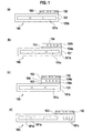
- Fig. 1(a) is a cross sectional drawing showing the formation of electrical wiring such as ground wiring, or power supply wiring or wiring for delivering electrical signals on the surface of an optical connecting member 100 that provides a function for passing light used for illumination.
- the part for delivering light used for illumination has the configuration of the optical waveguide 101 comprised of a core 101a through which light passes and cladding 101b covering the core.
- the electrical wiring part is configured having a flexible printed wiring substrate 102 adhered via an adhesive agent 103 to the surface of the optical waveguide 101 through which the illuminating light passes.
- Fig. 1b shows a configuration in which an optical waveguide 104 for delivering optical signals is adhered on the surface of an optical connecting member 100 that provides functionality for carrying light used for illumination.
- the optical waveguide 104 for carrying optical signals is comprised of a core 104a through which light passes and cladding 104b covering the core.
- Fig. 1(c) shows a configuration in which an optical electrical composite substrate providing both an optical waveguide 104 for carrying optical signals and electrical wiring 102 like a flexible printed wiring substrate having ground wires, power supply wires and signal wires for delivering electrical signals is adhered over the surface of an optical connecting member 100 providing functionality for carrying light used for illumination.
- Fig. 1(d) shows an example in which optical wiring for signal transmission and regions for guiding light used for illumination are formed arranged abreast inside the optical connecting member 100 used for illumination, and then a flexible printed wiring substrate 102 is applied thereover.
- the optical waveguide core 101c used for sending optical signals is formed arranged abreast with the optical waveguide core 101 a for illumination in the cladding 101b.
- the width of the illumination optical connecting core 101a and the width of the optical signal transmission core 101c may be the same or different, while the height of these also, may be the same or different.
- the size of the cores may be altered in accordance with the respective function.
- the display apparatus employing the optical connecting member related to the present invention realizes reduced power consumption and cost reductions.
- Fig. 2 is an external perspective view of a portable telephone that utilizes the present invention.
- This portable telephone device 1 is a folding type and provides a main body 4 further providing a surface 3 having a key operating part 2 that is the second lighting region.
- a closing lid part 6 is connected via a hinge part 5 so as to be able to open and close over the main body 4. That is to say, the main body 4 and closing lid part 6 are connected via the hinge part 5 so as to be able to rotate.
- the allowable angle of rotation may be within a range from 0-180°, or more preferably 0-360°.
- the surface 7 of the closing lid part 6 which forms the surface opposing the key operating part 2 is provided with a display part 8 that is the first lighting region.
- the display part 8 displays character or image information in response to operation of the key operating part 2 of the main body 4. For example, the display part 8 can display telephone numbers or previously taken images.
- the main body 4 has the key operating part 2comprised of a plurality of keys and a microphone 9 formed in the surface 3. Further, the main body 4 has housed internally, memory such as EEPROM or the like, a control part such as a CPU, and signal processing parts providing wireless functions and transmission functions or the like.
- a special characteristic of the main body 4 is the provision of the key operating part side, light guide plate that guides light emitted from a surface light source of the closing lid part 6 described subsequently, for illuminating the key operating part 2.
- the key operating part side, light guide plate can be simply of a light reflecting material such as silicon resin.
- the closing lid part 6 provides speakers 10.
- the display part 8 comprises a surface light source and a liquid crystal display part illuminated by the surface light source.
- the liquid crystal display part is provided with a surface light source within the closing lid part.
- the surface light source has a light source such as for example a white lighting LED and a display part side, light guide plate, that reflects or passes incoming light when light is input from this light source, to illuminate the liquid crystal display part.
- the surface light source and liquid crystal display part will be described in detail subsequently.
- a flexible optical waveguide is provided that flexibly connects the display part side, light guide plate and the key operating part side, light guide plate and operates as an optical connecting member guiding light emitted from the light source to the key operating part side, light guide plate.
- the flexible optical waveguide passes partly within the hinge part 5 that rotatably connects the main body 4 and the closing lid part 6.
- Fig. 3 is a side view of the display part 8 that is the first lighting region.
- the first lighting region has a light source and a light guide plate and for example may be configured as described above, such that the display part 8 has a plain light source 11 having a light source and a light guide plate and a liquid crystal display part 12 that is illuminated by the plain light source 11.
- the plain light source 11 is comprised for example of a white light LED 13 that emits light of wavelengths 420-750 nm, light guide plate of a display part side 14 which receives white light from the white light LED 13 via an end surface 14a, a reflecting plate 15 and a luminance enhancement sheet 16.
- the light guide plate of a display part side 14, the reflecting plate 15 and the luminance enhancement sheet 16 are stacked one on top of the other, comprising the plain light source 11.
- a diffusive film may be arranged between the light guide plate 14 and the luminance enhancement sheet 16.
- the luminance enhancement sheet 16 may use not one sheet but two sheets stacked.
- An example of the light source 13 could be a white light LED that emits visible light of wavelengths 380-780 nm.
- the light guide plate of a display part side 14 has the end surface 14a that is an end surface part into which light from the light source enters, the reflecting surface 14b that either reflects or passes incoming light entering via the end surface 14a, a first outgoing surface 14c that emits light input from the end surface 14a to the liquid crystal display part 12 side and a second outgoing surface 14d that emits the incoming light to the optical connecting member 17.
- the second outgoing surface 14d is disposed at the opposing side in relation to the end surface 14a.
- the reflecting plate 15 is disposed at the reflecting surface 14b side of the light guide plate 14, and reflects light passing the reflecting surface 14b returning it to the display part side, light guide plate.
- the reflecting plate 15 may be formed by using the vacuum evaporation method or sputter method to apply a glossy metallic thin film such as silver or aluminum or the like over the surface of a plastic film for example.
- the luminance enhancement sheet 16 is a film having a microprism, micro lens, diffraction lattice or hologram or the like, and functions to focus light emitted from the light guide plate of a display part side 14 in the direction of the liquid crystal cell 19.
- the liquid crystal display part 12 comprises a light polarizing plate 18 into which light passing via the focusing lens 16 enters and liquid crystal cell 19 into which light passing via the light polarizing plate 18 enters.
- the liquid crystal cell 19 is comprised of liquid crystals inserted between two transparent substrates.
- a diffusive film may be disposed between the focusing lens 16 and the light polarizing plate 18.
- Fig. 4 is a plan view of the display part side, light guide plate 14.
- the light guide plate of a display part side 14 has a substantially rectangular form, having a substantially rectangular shaped first outgoing surface 14c and reflecting surface 14d opposing the first outgoing surface 14c.
- the material from which the light guide plate of a display part side 14 is made should be a transparent material having a constant refractive index, such as for example polymethylmethacrylate, polyolefin or polycarbonate or the like, but these examples are illustrative and not restrictive, and any thermoresin, thermal hardened resin or optical hardened resin is satisfactory.
- the end surface 14a of the light guide plate 14 is substantially orthogonal to the first outgoing surface 14c and the reflecting surface 14b.
- the plurality of white light LED (light source) 13 are arranged linearly at substantially constant intervals opposing the end surface 14a. Light emitted from these light source 13 enters the light guide plate of a display part side 14 via the end surface 14a.
- the first outgoing surface 14c has a substantially planar form.
- the light guide plate 14b is substantially parallel to the first outgoing surface 14c of the light guide plate 14 and is formed having a plurality of reflecting grooves 20.
- These reflecting grooves 20 are formed in a direction substantially parallel or circular arc shaped in relation to the end surface 14a, and run continuously from the end surface 14a to the region at the end face of the opposite side of the end surface 14a.
- the cross-sectional form of these reflecting grooves 20 is asymmetrical, and the surfaces inclined toward the end surface 14a side have a wider width than the surfaces inclined toward the opposite side of the entry surface.
- the light guide plate of a key operating part side operates to guide light emitted from the second outgoing surface 14d of the light guide plate of a display part side 14 to illuminate the key operating part 2.
- the material for the light guide plate of a key operating part side should be a transparent material having a constant refractive index. This could be for example polymethylmethacrylate, polyolefin or polycarbonate or the like, but these examples are illustrative and not restrictive.
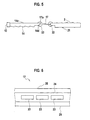
- Fig. 5 is a cross-sectional view showing the condition in which the light guide plate 14 of the first lighting region and the light guide plate of a key operating part side 21 of the second lighting region are connected by the optical connecting member 17.
- the optical connecting member 17 is a connecting member that flexibly connects the second outgoing surface 14d of the light guide plate 14 and the light guide plate of a key operating part side 21, and guides light from the light source 13 emitted via the second outgoing surface 14d to the light guide plate of a key operating part side 21.
- the optical connecting member 17 is highly refractive, heat resistant and transparent. It passes light of wavelengths 420-750 nm from the light source 13 and also, visible light of wavelengths 380-780 nm.
- the optical connecting member 17 is comprised of a transparent material that has the transmittance of light not less than 85% of light of wavelengths 420 nm-780 nm incoming from the light guide plate 14. Accordingly, if the light is of wavelengths 420 nm-780 nm, the second lighting region can utilize light from the light source of the first lighting region that passes due to this transmittance of light of not less than 85%.
- This kind of optical connecting member 17 can be constructed by arranging glass fibers, plastic fibers or resin tubes side-by-side, or by laying plastic fibers, glass fibers or resin tubes buried in resin. A concrete description of the configuration follows.
- the optical connecting member 17 should preferably be of a resinous composition or resinous material that passes not less than 85% of light of wavelength regions corresponding to the color of light illuminating the second lighting region.
- this resinous material has the transmittance of light not less than 85% in relation to light of wavelengths 420 nm-780 nm.
- the optical connecting member 17 should preferably be comprised of a resinous material, for example phenoxy resin, epoxy resin, (meta) acrylic resin, polycarbonate, polyarylate, polyamide, polyimide, or polyethersulfone, or a derivative of these.
- a resinous material for example phenoxy resin, epoxy resin, (meta) acrylic resin, polycarbonate, polyarylate, polyamide, polyimide, or polyethersulfone, or a derivative of these.
- phenoxy resin is the most suitable.
- epoxy resin especially epoxy resin hardened at room temperature (25°) is most preferable.
- phenoxy resin refers to acrylic resin or methacrylic resin.
- the material used could be polyester such as polyethylene terephthalate (PET), polybutylene terephthalate or polyethylene naphthalate or the like, polyolefin such as polyethylene or polypropylene or the like, an alicyclic polyolefin such as Arton (registered trademark of JSR Corporation), polycarbonate, polyamide, polyimide, polyamidomide, polyetherimide, polyethersulfide, polyethersulfone, polyarylate, liquid crystal polymer, polysulfone or silicon resin.
- PET polyethylene terephthalate
- polybutylene terephthalate or polyethylene naphthalate or the like polyolefin such as polyethylene or polypropylene or the like
- an alicyclic polyolefin such as Arton (registered trademark of JSR Corporation)
- polycarbonate polyamide, polyimide, polyamidomide, polyetherimide, polyethersulfide, polyethersulfone, polyarylate, liquid crystal polymer
- the optical connecting member 17 may be a resinous composition including at least one from among (A) binder polymer, (B) photopolymer compound or (C) photopolymer initiator. Additionally, the optical connecting member 17 may, as necessary, include at least one additive from among an antioxidant, an anti-yellowing agent, a UV light absorbent, a visible light absorbent, a coloring agent, a plasticizer, a stabilizing agent, a filler or a transmissive spectrum control agent.
- Fig. 5 shows the configuration in which the optical connecting member 17 and the display part side, light guide plate 14 of the first lighting region, and the optical connecting member 17 and the key operating part side, light guide plate 21 of the second lighting region are connected by an adhesive agent 22 comprised of resin.
- the optical connecting member 17 guides the light entering from the entry surface 17a to illuminate the key operating part 2.
- the portable telephone 1 simultaneous with using light from the light source 13 to illuminate the liquid crystal display part 12, can use the same light from the light source 13 to illuminate the cladding layer 24.
- the optical connecting member 17 in the portable telephone 1 guides light from the light source of the first lighting region via a light guide plate to the second lighting region, thus the second lighting region does not require an independent light source, accordingly, the portable telephone 1 realizes reduced power consumption and cost reductions.
- Fig. 6 is a cross-sectional view of the optical connecting member 17.
- the optical connecting member 17 is a flexible optical waveguide that comprises a core 23 comprised of resin forming a core layer that has a high refractive index and a cladding layer 24 comprised of resin used for forming cladding that has a low refractive index.
- the cladding layer is protected by a cover film 25.
- the core 23 is formed by irradiating the core layer comprised of core layer forming resin via a negative mask pattern with excited light rays irradiated in image form, then applying developing processes to form a pattern.
- the cover film 25 can be arranged on either side of the cladding layer 24. By applying the cover film 25 the flexibility and toughness of the cover film 25 is added to the optical connecting member 17. Further, as the optical waveguide is less susceptible to soiling and damage it becomes easier to handle.
- Fig. 7 shows the process for producing a flexible optical waveguide.
- the cladding is formed of a lower cladding 24d and an upper cladding 24u.
- the lower cladding 24d is formed over the substrate 25 by a laminating/hardening (exposure and thermal application) process.
- the core film is laminated, forming the core layer 23.
- the core layer is exposed to light via a core pattern mask.
- the core 23 is formed when the development process is applied at step (d).
- the upper cladding 24u is laminated with film and hardened so as to cover the core 23 thereby completing the optical connecting member 17.
- the cladding layer which should have a lower refractive index than the core layer, it is suitable to use a photosensitive resinous composition or thermal hardenable resinous composition hardened either optically or thermally.
- the core layer which should have a higher refractive index than the cladding layer, it is suitable to use a photosensitive resinous composition that can sustain formation of a core pattern through irradiation of an excited light source such as ultraviolet rays or the like.
- Fig. 8 shows the configuration in which the light guide plate 14 of the first lighting region and the optical connecting member 17, and the optical connecting member 17 and the key operating part side, light guide plate 21 of the second lighting region are connected either by a film shaped sticky sheet 28 or sticky tape 28.
- Fig. 9 shows the configuration in which the light guide plate 14 of the first lighting region and an optical connecting member comprised of the core 23 and the cladding layer 24, and the optical connecting member comprised of the core 23 and the cladding layer 24 and the key operating part side, light guide plate 21 of the second lighting region are connected via the adhesive agent 22 comprised of resin, or the film shaped, sticky sheet 28, or the sticky tape 28.
- Fig. 10 shows the configuration in which the light guide plate 14 of the first lighting region and the optical connecting member 17, and the optical connecting member 17 and the key operating part side, light guide plate 21 of the second lighting region are connected by being laminated by the cladding 24, formed so as to cover both above and below the core 23 of the optical connecting member.
- Fig. 11 shows the configuration in which the light guide plate 14 of the first lighting region and the optical connecting member 17, and the optical connecting member 17 and the key operating part side, light guide plate 21 of the second lighting region are formed as an integrated body by a transparent material with a constant refractive index used for the light guide plate. That is to say, the light guide plate 14, the key operating part side, light guide plate 21 and the optical connecting member 17 are formed into an integrated body by the same flexible resinous material.
- the light guide plate 14 of the first lighting region and the optical connecting member 17, and the optical connecting member 17 and the key operating part side, light guide plate 21 of the second lighting region can be mechanically interlock connected using a connector part.
- the light guide plate 14 of the first lighting region (display 8) and the optical connecting member 17, and the optical connecting member 17 and the key operating part side, light guide plate 21 of the second lighting region (key operating part 2) can be connected each overlapping one on another.
- Fig. 12(a) shows the specific example in which the extending part 14e of the reflecting surface 14b of the light guide plate 14 overlaps in connection with a part 17a of the upper surface of one end of the optical connecting member 17.
- the other end part 17c of the optical connecting member 17 connects with the end part 21a being the other end of the key operating part side, light guide plate 21.
- Fig. 12(b) shows the example in which the extending part 14f of the first outgoing surface 14c of the light guide plate 14 overlaps in connection with a part 17b of the lower surface of one end of the optical connecting member 17.
- the end part 17c being the other end of the optical connecting member 17 connects with the end part 21a at the other end of the key operating part side, light guide plate 21.
- Fig. 12(c) shows the example in which the extending part 14e of the reflecting surface 14b of the light guide plate 14 overlaps in connection with the part 17a of the upper surface of one end of the optical connecting member 17 via the adhesive agent 22.
- the end part 17c being the other end of the optical connecting member 17 connects with the end part 21a at the other end of the key operating part side, light guide plate 21.
- the optical connecting member 17 is connected at the reflecting surface 14b side of the light guide plate 14, however it may be connected at the first outgoing surface 14c side of the light guide plate 14.
- Fig. 12(d) shows the example in which the extending part 14e of the reflecting surface 14b of the light guide plate 14 overlaps in connection with the part 17a of the upper surface of one end of the optical connecting member 17, moreover the part 17d of the upper surface at the other end of the optical connecting member 17 connects to the upper surface 21b of the other end of the key operating part side, light guide plate 21.
- the optical connecting member 17 is connected at the reflecting surface 14b side of the light guide plate 14, however it may be connected at the first outgoing surface 14c side of the light guide plate 14 and it may be connected using an adhesive agent.
- the optical connecting member 17 is connected to the lower surface 21b of the key operating part side, light guide plate 21 however it may also be connected to the upper surface, and may be connected using an adhesive agent.
- the optical connecting member 17 described above must of course be flexible, but must have folding endurance and elasticity.
- the rate of increase of optical insertion loss in the 360° bending test with radius of curvature 2 mm is not more than 1 dB; that the rate of increase of optical insertion loss after the repetitive bending test with radius of curvature 5 mm is repeated 100,000 times is not more than 1 dB; and that mechanical damage such as cracks does not occur in the core after the repetitive bending test with radius of curvature 2 mm is repeated 100,000 times.
- the existence of such mechanical damage such as cracks can be confirmed under a magnifying lens, under a microscope or with the naked eye.
- the coefficient of elasticity using a film tensile test is 0.05-6 GPa.
- optical transmission loss of the optical connecting member 17 in the 450-750 nm wavelength regions should be not more than 3 dB/cm.
- the optical connecting member 17 has a core part and a cladding part the refractive index of which is lower than that of the core part, and the relative refractive index difference of the cladding part and the core part of the optical connecting member is 1-50%. This value applies to the case in which the optical connecting member comprises only the core part and the cladding part is air.
- the thickness of the end surface opposing the first lighting region of the optical connecting member is 0.01-2 mm.
- optical connecting member 17 in addition to the optical connecting member 17, it is possible to employ a member used for another purpose, that is flexible like the optical connecting member 17.
- a member used for another purpose that is flexible like the optical connecting member 17.
- a configuration in which a circuit substrate used as a medium for conveying light as electrical signals is integrated either by pressure or connection to the optical connecting member 17 is feasible.
- the second lighting region illuminates each key of the key operating part through the operation of the light guide plate.
- Fig. 13 is a cross-sectional view of the region of the key 2a region of the key operating part 2.
- Fig. 13(a) is an example showing a cross-sectional view of the position of the key 2a of the key operating part 2.
- the key 2a is arranged over the switching elements 68 disposed on a substrate 67, via a light guide plate 21.
- a convex part 2b is disposed at the lower side of the key 2a.
- the convex part 2b pressures the switching elements 68 over the substrate 67 via the flexible light guide plate 21, to complete the switching action.
- Reflective elements 21 a that diffract light entering the light guide plate of a key operating part side 21 via the optical connecting member 17 at substantially 90°, thereby projecting the light to the lower surface of the key 2a, are formed in a region substantially relative to the key 2a on the light guide plate of a key operating part side 21.
- the reflective elements 21a can be provided by using reflective elements used for commonly known light guide plates providing the backlights for ordinary liquid crystal display apparatus such as those providing a fine prism form or dot form or the like. Further, in Fig. 13(a) , the reflective elements 21a are formed at the side in contact with the key 2a of the light guide plate 21, however these elements can also be formed at the opposite side having the switch elements 68.
- Fig. 13(b) is another example showing a cross-sectional view of the position of the key 2a of the key operating part 2.
- openings 21b are positioned in locations corresponding to the key 2a of the light guide plate of a key operating part side 21, and the convex part 2b of the lower surface of the key 2a directly pushes the switching elements 68.
- Light entering the light guide plate of a key operating part side 21 via the optical connecting member 17 is reflected at the side faces of the openings 21b and projected to the lower surface of the key 2a.
- Tapers are formed for the side surfaces of the openings 21b to facilitate projection to the lower surface of the key 2a.
- the substrate 67 and the switching elements 68 can be covered with a flexible, thin sheet.
- a white colored sheet is preferable in order to more brightly project light to the lower surface of the key 2a.
- illumination to both the first lighting region and the second lighting region goes off if a certain time has elapsed without activity, and returns when some action, such as pushing a key switch or the like, is performed.
- illumination to the first lighting region when illumination to the first lighting region is on, illumination to the second lighting region also, goes to on.
- Fig. 14 is an external perspective view showing a personal computer 31 to which the present invention can be applied.
- This personal computer 31 is a folding shut type, comprising a main body 34 which further provides a key operating part 32 and a surface 33, and a closing lid 36 connected to the main body 34 via a hinge 35 that enables the closing lid 36 to open and close. That is to say, the main body 34 and closing lid 36 are connected so as to be able to rotate, via the hinge 35.
- a display part 38 is provided in the surface 37 which forms the surface opposing the key operating part 32. This display part 38 displays image or character information based on the operations performed using the key operating part 32 of the main body 34.
- the main body 34 provides the key operating part 32 itself comprised of a plurality of keys, formed in the surface 33. Further, the main body 34 houses internally memory such as EEPROM or the like, a control part such as a CPU, and signal processing parts providing wireless functions and transmission functions or the like.
- a special characteristic of the main body 34 is the provision of the key operating part side, light guide plate that guides light emitted from a surface light source of the closing lid 33 for illuminating the key operating part 32.
- the closing lid 36 provides the display part 38 in the surface 37.
- the display part 38 comprises a surface light source and a liquid crystal display part illuminated by the surface light source.
- the liquid crystal display part is provided with a surface light source within the closing lid part.
- the surface light source has a light source such as for example a white lighting LED and a display part side, light guide plate, that reflects or passes incoming light when light is input from this light source, to illuminate the liquid crystal display part.
- an optical connecting member is provided that flexibly connects the display part side, light guide plate and the key operating part side, light guide plate and operates as a connecting member guiding light emitted from the light source to the key operating part side, light guide plate.
- the optical connecting member passes partly within the hinge 35 that rotatably connects the main body 34 and the closing lid 36.
- the display part side, light guide plate, the key operating part side, light guide plate at the optical connecting member are as described with reference to Figs. 3 through 13 .
- the personal computer 31 realizes low power consumption and cost reductions.
- the display apparatus could include for example, that of a foldable portable telephone, a portable telephone device such as a twin screen portable telephone or the like, a personal computer, a twin screen portable game machine or an electronic dictionary with screen for handwritten input.
- Fig. 15 is an external perspective view of a twin screen, foldable portable telephone 41.
- the first display part (liquid crystal display) 43 provided in the main body 42 forms the second lighting region
- the second display part (liquid crystal display) 45 provided in the closing lid 44 forms the first lighting region.
- a microphone 46 or the like, is installed in the closing lid 42.
- the first display part 43 forms a touch panel.
- the touch panel can display a plurality of different kinds of icons in the screen. Weather information can also be displayed.
- Fig. 16 is an external perspective view of a twin screen, portable game machine 51.
- the first display part (liquid crystal display) 53 provided in the main body 52 forms the second lighting region, while the second display part (liquid crystal display) 55 provided in the closing lid 54 forms the first lighting region.
- a key operating part 56 is installed in the main body 52.
- the first display part 53 forms a touch panel. The touch panel is operated as the user directly touches the screen.
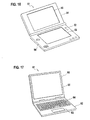
- Fig. 17 is an external perspective view of an electronic dictionary 61 with screen for handwritten input.
- a handwritten input screen (touch panel) 63 and key operating board 64 are provided in the main body 62. These handwritten input screen 63 and the operating part 64 are equivalent to the second lighting region.
Landscapes
- Physics & Mathematics (AREA)
- General Physics & Mathematics (AREA)
- Optics & Photonics (AREA)
- Engineering & Computer Science (AREA)
- Signal Processing (AREA)
- Planar Illumination Modules (AREA)
- Light Guides In General And Applications Therefor (AREA)
- Telephone Set Structure (AREA)
Abstract
Description
- The present invention relates to an optical connecting member that connects two lighting regions and a display apparatus that utilizes this optical connecting member.
- Information processing devices such as portable telephones or personal digital assistants (PDA) as well as laptop computers and the like always provide illumination for a liquid crystal display that displays images and characters, and now it is common for these types of devices to provide illumination of the parts of the device for operating the keys as well.
- For example, as disclosed in the following
Patent Document 1, in the portable telephone device both the display part and the key operating part are each provided with a dedicated light source. The liquid crystal display part is lighted by a backlight utilizing a light guide plate, while the key operating part is illuminated by an LED or the like attached to a substrate. - [Patent Document 1] Japanese Patent Application Laid-Open No.
2004-295187 - [Patent Document 2] Patent publication No.
2004-508599 - In the portable telephone device with lighting function provided disclosed in
Patent Document 1, above, dedicated light sources are provided for each of the liquid crystal display and the keyboard operating parts, meaning that power consumption is substantial and the battery will be quickly exhausted. Further, usually a plurality of keys are provided in a key operating part which raises concerns that having to provide light source to each individual key mitigates against cost reductions. - Against this background, the present invention aims to provide a display apparatus and an optical connecting member in which there is reduced power consumption by an information processing device provided with lighting functionality, and that furthermore enables cost reductions.
- With the foregoing problems in view, the optical connecting member according to the present invention is configured such that between a first lighting region having a light source and a light guide plate, and a second lighting region, light emitted from an end surface of the light guide plate is guided to the second lighting region. Because the optical connecting member operates to guide light, via the light guide plate, from the light source of the first lighting region to the second lighting region an independent light source is not required for the second lighting region.
- It is preferable in this optical connecting member, that the transmittance of light of a wavelength region corresponding to the color illuminating the second lighting region is not less than 85%. It is preferable, especially when the second lighting region is illuminated with white light, that the optical connecting member is of a transparent material such that the transmittance of light in the wavelength region from 420 nm - 780 nm is not less than 85%. Where this condition is fulfilled, if light is in the wavelength region of 420 nm-780 nm, the second lighting region can utilize the light that passes with the transmittance of light not less than 85% from the light source of the first lighting region.
- Further, it is preferable in the optical connecting member, that the rate of increase of loss in the 360° bending test with radius of
curvature 2 mm is not more than 1 dB. That is to say, even where there are strict usage conditions such that there is 360° bending for radius ofcurvature 2 mm, the optical connecting member minimizes light loss. - Again, it is preferable in the optical connecting member, that the rate of increase of optical insertion loss after the repetitive bending test with radius of
curvature 5 mm is repeated 100,000 times is not more than 1 dB. Bending at a radius ofcurvature 5 mm repeated 100 times each day and further continuing this over three years results in testing 100,000 times. Even under these conditions of usage, the increase of optical insertion loss is not more than 1 dB. - Further, it is preferable in the optical connecting member, that mechanical damage such as cracks dose not occur in the core after the repetitive bending test with radius of
curvature 2 mm is repeated 100,000 times. The existence of such mechanical damage such as cracks can be confirmed under a magnifying lens, under a microscope or with the naked eye. - Moreover, it is preferable in the optical connecting number, that the coefficient of elasticity using a film tensile test is 0.05-6 GPa.
- Again, it is preferable that the optical connecting member has a core part and a cladding part the refractive index of which is lower than that of the core part. Thus, light travels in the core part which has a higher refractive index.
- Further, it is preferable that the relative refractive index difference of the cladding part and the core part of the optical connecting member is 1-50%. Here, this includes cases in which the optical connecting member comprises only the core part and the cladding part is air.
- Moreover, it is preferable that the thickness of the end surface opposing the light guide plate of the first lighting region of the optical connecting member is 0.01-2 mm.
- Again, it is preferable in the optical connecting member that the exterior of the cladding part has a supporting film.
- Further, the optical connecting member may use an optical waveguide having a core part and cladding part.
- Moreover, the optical connecting member may employ a configuration of glass fiber, plastic fiber or resin tubes arranged in parallel.
- Again, the optical connecting member may employ a configuration of glass fiber, plastic fiber or resin tubes laid inside resin.
- In order to solve the above described problems, the display apparatus according to the present invention provides any of the optical connecting members as described above, as well as a first lighting region and a second lighting region, the first lighting region has a light source and a light guide plate, and the optical connecting member guides light emitted from the end surface of the light guide plate to the second lighting region. The optical connecting member of the display apparatus guides light from the light source of the first lighting region to the second lighting region via a light guide plate, thus the display apparatus does not require an independent light source in the second lighting region.
- In this display apparatus, the first lighting region and the optical connecting member, and the optical connecting member and the second lighting region are connected by an adhesive agent comprised of resin.
- Again, in the display apparatus the first lighting region and the optical connecting member, and the optical connecting member and the second lighting region are connected by a film shaped sticky resinous sheet or by a resinous tape.
- Further, the first lighting region and the optical connecting member, and the optical connecting member and the second lighting region are connected by a film shaped sticky resinous sheet or by a resinous tape, moreover, these may be connected by an adhesive agent comprised of resin.
- Moreover, in the display apparatus, the optical connecting member has a core part and cladding part, and the first lighting region and the optical connecting member, as well as the optical connecting member and the second lighting region, are connected by being laminated by a cladding layer formed so as to cover both above and below the core part of the optical connecting member.
- Again, the first lighting region and the optical connecting member, and the optical connecting member and the second lighting region may be mechanically joined using a connector part.
- Further, the second lighting region has a light guide plate, and the light guide plate of the first lighting region as well as the optical connecting member and the light guide plate of the second lighting region are formed into an integrated body by the same flexible, resinous material.
- Moreover, it is preferable that the first lighting region is provided with a closing lid part, that the second lighting region is provided with a main body, and that the optical connecting member and the closing lid part and the main body are rotatably connected via a hinge part. Here, "rotatably connected" means connected so as to be able to fold and mechanistically turn, rotating at a point. If at least one of the folding action or the turning rotating action is possible, it can be said to be rotatable.
- Again, it is preferable that a movable part is provided for a configuration that connects the first lighting region to the closing lid part, the second lighting region to the main body, and the optical connecting member slides with the closing lid part and the main body part.
- The display apparatus according to the present invention could include for example, that of a foldable portable telephone, a portable telephone device such as a twin screen portable telephone or the like, a personal computer, a twin screen portable game machine or an electronic dictionary with screen for handwritten input.
- That is to say, the display apparatus comprises a first lighting region providing a surface light source part having a light source and a light guide plate, and a liquid crystal display part that is illuminated by the surface light source, which first lighting region reflects or passes light from the light source, emits light from a first outgoing edge opposing the liquid crystal display part to illuminate the liquid crystal display part, and also emits light from a second end surface opposing the optical connecting member; the optical connecting member that flexibly connects the first lighting region and the second lighting region positioned between them, and guides the light emitted from the second end surface of the first lighting region to the second lighting region; and a second lighting region having a key operating part connected to the first lighting region via the optical connecting member so as to be able to open and close: such that the display apparatus could for example function as an information processing device with lighting functionality, that displays image information or character information on the liquid crystal display part based on operations performed using the operating part
- It is preferable that the optical connecting member be of a resinous material. It is preferable that this resinous material be for example phenoxy resin, epoxy resin, (meta) acrylic resin, polycarbonate, polyarylate, polyetheramide, polyetherimide or polyethersulfone, or again, a derivative of at least one of these.
- Among these resinous materials it is preferable, considering heat resistance properties, that the material has an aromatic ring in the principal chain, so phenoxy resin is the most suitable. Again, considering three-dimensional linkage and even greater heat resistance properties, epoxy resin, especially epoxy resin hardened at room temperature (25°) is most preferable. Considering transmissive ability the most preferred materials are phenoxy resin and (meta) acrylic resin. Here, (meta) acrylic resin refers to acrylic resin or methacrylic resin.
- It is preferable, considering the properties of flexibility, toughness and transmissive ability to use a polyester such as polyethylene terephthalate (PET), polybutylene terephthalate or polyethylene naphthalate or the like, polyolefin such as polyethylene or polypropylene or the like, an alicyclic polyolefm such as Arton (registered trademark of JSR Corporation), polycarbonate, polyamide, polyimide, polyamidomide, polyetherimide, polyethersulfide, polyethersulfone, polyarylate, liquid crystal polymer, polysulfone or silicon resin.
- Again, the optical connecting member may be a resinous composition including at least one from among (A) binder polymer, (B) photopolymer compound or (C) photopolymer initiator.
- It is preferable that the optical connecting member be comprised of a resinous material or resinous composition that has the transmittance of light not less than 85% of light in wavelength regions corresponding to the color of illumination of the second lighting region. Especially when white light is illuminated in the second lighting region it is preferable that the transmittance of light of a light transmissive material is not less than 85% of light of wavelengths from 420 nm-780 nm.
- Further, the optical connecting member may include at least one additive from among an antioxidant, an anti-yellowing agent, a UV light absorbent, a visible light absorbent, a coloring agent, a plasticizer, a stabilizing agent or a filler.
- Moreover, the optical connecting member may have added therein a transmissive spectrum control agent such as a coloring agent or a fluorescent substance in order to control the transmission spectrum in coordination with the color illuminating the second lighting region.
- Again, the optical connecting member according to the present invention not only guides light emitted from the end surface of the light guide plate of the first lighting region, providing light used for illuminating the second lighting region which may be a key operating part or the like, it also provides a function of delivering an analogue or digital signal of electricity or light, and integrates the power supply wiring and ground wiring.
- For example, electrical wiring such as signal carrying wires for carrying electric signals, or power supply wires as well as ground wires or the like can be formed on the surface of an optical connecting member providing functionality for passing light used for illumination. The method for producing such electrical wiring can be for example: a method of adhering a flexible printed wiring substrate to the surface of such an optical connecting member used for illuminating using an adhesive agent; a method of directly forming electrical wiring on the surface of such an optical connecting member used for illuminating; a method of forming an optical waveguide as an optical connecting member used for illuminating that involves a buildup approach, first forming over a flexible printed wiring substrate a core pattern consisting of a consecutive arrangement having ground layers underneath followed by core layers over the ground layers, then forming an upper cladding layer; or a method of forming an optical connecting member used for illuminating such as an optical waveguide or the like over a film with metallic foil attached, then patterning the electrical wiring on the metal.
- Moreover, in addition to directing light used for illumination, optical signal transmission regions can be formed on the optical connecting member used for illumination, to enable digital or analog signals to be sent as light, thus for example, a flexible optical waveguide can be formed on the surface of the optical connecting member used for illumination, or optical wiring for signal transmission and regions for guiding light used for illumination can be formed arranged abreast inside the optical connecting member used for illumination. Further, both transmission paths for sending electrical signals and transmission paths for sending optical signals can be formed on the optical connecting member used for illumination.
- A single example will now be described with reference to
Fig. 1(a). Fig. 1(a) is a cross sectional drawing showing the formation of electrical wiring such as ground wiring, or power supply wiring or wiring for delivering electrical signals on the surface of an optical connectingmember 100 that provides a function for passing light used for illumination. The part for delivering light used for illumination has the configuration of theoptical waveguide 101 comprised of acore 101a through which light passes andcladding 101b covering the core. InFig. 1(a) the electrical wiring part is configured having a flexible printedwiring substrate 102 adhered via anadhesive agent 103 to the surface of theoptical waveguide 101 through which the illuminating light passes. -
Fig. 1b shows a configuration in which anoptical waveguide 104 for delivering optical signals is adhered on the surface of an optical connectingmember 100 that provides functionality for carrying light used for illumination. Theoptical waveguide 104 for carrying optical signals is comprised of acore 104a through which light passes andcladding 104b covering the core. -
Fig. 1(c) shows a configuration in which an optical electrical composite substrate providing both anoptical waveguide 104 for carrying optical signals andelectrical wiring 102 like a flexible printed wiring substrate having ground wires, power supply wires and signal wires for delivering electrical signals is adhered over the surface of an optical connectingmember 100 providing functionality for carrying light used for illumination. - It is also suitable, that instead of adhering an optical waveguide to the surface of the optical connecting member used for illumination using an adhesive agent, there is a buildup over the surface of the optical connecting member to form an optical waveguide for optical signal transmission, realized by first forming over the surface of the optical connecting member a core pattern consisting of a consecutive arrangement having ground layers underneath followed by core layers over the ground layers, and then adhering a flexible printed wiring substrate over the optical waveguide using an adhesive agent. Further, it is possible to form a consecutive buildup of optical waveguides for optical transmission and optical waveguides for illumination over a film with metallic foil attached then patterning the electrical wiring on the metal.
-
Fig. 1(d) shows an example in which optical wiring for signal transmission and regions for guiding light used for illumination are formed arranged abreast inside the optical connectingmember 100 used for illumination, and then a flexible printedwiring substrate 102 is applied thereover. Theoptical waveguide core 101c used for sending optical signals is formed arranged abreast with theoptical waveguide core 101 a for illumination in thecladding 101b. - Here, the width of the illumination optical connecting
core 101a and the width of the opticalsignal transmission core 101c may be the same or different, while the height of these also, may be the same or different. The size of the cores may be altered in accordance with the respective function. - The display apparatus employing the optical connecting member related to the present invention realizes reduced power consumption and cost reductions.
-
-
Fig. 1 shows a cross-section of an optical connecting member; -
Fig. 2 is an external perspective view of a portable telephone that utilizes the present invention; -
Fig. 3 is a side view of the display part shown inFig. 2 ; -
Fig. 4 is a plan view of the display part side, light guide plate shown inFig. 3 ; -
Fig. 5 is a side view showing the condition in which the display part side, light guide plate and key operating part side, light guide plate are connected via an optical connecting member; -
Fig. 6 is a cross-sectional view of the optical connecting member; -
Fig. 7 shows the process for producing the flexible optical connecting member; -
Fig. 8 shows a first specific example in which the first lighting region and the second lighting region are connected via the optical connecting member; -
Fig. 9 shows a second specific example in which the first lighting region and the second lighting region are connected via the optical connecting member; -
Fig. 10 shows a third specific example in which the first lighting region and the second lighting region are connected via the optical connecting member; -
Fig. 11 shows a fourth specific example in which the first lighting region and the second lighting region are connected via the optical connecting member; -
Fig. 12 shows a fifth specific example in which the first lighting region and the second lighting region are connected via the optical connecting member; -
Fig. 13 Fig. 13(a) and 13b are cross-sectional views of the area in which the keys are located in the key operating part, andFig. 13(c) shows the light guide plate for the case shown inFig. 13b ; -
Fig. 14 is an external perspective view of a personal computer suited to application of the present invention; -
Fig. 15 is an external perspective view of a twin screen portable telephone suited to application of the present invention; -
Fig. 16 is an external perspective view of a twin screen portable game machine suited to application of the present invention; and -
Fig. 17 is an external perspective view of a handwritten input screen electronic dictionary suited to application of the present invention. -
- 1
- Portable telephone
- 2
- Key operating part
- 3
- Surface
- 4
- Main body
- 5
- Hinge part
- 6
- Closing lid part
- 8
- Display part
- The best modes for carrying out the invention will now be described with reference to the drawings.
-
Fig. 2 is an external perspective view of a portable telephone that utilizes the present invention. Thisportable telephone device 1 is a folding type and provides a main body 4 further providing asurface 3 having akey operating part 2 that is the second lighting region. A closinglid part 6 is connected via ahinge part 5 so as to be able to open and close over the main body 4. That is to say, the main body 4 and closinglid part 6 are connected via thehinge part 5 so as to be able to rotate. The allowable angle of rotation may be within a range from 0-180°, or more preferably 0-360°. Thesurface 7 of the closinglid part 6 which forms the surface opposing thekey operating part 2 is provided with adisplay part 8 that is the first lighting region. Thedisplay part 8 displays character or image information in response to operation of thekey operating part 2 of the main body 4. For example, thedisplay part 8 can display telephone numbers or previously taken images. - The main body 4 has the key operating part 2comprised of a plurality of keys and a
microphone 9 formed in thesurface 3. Further, the main body 4 has housed internally, memory such as EEPROM or the like, a control part such as a CPU, and signal processing parts providing wireless functions and transmission functions or the like. A special characteristic of the main body 4 is the provision of the key operating part side, light guide plate that guides light emitted from a surface light source of the closinglid part 6 described subsequently, for illuminating thekey operating part 2. The key operating part side, light guide plate can be simply of a light reflecting material such as silicon resin. - In addition to the
display part 8 on thesurface 7 side, the closinglid part 6 providesspeakers 10. Thedisplay part 8 comprises a surface light source and a liquid crystal display part illuminated by the surface light source. The liquid crystal display part is provided with a surface light source within the closing lid part. The surface light source has a light source such as for example a white lighting LED and a display part side, light guide plate, that reflects or passes incoming light when light is input from this light source, to illuminate the liquid crystal display part. The surface light source and liquid crystal display part will be described in detail subsequently. - Moreover, between the main body 4 and the closing lid part 6 a flexible optical waveguide is provided that flexibly connects the display part side, light guide plate and the key operating part side, light guide plate and operates as an optical connecting member guiding light emitted from the light source to the key operating part side, light guide plate. The flexible optical waveguide passes partly within the
hinge part 5 that rotatably connects the main body 4 and the closinglid part 6. -
Fig. 3 is a side view of thedisplay part 8 that is the first lighting region. The first lighting region has a light source and a light guide plate and for example may be configured as described above, such that thedisplay part 8 has a plainlight source 11 having a light source and a light guide plate and a liquidcrystal display part 12 that is illuminated by the plainlight source 11. The plainlight source 11 is comprised for example of awhite light LED 13 that emits light of wavelengths 420-750 nm, light guide plate of adisplay part side 14 which receives white light from thewhite light LED 13 via anend surface 14a, a reflectingplate 15 and aluminance enhancement sheet 16. The light guide plate of adisplay part side 14, the reflectingplate 15 and theluminance enhancement sheet 16 are stacked one on top of the other, comprising the plainlight source 11. A diffusive film may be arranged between thelight guide plate 14 and theluminance enhancement sheet 16. Further, theluminance enhancement sheet 16 may use not one sheet but two sheets stacked. An example of thelight source 13 could be a white light LED that emits visible light of wavelengths 380-780 nm. - The light guide plate of a
display part side 14 has theend surface 14a that is an end surface part into which light from the light source enters, the reflectingsurface 14b that either reflects or passes incoming light entering via theend surface 14a, a firstoutgoing surface 14c that emits light input from theend surface 14a to the liquidcrystal display part 12 side and a secondoutgoing surface 14d that emits the incoming light to the optical connectingmember 17. The secondoutgoing surface 14d is disposed at the opposing side in relation to theend surface 14a. - The reflecting
plate 15 is disposed at the reflectingsurface 14b side of thelight guide plate 14, and reflects light passing the reflectingsurface 14b returning it to the display part side, light guide plate. The reflectingplate 15 may be formed by using the vacuum evaporation method or sputter method to apply a glossy metallic thin film such as silver or aluminum or the like over the surface of a plastic film for example. - The
luminance enhancement sheet 16 is a film having a microprism, micro lens, diffraction lattice or hologram or the like, and functions to focus light emitted from the light guide plate of adisplay part side 14 in the direction of theliquid crystal cell 19. - The liquid
crystal display part 12 comprises a lightpolarizing plate 18 into which light passing via the focusinglens 16 enters andliquid crystal cell 19 into which light passing via thelight polarizing plate 18 enters. Theliquid crystal cell 19 is comprised of liquid crystals inserted between two transparent substrates. A diffusive film may be disposed between the focusinglens 16 and thelight polarizing plate 18. -
Fig. 4 is a plan view of the display part side,light guide plate 14. The light guide plate of adisplay part side 14 has a substantially rectangular form, having a substantially rectangular shaped firstoutgoing surface 14c and reflectingsurface 14d opposing the firstoutgoing surface 14c. The material from which the light guide plate of adisplay part side 14 is made should be a transparent material having a constant refractive index, such as for example polymethylmethacrylate, polyolefin or polycarbonate or the like, but these examples are illustrative and not restrictive, and any thermoresin, thermal hardened resin or optical hardened resin is satisfactory. - The
end surface 14a of thelight guide plate 14 is substantially orthogonal to the firstoutgoing surface 14c and the reflectingsurface 14b. The plurality of white light LED (light source) 13 are arranged linearly at substantially constant intervals opposing theend surface 14a. Light emitted from theselight source 13 enters the light guide plate of adisplay part side 14 via theend surface 14a. The firstoutgoing surface 14c has a substantially planar form. - The
light guide plate 14b is substantially parallel to the firstoutgoing surface 14c of thelight guide plate 14 and is formed having a plurality of reflectinggrooves 20. These reflectinggrooves 20 are formed in a direction substantially parallel or circular arc shaped in relation to theend surface 14a, and run continuously from theend surface 14a to the region at the end face of the opposite side of theend surface 14a. The cross-sectional form of these reflectinggrooves 20 is asymmetrical, and the surfaces inclined toward theend surface 14a side have a wider width than the surfaces inclined toward the opposite side of the entry surface. Instead of the reflectinggrooves 20, it is also suitable to have dot patterns formed on the reflectingsurface 14b. These dot patterns can be of a printed reflective material or an imprinting concave convex form. The size, arrangement and concave-convex form of the dot patterns should be determined to enable uniform emission of light from the reflectingsurface 14b. - The light guide plate of a key operating part side will now be described. The light guide plate of a key operating part side operates to guide light emitted from the second
outgoing surface 14d of the light guide plate of adisplay part side 14 to illuminate thekey operating part 2. In the same manner as applies with respect to the light guide plate of adisplay part side 14, the material for the light guide plate of a key operating part side should be a transparent material having a constant refractive index. This could be for example polymethylmethacrylate, polyolefin or polycarbonate or the like, but these examples are illustrative and not restrictive. -
Fig. 5 is a cross-sectional view showing the condition in which thelight guide plate 14 of the first lighting region and the light guide plate of a keyoperating part side 21 of the second lighting region are connected by the optical connectingmember 17. The optical connectingmember 17 is a connecting member that flexibly connects the secondoutgoing surface 14d of thelight guide plate 14 and the light guide plate of a keyoperating part side 21, and guides light from thelight source 13 emitted via the secondoutgoing surface 14d to the light guide plate of a keyoperating part side 21. The optical connectingmember 17 is highly refractive, heat resistant and transparent. It passes light of wavelengths 420-750 nm from thelight source 13 and also, visible light of wavelengths 380-780 nm. The optical connectingmember 17 is comprised of a transparent material that has the transmittance of light not less than 85% of light of wavelengths 420 nm-780 nm incoming from thelight guide plate 14. Accordingly, if the light is of wavelengths 420 nm-780 nm, the second lighting region can utilize light from the light source of the first lighting region that passes due to this transmittance of light of not less than 85%. - This kind of optical connecting
member 17 can be constructed by arranging glass fibers, plastic fibers or resin tubes side-by-side, or by laying plastic fibers, glass fibers or resin tubes buried in resin. A concrete description of the configuration follows. - The optical connecting
member 17 should preferably be of a resinous composition or resinous material that passes not less than 85% of light of wavelength regions corresponding to the color of light illuminating the second lighting region. When the second lighting region is illuminated with white light, it is preferable that this resinous material has the transmittance of light not less than 85% in relation to light of wavelengths 420 nm-780 nm. - The optical connecting
member 17 should preferably be comprised of a resinous material, for example phenoxy resin, epoxy resin, (meta) acrylic resin, polycarbonate, polyarylate, polyamide, polyimide, or polyethersulfone, or a derivative of these. - Among these resinous materials it is preferable, considering heat resistance properties, that the material has an aromatic ring in the principal chain, so phenoxy resin is the most suitable. Again, considering three-dimensional linkage and even greater heat resistance properties, epoxy resin, especially epoxy resin hardened at room temperature (25°) is most preferable. Considering transmissive ability the most preferred materials are phenoxy resin and (meta) acrylic resin. Here, (meta) acrylic resin refers to acrylic resin or methacrylic resin.
- Considering the properties of flexibility, toughness and transmissive ability the material used could be polyester such as polyethylene terephthalate (PET), polybutylene terephthalate or polyethylene naphthalate or the like, polyolefin such as polyethylene or polypropylene or the like, an alicyclic polyolefin such as Arton (registered trademark of JSR Corporation), polycarbonate, polyamide, polyimide, polyamidomide, polyetherimide, polyethersulfide, polyethersulfone, polyarylate, liquid crystal polymer, polysulfone or silicon resin.
- Further, the optical connecting
member 17 may be a resinous composition including at least one from among (A) binder polymer, (B) photopolymer compound or (C) photopolymer initiator. Additionally, the optical connectingmember 17 may, as necessary, include at least one additive from among an antioxidant, an anti-yellowing agent, a UV light absorbent, a visible light absorbent, a coloring agent, a plasticizer, a stabilizing agent, a filler or a transmissive spectrum control agent. - Further,
Fig. 5 shows the configuration in which the optical connectingmember 17 and the display part side,light guide plate 14 of the first lighting region, and the optical connectingmember 17 and the key operating part side,light guide plate 21 of the second lighting region are connected by anadhesive agent 22 comprised of resin. Light from thelight source 13 enters thelight guide plate 14, is emitted from the firstoutgoing surface 14c and illuminates the liquidcrystal display part 12, and is emitted from the secondoutgoing surface 14d to the optical connectingmember 17. The optical connectingmember 17 guides the light entering from theentry surface 17a to illuminate thekey operating part 2. - Accordingly, the
portable telephone 1 simultaneous with using light from thelight source 13 to illuminate the liquidcrystal display part 12, can use the same light from thelight source 13 to illuminate thecladding layer 24. - That is to say, the optical connecting
member 17 in theportable telephone 1 guides light from the light source of the first lighting region via a light guide plate to the second lighting region, thus the second lighting region does not require an independent light source, accordingly, theportable telephone 1 realizes reduced power consumption and cost reductions. -
Fig. 6 is a cross-sectional view of the optical connectingmember 17. The optical connectingmember 17 is a flexible optical waveguide that comprises a core 23 comprised of resin forming a core layer that has a high refractive index and acladding layer 24 comprised of resin used for forming cladding that has a low refractive index. The cladding layer is protected by acover film 25. - The
core 23 is formed by irradiating the core layer comprised of core layer forming resin via a negative mask pattern with excited light rays irradiated in image form, then applying developing processes to form a pattern. Thecover film 25 can be arranged on either side of thecladding layer 24. By applying thecover film 25 the flexibility and toughness of thecover film 25 is added to the optical connectingmember 17. Further, as the optical waveguide is less susceptible to soiling and damage it becomes easier to handle. -
Fig. 7 shows the process for producing a flexible optical waveguide. Here, the cladding is formed of alower cladding 24d and anupper cladding 24u. At step (a), thelower cladding 24d is formed over thesubstrate 25 by a laminating/hardening (exposure and thermal application) process. Next, at (b) the core film is laminated, forming thecore layer 23. At (c), the core layer is exposed to light via a core pattern mask. Thecore 23 is formed when the development process is applied at step (d). Then at (e) theupper cladding 24u is laminated with film and hardened so as to cover the core 23 thereby completing the optical connectingmember 17. - For the cladding layer, which should have a lower refractive index than the core layer, it is suitable to use a photosensitive resinous composition or thermal hardenable resinous composition hardened either optically or thermally.
- For the core layer, which should have a higher refractive index than the cladding layer, it is suitable to use a photosensitive resinous composition that can sustain formation of a core pattern through irradiation of an excited light source such as ultraviolet rays or the like.
-
Fig. 8 shows the configuration in which thelight guide plate 14 of the first lighting region and the optical connectingmember 17, and the optical connectingmember 17 and the key operating part side,light guide plate 21 of the second lighting region are connected either by a film shapedsticky sheet 28 orsticky tape 28. -
Fig. 9 shows the configuration in which thelight guide plate 14 of the first lighting region and an optical connecting member comprised of thecore 23 and thecladding layer 24, and the optical connecting member comprised of thecore 23 and thecladding layer 24 and the key operating part side,light guide plate 21 of the second lighting region are connected via theadhesive agent 22 comprised of resin, or the film shaped,sticky sheet 28, or thesticky tape 28. -
Fig. 10 shows the configuration in which thelight guide plate 14 of the first lighting region and the optical connectingmember 17, and the optical connectingmember 17 and the key operating part side,light guide plate 21 of the second lighting region are connected by being laminated by thecladding 24, formed so as to cover both above and below thecore 23 of the optical connecting member. -
Fig. 11 shows the configuration in which thelight guide plate 14 of the first lighting region and the optical connectingmember 17, and the optical connectingmember 17 and the key operating part side,light guide plate 21 of the second lighting region are formed as an integrated body by a transparent material with a constant refractive index used for the light guide plate. That is to say, thelight guide plate 14, the key operating part side,light guide plate 21 and the optical connectingmember 17 are formed into an integrated body by the same flexible resinous material. - The
light guide plate 14 of the first lighting region and the optical connectingmember 17, and the optical connectingmember 17 and the key operating part side,light guide plate 21 of the second lighting region can be mechanically interlock connected using a connector part. - As shown in
Fig. 12(a)-(d) , thelight guide plate 14 of the first lighting region (display 8) and the optical connectingmember 17, and the optical connectingmember 17 and the key operating part side,light guide plate 21 of the second lighting region (key operating part 2) can be connected each overlapping one on another.Fig. 12(a) shows the specific example in which the extendingpart 14e of the reflectingsurface 14b of thelight guide plate 14 overlaps in connection with apart 17a of the upper surface of one end of the optical connectingmember 17. Theother end part 17c of the optical connectingmember 17 connects with theend part 21a being the other end of the key operating part side,light guide plate 21. -
Fig. 12(b) shows the example in which the extendingpart 14f of the firstoutgoing surface 14c of thelight guide plate 14 overlaps in connection with apart 17b of the lower surface of one end of the optical connectingmember 17. Theend part 17c being the other end of the optical connectingmember 17 connects with theend part 21a at the other end of the key operating part side,light guide plate 21. -
Fig. 12(c) shows the example in which the extendingpart 14e of the reflectingsurface 14b of thelight guide plate 14 overlaps in connection with thepart 17a of the upper surface of one end of the optical connectingmember 17 via theadhesive agent 22. Theend part 17c being the other end of the optical connectingmember 17 connects with theend part 21a at the other end of the key operating part side,light guide plate 21. Further, inFig. 12(c) the optical connectingmember 17 is connected at the reflectingsurface 14b side of thelight guide plate 14, however it may be connected at the firstoutgoing surface 14c side of thelight guide plate 14. -
Fig. 12(d) shows the example in which the extendingpart 14e of the reflectingsurface 14b of thelight guide plate 14 overlaps in connection with thepart 17a of the upper surface of one end of the optical connectingmember 17, moreover thepart 17d of the upper surface at the other end of the optical connectingmember 17 connects to theupper surface 21b of the other end of the key operating part side,light guide plate 21. Further, inFig. 12(d) the optical connectingmember 17 is connected at the reflectingsurface 14b side of thelight guide plate 14, however it may be connected at the firstoutgoing surface 14c side of thelight guide plate 14 and it may be connected using an adhesive agent. Again, the optical connectingmember 17 is connected to thelower surface 21b of the key operating part side,light guide plate 21 however it may also be connected to the upper surface, and may be connected using an adhesive agent. - In the above specific examples light is conveyed from lower refractive index material to the higher refractive index material, thus selection of the material used and the angle of their combinations are important. Further, there are various methods of connecting each light guide plate and the optical connecting member, and in (c) adhesive agent is employed, but the connection methods as described in
Figs. 5-11 can be utilized. - The optical connecting
member 17 described above must of course be flexible, but must have folding endurance and elasticity. For example, it is preferable that the rate of increase of optical insertion loss in the 360° bending test with radius ofcurvature 2 mm is not more than 1 dB; that the rate of increase of optical insertion loss after the repetitive bending test with radius ofcurvature 5 mm is repeated 100,000 times is not more than 1 dB; and that mechanical damage such as cracks does not occur in the core after the repetitive bending test with radius ofcurvature 2 mm is repeated 100,000 times. The existence of such mechanical damage such as cracks can be confirmed under a magnifying lens, under a microscope or with the naked eye. Moreover, it is preferable in the optical connectingmember 17, that the coefficient of elasticity using a film tensile test is 0.05-6 GPa. - Bending at a radius of
curvature 5 mm repeated 100 times each day and further continuing this over three years results in testing approximately 100,000 times. Naturally, repeating the bending 30 times each day is equivalent to continuing use for about 10 years. - Further, optical transmission loss of the optical connecting
member 17 in the 450-750 nm wavelength regions should be not more than 3 dB/cm. - Again, the optical connecting
member 17 has a core part and a cladding part the refractive index of which is lower than that of the core part, and the relative refractive index difference of the cladding part and the core part of the optical connecting member is 1-50%. This value applies to the case in which the optical connecting member comprises only the core part and the cladding part is air. The thickness of the end surface opposing the first lighting region of the optical connecting member is 0.01-2 mm. - In respect of any of the above described examples, in addition to the optical connecting
member 17, it is possible to employ a member used for another purpose, that is flexible like the optical connectingmember 17. For example, a configuration in which a circuit substrate used as a medium for conveying light as electrical signals is integrated either by pressure or connection to the optical connectingmember 17 is feasible. - Further, the second lighting region illuminates each key of the key operating part through the operation of the light guide plate.
-
Fig. 13 is a cross-sectional view of the region of the key 2a region of thekey operating part 2. When the key 2a of thekey operating part 2 is depressed in the direction of the arrow D, the function ascribed to the key switch turns on. As light from the key operating part side, light guide plate of a keyoperating part side 21 passes the key 2a side each key is illuminated. -
Fig. 13(a) is an example showing a cross-sectional view of the position of the key 2a of thekey operating part 2. As shown in that drawing, the key 2a is arranged over the switchingelements 68 disposed on asubstrate 67, via alight guide plate 21. Aconvex part 2b is disposed at the lower side of the key 2a. In response to pressure from the key 2a, theconvex part 2b pressures the switchingelements 68 over thesubstrate 67 via the flexiblelight guide plate 21, to complete the switching action.Reflective elements 21 a that diffract light entering the light guide plate of a keyoperating part side 21 via the optical connectingmember 17 at substantially 90°, thereby projecting the light to the lower surface of the key 2a, are formed in a region substantially relative to the key 2a on the light guide plate of a keyoperating part side 21. Thereflective elements 21a can be provided by using reflective elements used for commonly known light guide plates providing the backlights for ordinary liquid crystal display apparatus such as those providing a fine prism form or dot form or the like. Further, inFig. 13(a) , thereflective elements 21a are formed at the side in contact with the key 2a of thelight guide plate 21, however these elements can also be formed at the opposite side having theswitch elements 68. -
Fig. 13(b) is another example showing a cross-sectional view of the position of the key 2a of thekey operating part 2. Here, as shown inFig. 13(c) ,openings 21b are positioned in locations corresponding to the key 2a of the light guide plate of a keyoperating part side 21, and theconvex part 2b of the lower surface of the key 2a directly pushes the switchingelements 68. Light entering the light guide plate of a keyoperating part side 21 via the optical connectingmember 17 is reflected at the side faces of theopenings 21b and projected to the lower surface of the key 2a. Tapers are formed for the side surfaces of theopenings 21b to facilitate projection to the lower surface of the key 2a. - In both
Figs. 13(a) and (b) , thesubstrate 67 and theswitching elements 68 can be covered with a flexible, thin sheet. In this case, a white colored sheet is preferable in order to more brightly project light to the lower surface of the key 2a. - It is preferable to provide a setting configuration in which illumination to both the first lighting region and the second lighting region goes off if a certain time has elapsed without activity, and returns when some action, such as pushing a key switch or the like, is performed. In the case of the present invention, when illumination to the first lighting region is on, illumination to the second lighting region also, goes to on.
- Further, the present invention can be utilized not only for the portable telephone as shown in
Fig. 2 , but can also be applied for a portable information terminal or personal computer.Fig. 14 is an external perspective view showing apersonal computer 31 to which the present invention can be applied. Thispersonal computer 31 is a folding shut type, comprising amain body 34 which further provides akey operating part 32 and asurface 33, and a closinglid 36 connected to themain body 34 via ahinge 35 that enables the closinglid 36 to open and close. That is to say, themain body 34 and closinglid 36 are connected so as to be able to rotate, via thehinge 35. Adisplay part 38 is provided in thesurface 37 which forms the surface opposing thekey operating part 32. Thisdisplay part 38 displays image or character information based on the operations performed using thekey operating part 32 of themain body 34. - The
main body 34 provides thekey operating part 32 itself comprised of a plurality of keys, formed in thesurface 33. Further, themain body 34 houses internally memory such as EEPROM or the like, a control part such as a CPU, and signal processing parts providing wireless functions and transmission functions or the like. A special characteristic of themain body 34 is the provision of the key operating part side, light guide plate that guides light emitted from a surface light source of the closinglid 33 for illuminating thekey operating part 32. - The closing
lid 36 provides thedisplay part 38 in thesurface 37. Thedisplay part 38 comprises a surface light source and a liquid crystal display part illuminated by the surface light source. The liquid crystal display part is provided with a surface light source within the closing lid part. The surface light source has a light source such as for example a white lighting LED and a display part side, light guide plate, that reflects or passes incoming light when light is input from this light source, to illuminate the liquid crystal display part. - Moreover, between the
main body 34 and the closinglid 36 an optical connecting member is provided that flexibly connects the display part side, light guide plate and the key operating part side, light guide plate and operates as a connecting member guiding light emitted from the light source to the key operating part side, light guide plate. The optical connecting member passes partly within thehinge 35 that rotatably connects themain body 34 and the closinglid 36. - The display part side, light guide plate, the key operating part side, light guide plate at the optical connecting member are as described with reference to
Figs. 3 through 13 . Thus, in thepersonal computer 31, light from thelight source 13 is used to illuminate the liquidcrystal display part 38 and simultaneously, light from the samelight source 13 is used to illuminate thekey operating part 32. Accordingly, thepersonal computer 31 realizes low power consumption and cost reductions. - The display apparatus according to the present invention could include for example, that of a foldable portable telephone, a portable telephone device such as a twin screen portable telephone or the like, a personal computer, a twin screen portable game machine or an electronic dictionary with screen for handwritten input.
-
Fig. 15 is an external perspective view of a twin screen, foldableportable telephone 41. The first display part (liquid crystal display) 43 provided in themain body 42 forms the second lighting region, while the second display part (liquid crystal display) 45 provided in the closinglid 44 forms the first lighting region. Amicrophone 46 or the like, is installed in the closinglid 42. Thefirst display part 43 forms a touch panel. The touch panel can display a plurality of different kinds of icons in the screen. Weather information can also be displayed. -
Fig. 16 is an external perspective view of a twin screen,portable game machine 51. The first display part (liquid crystal display) 53 provided in themain body 52 forms the second lighting region, while the second display part (liquid crystal display) 55 provided in the closinglid 54 forms the first lighting region. Akey operating part 56 is installed in themain body 52. Thefirst display part 53 forms a touch panel. The touch panel is operated as the user directly touches the screen. -
Fig. 17 is an external perspective view of anelectronic dictionary 61 with screen for handwritten input. A handwritten input screen (touch panel) 63 andkey operating board 64 are provided in themain body 62. Thesehandwritten input screen 63 and the operatingpart 64 are equivalent to the second lighting region. A display part (liquid crystal display) 66 that displays character information and the like that is the main information of the dictionary, is installed in the closinglid part 65. Thisdisplay part 66 corresponds to the first lighting region.
Claims (24)
- An optical connecting member configured such that between a first lighting region having a light source and a light guide plate, and a second lighting region, light emitted from an end surface of the light guide plate is guided to the second lighting region.
- The optical connecting member according to claim 1 wherein the transmittance of light of a wavelength region corresponding to the color illuminating the second lighting region is not less than 85%.
- The optical connecting member according to either of claim 1 or claim 2 wherein the rate of increase of loss in the 360° bending test with the bending radius of 2 mm is not more than 1 dB.
- The optical connecting member according to any of claims 1 through 3 wherein the rate of increase of optical insertion loss after the repetitive bending test with the bending radius of 5 mm is repeated 100,000 times is not more than 1 dB.
- The optical connecting member according to any of claims 1 through 4 wherein mechanical damage such as cracks does not occur in the core after the repetitive bending test with the bending radius of 2 mm is repeated 100,000 times.
- The optical connecting member according to any of claims 1 through 5 wherein the coefficient of elasticity using a film tensile test is 0.05-6 GPa.
- The optical connecting member according to any of claims 1 through 6 wherein the thickness of the end surface opposing the light guide plate is 0.01-2 mm.
- The optical connecting member according to any of claims 1 through 7 that has a core part and a cladding part.
- The optical connecting member according to claim 8 wherein the relative refractive index difference of the cladding part and the core part is 1-50%.
- The optical connecting member according to either of claims 8 or claim 9 wherein the exterior of the cladding part has a supporting film.
- The optical connecting member according to any of claims 1 through 10 that is a flexible optical waveguide having a core part and cladding part.
- The optical connecting member according to any of claims 1 through 11 comprising glass fibers, plastic fibers or resin tubes arranged in parallel.
- The optical connecting member according to any of claims 1 through 12 comprising glass fibers, plastic fibers or resin tubes laid inside resin.
- A display apparatus comprising:the optical connecting member according to any of claims 1 through 13;a first lighting region;a second lighting region;the first lighting region has a light source and a light guide plate;the optical connecting member guides light emitted from the end surface of the light guide plate to the second lighting region.
- The display apparatus according to claim 14 wherein the first lighting region and the optical connecting member, and the optical connecting member and the second lighting region are connected via an adhesive agent comprised of resin.
- The display apparatus according to claim 14 wherein the first lighting region and the optical connecting member, and the optical connecting member and the second lighting region are connected via a film shaped sticky resinous sheet or by a resinous tape.
- The display apparatus according to claim 14 wherein the first lighting region and the optical connecting member, and the optical connecting member and the second lighting region are connected via a film shaped sticky resinous sheet or via a resinous tape, and again via an adhesive agent comprised of resin.
- The display apparatus according to claim 14 wherein the optical connecting member has a core part and cladding part, and the first lighting region and the optical connecting member, and the optical connecting member and the second lighting region, are connected by being laminated by a cladding layer formed so as to cover both above and below the core part of the optical connecting member.
- The display apparatus according to claim 14 wherein the first lighting region and the optical connecting member, and the optical connecting member and the second lighting region are mechanically joined using a connector part.
- The display apparatus according to claim 14 wherein the second lighting region has a light guide plate, and the light guide plate of the first lighting region and the optical connecting member and the light guide plate of the second lighting region are formed into an integrated body by the same flexible, resinous material.
- The display apparatus according to any of claims 14 through 20 wherein the first lighting region is provided with a closing lid part, the second lighting region is provided with a main body, and the optical connecting member and the closing lid part and the main body are rotatably connected via a hinge part.
- The display apparatus according to any of claims 1 through 21 comprising:a first lighting region providing a surface light source part having a light source and a light guide plate, and a liquid crystal display part that is illuminated by the surface light source, which first lighting region reflects or passes light from the light source, emits light from a first outgoing edge opposing the liquid crystal display part to illuminate the liquid crystal display part, and also emits light from a second end surface opposing the optical connecting member;the optical connecting member, that flexibly connects the first lighting region and the second lighting region positioned between them, and guides the light emitted from the second end surface of the first lighting region to the second lighting region; anda second lighting region having a key operating part connected to the first lighting region via the optical connecting member so as to be able to open and close;that functions as an information processing device with lighting functionality, that displays image information or character information on the liquid crystal display part based on operations performed using the operating part.
- The display apparatus according to claim 22 in which the information processing device with lighting functionality is a portable telephone.
- The display apparatus according to claim 22 in which the information processing device with lighting functionality is a personal computer.
Applications Claiming Priority (2)
| Application Number | Priority Date | Filing Date | Title |
|---|---|---|---|
| JP2007093903 | 2007-03-30 | ||
| PCT/JP2008/055918 WO2008120680A1 (en) | 2007-03-30 | 2008-03-27 | Optical coupling member and display device |
Publications (2)
| Publication Number | Publication Date |
|---|---|
| EP2025994A1 true EP2025994A1 (en) | 2009-02-18 |
| EP2025994A4 EP2025994A4 (en) | 2013-07-31 |
Family
ID=39808262
Family Applications (1)
| Application Number | Title | Priority Date | Filing Date |
|---|---|---|---|
| EP08739047.2A Withdrawn EP2025994A4 (en) | 2007-03-30 | 2008-03-27 | Optical coupling member and display device |
Country Status (10)
| Country | Link |
|---|---|
| US (1) | US8186889B2 (en) |
| EP (1) | EP2025994A4 (en) |
| JP (1) | JP4225369B2 (en) |
| KR (1) | KR101007487B1 (en) |
| CN (1) | CN101542196B (en) |
| AU (1) | AU2008233689A1 (en) |
| BR (1) | BRPI0803104A2 (en) |
| CA (1) | CA2653169A1 (en) |
| TW (1) | TWI436111B (en) |
| WO (1) | WO2008120680A1 (en) |
Cited By (3)
| Publication number | Priority date | Publication date | Assignee | Title |
|---|---|---|---|---|
| TWI409402B (en) * | 2010-04-09 | 2013-09-21 | Qisda Corp | Illumination device |
| EP2671370A2 (en) * | 2011-02-03 | 2013-12-11 | Bayer HealthCare LLC | Component illumination apparatus, systems, and electronic devices and methods of manufacturing and using the same |
| US10866353B2 (en) | 2016-12-02 | 2020-12-15 | Ascensia Diabetes Care Holdings Ag | Systems, methods and apparatus for illuminating edge portions of a face of an electronic device display lens |
Families Citing this family (18)
| Publication number | Priority date | Publication date | Assignee | Title |
|---|---|---|---|---|
| JPWO2007091596A1 (en) * | 2006-02-08 | 2009-07-02 | 日立化成工業株式会社 | Flexible optical waveguide and optical module |
| AU2008233689A1 (en) * | 2007-03-30 | 2008-10-09 | Hitachi Chemical Co., Ltd. | Optical connecting member and display device |
| CN102338348A (en) * | 2010-07-21 | 2012-02-01 | 深圳富泰宏精密工业有限公司 | Light guide assembly |
| US9070520B2 (en) | 2012-04-19 | 2015-06-30 | Giga-Byte Technology Co., Ltd. | Illumination module and illuminated keyboard having the same |
| EP2664979A1 (en) * | 2012-05-14 | 2013-11-20 | Giga-Byte Technology Co., Ltd. | Illumination module and illuminated keyboard having the same |
| US9188731B2 (en) * | 2012-05-18 | 2015-11-17 | Reald Inc. | Directional backlight |
| US9815315B2 (en) | 2012-11-19 | 2017-11-14 | U.S. Ring Binder, L.P. | Locking ring metal |
| US9703032B2 (en) * | 2013-06-19 | 2017-07-11 | Young Lighting Technology Inc. | Planar light source |
| WO2015009317A1 (en) * | 2013-07-19 | 2015-01-22 | Hewlett-Packard Development Company, Lp | Light guide panel including diffraction gratings |
| CN104765264B (en) * | 2014-01-02 | 2017-08-29 | 联想(北京)有限公司 | Electronic equipment and display methods |
| US9898037B2 (en) | 2013-08-13 | 2018-02-20 | Beijing Lenovo Software Ltd. | Electronic device and display method |
| JP2015129917A (en) * | 2013-12-02 | 2015-07-16 | 株式会社半導体エネルギー研究所 | Information processing device |
| KR101592953B1 (en) * | 2014-01-17 | 2016-02-12 | 희성전자 주식회사 | Foldable backlight unit |
| KR101999974B1 (en) * | 2015-04-30 | 2019-07-15 | 주식회사 엘지화학 | Curved mirror comprising flexible substrate |
| JP7313000B2 (en) | 2019-02-27 | 2023-07-24 | パナソニックIpマネジメント株式会社 | lighting equipment |
| US10817028B2 (en) * | 2019-03-08 | 2020-10-27 | Zebra Technologies Coproration | Sealed light-emitting keypad module for mobile computing devices |
| CN114203058B (en) * | 2021-12-29 | 2022-08-05 | 绵阳惠科光电科技有限公司 | Backlight module and display device |
| JP7688826B2 (en) * | 2022-01-13 | 2025-06-05 | トヨタ紡織株式会社 | Vehicle interior materials |
Family Cites Families (23)
| Publication number | Priority date | Publication date | Assignee | Title |
|---|---|---|---|---|
| US5975711A (en) | 1995-06-27 | 1999-11-02 | Lumitex, Inc. | Integrated display panel assemblies |
| US5836669A (en) * | 1996-01-17 | 1998-11-17 | Troy Investments, Inc. | Remote illumination and light apportionment in appliances |
| JPH11219608A (en) | 1998-01-30 | 1999-08-10 | Tb Optical Kk | Illuminating light source for light guide and lighting system |
| JP2000266681A (en) * | 1999-03-16 | 2000-09-29 | Kokusai Gijutsu Kaihatsu Kk | Line lighting equipment |
| DE19918053C2 (en) | 1999-04-21 | 2001-05-03 | Siemens Ag | Mobile terminal |
| US6571043B1 (en) * | 2000-01-13 | 2003-05-27 | Transvision | Large screen fiber optic display with high fiber density and method for its rapid assembly |
| JP3381153B2 (en) * | 2000-01-28 | 2003-02-24 | 日本電気株式会社 | Liquid crystal display device and manufacturing method thereof |
| JP3408503B2 (en) * | 2000-08-07 | 2003-05-19 | エヌイーシーアクセステクニカ株式会社 | Information terminal |
| US6470132B1 (en) * | 2000-09-05 | 2002-10-22 | Nokia Mobile Phones Ltd. | Optical hinge apparatus |
| JP2002245835A (en) * | 2001-02-15 | 2002-08-30 | Minolta Co Ltd | Lighting device, display device, and electronic device |
| US7095387B2 (en) * | 2002-02-28 | 2006-08-22 | Palm, Inc. | Display expansion method and apparatus |
| JP2003302635A (en) * | 2002-04-12 | 2003-10-24 | Seiko Instruments Inc | Electronics |
| JP4048844B2 (en) | 2002-06-17 | 2008-02-20 | カシオ計算機株式会社 | Surface light source and display device using the same |
| JP4043981B2 (en) | 2003-03-25 | 2008-02-06 | シャープ株式会社 | mobile phone |
| CN1997922B (en) * | 2004-04-30 | 2011-01-12 | 厄伊莫迪里斯有限公司 | Ultra-thin Lighting Elements |
| JP2006019212A (en) | 2004-07-05 | 2006-01-19 | Seiko Epson Corp | LIGHTING DEVICE, LIGHTING DEVICE MANUFACTURING METHOD, ELECTRO-OPTICAL DEVICE, AND ELECTRONIC DEVICE |
| JP2006085057A (en) | 2004-09-17 | 2006-03-30 | Hikariya Lighting:Kk | Line light guide and method of using the same |
| JP4244942B2 (en) * | 2005-03-08 | 2009-03-25 | セイコーエプソン株式会社 | Liquid crystal device, lighting device, and electronic device |
| JP2006323315A (en) | 2005-05-20 | 2006-11-30 | Citizen Electronics Co Ltd | Combined front-rear backlight |
| CN100376969C (en) | 2005-06-03 | 2008-03-26 | 鸿富锦精密工业(深圳)有限公司 | Light guide element and backlight module using the light guide element |
| JP2007042319A (en) | 2005-08-01 | 2007-02-15 | Skg:Kk | Light guide plate |
| CN101495912A (en) * | 2006-09-01 | 2009-07-29 | 松下电器产业株式会社 | Multi-panel type liquid crystal display device |
| AU2008233689A1 (en) * | 2007-03-30 | 2008-10-09 | Hitachi Chemical Co., Ltd. | Optical connecting member and display device |
-
2008
- 2008-03-27 AU AU2008233689A patent/AU2008233689A1/en not_active Abandoned
- 2008-03-27 JP JP2008532521A patent/JP4225369B2/en not_active Expired - Fee Related
- 2008-03-27 BR BRPI0803104-5A patent/BRPI0803104A2/en not_active IP Right Cessation
- 2008-03-27 US US12/302,806 patent/US8186889B2/en not_active Expired - Fee Related
- 2008-03-27 WO PCT/JP2008/055918 patent/WO2008120680A1/en not_active Ceased
- 2008-03-27 KR KR1020087028206A patent/KR101007487B1/en not_active Expired - Fee Related
- 2008-03-27 CN CN2008800002457A patent/CN101542196B/en not_active Expired - Fee Related
- 2008-03-27 CA CA002653169A patent/CA2653169A1/en not_active Abandoned
- 2008-03-27 EP EP08739047.2A patent/EP2025994A4/en not_active Withdrawn
- 2008-03-28 TW TW097111572A patent/TWI436111B/en not_active IP Right Cessation
Cited By (4)
| Publication number | Priority date | Publication date | Assignee | Title |
|---|---|---|---|---|
| TWI409402B (en) * | 2010-04-09 | 2013-09-21 | Qisda Corp | Illumination device |
| EP2671370A2 (en) * | 2011-02-03 | 2013-12-11 | Bayer HealthCare LLC | Component illumination apparatus, systems, and electronic devices and methods of manufacturing and using the same |
| US10209425B2 (en) | 2011-02-03 | 2019-02-19 | Ascensia Diabetes Care Holdings Ag | Component illumination apparatus, systems, and electronic devices and methods of manufacturing and using the same |
| US10866353B2 (en) | 2016-12-02 | 2020-12-15 | Ascensia Diabetes Care Holdings Ag | Systems, methods and apparatus for illuminating edge portions of a face of an electronic device display lens |
Also Published As
| Publication number | Publication date |
|---|---|
| CA2653169A1 (en) | 2008-10-09 |
| EP2025994A4 (en) | 2013-07-31 |
| JP4225369B2 (en) | 2009-02-18 |
| US8186889B2 (en) | 2012-05-29 |
| WO2008120680A1 (en) | 2008-10-09 |
| TW200900768A (en) | 2009-01-01 |
| BRPI0803104A2 (en) | 2011-08-30 |
| KR101007487B1 (en) | 2011-01-12 |
| CN101542196B (en) | 2013-03-27 |
| JPWO2008120680A1 (en) | 2010-07-15 |
| AU2008233689A1 (en) | 2008-10-09 |
| CN101542196A (en) | 2009-09-23 |
| TWI436111B (en) | 2014-05-01 |
| KR20090018058A (en) | 2009-02-19 |
| US20090196066A1 (en) | 2009-08-06 |
Similar Documents
| Publication | Publication Date | Title |
|---|---|---|
| US8186889B2 (en) | Optical connecting member and display apparatus | |
| US7932890B2 (en) | Lightguide plate and electronic device | |
| EP2158518B1 (en) | Displays with integrated backlighting | |
| US10422938B1 (en) | Ultrathin lighting element | |
| US20070279935A1 (en) | Flexible light guide | |
| US7729056B2 (en) | Light-condensing member, method of manufacturing the same and display apparatus having the same | |
| WO2007042873A2 (en) | Illumination method for displaying different graphical layouts | |
| JP2002245835A (en) | Lighting device, display device, and electronic device | |
| TW454100B (en) | Light-source element with inclined light-coupling in side | |
| KR101272054B1 (en) | Liquid crystal display device | |
| KR20100081985A (en) | Display device and keyboard arrangement | |
| CN101373052A (en) | Planar light unit and display apparatus having the same | |
| US8842251B2 (en) | Liquid crystal display | |
| WO2011161996A1 (en) | Liquid crystal display device | |
| JP4371948B2 (en) | Backlight device and liquid crystal display device | |
| JP2009059543A (en) | Light guide plate and electronic device | |
| TW200929111A (en) | Electronic apparatus with light guide | |
| WO2012036040A1 (en) | Liquid crystal display device, liquid crystal panel, and flexible wiring substrate | |
| JP2009059546A (en) | Light guide plate and electronic device | |
| JP2009059544A (en) | Light guide and electronic device | |
| KR20180014125A (en) | Light guide plate including optical sheet and backlight unit containing the same | |
| JP2008166120A (en) | Double-sided light emitting surface light source element and liquid crystal display device using the same | |
| CN101441948A (en) | Key and backlight module thereof |
Legal Events
| Date | Code | Title | Description |
|---|---|---|---|
| PUAI | Public reference made under article 153(3) epc to a published international application that has entered the european phase |
Free format text: ORIGINAL CODE: 0009012 |
|
| 17P | Request for examination filed |
Effective date: 20081127 |
|
| AK | Designated contracting states |
Kind code of ref document: A1 Designated state(s): AT BE BG CH CY CZ DE DK EE ES FI FR GB GR HR HU IE IS IT LI LT LU LV MC MT NL NO PL PT RO SE SI SK TR |
|
| AX | Request for extension of the european patent |
Extension state: AL BA MK RS |
|
| DAX | Request for extension of the european patent (deleted) | ||
| A4 | Supplementary search report drawn up and despatched |
Effective date: 20130628 |
|
| RIC1 | Information provided on ipc code assigned before grant |
Ipc: G02B 6/122 20060101ALI20130624BHEP Ipc: H04M 1/02 20060101ALI20130624BHEP Ipc: G02F 1/13357 20060101ALI20130624BHEP Ipc: G02B 6/26 20060101ALI20130624BHEP Ipc: G02B 6/00 20060101ALI20130624BHEP Ipc: F21V 8/00 20060101AFI20130624BHEP Ipc: F21Y 101/02 20060101ALI20130624BHEP Ipc: G09F 9/00 20060101ALI20130624BHEP Ipc: H04M 1/22 20060101ALI20130624BHEP |
|
| 17Q | First examination report despatched |
Effective date: 20151124 |
|
| STAA | Information on the status of an ep patent application or granted ep patent |
Free format text: STATUS: THE APPLICATION IS DEEMED TO BE WITHDRAWN |
|
| 18D | Application deemed to be withdrawn |
Effective date: 20160405 |