EP2025925A1 - Fuel damper fixing clip - Google Patents
Fuel damper fixing clip Download PDFInfo
- Publication number
- EP2025925A1 EP2025925A1 EP08161807A EP08161807A EP2025925A1 EP 2025925 A1 EP2025925 A1 EP 2025925A1 EP 08161807 A EP08161807 A EP 08161807A EP 08161807 A EP08161807 A EP 08161807A EP 2025925 A1 EP2025925 A1 EP 2025925A1
- Authority
- EP
- European Patent Office
- Prior art keywords
- main body
- clip main
- fuel
- clip
- diameter
- Prior art date
- Legal status (The legal status is an assumption and is not a legal conclusion. Google has not performed a legal analysis and makes no representation as to the accuracy of the status listed.)
- Granted
Links
Images




Classifications
-
- F—MECHANICAL ENGINEERING; LIGHTING; HEATING; WEAPONS; BLASTING
- F02—COMBUSTION ENGINES; HOT-GAS OR COMBUSTION-PRODUCT ENGINE PLANTS
- F02M—SUPPLYING COMBUSTION ENGINES IN GENERAL WITH COMBUSTIBLE MIXTURES OR CONSTITUENTS THEREOF
- F02M69/00—Low-pressure fuel-injection apparatus ; Apparatus with both continuous and intermittent injection; Apparatus injecting different types of fuel
- F02M69/46—Details, component parts or accessories not provided for in, or of interest apart from, the apparatus covered by groups F02M69/02 - F02M69/44
- F02M69/462—Arrangement of fuel conduits, e.g. with valves for maintaining pressure in the pipes after the engine being shut-down
- F02M69/465—Arrangement of fuel conduits, e.g. with valves for maintaining pressure in the pipes after the engine being shut-down of fuel rails
-
- F—MECHANICAL ENGINEERING; LIGHTING; HEATING; WEAPONS; BLASTING
- F02—COMBUSTION ENGINES; HOT-GAS OR COMBUSTION-PRODUCT ENGINE PLANTS
- F02M—SUPPLYING COMBUSTION ENGINES IN GENERAL WITH COMBUSTIBLE MIXTURES OR CONSTITUENTS THEREOF
- F02M2200/00—Details of fuel-injection apparatus, not otherwise provided for
- F02M2200/31—Fuel-injection apparatus having hydraulic pressure fluctuations damping elements
- F02M2200/315—Fuel-injection apparatus having hydraulic pressure fluctuations damping elements for damping fuel pressure fluctuations
-
- F—MECHANICAL ENGINEERING; LIGHTING; HEATING; WEAPONS; BLASTING
- F02—COMBUSTION ENGINES; HOT-GAS OR COMBUSTION-PRODUCT ENGINE PLANTS
- F02M—SUPPLYING COMBUSTION ENGINES IN GENERAL WITH COMBUSTIBLE MIXTURES OR CONSTITUENTS THEREOF
- F02M2200/00—Details of fuel-injection apparatus, not otherwise provided for
- F02M2200/80—Fuel injection apparatus manufacture, repair or assembly
- F02M2200/8023—Fuel injection apparatus manufacture, repair or assembly the assembly involving use of quick-acting mechanisms, e.g. clips
-
- Y—GENERAL TAGGING OF NEW TECHNOLOGICAL DEVELOPMENTS; GENERAL TAGGING OF CROSS-SECTIONAL TECHNOLOGIES SPANNING OVER SEVERAL SECTIONS OF THE IPC; TECHNICAL SUBJECTS COVERED BY FORMER USPC CROSS-REFERENCE ART COLLECTIONS [XRACs] AND DIGESTS
- Y10—TECHNICAL SUBJECTS COVERED BY FORMER USPC
- Y10T—TECHNICAL SUBJECTS COVERED BY FORMER US CLASSIFICATION
- Y10T24/00—Buckles, buttons, clasps, etc.
- Y10T24/14—Bale and package ties, hose clamps
- Y10T24/1457—Metal bands
- Y10T24/148—End-to-end integral band end connection
Definitions
- the present invention relates to a fuel damper fixing clip and particularly, but not exclusively, to a fixing clip for fixing a diaphragm type fuel damper to a cup portion which opens in communication with a fuel pipe in an internal combustion engine. Aspects of the invention relate to a clip, to an apparatus, to a method and to a vehicle.
- a known clip is formed from a sheet member in a U-shape, as a clip for fixing the base end of a fuel injection valve to a fuel pipe in an internal combustion engine. In this arrangement, after the clip is attached to the fuel injection valve, they are mounted on a fuel pipe together.
- the related art clip is used to fix the base end of the fuel injection valve to the fuel pipe, the distal end of the fuel injection valve is fixed to an intake manifold (or cylinder head).
- the clip for fixing the fuel injection valve to the fuel pipe is not required to have so much holding force. Accordingly, the clip is formed in the U-shape and arranged so that it can be easily removed.
- the fuel damper is fixed only to the fuel pipe and is not fixed to any other portion.
- the clip must securely fix the fuel damper so that it does not fall off.
- Embodiments of the invention may provide a fuel damper fixing clip which can easily fix a fuel damper and will not fall off. Other aims and advantages of the invention will become apparent from the following description, claims and drawings.
- a fuel damper fixing clip for fixing both a collar portion around the outer periphery of an open end of a cup portion and a collar portion around the outer periphery of an intermediate portion of a diaphragm type fuel damper in a state such that a head portion of the fuel damper is engaged in the cup portion, the cup portion being in communication with a fuel pipe for supplying fuel to an internal combustion engine, and the collar portion of the cup portion being joined to the collar portion of the fuel damper
- the fuel damper fixing clip comprising a clip main body formed from a sheet member having a plurality of flat portions, and formed in a generally square cylindrical shape, the clip main body surrounds portions of the outer peripheries of the cup portion and the fuel damper and deforms in a tightening direction, the clip main body including two ends overlapped on an outside and an inside surface thereof, slits disposed in the plurality of flat portions of the clip main body, the collar portions of the cup portion and
- bent surfaces are bent inward adjacent the slits, and the collar portion of the fuel damper is abutted against the bent surfaces.
- the bent surfaces are located in central portions of the slits in a lengthwise direction thereof, and a portion of each slit, in which the bent surfaces are not formed, faces the collar portion of the fuel damper at a position retracted from the bent surfaces.
- a groove is formed between the portion in which the bent surfaces are formed and the portion in which the bent surfaces are not formed, the groove extending to a position further retracted from the portion in which the bent surfaces are not formed.
- the clip main body is held in a diameter-enlarged state by attaching a lock pin, and shifts to a diameter-reduced state by a restoring force thereof by removing the lock pin.
- the slits are disposed at three positions in a peripheral direction.
- a flat portion as a stopper is disposed at a root portion of the outside overlapped surface of one end of the clip main body so as to face the projecting end of the inside overlapped surface of the other end of the clip main body.
- the overlapped surfaces are formed in an arc shape.
- a position confirmation cutout is formed in the outside overlapped surface and a reference range setting cutout is formed in the inside overlapped surface to confirm that the outside cutout is positioned in the inside cutout in the diameter-reduced state.
- the method may comprise abutting the collar portion of the fuel damper against bent surfaces that are bent inward adjacent the slits.
- the method may comprise attaching a locking pin and holding the clip main body in a diameter-enlarged state and removing the locking pin and shifting to the diameter-reduced state by a restoring force of the clip main body.
- the method may comprise positioning a position confirmation cutout formed in the outside overlapped surface in a reference range setting cutout formed in the inside overlapped surface, in the diameter-reduced state.
- a fuel damper fixing clip may be provided for fixing both a collar portion around the outer periphery of an open end of a cup portion and a collar portion around the outer periphery of an intermediate portion of a diaphragm type fuel damper in a state such that a head portion of the fuel damper is engaged in the cup portion.
- the cup portion is in communication with a fuel pipe for supplying fuel to an internal combustion engine.
- the collar portion of the cup portion is joined to the collar portion of the fuel damper.
- the fuel damper fixing clip includes a clip main body formed from a sheet member having a plurality of flat portions, and formed in a generally square cylindrical shape.
- the clip main body surrounds portions of the outer peripheries of the cup portion and the fuel damper and deforms in a tightening direction.
- the clip main body includes two ends overlapped on an outside and an inside surface thereof. Slits are disposed in the plurality of flat portions of the clip main body, and the collar portions of the cup portion and the fuel damper are disposed therein and locked in a diameter-reduced state of the clip main body in which the clip main body is tightened.
- a receiving hole is formed in one of the ends of the clip main body.
- a claw portion is disposed on the other end of the clip main body obliquely projecting in a direction opposite to the tightening direction. The claw portion is disposed in the receiving hole in the diameter-reduced state in which the clip main body is tightened, and locks the clip main body in the diameter-reduced state in which the collar portions are fixed.
- the cup portion is in communication with a fuel pipe for supplying fuel to an internal combustion engine.
- the method includes providing a fuel damper fixing clip having a clip main body formed from a sheet member having a plurality of flat portions and formed in a generally square cylindrical shape, slits disposed in the plurality of flat portions of the clip main body, a receiving hole formed in one end of the clip m ain body, and a claw portion disposed on another end of the clip main body obliquely projecting in a direction opposite to a tightening direction.
- the method further includes surrounding portions of the outer peripheries of the cup portion and the fuel damper with the clip main body, disposing the collar portions of the cup portion and the fuel damper in the slits, overlapping the two ends of the clip main body on an outside and an inside surface thereof, deforming the clip main body in a tightening direction in a diameter-reduced state, disposing the claw portion in the receiving hole in the diameter-reduced state in which the clip main body is tightened, and locking the clip main body in the diameter-reduced state in which the collar portions are fixed.
- the clip since the clip is wound and tightened from the entire periphery thereof and held by the slits, it can be securely fixed. Further, since the claw portion enters into the receiving hole in a diameter-reduced state in which the clip is wound and tightened and locks the return of the clip, the claw portion can be securely fixed.
- FIG. 1 shows fuel pipes of an internal combustion engine in an embodiment of the present invention.
- the fuel pipes are employed in a V-type six-cylinder engine.
- the fuel pipes (fuel gallery) 1 are disposed at respective banks and communicate with each other through a fuel tube 2 and are connected to a fuel tube 4 from a fuel pump (not shown) through connectors 3.
- each of three sets of fuel injection valves 5 are attached to a respective fuel pipe 1, as is a fuel damper 10.
- An assembly of the fuel pipes 1, the fuel injection valves 5, and the fuel dampers 10 is mounted on the engine, and the distal ends of the fuel injection valves 5 are attached to the intake manifolds of the engine.
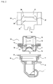
- FIGS. 2 to 4 show an attachment structure for attaching the fuel damper to the fuel pipe, wherein FIG. 2 is an exploded view, FIG. 3 is an assembly view before a winding and tightening operation is performed, and FIG. 4 is an assembly view after the winding and tightening operation is performed.
- FIG. 1 shows the state when the fuel pipes are mounted on the engine
- FIGS. 2 to 4 show the state when the fuel dampers are attached to the fuel pipes, and thus the view of FIG. 1 is upside down with respect to those of FIGS. 2 to 4 .
- a cup portion 6 is exposed to an inside of the fuel pipe 1 so as to open in communication with the fuel pipe 1. Although the cup portion 6 opens downward in the state that the fuel pipe 1 is mounted on the engine, the fuel dam per 10 is attached to the cup portion 6 in the state that it opens upward.
- the fuel damper 10 has an upper case 11, a lower case 12 (a case located on an upper side when it is mounted on the engine is called the upper case, and a case located on a lower side when it is mounted on the engine is called the lower case), and a collar portion 13 around the outer periphery of an intermediate portion of the fuel damper 10 which acts as a joint portion of the upper case 11 and the lower case 12.
- a fuel chamber 15 on the upper case 11 side and an air chamber 16 on the lower case 12 side are separated by a diaphragm 14, a peripheral edge portion of which is clamped in the joint portion.
- a fuel introduction port 16 to the fuel chamber 15 is formed in the upper case 11.
- a spring 17 is accommodated in the air chamber 16 of the lower case 12 to urge the diaphragm 14 to the fuel chamber 15 side.
- the fuel damper 10 When the pressure of the fuel introduced into the fuel chamber 15 is increased, the fuel damper 10 operates to suppress the variation of fuel pressure in such a manner that the diaphragm 14 is displaced to the air chamber 16 side, and increasing the volume of the fuel chamber 15.
- the upper case 11 which is the head portion of the fuel damper 10, is engaged in the cup portion 6 on the fuel pipe 1 side so that the collar portion 8 around the outer periphery of the opening end of the cup portion 6 is joined to the collar portion 13 around the outer periphery of the intermediate portion of the fuel damper 10 as shown in FIG. 3 .
- a resin backup ring 18 is attached to the fuel damper 10 and abutted against the O ring 7.
- a fuel damper fixing clip (clip main body) 20 is used to fix the collar portion 8 on the cup portion 6 side to the collar portion 13 on the fuel damper 10 side in this state.
- FIG. 3 shows the state that the clip 20 is set
- FIG. 4 shows the state that the collar portions 8, 13 are fixed by the clip 20.
- the clip 20 It is sufficient for the clip 20 to cause the O-ring 7 to function to prevent the fuel damper 10 from falling off from the cup portion 6. Accordingly, it is sufficient for the clip 20 to regulate the amount of movement of the fuel damper 10 in an axial direction, and it is not necessary for the clip 20 to cause the fuel damper 10 not to move at all. Therefore, even if the fuel damper 10 rotates, no problem occurs in the performance thereof. However, to prevent the unnecessary rotation of the fuel damper 10, the rotation thereof is regulated by a cutout 33 disposed on the main body of the clip 20 and a projection 9 disposed on the cup portion 6 (refer to FIG. 2 , in which they are dislocated from each other 90°).
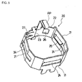
- FIG. 5 is a perspective view of the clip.
- FIGS. 6A and 6B respectively are a schematic plan view and a schematic lateral sectional view of the clip in a diameter-enlarged state (open state) before it is subjected to a winding and tightening operation.
- FIGS. 7A and 7B respectively are a schematic plan view and a schematic lateral sectional view of the clip while it is being subjected to the winding and tightening operation.
- FIGS. 8A and 8B respectively are a schematic plan view and a schematic lateral sectional view of the clip in a diameter-reduced state (closed state) after it is subjected to the winding and tightening operation.
- the clip in any of the views is observed from a bottom surface side (from a lower side in the state that it is mounted on the engine).
- FIG. 9 is a fragmentary view of FIG. 8 when the clip is observed from arrow A.
- the main body of the clip 20 is formed of a sheet member which is bent and formed in a generally square cylindrical shape so as to have a plurality of (at least three) flat portions 21. With this configuration, the main body of the clip 20 covers the outer peripheries of the cup portion 6 and the fuel damper 10, and can be deformed in a winding and tightening direction, and the surfaces thereof at both the ends (arc-shaped overlapping surfaces 22, 23) are overlapped on an inside and an outside.
- Slits 24 are formed in the three flat portions 21 of the main body of the square cylindrical clip 20 so that the collar portions 8, 13 of the cup portion 6 and the fuel damper 10 may enter into the slits 24 and be locked in the diameter-reduced state of the clip 20 in which it is wound and tightened. Accordingly, the slits 24 are disposed at three positions in a peripheral direction.
- a receiving hole 26 is formed in one of the arc-shaped overlapping surfaces 22 and 23 of the main body of the clip 20 (here, the outside overlapping surface 22).
- a claw portion 27 is disposed on the other overlapping surface (here, the inside overlapping surface 23) so as to obliquely project in a direction opposite to the winding and tightening direction on the overlapping surface 22 side.
- the claw portion 27 enters into the receiving hole 26 in the diameter-reduced state of the clip 20 in which it is wound and tightened and locks (prevents) the clip 20 from returning in a direction opposite to the winding and tightening direction in the entered state.
- the main body of the clip 20 has a spring property, is arranged to shift to the diameter-reduced state (state in which the fuel damper 10 is fixed) by the elastically restoring force thereof, and is held in the diameter-enlarged state by attaching a lock pin RP before the fuel damper 10 is fixed (refer to FIG. 5 ). Therefore, when the lock pin RP is removed, the main body of the clip 20 is shifted to the diameter-reduced state by the elastically restoring force thereof.
- the lock pin RP locks the main body of the clip 20 in the diameter-enlarged state in such a manner that it is engaged with a groove on the outside overlapping surface 22 side and with a groove on the inside overlapping surface 23 side, and when the lock pin RP is removed by depressing a handle outward, it can release the main body of the clip 20 from a locked state.
- the fuel damper 10 is engaged in the cup portion 6 on the fuel pipe 1 side, and the collar portion 8 of the cup portion 6 is joined to the collar portion 13 of the fuel damper 10.
- the outer peripheries of the fuel damper 10 and the cup portion 6 are covered with the main body of the square cylindrical clip 20, to which the lock pin RP is attached so that the main body is placed in the diameter-enlarged state (the state of FIGS. 3 , 6A and 6B ).
- the collar portions 8, 13 of the cup portion 6 and the fuel damper 10 enter into the slits 24 of the flat portions 21 and regulate the movement of the collar portions 8, 13 in the axial direction to thereby fix both the collar portions 8, 13. Further, since the collar portions 8, 13 are held at the three positions in the peripheral direction, they can be stably held.
- the collar portions 8, 13 are wound and tightened around the entire peripheries thereof and held by the slits 24 so that they can be securely fixed. Further, since the claw portion 27 enters into the receiving hole 26 in the diameter-reduced state in which the clip 20 is wound and tightened and locks the return of the clip 20, the clip 20 can be securely prevented from being falling off.
- the outside overlapping surface 22 is lifted by the claw portion 27 of the inside overlapping surface 23 while the clip 20 is being wound and tightened as shown in FIG. 7 .
- the force in the winding and tightening direction can be dispersed, so that a brake can be applied to a closing force.
- the collar portions 8, 13 are received on the flat surfaces (bent surfaces 25), they can be prevented from being damaged even if a large assembly force is applied.
- plating coating
- the plating of the collar portion 13 of the fuel damper 10 is more liable to be exfoliated because it is subjected to bending processing more often.
- exfoliation of the plating can be prevented by receiving the collar portion 13 of the fuel damper 10 on the bent surfaces 25.
- the bent surfaces 25 are located in the central portions of the slits 24 in the lengthwise direction thereof, and the portion 28, in which the bent surfaces are not formed, faces the collar portion 13 of the fuel damper 10 at a position retracted from the bent surfaces 25 (refer to FIG. 2 ).
- the portion 28, in which the bent surfaces are not formed acts as a preliminary surface and can receive the collar portion 13 of the fuel damper 10 in the event that the bent surfaces 25 are bent by an abnormal pressure.
- a more safe structure can be obtained.
- a groove 29 is formed between the portion in which the bent surfaces 25 are formed and the portion 28 in which the bent surfaces are not formed.
- the groove 29 extends to a position further retracted from the portion 28 in which the bent surfaces are not formed (refer to FIG. 2 ). Stress concentration can be prevented by the groove 29.
- a flat portion 30 as a stopper is disposed at the root portion of the outside overlapping surface so as to face the projecting end of the inside overlapping surface 23 (refer to FIGS. 8A and 8B ).
- a position confirmation cutout 31 is disposed in the outside overlapping surface 22, and a reference range setting cutout 32 is disposed in the inside overlapping surface 23 (refer to FIG. 9 ). They are used to perform alignment by confirming that the outside cutout 31 is positioned in the inside cutout 32 in the diameter-reduced state. That is, when the cutout 31 is observed from the outside, if the inside overlapping surface 23 cannot be observed from the cutout 31, it is determined that assembly is normally performed. Therefore, the inside cutout 32 is set to a size within a normal range (allowable width). With this arrangement, quality of assembly can be simply checked.
Landscapes
- Engineering & Computer Science (AREA)
- Chemical & Material Sciences (AREA)
- Combustion & Propulsion (AREA)
- Mechanical Engineering (AREA)
- General Engineering & Computer Science (AREA)
- Fuel-Injection Apparatus (AREA)
Abstract
Description
- The present invention relates to a fuel damper fixing clip and particularly, but not exclusively, to a fixing clip for fixing a diaphragm type fuel damper to a cup portion which opens in communication with a fuel pipe in an internal combustion engine. Aspects of the invention relate to a clip, to an apparatus, to a method and to a vehicle.
- A known clip is formed from a sheet member in a U-shape, as a clip for fixing the base end of a fuel injection valve to a fuel pipe in an internal combustion engine. In this arrangement, after the clip is attached to the fuel injection valve, they are mounted on a fuel pipe together.
- However, while the related art clip is used to fix the base end of the fuel injection valve to the fuel pipe, the distal end of the fuel injection valve is fixed to an intake manifold (or cylinder head). Thus, the clip for fixing the fuel injection valve to the fuel pipe is not required to have so much holding force. Accordingly, the clip is formed in the U-shape and arranged so that it can be easily removed.
- In contrast, in a clip for fixing a fuel damper to a fuel pipe, the fuel damper is fixed only to the fuel pipe and is not fixed to any other portion. Thus, the clip must securely fix the fuel damper so that it does not fall off.
- From the above point of view, since the related art U-shaped clip does not have sufficient holding force, there is a possibility that the clip is loosened (deformed) and falls off when an excessively large force is applied thereto. Thus, the clip cannot be applied to the fuel damper fixing clip.
- It is an aim of the present invention to address this issue and to improve upon such known technology. Embodiments of the invention may provide a fuel damper fixing clip which can easily fix a fuel damper and will not fall off. Other aims and advantages of the invention will become apparent from the following description, claims and drawings.
- Aspects of the invention therefore provide an apparatus, a method and a vehicle as claimed in the appended claims.
- According to another aspect of the invention for which protection is sought, there is provided a fuel damper fixing clip for fixing both a collar portion around the outer periphery of an open end of a cup portion and a collar portion around the outer periphery of an intermediate portion of a diaphragm type fuel damper in a state such that a head portion of the fuel damper is engaged in the cup portion, the cup portion being in communication with a fuel pipe for supplying fuel to an internal combustion engine, and the collar portion of the cup portion being joined to the collar portion of the fuel damper, the fuel damper fixing clip comprising a clip main body formed from a sheet member having a plurality of flat portions, and formed in a generally square cylindrical shape, the clip main body surrounds portions of the outer peripheries of the cup portion and the fuel damper and deforms in a tightening direction, the clip main body including two ends overlapped on an outside and an inside surface thereof, slits disposed in the plurality of flat portions of the clip main body, the collar portions of the cup portion and the fuel damper being disposed therein and locked in a diameter-reduced state of the clip main body in which the clip main body is tightened, a receiving hole formed in one of the ends of the clip main body and a claw portion disposed on the other end of the clip main body obliquely projecting in a direction opposite to the tightening direction, the claw portion being disposed in the receiving hole in the diameter-reduced state in which the clip main body is tightened, and locking the clip main body in the diameter-reduced state in which the collar portions are fixed.
- In an embodiment, bent surfaces are bent inward adjacent the slits, and the collar portion of the fuel damper is abutted against the bent surfaces.
- In an embodiment, the bent surfaces are located in central portions of the slits in a lengthwise direction thereof, and a portion of each slit, in which the bent surfaces are not formed, faces the collar portion of the fuel damper at a position retracted from the bent surfaces.
- In an embodiment, a groove is formed between the portion in which the bent surfaces are formed and the portion in which the bent surfaces are not formed, the groove extending to a position further retracted from the portion in which the bent surfaces are not formed.
- In an embodiment, the clip main body is held in a diameter-enlarged state by attaching a lock pin, and shifts to a diameter-reduced state by a restoring force thereof by removing the lock pin.
- In an embodiment, the slits are disposed at three positions in a peripheral direction.
- In an embodiment, a flat portion as a stopper is disposed at a root portion of the outside overlapped surface of one end of the clip main body so as to face the projecting end of the inside overlapped surface of the other end of the clip main body.
- In an embodiment, the overlapped surfaces are formed in an arc shape.
- In an embodiment, a position confirmation cutout is formed in the outside overlapped surface and a reference range setting cutout is formed in the inside overlapped surface to confirm that the outside cutout is positioned in the inside cutout in the diameter-reduced state.
- According to a further aspect of the invention for which protection is sought, there is provided a method of fixing both a collar portion around the outer periphery of an open end of a cup portion and a collar portion around the outer periphery of an intermediate portion of a diaphragm type fuel damper in a state such that a head portion of the fuel damper is engaged in the cup portion and the collar portion of the cup portion is joined to the collar portion of the fuel damper, the cup portion being in communication with a fuel pipe for supplying fuel to an internal combustion engine, the method comprising providing a fuel damper fixing clip having a clip main body formed from a sheet member having a plurality of flat portions and formed in a generally square cylindrical shape, slits disposed in the plurality of flat portions of the clip main body, a receiving hole formed in one end of the clip main body, and a claw portion disposed on another end of the clip main body obliquely projecting in a direction opposite to a tightening direction, surrounding portions of the outer peripheries of the cup portion and the fuel damper with the clip main body, disposing the collar portions of the cup portion and the fuel damper in the slits, overlapping the two ends of the clip main body on an outside and an inside surface thereof, deforming the clip main body in a tightening direction in a diameter-reduced state, disposing the claw portion in the receiving hole in the diameter-reduced state in which the clip main body is tightened and locking the clip main body in the diameter-reduced state in which the collar portions are fixed.
- The method may comprise abutting the collar portion of the fuel damper against bent surfaces that are bent inward adjacent the slits.
- The method may comprise attaching a locking pin and holding the clip main body in a diameter-enlarged state and removing the locking pin and shifting to the diameter-reduced state by a restoring force of the clip main body.
- The method may comprise positioning a position confirmation cutout formed in the outside overlapped surface in a reference range setting cutout formed in the inside overlapped surface, in the diameter-reduced state.
- For example, a fuel damper fixing clip may be provided for fixing both a collar portion around the outer periphery of an open end of a cup portion and a collar portion around the outer periphery of an intermediate portion of a diaphragm type fuel damper in a state such that a head portion of the fuel damper is engaged in the cup portion. The cup portion is in communication with a fuel pipe for supplying fuel to an internal combustion engine. The collar portion of the cup portion is joined to the collar portion of the fuel damper. The fuel damper fixing clip includes a clip main body formed from a sheet member having a plurality of flat portions, and formed in a generally square cylindrical shape. The clip main body surrounds portions of the outer peripheries of the cup portion and the fuel damper and deforms in a tightening direction. The clip main body includes two ends overlapped on an outside and an inside surface thereof. Slits are disposed in the plurality of flat portions of the clip main body, and the collar portions of the cup portion and the fuel damper are disposed therein and locked in a diameter-reduced state of the clip main body in which the clip main body is tightened. A receiving hole is formed in one of the ends of the clip main body. A claw portion is disposed on the other end of the clip main body obliquely projecting in a direction opposite to the tightening direction. The claw portion is disposed in the receiving hole in the diameter-reduced state in which the clip main body is tightened, and locks the clip main body in the diameter-reduced state in which the collar portions are fixed.
- In another embodiment, there is provided a method of fixing both a collar portion around the outer periphery of an open end of a cup portion and a collar portion around the outer periphery of an intermediate portion of a diaphragm type fuel damper in a state such that a head portion of the fuel damper is engaged in the cup portion and the collar portion of the cup portion is joined to the collar portion of the fuel damper. The cup portion is in communication with a fuel pipe for supplying fuel to an internal combustion engine. The method includes providing a fuel damper fixing clip having a clip main body formed from a sheet member having a plurality of flat portions and formed in a generally square cylindrical shape, slits disposed in the plurality of flat portions of the clip main body, a receiving hole formed in one end of the clip m ain body, and a claw portion disposed on another end of the clip main body obliquely projecting in a direction opposite to a tightening direction. The method further includes surrounding portions of the outer peripheries of the cup portion and the fuel damper with the clip main body, disposing the collar portions of the cup portion and the fuel damper in the slits, overlapping the two ends of the clip main body on an outside and an inside surface thereof, deforming the clip main body in a tightening direction in a diameter-reduced state, disposing the claw portion in the receiving hole in the diameter-reduced state in which the clip main body is tightened, and locking the clip main body in the diameter-reduced state in which the collar portions are fixed.
- According to embodiments of the present invention, since the clip is wound and tightened from the entire periphery thereof and held by the slits, it can be securely fixed. Further, since the claw portion enters into the receiving hole in a diameter-reduced state in which the clip is wound and tightened and locks the return of the clip, the claw portion can be securely fixed.
- Within the scope of this application it is envisaged that the various aspects, embodiments, examples, feature and alternatives set out in the preceding paragraphs, in the claims and/or in the following description and drawings may be taken individually or in any combination thereof.
- The present invention will now be described, by way of example only, with reference to the accompanying drawings in which:
-
FIG. 1 is a perspective view showing the state in which fuel dampers are attached to fuel pipes; -
FIG. 2 is an exploded view showing an attachment structure for attaching the fuel damper to the fuel pipe; -
FIG. 3 is an assembly view showing an attachment structure for attaching the fuel damper to the fuel pipe, before a winding and tightening operation is performed; -
FIG. 4 an assembly view showing an attachment structure for attaching the fuel damper to the fuel pipe, after the winding and tightening operation is performed; -
FIG. 5 is a perspective view of a clip; -
FIGS. 6A and 6B respectively show a schematic plan view and a schematic lateral sectional view of the clip in a diameter-enlarged state (open state) before it is subjected to the winding and tightening operation; -
FIGS. 7A and 7B respectively show a schematic plan view and a schematic lateral sectional view of the clip while it is being subjected to the winding and tightening operation; -
FIGS. 8A and 8B respectively show a schematic plan view and a schematic lateral sectional view of the clip in a diameter-reduced state (closed state) after it is subjected to the winding and tightening operation; and -
FIG. 9 is a fragmentary view taken in the direction of arrow A inFIG. 8A . -
FIG. 1 shows fuel pipes of an internal combustion engine in an embodiment of the present invention. The fuel pipes are employed in a V-type six-cylinder engine. The fuel pipes (fuel gallery) 1 are disposed at respective banks and communicate with each other through afuel tube 2 and are connected to a fuel tube 4 from a fuel pump (not shown) throughconnectors 3. - The base ends of each of three sets of
fuel injection valves 5 are attached to arespective fuel pipe 1, as is afuel damper 10. An assembly of thefuel pipes 1, thefuel injection valves 5, and thefuel dampers 10 is mounted on the engine, and the distal ends of thefuel injection valves 5 are attached to the intake manifolds of the engine. -
FIGS. 2 to 4 show an attachment structure for attaching the fuel damper to the fuel pipe, whereinFIG. 2 is an exploded view,FIG. 3 is an assembly view before a winding and tightening operation is performed, andFIG. 4 is an assembly view after the winding and tightening operation is performed.FIG. 1 shows the state when the fuel pipes are mounted on the engine, whereasFIGS. 2 to 4 show the state when the fuel dampers are attached to the fuel pipes, and thus the view ofFIG. 1 is upside down with respect to those ofFIGS. 2 to 4 . - Referring to
FIG. 2 , acup portion 6 is exposed to an inside of thefuel pipe 1 so as to open in communication with thefuel pipe 1. Although thecup portion 6 opens downward in the state that thefuel pipe 1 is mounted on the engine, the fuel dam per 10 is attached to thecup portion 6 in the state that it opens upward. - An O-
ring 7 is attached around the inner periphery of thecup portion 6. Further, acollar portion 8 is disposed around the outer periphery of the opening end of thecup portion 6. Thefuel damper 10 has anupper case 11, a lower case 12 (a case located on an upper side when it is mounted on the engine is called the upper case, and a case located on a lower side when it is mounted on the engine is called the lower case), and acollar portion 13 around the outer periphery of an intermediate portion of thefuel damper 10 which acts as a joint portion of theupper case 11 and thelower case 12. Afuel chamber 15 on theupper case 11 side and anair chamber 16 on thelower case 12 side are separated by adiaphragm 14, a peripheral edge portion of which is clamped in the joint portion. Afuel introduction port 16 to thefuel chamber 15 is formed in theupper case 11. Aspring 17 is accommodated in theair chamber 16 of thelower case 12 to urge thediaphragm 14 to thefuel chamber 15 side. - When the pressure of the fuel introduced into the
fuel chamber 15 is increased, thefuel damper 10 operates to suppress the variation of fuel pressure in such a manner that thediaphragm 14 is displaced to theair chamber 16 side, and increasing the volume of thefuel chamber 15. - The
upper case 11, which is the head portion of thefuel damper 10, is engaged in thecup portion 6 on thefuel pipe 1 side so that thecollar portion 8 around the outer periphery of the opening end of thecup portion 6 is joined to thecollar portion 13 around the outer periphery of the intermediate portion of thefuel damper 10 as shown inFIG. 3 . Aresin backup ring 18 is attached to thefuel damper 10 and abutted against theO ring 7. - A fuel damper fixing clip (clip main body) 20 is used to fix the
collar portion 8 on thecup portion 6 side to thecollar portion 13 on thefuel damper 10 side in this state.FIG. 3 shows the state that theclip 20 is set, andFIG. 4 shows the state that thecollar portions clip 20. - It is sufficient for the
clip 20 to cause the O-ring 7 to function to prevent thefuel damper 10 from falling off from thecup portion 6. Accordingly, it is sufficient for theclip 20 to regulate the amount of movement of thefuel damper 10 in an axial direction, and it is not necessary for theclip 20 to cause thefuel damper 10 not to move at all. Therefore, even if thefuel damper 10 rotates, no problem occurs in the performance thereof. However, to prevent the unnecessary rotation of thefuel damper 10, the rotation thereof is regulated by acutout 33 disposed on the main body of theclip 20 and a projection 9 disposed on the cup portion 6 (refer toFIG. 2 , in which they are dislocated from each other 90°). - A structure of the fuel
damper fixing clip 20 will be explained below in detail.FIG. 5 is a perspective view of the clip.FIGS. 6A and 6B respectively are a schematic plan view and a schematic lateral sectional view of the clip in a diameter-enlarged state (open state) before it is subjected to a winding and tightening operation.FIGS. 7A and 7B respectively are a schematic plan view and a schematic lateral sectional view of the clip while it is being subjected to the winding and tightening operation.FIGS. 8A and 8B respectively are a schematic plan view and a schematic lateral sectional view of the clip in a diameter-reduced state (closed state) after it is subjected to the winding and tightening operation. The clip in any of the views is observed from a bottom surface side (from a lower side in the state that it is mounted on the engine).FIG. 9 is a fragmentary view ofFIG. 8 when the clip is observed from arrow A. - The main body of the
clip 20 is formed of a sheet member which is bent and formed in a generally square cylindrical shape so as to have a plurality of (at least three)flat portions 21. With this configuration, the main body of theclip 20 covers the outer peripheries of thecup portion 6 and thefuel damper 10, and can be deformed in a winding and tightening direction, and the surfaces thereof at both the ends (arc-shaped overlapping surfaces 22, 23) are overlapped on an inside and an outside. -
Slits 24 are formed in the threeflat portions 21 of the main body of the squarecylindrical clip 20 so that thecollar portions cup portion 6 and thefuel damper 10 may enter into theslits 24 and be locked in the diameter-reduced state of theclip 20 in which it is wound and tightened. Accordingly, theslits 24 are disposed at three positions in a peripheral direction. - The abutment sides of the
slits 24 against which thecollar portion 13 of thefuel damper 10 is abutted have bentsurfaces 25 bent inward, and thecollar portion 13 of thefuel damper 10 is abutted against theslits 24 at the bent surfaces 25. A receivinghole 26 is formed in one of the arc-shaped overlapping surfaces 22 and 23 of the main body of the clip 20 (here, the outside overlapping surface 22). - A
claw portion 27 is disposed on the other overlapping surface (here, the inside overlapping surface 23) so as to obliquely project in a direction opposite to the winding and tightening direction on the overlappingsurface 22 side. Theclaw portion 27 enters into the receivinghole 26 in the diameter-reduced state of theclip 20 in which it is wound and tightened and locks (prevents) theclip 20 from returning in a direction opposite to the winding and tightening direction in the entered state. - Further, the main body of the
clip 20 has a spring property, is arranged to shift to the diameter-reduced state (state in which thefuel damper 10 is fixed) by the elastically restoring force thereof, and is held in the diameter-enlarged state by attaching a lock pin RP before thefuel damper 10 is fixed (refer toFIG. 5 ). Therefore, when the lock pin RP is removed, the main body of theclip 20 is shifted to the diameter-reduced state by the elastically restoring force thereof. Note that the lock pin RP locks the main body of theclip 20 in the diameter-enlarged state in such a manner that it is engaged with a groove on the outside overlappingsurface 22 side and with a groove on the inside overlappingsurface 23 side, and when the lock pin RP is removed by depressing a handle outward, it can release the main body of theclip 20 from a locked state. - Accordingly, the
fuel damper 10 is engaged in thecup portion 6 on thefuel pipe 1 side, and thecollar portion 8 of thecup portion 6 is joined to thecollar portion 13 of thefuel damper 10. In this state, the outer peripheries of thefuel damper 10 and thecup portion 6 are covered with the main body of the squarecylindrical clip 20, to which the lock pin RP is attached so that the main body is placed in the diameter-enlarged state (the state ofFIGS. 3 ,6A and 6B ). - The bent surfaces 25 of the
slits 24 ride on the end surface of thelower case 12 of thefuel damper 10, thereby positioning is performed in an axial direction. When the lock pin RP is removed from this state (diameter-enlarged state ofFIG. 6 ), the diameter of the main body of theclip 20 is reduced by the restoring force thereof, and the main body of theclip 20 is placed in the diameter-reduced state ofFIG. 8 through the process ofFIG. 7 , whereby thecup portion 6 and thefuel damper 10 are wound and tightened. - The
collar portions cup portion 6 and thefuel damper 10 enter into theslits 24 of theflat portions 21 and regulate the movement of thecollar portions collar portions collar portions - Further, in the diameter-reduced state of
FIG. 8 , theclaw portion 27 of the inside overlappingsurface 23 enters into the receivinghole 26 of the outside overlappingsurface 22. Thus, when the inside overlappingsurface 23 tends to move in a diameter-enlarged direction, the movement thereof is prevented by theclaw portion 27 which is caught by the edge of the receivinghole 26. Accordingly, the wound and tightened state is not released. - Therefore, the
collar portions slits 24 so that they can be securely fixed. Further, since theclaw portion 27 enters into the receivinghole 26 in the diameter-reduced state in which theclip 20 is wound and tightened and locks the return of theclip 20, theclip 20 can be securely prevented from being falling off. - Further, the outside overlapping
surface 22 is lifted by theclaw portion 27 of the inside overlappingsurface 23 while theclip 20 is being wound and tightened as shown inFIG. 7 . Thus, since the outside overlappingsurface 23 is lifted once and then fallen, the force in the winding and tightening direction can be dispersed, so that a brake can be applied to a closing force. This prevents, for example, thefuel damper 10 being damaged due to a closing force being abruptly applied. Accordingly, thecollar portions - Further, since the abutment sides of the
slits 24 against which thecollar portion 13 of thefuel damper 10 is abutted have thebent surfaces 25 bent inward and thecollar portion 13 of thefuel damper 10 is abutted against theslits 24 through thebent surfaces 25, the following advantages can be obtained. - Although a fuel injection valve can be inserted after a clip is inserted thereinto, this method cannot be applied to the fuel damper. Accordingly, when the
clip 20 cannot be fixed before it is wound and tightened, workability is deteriorated (it must be positioned so that it can be fixed at a correct position). Thus, the workability can be improved by positioning theclip 20 on the bent surfaces 25. - Further, since the
collar portions collar portion 13 of thefuel damper 10 and thecollar portion 8 of thecup portion 6 which are received by the flat surfaces (bent surfaces 25), respectively, the plating of thecollar portion 13 of thefuel damper 10 is more liable to be exfoliated because it is subjected to bending processing more often. Thus, there is also an advantage in that exfoliation of the plating can be prevented by receiving thecollar portion 13 of thefuel damper 10 on the bent surfaces 25. - Further, the attachment structure will be explained in detail. The bent surfaces 25 are located in the central portions of the
slits 24 in the lengthwise direction thereof, and theportion 28, in which the bent surfaces are not formed, faces thecollar portion 13 of thefuel damper 10 at a position retracted from the bent surfaces 25 (refer toFIG. 2 ). With this arrangement, theportion 28, in which the bent surfaces are not formed, acts as a preliminary surface and can receive thecollar portion 13 of thefuel damper 10 in the event that thebent surfaces 25 are bent by an abnormal pressure. Thus, a more safe structure can be obtained. - Further, a
groove 29 is formed between the portion in which thebent surfaces 25 are formed and theportion 28 in which the bent surfaces are not formed. Thegroove 29 extends to a position further retracted from theportion 28 in which the bent surfaces are not formed (refer toFIG. 2 ). Stress concentration can be prevented by thegroove 29. - Further, a
flat portion 30 as a stopper is disposed at the root portion of the outside overlapping surface so as to face the projecting end of the inside overlapping surface 23 (refer toFIGS. 8A and 8B ). With this arrangement, even if the projecting end of the inside overlappingsurface 23 overruns when theclip 20 is wound and tightened, the projecting end is abutted against theflat portion 30 as the stopper so that a stopper function can be obtained. Accordingly, damage of the inside overlappingsurface 23 due to the overrun can be prevented. - Further, a
position confirmation cutout 31 is disposed in the outside overlappingsurface 22, and a referencerange setting cutout 32 is disposed in the inside overlapping surface 23 (refer toFIG. 9 ). They are used to perform alignment by confirming that theoutside cutout 31 is positioned in theinside cutout 32 in the diameter-reduced state. That is, when thecutout 31 is observed from the outside, if the inside overlappingsurface 23 cannot be observed from thecutout 31, it is determined that assembly is normally performed. Therefore, theinside cutout 32 is set to a size within a normal range (allowable width). With this arrangement, quality of assembly can be simply checked. - While the invention has been disclosed with reference to certain embodiments, numerous modifications, alterations, and changes to the described embodiments are possible without departing from the sphere and scope of the invention, as defined in the appended claims and their equivalents thereof. Accordingly, it is intended that the invention not be limited to the described embodiments, but that it have the full scope defined by the language of the following claims.
- This application claims priority from Japanese Patent Application No.
2007-211822, filed 15th August 2007
Claims (14)
- An apparatus for fixing both a collar portion around the outer periphery of an open end of a cup portion and a collar portion around the outer periphery of an intermediate portion of a diaphragm type fuel damper in a state such that a head portion of the fuel damper is engaged in the cup portion, the cup portion being in communication with a fuel pipe for supplying fuel to an internal combustion engine, and the collar portion of the cup portion being joined to the collar portion of the fuel damper, the apparatus comprising:a clip main body formed in a generally square cylindrical shape from a sheet member having a plurality of flat portions, the clip main body surrounding portions of the outer peripheries of the cup portion and the fuel damper and being deformable in a tightening direction, the clip main body comprising two ends overlapped on an outside and an inside surface thereof;slits disposed in the plurality of flat portions of the clip main body, the collar portions of the cup portion and the fuel damper being arranged to be disposed therein and locked in a diameter-reduced state of the clip main body in which the clip main body is tightened;a receiving hole formed in one of the ends of the clip main body; anda claw portion disposed on the other end of the clip main body obliquely projecting in a direction opposite to the tightening direction, the claw portion being disposed in the receiving hole in the diameter-reduced state in which the clip main body is tightened and being arranged to lock the clip main body in the diameter-reduced state in which the collar portions are fixed.
- An apparatus as claimed in claim 1, wherein bent surfaces are bent inward adjacent the slits, and the collar portion of the fuel damper is abutted against the bent surfaces.
- An apparatus as claimed in claim 2, wherein the bent surfaces are located in central portions of the slits in a lengthwise direction thereof, and a portion of each slit, in which the bent surfaces are not formed, faces the collar portion of the fuel damper at a position retracted from the bent surfaces.
- An apparatus as claimed in claim 3, wherein a groove is formed between the portion in which the bent surfaces are formed and the portion in which the bent surfaces are not formed, the groove extending to a position further retracted from the portion in which the bent surfaces are not formed.
- An apparatus as claimed in any preceding claim, wherein the clip main body is held in a diameter-enlarged state by attaching a lock pin, and shifts to a diameter-reduced state by a restoring force thereof by removing the lock pin.
- An apparatus as claimed in any preceding claim, wherein the slits are disposed at three positions in a peripheral direction.
- An apparatus as claimed in any preceding claim, wherein a flat portion as a stopper is disposed at a root portion of the outside overlapped surface of one end of the clip main body so as to face the projecting end of the inside overlapped surface of the other end of the clip main body.
- An apparatus as claimed in any preceding claim, wherein the overlapped surfaces are formed in an arc shape.
- An apparatus as claimed in any preceding claim, wherein a position confirmation cutout is formed in the outside overlapped surface and a reference range setting cutout is formed in the inside overlapped surface to confirm that the outside cutout is positioned in the inside cutout in the diameter-reduced state.
- A method of fixing both a collar portion around the outer periphery of an open end of a cup portion and a collar portion around the outer periphery of an intermediate portion of a diaphragm type fuel damper in a state such that a head portion of the fuel damper is engaged in the cup portion and the collar portion of the cup portion is joined to the collar portion of the fuel damper, the cup portion being in communication with a fuel pipe for supplying fuel to an internal combustion engine, the method comprising:providing a fuel damper fixing clip having a clip main body formed from a sheet member having a plurality of flat portions and formed in a generally square cylindrical shape, slits disposed in the plurality of flat portions of the clip main body, a receiving hole formed in one end of the clip main body, and a claw portion disposed on another end of the clip main body obliquely projecting in a direction opposite to a tightening direction;surrounding portions of the outer peripheries of the cup portion and the fuel damper with the clip main body;disposing the collar portions of the cup portion and the fuel damper in the slits;overlapping the two ends of the clip main body on an outside and an inside surface thereof;deforming the clip main body in a tightening direction in a diameter-reduced state;disposing the claw portion in the receiving hole in the diameter-reduced state in which the clip main body is tightened; andlocking the clip main body in the diameter-reduced state in which the collar portions are fixed.
- A method as claimed in claim 10, comprising abutting the collar portion of the fuel damper against bent surfaces that are bent inward adjacent the slits.
- A method as claimed in claim 10 or claim 11, comprising:attaching a locking pin and holding the clip m ain body in a diameter-enlarged state; andremoving the locking pin and shifting to the diameter-reduced state by a restoring force of the clip main body.
- A method as claimed in any of claims 10 to 12, comprising positioning a position confirmation cutout formed in the outside overlapped surface in a reference range setting cutout formed in the inside overlapped surface, in the diameter-reduced state.
- A vehicle having an apparatus as claimed in any of claims 1 to 9.
Applications Claiming Priority (1)
| Application Number | Priority Date | Filing Date | Title |
|---|---|---|---|
| JP2007211822A JP4862778B2 (en) | 2007-08-15 | 2007-08-15 | Fuel damper fixing clip |
Publications (2)
| Publication Number | Publication Date |
|---|---|
| EP2025925A1 true EP2025925A1 (en) | 2009-02-18 |
| EP2025925B1 EP2025925B1 (en) | 2010-04-28 |
Family
ID=39776337
Family Applications (1)
| Application Number | Title | Priority Date | Filing Date |
|---|---|---|---|
| EP08161807A Active EP2025925B1 (en) | 2007-08-15 | 2008-08-05 | Fuel damper fixing clip |
Country Status (5)
| Country | Link |
|---|---|
| US (1) | US7909021B2 (en) |
| EP (1) | EP2025925B1 (en) |
| JP (1) | JP4862778B2 (en) |
| CN (1) | CN101368535B (en) |
| DE (1) | DE602008001088D1 (en) |
Families Citing this family (11)
| Publication number | Priority date | Publication date | Assignee | Title |
|---|---|---|---|---|
| JP4862778B2 (en) * | 2007-08-15 | 2012-01-25 | 日産自動車株式会社 | Fuel damper fixing clip |
| JP5231380B2 (en) * | 2009-11-09 | 2013-07-10 | 株式会社デンソー | Damper assembly, high-pressure pump using the same, and method for manufacturing high-pressure pump |
| DE102010034411B4 (en) * | 2010-08-14 | 2018-10-11 | Audi Ag | Internal combustion engine with injection valve |
| AU333456S (en) * | 2010-10-05 | 2010-11-05 | Sitka Dev Pty Ltd | Pipe hanger clamp |
| AU334095S (en) * | 2010-11-16 | 2010-12-09 | Sitka Dev Pty Ltd | Pipe hanger clamp |
| AU337464S (en) * | 2011-06-06 | 2011-07-01 | Sitka Dev Pty Ltd | Pipe hanger clamp |
| WO2013034450A1 (en) * | 2011-09-08 | 2013-03-14 | Continental Automotive Gmbh | Fuel injector and fuel injector assembly |
| CN103410644B (en) * | 2013-07-10 | 2015-10-28 | 奇瑞汽车股份有限公司 | A kind of fuel damper and apply the oil passage connection structure of this buffer |
| USD723362S1 (en) * | 2013-09-03 | 2015-03-03 | Gripple Limited | Side loading pipe hanger |
| JP6636858B2 (en) * | 2016-05-31 | 2020-01-29 | 株式会社Subaru | Fuel supply system for direct injection engine |
| JP7852031B2 (en) * | 2022-02-24 | 2026-04-27 | 株式会社ミクニ | fuel supply device |
Citations (8)
| Publication number | Priority date | Publication date | Assignee | Title |
|---|---|---|---|---|
| US5094211A (en) * | 1988-09-28 | 1992-03-10 | Siemens Automotive L.P. | Automotive fuel rail assemblies with integral means for mounting fuel regulator |
| EP0669459A2 (en) * | 1994-02-25 | 1995-08-30 | Siemens Automotive Corporation | Fuel rail assembly |
| US5577478A (en) * | 1995-11-03 | 1996-11-26 | Walbro Corporation | Integrated fuel pressure regulator and rail assembly |
| US5842450A (en) * | 1998-04-13 | 1998-12-01 | Ford Motor Company | Fuel regulator retaining clip |
| WO1999004161A1 (en) * | 1997-07-16 | 1999-01-28 | Siemens Canada Limited | Device for mounting a pressure regulator on a plastic fuel line |
| WO1999061783A1 (en) * | 1998-05-28 | 1999-12-02 | Siemens Automotive Corporation | Fuel rail damper |
| DE20104270U1 (en) * | 2001-03-13 | 2002-07-18 | Robert Bosch Gmbh, 70469 Stuttgart | Connection of two coaxially arranged elements of a fuel supply system of an internal combustion engine |
| JP2007211822A (en) | 2006-02-07 | 2007-08-23 | Nsk Ltd | Method for assembling linear guide bearing device and temporary shaft for lubricant supply unit |
Family Cites Families (15)
| Publication number | Priority date | Publication date | Assignee | Title |
|---|---|---|---|---|
| US1441154A (en) * | 1922-04-17 | 1923-01-02 | Henry W Johnson | Hose clamp |
| US4557024A (en) * | 1984-02-06 | 1985-12-10 | 501 Evelyn Investments Ltd. | Clamp for hose, tubing, or the like |
| US4483556A (en) * | 1982-09-22 | 1984-11-20 | Dayco Corporation | Hose clamp for a wire reinforced hose |
| JPH03131708A (en) * | 1989-10-17 | 1991-06-05 | Mitsubishi Motors Corp | Confirming and simultaneous inspecting method for many assemblies |
| JPH04275836A (en) * | 1991-02-27 | 1992-10-01 | Suzuki Motor Corp | Pressure fitting/caulking device |
| JP3287102B2 (en) * | 1994-02-25 | 2002-05-27 | 東海ゴム工業株式会社 | Hose clamp and connecting device using the same |
| US6539920B1 (en) * | 2000-05-04 | 2003-04-01 | Siemens Automotive Corporation | Retaining clip |
| CN100374357C (en) * | 2003-01-14 | 2008-03-12 | 汉斯厄蒂克机械和设备工厂有限公司 | Open hose clamp with plastically deformable ears and method of manufacture |
| USD580748S1 (en) * | 2003-07-14 | 2008-11-18 | End Of The Road, Inc. | Molded clamp |
| JP2005163627A (en) * | 2003-12-02 | 2005-06-23 | Mitsubishi Electric Corp | Fuel injection valve device |
| DE10359299A1 (en) * | 2003-12-17 | 2005-08-25 | Robert Bosch Gmbh | support element |
| DE102004015042A1 (en) * | 2004-03-26 | 2005-10-13 | Robert Bosch Gmbh | support element |
| JP2006038092A (en) * | 2004-07-27 | 2006-02-09 | Togo Seisakusho Corp | Hose clamp |
| JP2007180235A (en) * | 2005-12-27 | 2007-07-12 | Yamaha Corp | Semiconductor device and manufacturing method thereof |
| JP4862778B2 (en) * | 2007-08-15 | 2012-01-25 | 日産自動車株式会社 | Fuel damper fixing clip |
-
2007
- 2007-08-15 JP JP2007211822A patent/JP4862778B2/en active Active
-
2008
- 2008-07-18 US US12/175,617 patent/US7909021B2/en active Active
- 2008-08-05 EP EP08161807A patent/EP2025925B1/en active Active
- 2008-08-05 DE DE602008001088T patent/DE602008001088D1/en active Active
- 2008-08-13 CN CN2008101334004A patent/CN101368535B/en active Active
Patent Citations (10)
| Publication number | Priority date | Publication date | Assignee | Title |
|---|---|---|---|---|
| US5094211A (en) * | 1988-09-28 | 1992-03-10 | Siemens Automotive L.P. | Automotive fuel rail assemblies with integral means for mounting fuel regulator |
| EP0669459A2 (en) * | 1994-02-25 | 1995-08-30 | Siemens Automotive Corporation | Fuel rail assembly |
| US5577478A (en) * | 1995-11-03 | 1996-11-26 | Walbro Corporation | Integrated fuel pressure regulator and rail assembly |
| WO1999004161A1 (en) * | 1997-07-16 | 1999-01-28 | Siemens Canada Limited | Device for mounting a pressure regulator on a plastic fuel line |
| US5842450A (en) * | 1998-04-13 | 1998-12-01 | Ford Motor Company | Fuel regulator retaining clip |
| WO1999061783A1 (en) * | 1998-05-28 | 1999-12-02 | Siemens Automotive Corporation | Fuel rail damper |
| EP1084345A1 (en) * | 1998-05-28 | 2001-03-21 | Siemens Automotive Corporation | Fuel rail damper |
| DE20104270U1 (en) * | 2001-03-13 | 2002-07-18 | Robert Bosch Gmbh, 70469 Stuttgart | Connection of two coaxially arranged elements of a fuel supply system of an internal combustion engine |
| EP1373708A1 (en) * | 2001-03-13 | 2004-01-02 | Robert Bosch Gmbh | Connection by means of a retaining clip of two elements of a fuel supply system of an internal combustion engine that are coaxially disposed one behind the other |
| JP2007211822A (en) | 2006-02-07 | 2007-08-23 | Nsk Ltd | Method for assembling linear guide bearing device and temporary shaft for lubricant supply unit |
Also Published As
| Publication number | Publication date |
|---|---|
| US20090044784A1 (en) | 2009-02-19 |
| CN101368535B (en) | 2012-02-15 |
| CN101368535A (en) | 2009-02-18 |
| DE602008001088D1 (en) | 2010-06-10 |
| EP2025925B1 (en) | 2010-04-28 |
| JP4862778B2 (en) | 2012-01-25 |
| JP2009047020A (en) | 2009-03-05 |
| US7909021B2 (en) | 2011-03-22 |
Similar Documents
| Publication | Publication Date | Title |
|---|---|---|
| EP2025925B1 (en) | Fuel damper fixing clip | |
| US9631594B2 (en) | Anti-rotation clip for a twist lock fuel injector | |
| US9243731B2 (en) | Pipe clamp, in particular profile clamp | |
| US10591099B2 (en) | Fuel line connector and method of making | |
| US7862090B1 (en) | Plug-in fitting for direct connection to housing | |
| US8479710B2 (en) | Injector to fuel rail coupling structure for high pressure direct injection engines | |
| US6923162B2 (en) | Securing sleeve for a fuel injection system | |
| US20110232609A1 (en) | Integrated fuel injector orientation and retention device | |
| US10487786B2 (en) | Fuel injection assembly for an internal combustion engine | |
| US8821185B2 (en) | Locking device for a connecting arrangement | |
| EP2497938B1 (en) | Fuel delivery pipe | |
| US20050022771A1 (en) | Manifold sensor retention system | |
| US20210260991A1 (en) | Refueling port | |
| US7320301B1 (en) | Clock and anchor pipe fitting and method | |
| CN108223223A (en) | For measuring the valve of fluid | |
| US10760540B2 (en) | Arrangement for supplying fuel to an engine | |
| EP4042052B1 (en) | Quick connector with a replaceable restriction orifice | |
| EP1803928B1 (en) | Fuel injection system and fuel injection valve device used in fuel injection system | |
| US6539786B1 (en) | Sensor attachment arrangement having extending members | |
| JP2003343388A (en) | Joint structure for connecting the fuel pipe section to the fuel injection device | |
| US8226016B2 (en) | Fuel injector assembly | |
| WO2018007188A1 (en) | Fuel injector retention arrangement | |
| EP2017463B1 (en) | Fuel injectors and method of installing fuel injectors to an engine | |
| CN107110091B (en) | Delivery pipe | |
| CN112664376B (en) | joint connection structure |
Legal Events
| Date | Code | Title | Description |
|---|---|---|---|
| PUAI | Public reference made under article 153(3) epc to a published international application that has entered the european phase |
Free format text: ORIGINAL CODE: 0009012 |
|
| AK | Designated contracting states |
Kind code of ref document: A1 Designated state(s): AT BE BG CH CY CZ DE DK EE ES FI FR GB GR HR HU IE IS IT LI LT LU LV MC MT NL NO PL PT RO SE SI SK TR |
|
| AX | Request for extension of the european patent |
Extension state: AL BA MK RS |
|
| 17P | Request for examination filed |
Effective date: 20090818 |
|
| AKX | Designation fees paid |
Designated state(s): DE FR GB |
|
| GRAP | Despatch of communication of intention to grant a patent |
Free format text: ORIGINAL CODE: EPIDOSNIGR1 |
|
| GRAS | Grant fee paid |
Free format text: ORIGINAL CODE: EPIDOSNIGR3 |
|
| GRAA | (expected) grant |
Free format text: ORIGINAL CODE: 0009210 |
|
| AK | Designated contracting states |
Kind code of ref document: B1 Designated state(s): DE FR GB |
|
| REG | Reference to a national code |
Ref country code: GB Ref legal event code: FG4D |
|
| REF | Corresponds to: |
Ref document number: 602008001088 Country of ref document: DE Date of ref document: 20100610 Kind code of ref document: P |
|
| PLBE | No opposition filed within time limit |
Free format text: ORIGINAL CODE: 0009261 |
|
| STAA | Information on the status of an ep patent application or granted ep patent |
Free format text: STATUS: NO OPPOSITION FILED WITHIN TIME LIMIT |
|
| 26N | No opposition filed |
Effective date: 20110131 |
|
| REG | Reference to a national code |
Ref country code: FR Ref legal event code: PLFP Year of fee payment: 9 |
|
| REG | Reference to a national code |
Ref country code: FR Ref legal event code: PLFP Year of fee payment: 10 |
|
| REG | Reference to a national code |
Ref country code: FR Ref legal event code: PLFP Year of fee payment: 11 |
|
| PGFP | Annual fee paid to national office [announced via postgrant information from national office to epo] |
Ref country code: DE Payment date: 20240723 Year of fee payment: 17 |
|
| PGFP | Annual fee paid to national office [announced via postgrant information from national office to epo] |
Ref country code: GB Payment date: 20240723 Year of fee payment: 17 |
|
| PGFP | Annual fee paid to national office [announced via postgrant information from national office to epo] |
Ref country code: FR Payment date: 20240723 Year of fee payment: 17 |
|
| REG | Reference to a national code |
Ref country code: DE Ref legal event code: R119 Ref document number: 602008001088 Country of ref document: DE |
|
| GBPC | Gb: european patent ceased through non-payment of renewal fee |
Effective date: 20250805 |