EP2025784A2 - Support mechanism for temple - Google Patents
Support mechanism for temple Download PDFInfo
- Publication number
- EP2025784A2 EP2025784A2 EP08013267A EP08013267A EP2025784A2 EP 2025784 A2 EP2025784 A2 EP 2025784A2 EP 08013267 A EP08013267 A EP 08013267A EP 08013267 A EP08013267 A EP 08013267A EP 2025784 A2 EP2025784 A2 EP 2025784A2
- Authority
- EP
- European Patent Office
- Prior art keywords
- temples
- support
- guide
- guide faces
- weaving
- Prior art date
- Legal status (The legal status is an assumption and is not a legal conclusion. Google has not performed a legal analysis and makes no representation as to the accuracy of the status listed.)
- Withdrawn
Links
- 230000007246 mechanism Effects 0.000 title claims description 27
- 238000005096 rolling process Methods 0.000 claims description 57
- 239000002759 woven fabric Substances 0.000 claims description 35
- 239000004744 fabric Substances 0.000 claims description 30
- 230000033001 locomotion Effects 0.000 claims description 28
- 238000009941 weaving Methods 0.000 claims description 15
- 238000010276 construction Methods 0.000 claims description 8
- 230000001105 regulatory effect Effects 0.000 abstract description 3
- 239000004519 grease Substances 0.000 description 6
- 238000000034 method Methods 0.000 description 6
- 230000015572 biosynthetic process Effects 0.000 description 3
- 210000002445 nipple Anatomy 0.000 description 3
- 235000014676 Phragmites communis Nutrition 0.000 description 2
- 238000010009 beating Methods 0.000 description 2
- 238000006243 chemical reaction Methods 0.000 description 2
- 230000003247 decreasing effect Effects 0.000 description 2
- 238000012423 maintenance Methods 0.000 description 2
- 230000000149 penetrating effect Effects 0.000 description 2
- 229920000742 Cotton Polymers 0.000 description 1
- 239000004677 Nylon Substances 0.000 description 1
- 230000008878 coupling Effects 0.000 description 1
- 238000010168 coupling process Methods 0.000 description 1
- 238000005859 coupling reaction Methods 0.000 description 1
- 238000003780 insertion Methods 0.000 description 1
- 230000037431 insertion Effects 0.000 description 1
- 238000007689 inspection Methods 0.000 description 1
- 239000000463 material Substances 0.000 description 1
- 229920001778 nylon Polymers 0.000 description 1
- 239000011347 resin Substances 0.000 description 1
- 229920005989 resin Polymers 0.000 description 1
- 239000011435 rock Substances 0.000 description 1
- 238000009751 slip forming Methods 0.000 description 1
Images




Classifications
-
- D—TEXTILES; PAPER
- D03—WEAVING
- D03J—AUXILIARY WEAVING APPARATUS; WEAVERS' TOOLS; SHUTTLES
- D03J1/00—Auxiliary apparatus combined with or associated with looms
- D03J1/22—Temples
-
- D—TEXTILES; PAPER
- D03—WEAVING
- D03D—WOVEN FABRICS; METHODS OF WEAVING; LOOMS
- D03D39/00—Pile-fabric looms
- D03D39/22—Terry looms
- D03D39/223—Cloth control
Definitions
- the present invention relates to a mechanism that supports temples while moving the temples forward and rearward in synchronization with pile weaving in a pile fabric loom of fabric moving type.
- Japanese Unexamined Patent Application Publication No. 7-90751 discloses temples of a pile fabric loom of fabric moving type.
- a pile fabric loom of fabric moving type performs beating while a fabric (woven fabric) is moved in a front-rear direction in a cycle of several picks with respect to a reed driven at a given stroke, thereby forming pile.
- the temples are provided near a cloth fell of a produced woven fabric, respectively at positions on both sides of the woven fabric.
- the temples apply a tension to the woven fabric in a width-increasing direction so as to prevent a width of the woven fabric from being decreased.
- a back roller for chain warps, a guide roller for a woven fabric, and the pair of left and right temples are concurrently driven in a reciprocating manner in a front-rear direction of warps (or woven fabric) to move a position of the cloth fell.
- the pair of left and right temples are mounted on a temple bar extending in a weaving-width direction so that positions of the temples are adjustable in the weaving-width direction.
- the temple bar is mounted on a plurality of movable bodies provided movably in a front-rear direction of the woven fabric relative to a loom frame.
- Each movable body is supported by upper and lower guide faces of a corresponding guide body, by way of turning wheels with axes extending in a horizontal direction in a cantilevered manner so as to be movable in the front-rear direction of the woven fabric.
- each movable body has turning wheels with axes in a vertical direction arranged at vertical guide faces of the guide body, so as to be prevented from shifting in a weft direction. Further, the movable body is coupled to a member rocking in synchronization with the movement of a fabric during pile weaving. Hence, the movable body is moved forward and rearward in synchronization with the movement of the fabric.
- the technique of the above-mentioned publication has a structure in which the movable body is supported in a cantilevered manner by way of the turning wheels with the axes extending in the horizontal direction. Meanwhile, a reaction to a tension of the woven fabric acts on the temples.
- the temple bar receiving the reaction may be curved, resulting in that an inclining force toward the weft direction is applied to each movable body supporting the temple bar. Since an uneven load is applied to the movable body, the turning wheels with the axes extending in the horizontal direction and the turning wheels with the axes extending in the vertical direction for supporting the movable body, upper and lower guide faces of a guide body receiving the turning wheels, and vertical guide faces may be easily subjected to unsymmetrical wear.
- an upper end surface of the movable body is further inclined with respect to the horizontal direction.
- the degree of tension to the fabric may become partially uneven, or the degree of wear may be varied depending on the movable body.
- the heights in the vertical direction of the temples to be mounted may be varied between the left and right temples.
- the quality of a woven fabric may be degraded such that pile formation is failed due to a problem in the height of the temples, or the height of pile becomes uneven between left and right portions of a pile woven fabric.
- a method is conceivable in which an array pitch of movable bodies that receive a temple bar is decreased, to increase a rigidity of a support structure of temples.
- the unevenness of the loads of the movable bodies resulted from the curve can be reduced.
- a larger number of the movable bodies and the guide bodies have to be arranged.
- a vibration when a fabric is moved may be increased, or inspection and maintenance work at the time of warp beam out may be a troublesome work for an operator.
- Another method is conceivable in which a rigidity of a temple bar is increased. However, this may increase a weight of the temple bar, and hence, a larger force is necessary to drive the temple bar when a fabric is moved during pile weaving, thereby wasting electric power energy.
- an object of the invention is to provide a support mechanism for temples capable of keeping parallelism unchanged over time, in a pile fabric loom of fabric moving type for producing a woven fabric having a pile construction while a pair of left and right temples are moved in a front-rear direction of warps during pile weaving.
- a slide bar extending in a weaving-width direction is supported by a plurality of support bases, a movable body provided on each support base is received by four turning wheels in the weaving-width direction and in a front-rear direction of warps, and a shift regulation unit in the weaving-width direction is provided.
- a support mechanism for a pair of left and right temples according to an aspect of the invention is provided.
- the support mechanism for the temples is used in a pile fabric loom configured to produce a woven fabric having a pile construction while the temples are moved in a front-rear direction of warps during pile weaving.
- the support mechanism for the temples includes a plurality of support bases provided in a weaving-width direction on a stay configured to couple a pair of left and right loom frames; a plurality of movable bodies respectively supported by the support bases and being movable in the front-rear direction of the warps; a slide bar mounted onto the movable bodies so as to bridge over the movable bodies in the weaving-width direction, and configured to support the temples so that positions of the temples are adjustable in the weaving-width direction; a pair of left and right upper rolling guide faces and a pair of left and right lower rolling guide faces provided at each of the support bases so as to extend in the front-rear direction of the warps and to face each other, the upper and lower rolling guide faces being provided on both sides of the corresponding movable body; four turning wheels provided on both sides of each of the movable bodies, the turning wheels being provided at a distance in the front-rear direction of the warps on each side, the turning wheels being configured to roll and move while being in
- a motion direction of the movable body receiving the temples is regulated to the front-rear direction of the woven fabric by way of the plurality of turning wheels arranged between the upper rolling guide faces and the lower rolling guide faces.
- the regulation units prevent the movable body from shifting in the weaving-width direction during moving.
- the plurality of turning wheels are provided on both sides in the weaving-width direction, and the turning wheels are provided at a distance in the front-rear direction of the warps on each side.
- a load can be prevented from unevenly distributed to the turning wheels from the movable body, and hence, the support base receiving the turning wheels, the turning wheels, and shafts supporting the wheels can be prevented from being subjected to uneven wear with respect to the horizontal direction, without increasing the number of movable bodies, or excessively increasing the rigidity of the slide bar. Also, since the load to the support base are reduced, wear over time can be reduced. As a result, with the temples mounted on the movable bodies, the parallelism of the slide bar and the stay in the horizontal direction can be highly accurately maintained.
- a member for the lower rolling guide faces may be a guide base which is a single member.
- the guide base having a highly accurately controlled thickness is manufactured, and hence, the parallelism of the mounting portion of the slide bar can be highly accurately maintained.
- each of the support bases may include a pair of left and right support brackets respectively provided on both sides of the corresponding movable body, a guide base mounted to lower portions of the support brackets, and a plurality of guide plates mounted to upper portions of the support brackets in parallel to the guide base.
- the lower rolling guide faces may be formed at left and right portions of an upper surface of the guide base, and the upper rolling guide faces may be formed at lower surfaces of the guide plates.
- the support base with the support brackets, the guide base, and the guide plates assembled may be removably provided on the stay.
- the maintenance of the support base is facilitated.
- a single part can be replaced with a new part, thereby the parallelism of the upper and lower guide faces can be continuously maintained.
- the fixed-section member may be the guide base having guide faces provided between the upper rolling guide faces and the lower rolling guide faces and extending in parallel to the front-rear direction of the warps.
- the movable-section member may be a slide stopper mounted to a lower portion of the movable body, the slide stopper being configured to slide and move while the lateral portions of the slide stopper engage with the guide faces.
- the regulation units are provided at positions near the individual movable body coupled with a drive source, the movable body can be reliably prevented from shifting in the weaving-width direction.
- Figs. 1 to 6 illustrate a support mechanism 10 for temple 2 and 2' according to an embodiment of the present invention.
- the support mechanism 10 for the temples 2 and 2' is installed in a pile fabric loom 1 of fabric moving type that produces a woven fabric 5 having a pile construction through beating while a pair of left and right temples 2 and 2' are moved in a front-rear direction of warps 3 (or woven fabric 5), that is, in a front-rear direction of the pile fabric loom 1 in a cycle of several picks during pile weaving.
- the support mechanism 10 for the temples 2 and 2' includes a plurality of support bases 7, the number of which is four in an illustrated example, four movable bodies 8, and a slide bar 9.
- the support bases 7 are provided on a stay 17 at an interval in a weaving-width direction.
- the stay 17 couples a pair of left and right loom frames 6 and 6' together.
- the movable bodies 8 are respectively supported by the support bases 7, and are movable in the front-rear direction of the warps 3 (or woven fabric 5).
- the slide bar 9 is mounted onto upper end surfaces of the movable bodies 8 so as to bridge over the movable bodies 8 in the weaving-width direction, and supports the pair of left and right temples 2 and 2' so that positions of the temples 2 and 2' are adjustable in the weaving-width direction.
- the pair of left and right temples 2 and 2' are mounted to temple brackets 25 and 25' near a cloth fell of the produced woven fabric 5, respectively at positions on both sides of the woven fabric 5 to apply a tension to the woven fabric 5 in the width-increasing direction. Positions of the temple brackets 25 and 25' in a height direction are adjustable.
- the temple brackets 25 and 25' are mounted such that head portions of the pair of left and right temples 2 and 2' to be mounted face each other above the slide bar 9 extending in parallel to the weaving-width direction, and that positions of the temples 2 and 2' are adjustable in the weaving-width direction (or in the extending direction of the slide bar 9).
- a guide bar 55 is provided in an area between the pair of left and right temples 2 and 2' in the weaving-width direction.
- the guide bar 55 extends in the weaving-width direction, and supports the produced woven fabric 5 from the lower side thereof at a position between the pair of left and right temples 2 and 2'.
- the guide bar 55 is mounted above an upper surface of the slide bar 9 with a plurality of guide bar holders 56 interposed therebetween.
- the guide bar holders 56 are arranged at an interval in an area between the left and right temple brackets 25 and 25' in the weaving-width direction, so that a position of the guide bar 55 is adjustable in the weaving-width direction.
- each of the support bases 7 mainly includes a pair of left and right support brackets 18a and 18b, a guide base 19 mounted between the support brackets 18a and 18b at lower portions thereof, and guide plates 20a and 20b respectively mounted to upper portions of the support brackets 18a and 18b in parallel to the guide base 19.
- lower end surfaces of the guide plates 20a and 20b have a pair of left and right upper rolling guide faces 11a and 11b
- upper end surface of the guide base 19 have a pair of left and right lower rolling guide faces 12a and 12b.
- the upper rolling guide faces 11a and 11b, and the lower rolling guide faces 12a and 12b extend in the front-rear direction of the warps 3 and face each other.
- the guide plates 20a and 20b are plate members. Half portions in a horizontal direction of the guide plates 20a and 20b protrude from mutually facing lateral end portions (guide faces 23a and 23b, which will be described later) of the support brackets 18a and 18b, and extend toward the movable body 8. Remaining half portions of the guide plates 20a and 20b are in contact with the upper end surfaces of the support brackets 18a and 18b and respectively fixed to the support brackets 18a and 18b with mounting screws 26.
- the lower end surfaces of the guide plates 20a and 20b define the upper rolling guide faces 11a and 11b in an area inside the lateral end portions (guide faces 23a and 23b) of the support brackets 18a and 18b.
- the left and right lower rolling guide faces 12a and 12b are defined by the guide base 19.
- the guide base 19 which is a single plate member, has notches partially on outer surfaces thereof.
- the notches extend in a width direction of the guide base 19 (a direction orthogonal to the weaving-width direction) at positions in an area inside both ends of the guide base 19 in a longitudinal direction (weaving-width direction), to provide seats (not shown) for the support brackets 18a and 18b.
- the guide base 19 has a penetrating, substantially rectangular hole at a center portion in the longitudinal direction of the guide base 19.
- the rectangular hole extends in the width direction of the guide base 19 (that is, in the direction orthogonal to the weaving-width direction).
- the lower rolling guide faces 12a and 12b are provided on both left and right sides of the rectangular hole toward both ends in the longitudinal direction (that is, weaving-width direction).
- the rectangular hole has a pair of guide faces 22a and 22b extending in the direction orthogonal to the weaving-width direction, and a regulation surface (not shown) to regulate movement of a slide stopper 21 (described later).
- the regulation surface is continuously formed with the guide faces 22a and 22b and extends in a direction orthogonal to the guide faces 22a and 22b.
- the rectangular hole serves as a movement regulation hole 22 that regulates a motion direction of the slide stopper 21 (described later) to the front-rear direction of the warps 3.
- a groove having the left and right guide faces 22a and 22b may be provided instead of the movement regulation hole 22.
- the support brackets 18a and 18b respectively have step portions at the lower portions thereof, and upper end surfaces (not shown) at the upper portions thereof.
- the step portions are cut in parallel to a mounting surface of a base 27 to correspond to a thickness of the guide base 19.
- the upper end surfaces are parallel to the mounting surface of the base 27.
- the upper end surface of the guide base 19, which is a plate member, is arranged to be in contact with the step portions provided at the lower portions of the support brackets 18a and 18b.
- the guide base 19 is clamped and fixed to the support bracket 18b with a mounting bolt 30 that is screwed from the seat (not shown) of the guide base 19 to the support bracket 18b, and a mounting bolt 31 that is screwed from a hollow portion provided at the lower portion of the support bracket 18b to the guide base 19.
- the guide base 19 is clamped and fixed to the support bracket 18a similarly.
- the guide base 19 defining the lower rolling guide faces 12a and 12b at the upper end surface thereof, and the guide plates 20a and 20b respectively defining the upper rolling guide faces 11a and 11b at the lower end surfaces thereof are provided for regulation of the moving direction of the movable body 8.
- any of the guide base 19, the guide plates 20a and 20b, and the support brackets 18a and 18b, which are provided at left and right portions to hold the guide base 19, and the guide plates 20a and 20b at a predetermined distance interposed therebetween, extends in the width direction (that is, in the direction orthogonal to the longitudinal direction, or in the front-rear direction of the warps 3) with a length that does not interrupt the movement of the movable body 8 at least during pile formation.
- the guide base 19, which is a plate member, has a constant thickness with upper and lower end surfaces thereof being highly accurately parallel to each other. Also, mounting surfaces of the step portions provided at the lower portions of the support brackets 18a and 18b and the upper end surfaces (not shown) to which the guide plates 20a and 20b are mounted are highly accurately parallel to each other. Accordingly, since the guide base 19 and the guide plates 20a and 20b come into contact with and fixed to predetermined positions of the support brackets 18a and 18b with screws, the lower rolling guide faces 12a and 12b defined by the upper end surface of the guide base 19, and the upper rolling guide faces 11a and 11b defined by the lower end surfaces of the guide plates 20a and 20b can become highly accurately parallel to each other.
- Passages 28 are respectively provided in a section including the support bracket 18a and a corresponding part of the guide base 19 and in a section including the support bracket 18b and another corresponding part of the guide base 19, in a liquid-tight state and communicate with each other in each section while the guide base 19 is clamped and fixed to the support brackets 18a and 18b.
- Nipples 29 being connected to the passages 28 are provided at outer lateral portions of the support brackets 18a and 18b.
- the nipples 29 are respectively connected to the passages 28.
- An operator supplies grease to the nipples 29 by using a grease pump (not shown) if necessary. The grease is then supplied to turning wheels 14a, 14b, 14c, and 14d (described later) through grease supply holes 28a and 28b.
- the grease supply holes 28a and 28b are bored at moving paths of the turning wheels 14a to 14d at the movable body 8.
- the supplied grease reduces a frictional resistance between rotating portions of the four turning wheels 14a to 14d and corresponding sliding portions, and a frictional resistance between head portions 24 defining regulation members (described later) and vertical guide faces 23a and 23b serving as sliding surfaces, thereby reducing occurrence of wear.
- the movable body 8 is mounted on the lower rolling guide faces 12a and 12b of the support base 7 having the above-described configuration.
- the movable body 8 which is a substantially block-like member, has an engagement portion 8a, a mounting portion 8b, and four turning wheels 14a to 14d.
- the engagement portion 8a is a rectangular groove formed at the upper portion of the movable body 8 and extending in a direction orthogonal to a moving direction (described later), that is, in the weaving-width direction, for the slide bar 9 (described later).
- the mounting portion 8b is cut along the weaving-width direction for a push block 51.
- the four turning wheels 14a to 14d are provided at both sides of the movable body 8 rotatably about the moving direction, with spindles 13a, 13b, 13c, and 13d interposed between the turning wheels 14a to 14d and the movable body 8. On each side, the turning wheels are arranged at positions at a distance in the front-rear direction of the warps 3.
- the spindles 13a to 13d respectively have head portions 24.
- the turning wheels 14a and 14b are provided on the front left and right sides.
- the turning wheels 14c and 14d are provided on the rear left and right sides.
- the turning wheels 14a to 14d are constituted by needle bearings, in which inner sides of the turning wheels 14a to 14d are mounted to the spindles 13a to 13d, and a plurality of needles, which are cylindrical rollers, are arranged in a circumferential direction at positions between outer sides and the inner sides thereof.
- a slide stopper 21 is mounted to a lower end surface of the movable body 8 at a position between the front turning wheels 14a and 14b, and the rear turning wheels 14c and 14d, by way of a plurality of screws 52a.
- the slide stopper 21 having a substantially T-shaped cross section is a molded product made of a material having a small skid resistance, for example, nylon.
- an upper half portion of the T-shape is arranged near the lower rolling guide faces 12a and 12b of the guide base 19, and a lower half portion thereof is arranged so that lateral portions 21a and 21b extending downward can come into contact with the corresponding guide faces 23a and 23b at the movement regulation hole 22 of the guide base 19.
- the movable body 8 slides and moves while the lateral portion 21a or 21b of the slide stopper 21 engages with the corresponding guide face 22a or 22b at the movement regulation hole 22 of the guide base 19. Accordingly, the movable body 8 is prevented from shifting in the weaving-width direction during a reciprocation motion.
- the slide stopper 21 can be used for a relatively long time even when the slide stopper 21 is made of resin, because a force in the weaving-width direction causing shifting are distributed into a plurality of slide stoppers 21.
- the regulation units include a fixed-section member 16 (the guide base 19 having the guide faces 23a and 23b), and a movable-section member 15 (the slide stopper 21 slidable while being in contact with the guide faces 22a and 22b).
- the fixed-section member 16 is provided at the guide base 19 in an area between the upper rolling guide faces 11a and 11b, and the lower rolling guide faces 12a and 12b, to regulate the reciprocation motion of the movable body 8 only to the front-rear direction of the warps 3.
- the movable-section member 15 is provided at the movable body 8, and engages with the fixed-section member 16 to regulate the reciprocation motion of the movable body 8 only to the front-rear direction of the warps 3.
- the movable body 8 is mounted on the support base 7 to form an assembled unit, and then, the assembled unit of the movable body 8 and the support base 7 is mounted to a predetermined position on the stay 17.
- the support brackets 18a and 18b are arranged respectively on both left and right sides of the guide base 19, and the upper end surface of the guide base 19 is arranged to be in contact with the step portions provided at the lower portions of the support brackets 18a and 18b.
- the guide base 19 is integrally assembled with the support brackets 18a and 18b with the mounting bolts 30 screwed from the seats (not shown) of the guide base 19 to the support brackets 18a and 18b, and the mounting bolts 31 screwed from the support brackets 18a and 18b to the guide base 19.
- the four turning wheels 14a to 14d are rotatably mounted to both sides of the movable body 8 with the spindles 13a to 13d interposed between the turning wheels 14a to 14d and the movable body 8.
- the slide stopper 21 is fixed to the lower end surface of the movable body 8 with screws 52a.
- the movable body 8 is mounted on the guide base 19 with the lower half portion of the slide stopper 21 accommodated in the movement regulation hole 22, and the four turning wheels 14a to 14d being in contact with the corresponding lower rolling guide faces 12a and 12b.
- the guide plates 20a and 20b are respectively mounted to the upper end surfaces of the support brackets 18a and 18b respectively provided at both sides of the movable body 8, via the mounting screws 26.
- the upper rolling guide faces 11a and 11b of the guide plates 20a and 20b are provided so as to come into contact with the four turning wheels 14a to 14d from the upper side, and to face the lower rolling guide faces 12a and 12b.
- the movable body 8 is assembled so as to be mounted on the support base 7 to form a unit as described above.
- the plurality of support bases 7 are provided on the stay 17 in the weaving-width direction at a uniform interval as an example.
- a plurality of bases 27 are provided on an upper end surface of the stay 17 at positions corresponding to the plurality of support bases 7 and thus are integrally provided.
- the integrated support bases 7 are mounted to the stay 17 while the support bases 7 are respectively mounted on the corresponding bases 27 with mounting bolts 42 that penetrate through the support brackets 18a and 18b and are screwed to the bases 27.
- the above-described integrated support base 7 is removably mounted to the stay 17 without disassembling the components.
- the distance between the lower rolling guide faces 12a and 12b, and the upper rolling guide faces 11a and 11b is set so as not to interrupt rolling of the turning wheels 14a to 14d, in particular, to be slightly larger than an outer diameter of the turning wheels 14a to 14d by about a few tenths mm of the outer diameter thereof. Accordingly, since the turning wheels 14a to 14d come into contact with the lower rolling guide faces 12a and 12b of the support base 7 or the upper rolling guide faces 11a and 11b of the guide plates 20a and 20b, the movable body 8 is not lifted markedly in the vertical direction.
- the slide stopper 21 can slide and move while the lateral portions 21a and 21b engage with the guide faces 22a and 22b of the movement regulation hole 22.
- the movable body 8 is assembled to the support base 7 movably in the front-rear direction of the warps 3.
- covers 43 and 44 having suitable shapes are mounted in front and rear of the four turning wheels 14a to 14d to prevent cotton fly from adhering on the upper rolling guide faces 11a and 11b and the lower rolling guide faces 12a and 12b.
- Fig. 6 is a view showing the support mechanism 10 for the temple 2 in a view from the left loom frame 6.
- This embodiment provides an example of a top-mounted temple in which a woven fabric 5 passes the lower side of the temple 2.
- the temple 2 mainly includes a temple body 37, a temple bracket 25 that supports the temple body 37, a temple base 35 functioning as a guide when the woven fabric 5 is pressed to the temple body 37 from the lower side, and a temple guide 36.
- the temple body 37 which is a main part of the temple 2, is a temple of related art in which a plurality of temple rings (not shown) having a plurality of needles embedded in the outer peripheries of the temple rings are placed onto a stem 48, and a base end portion and a head portion (both not shown) are placed onto both ends of the stem 48 so as to sandwich the temple rings therebetween.
- a ring collar (not shown) is interposed between every adjacent temple rings. Rotation axes of the temple rings are provided so as to define an angle increasing toward a weaving end, and to be rotatable relative to the stem 48.
- the woven fabric 5 coming into contact with a lower portion of peripheries of the temple rings can be drawn toward a base end portion as the woven fabric 5 is advanced toward a take-up side.
- a mounting seat 45 is provided at a base end portion of the temple body 37.
- the mounting seat 45 extends in a radial direction, and a tip end thereof is curved.
- the mounting seat 45 is mounted to a temple holder 46 which is curved and provided at a position corresponding to the temple body 37 with a clamp screw 47.
- the curved temple holder 46 has through holes (not shown) to which the clamp screws 47 are inserted, in long holes extending in the circumferential direction. Also, a plurality of screw holes 49 are provided at the outer periphery of the mounting seat 45 in the circumferential direction.
- a mounting angle of the temple body 37 is adjustable around a center axis of the stem 48.
- a drawing amount of the woven fabric 5 is adjustable.
- the slide bar 9 has a dovetail groove 32 having an inverted T-shaped cross section and continuously extending in the longitudinal direction.
- the temple bracket 25 is mounted to the slide bar 9 with a nut 33 inserted to the dovetail groove 32, and a bolt (not shown) screwed from the upper side and penetrating through a seat 25a, so that the position of the temple bracket 25 is adjustable in the weaving-width direction.
- the plurality of guide bar holders 56 shown in Fig. 1 are mounted to the slide bar 9 similarly.
- the slide bar 9 is mounted with mounting bolts 50 while engaging with the engagement portions 8a provided at the upper portions of the plurality of movable bodies 8 arranged in the weaving-width direction.
- a weft 4 is inserted to a shed of warps 3, the weft 4 and the warps 3 cross each other again, the weft 4 is beaten with a reed 34, and thus, a woven fabric 5 is produced.
- a rocker arm 40 rocks in the front-rear direction around a spindle (not shown) with a crank, a cam, or a combination of both, in a cycle of several picks.
- This rocking motion is transmitted to the guide roller 38 provided in a front part of the pile fabric loom 1 and a tension roller (not shown) provided in a rear part of the pile fabric loom 1 for guiding chain warps.
- the guide roller 38 and the tension roller are concurrently moved forward and rearward, the warps 3 and the woven fabric 5 can be moved forward and rearward in synchronization with formation of a pile construction.
- the reciprocation motion of the rocker arm 40 is transmitted to a push arm 41 via an arm 39, to the push block 51 that is mounted on the mounting portions 8b provided at the upper portions of the movable bodies 8, and then to the movable bodies 8. That is, the movable bodies 8 are configured such that the four, front and rear, left and right turning wheels 14a to 14d are guided with the upper rolling guide faces 11a and 11b, and the lower rolling guide faces 12a and 12b.
- the rocking motion of the rocker arm 40 is converted into the reciprocation motion of the movable bodies 8.
- the temples 2 and 2' and the guide bar 55 are moved forward and rearward in a reciprocating manner during weaving of a pile construction.
- solid lines illustrate a state in which the movable bodies 8 advances maximally.
- the slide stopper 21 slides and moves while the lateral portions 21a and 21b thereof engage with the guide faces 22a and 22b of the movement regulation hole 22, thereby regulating the movable body 8 so as not to shift in the horizontal direction (weaving-width direction).
- a movable body 8 may have a projection, and a unit for causing the projection to contact a groove provided in a support base 7, or a unit for causing the projection to contact a frame member separated from a support base 7, may be employed for the movement regulation.
- the regulation of the movable bodies 8 in the weaving-width direction may be realized by an arrangement in which the guide faces 23a and 23b of the support brackets 18a and 18b, the guide faces 23a and 23b being provided in the vertical direction and extending in parallel to the warps 3, and the head portions 24 of the spindles 13a to 13d come into contact with each other.
- the head portions 24 serving as the movable-section member 15 slide and move on the guide faces 23a and 23b serving as the fixed-section member 16, to provide a shift-stop action on the movable bodies 8.
- the slide stopper 21 and the movement regulation hole 22 are not necessary, however, the slide stopper 21 and the movement regulation hole 22 may be provided with the guide faces 23a and 23b and the head portions 24.
- the upper rolling guide faces 11a and 11b, and the lower rolling guide faces 12a and 12b may be made of three members including the pair of guide plates 20a and 20b, and a member causing the guide plates 20a and 20b to be separated from each other; a single member having an angular C-shaped cross section; or two members including a plate for forming the lower rolling guide faces 12a and 12b, and a member having an L-shaped cross section, the member having the L-shaped cross section being vertically inverted and assembled to the plate.
- the present invention in not only applied to a single-width pile fabric loom shown in Fig. 1 , but also a loom that weaves pile woven fabrics of double or more widths at a time.
- temples 2 and 2' may be provided at weaving ends of each woven fabric.
- the four support bases 7 are provided in the weaving-width direction, a plurality of support bases 7, the number of which is other than four, may be provided in accordance with a weaving width specification of a loom.
- a driving unit for moving a fabric is not limited to a mechanical drive mechanism such as a cam, and may be other mechanisms such as a mechanism driven with an electric motor.
Landscapes
- Engineering & Computer Science (AREA)
- Textile Engineering (AREA)
- Looms (AREA)
- Auxiliary Weaving Apparatuses, Weavers' Tools, And Shuttles (AREA)
Abstract
Description
- The present invention relates to a mechanism that supports temples while moving the temples forward and rearward in synchronization with pile weaving in a pile fabric loom of fabric moving type.
- Japanese Unexamined Patent Application Publication No.
7-90751 - In the technique of the above-mentioned publication, the pair of left and right temples are mounted on a temple bar extending in a weaving-width direction so that positions of the temples are adjustable in the weaving-width direction. The temple bar is mounted on a plurality of movable bodies provided movably in a front-rear direction of the woven fabric relative to a loom frame. Each movable body is supported by upper and lower guide faces of a corresponding guide body, by way of turning wheels with axes extending in a horizontal direction in a cantilevered manner so as to be movable in the front-rear direction of the woven fabric. Also, each movable body has turning wheels with axes in a vertical direction arranged at vertical guide faces of the guide body, so as to be prevented from shifting in a weft direction. Further, the movable body is coupled to a member rocking in synchronization with the movement of a fabric during pile weaving. Hence, the movable body is moved forward and rearward in synchronization with the movement of the fabric.
- The technique of the above-mentioned publication has a structure in which the movable body is supported in a cantilevered manner by way of the turning wheels with the axes extending in the horizontal direction. Meanwhile, a reaction to a tension of the woven fabric acts on the temples. Thus, the temple bar receiving the reaction may be curved, resulting in that an inclining force toward the weft direction is applied to each movable body supporting the temple bar. Since an uneven load is applied to the movable body, the turning wheels with the axes extending in the horizontal direction and the turning wheels with the axes extending in the vertical direction for supporting the movable body, upper and lower guide faces of a guide body receiving the turning wheels, and vertical guide faces may be easily subjected to unsymmetrical wear. When the wear is increased, an upper end surface of the movable body is further inclined with respect to the horizontal direction. The degree of tension to the fabric may become partially uneven, or the degree of wear may be varied depending on the movable body. The heights in the vertical direction of the temples to be mounted may be varied between the left and right temples. Thus, the quality of a woven fabric may be degraded such that pile formation is failed due to a problem in the height of the temples, or the height of pile becomes uneven between left and right portions of a pile woven fabric.
- To avoid such problems, for example, a method is conceivable in which an array pitch of movable bodies that receive a temple bar is decreased, to increase a rigidity of a support structure of temples. With this method, the unevenness of the loads of the movable bodies resulted from the curve can be reduced. However, a larger number of the movable bodies and the guide bodies have to be arranged. For example, a vibration when a fabric is moved may be increased, or inspection and maintenance work at the time of warp beam out may be a troublesome work for an operator. Another method is conceivable in which a rigidity of a temple bar is increased. However, this may increase a weight of the temple bar, and hence, a larger force is necessary to drive the temple bar when a fabric is moved during pile weaving, thereby wasting electric power energy.
- Accordingly, an object of the invention is to provide a support mechanism for temples capable of keeping parallelism unchanged over time, in a pile fabric loom of fabric moving type for producing a woven fabric having a pile construction while a pair of left and right temples are moved in a front-rear direction of warps during pile weaving.
- In light of the above object, according to an embodiment of the present invention, a slide bar extending in a weaving-width direction is supported by a plurality of support bases, a movable body provided on each support base is received by four turning wheels in the weaving-width direction and in a front-rear direction of warps, and a shift regulation unit in the weaving-width direction is provided.
- In particular, a support mechanism for a pair of left and right temples according to an aspect of the invention is provided. The support mechanism for the temples is used in a pile fabric loom configured to produce a woven fabric having a pile construction while the temples are moved in a front-rear direction of warps during pile weaving. The support mechanism for the temples includes a plurality of support bases provided in a weaving-width direction on a stay configured to couple a pair of left and right loom frames; a plurality of movable bodies respectively supported by the support bases and being movable in the front-rear direction of the warps; a slide bar mounted onto the movable bodies so as to bridge over the movable bodies in the weaving-width direction, and configured to support the temples so that positions of the temples are adjustable in the weaving-width direction; a pair of left and right upper rolling guide faces and a pair of left and right lower rolling guide faces provided at each of the support bases so as to extend in the front-rear direction of the warps and to face each other, the upper and lower rolling guide faces being provided on both sides of the corresponding movable body; four turning wheels provided on both sides of each of the movable bodies, the turning wheels being provided at a distance in the front-rear direction of the warps on each side, the turning wheels being configured to roll and move while being in contact with any of the upper rolling guide faces and the lower rolling guide faces; and regulation units configured to regulate a reciprocation motion of each of the movable bodies only to the front-rear direction of the warps and including a movable-section member provided at each of the movable bodies or to a member moving with each of the movable bodies, and a fixed-section member provided at a section provided with the loom frames and engaging with the corresponding movable-section member. Note that the upper rolling guide faces are upper guide faces with respect to the turning wheels, and the lower rolling guide faces are lower guide faces with respect to the turning wheels.
- With the aspect of the invention, a motion direction of the movable body receiving the temples is regulated to the front-rear direction of the woven fabric by way of the plurality of turning wheels arranged between the upper rolling guide faces and the lower rolling guide faces. Also, the regulation units prevent the movable body from shifting in the weaving-width direction during moving. The plurality of turning wheels are provided on both sides in the weaving-width direction, and the turning wheels are provided at a distance in the front-rear direction of the warps on each side. Accordingly, a load can be prevented from unevenly distributed to the turning wheels from the movable body, and hence, the support base receiving the turning wheels, the turning wheels, and shafts supporting the wheels can be prevented from being subjected to uneven wear with respect to the horizontal direction, without increasing the number of movable bodies, or excessively increasing the rigidity of the slide bar. Also, since the load to the support base are reduced, wear over time can be reduced. As a result, with the temples mounted on the movable bodies, the parallelism of the slide bar and the stay in the horizontal direction can be highly accurately maintained.
- Preferably, in the support mechanism for the temples, a member for the lower rolling guide faces may be a guide base which is a single member.
- Accordingly, the guide base having a highly accurately controlled thickness is manufactured, and hence, the parallelism of the mounting portion of the slide bar can be highly accurately maintained.
- Preferably, in the support mechanism for the temples, each of the support bases may include a pair of left and right support brackets respectively provided on both sides of the corresponding movable body, a guide base mounted to lower portions of the support brackets, and a plurality of guide plates mounted to upper portions of the support brackets in parallel to the guide base. The lower rolling guide faces may be formed at left and right portions of an upper surface of the guide base, and the upper rolling guide faces may be formed at lower surfaces of the guide plates. The support base with the support brackets, the guide base, and the guide plates assembled may be removably provided on the stay.
- Accordingly, the maintenance of the support base is facilitated. In particular, when the guide base or the guide plate is subjected to wear, a single part can be replaced with a new part, thereby the parallelism of the upper and lower guide faces can be continuously maintained.
- Preferably, in the support mechanism for the temples, the fixed-section member may be the guide base having guide faces provided between the upper rolling guide faces and the lower rolling guide faces and extending in parallel to the front-rear direction of the warps. The movable-section member may be a slide stopper mounted to a lower portion of the movable body, the slide stopper being configured to slide and move while the lateral portions of the slide stopper engage with the guide faces.
- Accordingly, since the regulation units are provided at positions near the individual movable body coupled with a drive source, the movable body can be reliably prevented from shifting in the weaving-width direction.
-
-
Fig. 1 is a front view showing a support mechanism for temples according to an embodiment of the present invention; -
Fig. 2 is an enlarged front view showing a support base of the support mechanism for the temples; -
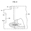
Fig. 3 is a partially sectioned plan view showing a coupling portion between a support bracket and a guide base of the support base; -
Fig. 4 is an enlarged plan view showing a movable body of the support mechanism for the temples; -
Fig. 5 is an enlarged plan view showing a movable body of the support mechanism for the temples; and -
Fig. 6 is a partially sectioned side view when the temples are being mounted on a loom frame by way of the support mechanism for the temples according to an embodiment of the present invention. -
Figs. 1 to 6 illustrate asupport mechanism 10 fortemple 2 and 2' according to an embodiment of the present invention. Thesupport mechanism 10 for thetemples 2 and 2' is installed in a pile fabric loom 1 of fabric moving type that produces awoven fabric 5 having a pile construction through beating while a pair of left andright temples 2 and 2' are moved in a front-rear direction of warps 3 (or woven fabric 5), that is, in a front-rear direction of the pile fabric loom 1 in a cycle of several picks during pile weaving. - Referring to
Fig. 1 , thesupport mechanism 10 for thetemples 2 and 2' includes a plurality ofsupport bases 7, the number of which is four in an illustrated example, fourmovable bodies 8, and aslide bar 9. Thesupport bases 7 are provided on astay 17 at an interval in a weaving-width direction. Thestay 17 couples a pair of left and right loomframes 6 and 6' together. Themovable bodies 8 are respectively supported by the support bases 7, and are movable in the front-rear direction of the warps 3 (or woven fabric 5). Theslide bar 9 is mounted onto upper end surfaces of themovable bodies 8 so as to bridge over themovable bodies 8 in the weaving-width direction, and supports the pair of left andright temples 2 and 2' so that positions of thetemples 2 and 2' are adjustable in the weaving-width direction. - The pair of left and
right temples 2 and 2' are mounted totemple brackets 25 and 25' near a cloth fell of the producedwoven fabric 5, respectively at positions on both sides of the wovenfabric 5 to apply a tension to thewoven fabric 5 in the width-increasing direction. Positions of thetemple brackets 25 and 25' in a height direction are adjustable. Thetemple brackets 25 and 25' are mounted such that head portions of the pair of left andright temples 2 and 2' to be mounted face each other above theslide bar 9 extending in parallel to the weaving-width direction, and that positions of thetemples 2 and 2' are adjustable in the weaving-width direction (or in the extending direction of the slide bar 9). - In addition, a
guide bar 55 is provided in an area between the pair of left andright temples 2 and 2' in the weaving-width direction. Theguide bar 55 extends in the weaving-width direction, and supports the producedwoven fabric 5 from the lower side thereof at a position between the pair of left andright temples 2 and 2'. Theguide bar 55 is mounted above an upper surface of theslide bar 9 with a plurality ofguide bar holders 56 interposed therebetween. Theguide bar holders 56 are arranged at an interval in an area between the left andright temple brackets 25 and 25' in the weaving-width direction, so that a position of theguide bar 55 is adjustable in the weaving-width direction. - Referring to
Fig. 2 , each of thesupport bases 7 mainly includes a pair of left andright support brackets guide base 19 mounted between thesupport brackets plates support brackets guide base 19. In thesupport base 7, lower end surfaces of theguide plates guide base 19 have a pair of left and right lower rolling guide faces 12a and 12b. The upper rolling guide faces 11a and 11b, and the lower rolling guide faces 12a and 12b extend in the front-rear direction of the warps 3 and face each other. - The
guide plates guide plates support brackets movable body 8. Remaining half portions of theguide plates support brackets support brackets screws 26. The lower end surfaces of theguide plates support brackets - The left and right lower rolling guide faces 12a and 12b are defined by the
guide base 19. - Referring to
Figs. 2 and3 , theguide base 19, which is a single plate member, has notches partially on outer surfaces thereof. The notches extend in a width direction of the guide base 19 (a direction orthogonal to the weaving-width direction) at positions in an area inside both ends of theguide base 19 in a longitudinal direction (weaving-width direction), to provide seats (not shown) for thesupport brackets guide base 19 has a penetrating, substantially rectangular hole at a center portion in the longitudinal direction of theguide base 19. The rectangular hole extends in the width direction of the guide base 19 (that is, in the direction orthogonal to the weaving-width direction). The lower rolling guide faces 12a and 12b are provided on both left and right sides of the rectangular hole toward both ends in the longitudinal direction (that is, weaving-width direction). - The rectangular hole has a pair of guide faces 22a and 22b extending in the direction orthogonal to the weaving-width direction, and a regulation surface (not shown) to regulate movement of a slide stopper 21 (described later). The regulation surface is continuously formed with the guide faces 22a and 22b and extends in a direction orthogonal to the guide faces 22a and 22b. Note that the rectangular hole serves as a movement regulation hole 22 that regulates a motion direction of the slide stopper 21 (described later) to the front-rear direction of the warps 3. Alternatively, a groove having the left and right guide faces 22a and 22b may be provided instead of the movement regulation hole 22.
- The
support brackets guide base 19. The upper end surfaces are parallel to the mounting surface of thebase 27. The upper end surface of theguide base 19, which is a plate member, is arranged to be in contact with the step portions provided at the lower portions of thesupport brackets - The
guide base 19 is clamped and fixed to thesupport bracket 18b with a mountingbolt 30 that is screwed from the seat (not shown) of theguide base 19 to thesupport bracket 18b, and a mountingbolt 31 that is screwed from a hollow portion provided at the lower portion of thesupport bracket 18b to theguide base 19. Theguide base 19 is clamped and fixed to thesupport bracket 18a similarly. - Although the detail will be described later, the
guide base 19 defining the lower rolling guide faces 12a and 12b at the upper end surface thereof, and theguide plates movable body 8. Hence, any of theguide base 19, theguide plates support brackets guide base 19, and theguide plates movable body 8 at least during pile formation. - The
guide base 19, which is a plate member, has a constant thickness with upper and lower end surfaces thereof being highly accurately parallel to each other. Also, mounting surfaces of the step portions provided at the lower portions of thesupport brackets guide plates guide base 19 and theguide plates support brackets guide base 19, and the upper rolling guide faces 11a and 11b defined by the lower end surfaces of theguide plates -
Passages 28 are respectively provided in a section including thesupport bracket 18a and a corresponding part of theguide base 19 and in a section including thesupport bracket 18b and another corresponding part of theguide base 19, in a liquid-tight state and communicate with each other in each section while theguide base 19 is clamped and fixed to thesupport brackets Nipples 29 being connected to thepassages 28 are provided at outer lateral portions of thesupport brackets nipples 29 are respectively connected to thepassages 28. An operator supplies grease to thenipples 29 by using a grease pump (not shown) if necessary. The grease is then supplied to turningwheels grease supply holes grease supply holes wheels 14a to 14d at themovable body 8. The supplied grease reduces a frictional resistance between rotating portions of the fourturning wheels 14a to 14d and corresponding sliding portions, and a frictional resistance betweenhead portions 24 defining regulation members (described later) and vertical guide faces 23a and 23b serving as sliding surfaces, thereby reducing occurrence of wear. - The
movable body 8 is mounted on the lower rolling guide faces 12a and 12b of thesupport base 7 having the above-described configuration. Referring toFigs. 4 and5 , themovable body 8, which is a substantially block-like member, has anengagement portion 8a, a mountingportion 8b, and fourturning wheels 14a to 14d. Theengagement portion 8a is a rectangular groove formed at the upper portion of themovable body 8 and extending in a direction orthogonal to a moving direction (described later), that is, in the weaving-width direction, for the slide bar 9 (described later). The mountingportion 8b is cut along the weaving-width direction for apush block 51. The fourturning wheels 14a to 14d are provided at both sides of themovable body 8 rotatably about the moving direction, withspindles wheels 14a to 14d and themovable body 8. On each side, the turning wheels are arranged at positions at a distance in the front-rear direction of the warps 3. Thespindles 13a to 13d respectively havehead portions 24. - In this embodiment, the turning
wheels wheels wheels 14a to 14d are constituted by needle bearings, in which inner sides of the turningwheels 14a to 14d are mounted to thespindles 13a to 13d, and a plurality of needles, which are cylindrical rollers, are arranged in a circumferential direction at positions between outer sides and the inner sides thereof. - Also, a
slide stopper 21 is mounted to a lower end surface of themovable body 8 at a position between thefront turning wheels rear turning wheels screws 52a. Theslide stopper 21 having a substantially T-shaped cross section is a molded product made of a material having a small skid resistance, for example, nylon. When themovable body 8 is mounted on thesupport base 7, that is, when the turningwheels wheels guide base 19, and a lower half portion thereof is arranged so thatlateral portions guide base 19. - The
movable body 8 slides and moves while thelateral portion slide stopper 21 engages with thecorresponding guide face guide base 19. Accordingly, themovable body 8 is prevented from shifting in the weaving-width direction during a reciprocation motion. Theslide stopper 21 can be used for a relatively long time even when theslide stopper 21 is made of resin, because a force in the weaving-width direction causing shifting are distributed into a plurality ofslide stoppers 21. - The regulation units include a fixed-section member 16 (the
guide base 19 having the guide faces 23a and 23b), and a movable-section member 15 (theslide stopper 21 slidable while being in contact with the guide faces 22a and 22b). The fixed-section member 16 is provided at theguide base 19 in an area between the upper rolling guide faces 11a and 11b, and the lower rolling guide faces 12a and 12b, to regulate the reciprocation motion of themovable body 8 only to the front-rear direction of the warps 3. The movable-section member 15 is provided at themovable body 8, and engages with the fixed-section member 16 to regulate the reciprocation motion of themovable body 8 only to the front-rear direction of the warps 3. - When the
support mechanism 10 for thetemples 2 and 2' is to be assembled, first, themovable body 8 is mounted on thesupport base 7 to form an assembled unit, and then, the assembled unit of themovable body 8 and thesupport base 7 is mounted to a predetermined position on thestay 17. - Referring to
Figs. 1 to 3 , in the assembly of thesupport base 7, thesupport brackets guide base 19, and the upper end surface of theguide base 19 is arranged to be in contact with the step portions provided at the lower portions of thesupport brackets guide base 19 is integrally assembled with thesupport brackets bolts 30 screwed from the seats (not shown) of theguide base 19 to thesupport brackets bolts 31 screwed from thesupport brackets guide base 19. - Referring to
Figs. 4 and5 , the fourturning wheels 14a to 14d are rotatably mounted to both sides of themovable body 8 with thespindles 13a to 13d interposed between the turningwheels 14a to 14d and themovable body 8. Also, theslide stopper 21 is fixed to the lower end surface of themovable body 8 withscrews 52a. Thus, themovable body 8 is mounted on theguide base 19 with the lower half portion of theslide stopper 21 accommodated in the movement regulation hole 22, and the fourturning wheels 14a to 14d being in contact with the corresponding lower rolling guide faces 12a and 12b. - The
guide plates support brackets movable body 8, via the mounting screws 26. The upper rolling guide faces 11a and 11b of theguide plates turning wheels 14a to 14d from the upper side, and to face the lower rolling guide faces 12a and 12b. - The
movable body 8 is assembled so as to be mounted on thesupport base 7 to form a unit as described above. Referring toFig. 1 , the plurality ofsupport bases 7 are provided on thestay 17 in the weaving-width direction at a uniform interval as an example. A plurality ofbases 27 are provided on an upper end surface of thestay 17 at positions corresponding to the plurality ofsupport bases 7 and thus are integrally provided. Theintegrated support bases 7 are mounted to thestay 17 while thesupport bases 7 are respectively mounted on thecorresponding bases 27 with mountingbolts 42 that penetrate through thesupport brackets bases 27. The above-describedintegrated support base 7 is removably mounted to thestay 17 without disassembling the components. - The distance between the lower rolling guide faces 12a and 12b, and the upper rolling guide faces 11a and 11b is set so as not to interrupt rolling of the turning
wheels 14a to 14d, in particular, to be slightly larger than an outer diameter of the turningwheels 14a to 14d by about a few tenths mm of the outer diameter thereof. Accordingly, since the turningwheels 14a to 14d come into contact with the lower rolling guide faces 12a and 12b of thesupport base 7 or the upper rolling guide faces 11a and 11b of theguide plates movable body 8 is not lifted markedly in the vertical direction. - In this state, the
slide stopper 21 can slide and move while thelateral portions movable body 8 is assembled to thesupport base 7 movably in the front-rear direction of the warps 3. Also, referring toFig. 6 , covers 43 and 44 having suitable shapes are mounted in front and rear of the fourturning wheels 14a to 14d to prevent cotton fly from adhering on the upper rolling guide faces 11a and 11b and the lower rolling guide faces 12a and 12b. - Referring to
Fig. 1 , the left andright temples 2 and 2' are respectively supported by thetemple brackets 25 and 25' with the temple bases 35 and 35' and the temple guides 36 and 36'.Fig. 6 is a view showing thesupport mechanism 10 for thetemple 2 in a view from the left loomframe 6. This embodiment provides an example of a top-mounted temple in which awoven fabric 5 passes the lower side of thetemple 2. In particular, thetemple 2 mainly includes atemple body 37, atemple bracket 25 that supports thetemple body 37, atemple base 35 functioning as a guide when thewoven fabric 5 is pressed to thetemple body 37 from the lower side, and atemple guide 36. - The
temple body 37, which is a main part of thetemple 2, is a temple of related art in which a plurality of temple rings (not shown) having a plurality of needles embedded in the outer peripheries of the temple rings are placed onto astem 48, and a base end portion and a head portion (both not shown) are placed onto both ends of thestem 48 so as to sandwich the temple rings therebetween. A ring collar (not shown) is interposed between every adjacent temple rings. Rotation axes of the temple rings are provided so as to define an angle increasing toward a weaving end, and to be rotatable relative to thestem 48. Hence, thewoven fabric 5 coming into contact with a lower portion of peripheries of the temple rings can be drawn toward a base end portion as thewoven fabric 5 is advanced toward a take-up side. - A mounting
seat 45 is provided at a base end portion of thetemple body 37. The mountingseat 45 extends in a radial direction, and a tip end thereof is curved. The mountingseat 45 is mounted to atemple holder 46 which is curved and provided at a position corresponding to thetemple body 37 with aclamp screw 47. Thecurved temple holder 46 has through holes (not shown) to which the clamp screws 47 are inserted, in long holes extending in the circumferential direction. Also, a plurality of screw holes 49 are provided at the outer periphery of the mountingseat 45 in the circumferential direction. Accordingly, by selecting insertion positions of the clamp screws 47 to the plurality of screw holes 49, or by adjusting positions of the clamp screws 47 in the long holes, a mounting angle of thetemple body 37 is adjustable around a center axis of thestem 48. Hence, a drawing amount of the wovenfabric 5 is adjustable. - The
slide bar 9 has adovetail groove 32 having an inverted T-shaped cross section and continuously extending in the longitudinal direction. Thetemple bracket 25 is mounted to theslide bar 9 with anut 33 inserted to thedovetail groove 32, and a bolt (not shown) screwed from the upper side and penetrating through aseat 25a, so that the position of thetemple bracket 25 is adjustable in the weaving-width direction. Also, the plurality ofguide bar holders 56 shown inFig. 1 are mounted to theslide bar 9 similarly. Theslide bar 9 is mounted with mountingbolts 50 while engaging with theengagement portions 8a provided at the upper portions of the plurality ofmovable bodies 8 arranged in the weaving-width direction. - When the pile fabric loom 1 is operated, a
weft 4 is inserted to a shed of warps 3, theweft 4 and the warps 3 cross each other again, theweft 4 is beaten with areed 34, and thus, awoven fabric 5 is produced. Thewoven fabric 5, which slightly has weaving crimp in the weaving-width direction, contacts the temple bases 35, and then is wound around thetemple bodies 37. With rotation of the temple rings (not shown), thewoven fabric 5 is pulled back in a direction away from the center of a weaving width against a weaving crimp force. Then wovenfabric 5 is guided by temple guides 36, passes aguide roller 38, and is taken up by a take-up roller (not shown). - Referring to
Fig. 6 , during weaving of a pile construction, arocker arm 40 rocks in the front-rear direction around a spindle (not shown) with a crank, a cam, or a combination of both, in a cycle of several picks. This rocking motion is transmitted to theguide roller 38 provided in a front part of the pile fabric loom 1 and a tension roller (not shown) provided in a rear part of the pile fabric loom 1 for guiding chain warps. When theguide roller 38 and the tension roller are concurrently moved forward and rearward, the warps 3 and thewoven fabric 5 can be moved forward and rearward in synchronization with formation of a pile construction. - The reciprocation motion of the
rocker arm 40 is transmitted to apush arm 41 via anarm 39, to thepush block 51 that is mounted on the mountingportions 8b provided at the upper portions of themovable bodies 8, and then to themovable bodies 8. That is, themovable bodies 8 are configured such that the four, front and rear, left and right turningwheels 14a to 14d are guided with the upper rolling guide faces 11a and 11b, and the lower rolling guide faces 12a and 12b. The rocking motion of therocker arm 40 is converted into the reciprocation motion of themovable bodies 8. Hence, thetemples 2 and 2' and theguide bar 55 are moved forward and rearward in a reciprocating manner during weaving of a pile construction. InFig. 6 , solid lines illustrate a state in which themovable bodies 8 advances maximally. - In a normal condition, since the four
turning wheels 14a to 14d receive a load applied to themovable body 8 by front and rear, left and right sides thereof, the turningwheels 14a to 14d rotate while being in contact with the lower rolling guide faces 12a and 12b. When a force causing themovable body 8 to be lifted acts on themovable body 8, all or part of the fourturning wheels 14a to 14d come into contact with the upper rolling guide faces 11a and 11b, thereby preventing themovable body 8 from being lifted. - During the reciprocation motion of the
movable body 8, theslide stopper 21 slides and moves while thelateral portions movable body 8 so as not to shift in the horizontal direction (weaving-width direction). - The movement regulation of the
movable body 8 in the weaving-width direction, however, is not limited to the above-described embodiment. For example, amovable body 8 may have a projection, and a unit for causing the projection to contact a groove provided in asupport base 7, or a unit for causing the projection to contact a frame member separated from asupport base 7, may be employed for the movement regulation. - Alternatively, during the reciprocation motion of the
movable body 8, the regulation of themovable bodies 8 in the weaving-width direction may be realized by an arrangement in which the guide faces 23a and 23b of thesupport brackets head portions 24 of thespindles 13a to 13d come into contact with each other. With this arrangement, thehead portions 24 serving as the movable-section member 15 slide and move on the guide faces 23a and 23b serving as the fixed-section member 16, to provide a shift-stop action on themovable bodies 8. In this case, theslide stopper 21 and the movement regulation hole 22 are not necessary, however, theslide stopper 21 and the movement regulation hole 22 may be provided with the guide faces 23a and 23b and thehead portions 24. - The upper rolling guide faces 11a and 11b, and the lower rolling guide faces 12a and 12b may be made of three members including the pair of
guide plates guide plates - The present invention in not only applied to a single-width pile fabric loom shown in
Fig. 1 , but also a loom that weaves pile woven fabrics of double or more widths at a time. In such a pile fabric loom,temples 2 and 2' may be provided at weaving ends of each woven fabric. While the foursupport bases 7 are provided in the weaving-width direction, a plurality ofsupport bases 7, the number of which is other than four, may be provided in accordance with a weaving width specification of a loom. - The present invention is applied to a pile fabric loom 1 of fabric moving type. A driving unit for moving a fabric is not limited to a mechanical drive mechanism such as a cam, and may be other mechanisms such as a mechanism driven with an electric motor.
Claims (4)
- A support mechanism (10) for a pair of left and right temples (2, 2') used in a pile fabric loom (1) configured to produce a woven fabric (5) having a pile construction while the temples (2, 2') are moved in a front-rear direction of warps (3) during pile weaving, the support mechanism (10) for the temples (2, 2') comprising:a plurality of support bases (7) provided in a weaving-width direction on a stay (17) configured to couple a pair of left and right loom frames (6, 6');a plurality of movable bodies (8) respectively supported by the support bases (7) and being movable in the front-rear direction of the warps (3);a slide bar (9) mounted onto the movable bodies (8) so as to bridge over the movable bodies (8) in the weaving-width direction, and configured to support the temples (2, 2') so that positions of the temples (2, 2') are adjustable in the weaving-width direction;a pair of left and right upper rolling guide faces (11a, 11b) and a pair of left and right lower rolling guide faces (12a, 12b) provided at each of the support bases (7) so as to extend in the front-rear direction of the warps (3) and to face each other, the upper and lower rolling guide faces (11a, 11b, 12a, 12b) being provided on both sides of the corresponding movable body (8);four turning wheels (14a, 14b, 14c, 14d) provided on both sides of each of the movable bodies (8), the turning wheels being provided at a distance in the front-rear direction of the warps (3) on each side, the turning wheels (14a, 14b, 14c, 14d) being configured to roll and move while being in contact with any of the upper rolling guide faces (11a, 11b) and the lower rolling guide faces (12a, 12b); andregulation units (15, 16) configured to regulate a reciprocation motion of each of the movable bodies (8) only to the front-rear direction of the warps (3) and including a movable-section member (15) provided at each of the movable bodies (8) or to a member moving with each of the movable bodies (8), and a fixed-section member (16) provided at a section provided with the loom frames (6, 6') and engaging with the corresponding movable-section member (15).
- The support mechanism (10) for the temples (2, 2') according to Claim 1, wherein a member for the lower rolling guide faces (12a, 12b) is a guide base (19) which is a single member.
- The support mechanism (10) for the temples (2, 2') according to Claim 1,
wherein each of the support bases (7) includes
a pair of left and right support brackets (18a, 18b) provided on both sides of the corresponding movable body (8),
a guide base (19) mounted to lower portions of the support brackets (18a, 18b), and
a plurality of guide plates (20a, 20b) mounted to upper portions of the support brackets (18a, 18b) in parallel to the guide base (19),
wherein the lower rolling guide faces (12a, 12b) are formed at left and right portions of an upper surface of the guide base (19), and the upper rolling guide faces (11a, 11b) are formed at lower surfaces of the guide plates (20a, 20b), and
wherein the support base (7) with the support brackets (18a, 18b), the guide base (19), and the guide plates (20a, 20b) assembled is removably provided on the stay (17). - The support mechanism (10) for the temples (2, 2') according to Claim 2,
wherein the fixed-section member (16) is the guide base (19) having guide faces (22a, 22b) provided between the upper rolling guide faces (11a, 11b) and the lower rolling guide faces (12a, 12b) and extending in parallel to the front-rear direction of the warps (3), and
wherein the movable-section member (15) is a slide stopper (21) mounted to a lower portion of the movable body (8), the slide stopper (21) being configured to slide and move while the lateral portions (21a, 21b) of the slide stopper (21) engage with the guide faces (22a, 22b).
Applications Claiming Priority (1)
| Application Number | Priority Date | Filing Date | Title |
|---|---|---|---|
| JP2007197255A JP2009030208A (en) | 2007-07-30 | 2007-07-30 | Temple device support device |
Publications (2)
| Publication Number | Publication Date |
|---|---|
| EP2025784A2 true EP2025784A2 (en) | 2009-02-18 |
| EP2025784A3 EP2025784A3 (en) | 2010-12-08 |
Family
ID=39769453
Family Applications (1)
| Application Number | Title | Priority Date | Filing Date |
|---|---|---|---|
| EP08013267A Withdrawn EP2025784A3 (en) | 2007-07-30 | 2008-07-23 | Support mechanism for temple |
Country Status (3)
| Country | Link |
|---|---|
| EP (1) | EP2025784A3 (en) |
| JP (1) | JP2009030208A (en) |
| CN (1) | CN101358401B (en) |
Families Citing this family (2)
| Publication number | Priority date | Publication date | Assignee | Title |
|---|---|---|---|---|
| CN109680392B (en) * | 2019-01-18 | 2024-03-22 | 山东日发纺织机械有限公司 | Temple connecting member |
| CN117758429B (en) * | 2024-02-21 | 2024-05-31 | 海阳科技股份有限公司 | Loom is used in production of density gradual change formula nylon cord fabric |
Citations (1)
| Publication number | Priority date | Publication date | Assignee | Title |
|---|---|---|---|---|
| JPH0790751A (en) | 1993-09-21 | 1995-04-04 | Toyota Autom Loom Works Ltd | Pile forming device in pile loom |
Family Cites Families (5)
| Publication number | Priority date | Publication date | Assignee | Title |
|---|---|---|---|---|
| CS151319B1 (en) * | 1971-05-07 | 1973-10-19 | ||
| JP2000355858A (en) * | 1999-06-16 | 2000-12-26 | Toyota Autom Loom Works Ltd | Fell-support device in loom |
| ITMI20012120A1 (en) * | 2001-10-12 | 2003-04-12 | Promatech Spa | TEMPORAL SUPPORT DEVICE AND REALIVE COVER IN A SPONGE FRAME WITH MOBILE BENCH |
| CN2652965Y (en) * | 2003-10-14 | 2004-11-03 | 王志坚 | Movable edge support mechanism for tyre fabric rapier loom |
| CN2799598Y (en) * | 2005-05-28 | 2006-07-26 | 杭州纺织机械有限公司 | Moving width holding board and width holder mechanism of rapier loom |
-
2007
- 2007-07-30 JP JP2007197255A patent/JP2009030208A/en active Pending
-
2008
- 2008-07-23 EP EP08013267A patent/EP2025784A3/en not_active Withdrawn
- 2008-07-24 CN CN 200810130030 patent/CN101358401B/en active Active
Patent Citations (1)
| Publication number | Priority date | Publication date | Assignee | Title |
|---|---|---|---|---|
| JPH0790751A (en) | 1993-09-21 | 1995-04-04 | Toyota Autom Loom Works Ltd | Pile forming device in pile loom |
Also Published As
| Publication number | Publication date |
|---|---|
| CN101358401A (en) | 2009-02-04 |
| CN101358401B (en) | 2011-05-04 |
| JP2009030208A (en) | 2009-02-12 |
| EP2025784A3 (en) | 2010-12-08 |
Similar Documents
| Publication | Publication Date | Title |
|---|---|---|
| CN101736497B (en) | Warp let-off device for looms with positive warp loosening mechanism | |
| KR100461624B1 (en) | Warp knitting machine with at least a pattern guide bar | |
| CN108457020A (en) | A kind of foot device and embroidery machine for embroidery machine | |
| CN1233297A (en) | A device for controlling warp yarns in weaving leno fabrics on a loom | |
| US4958664A (en) | Air jet loom with a jacquard frame and a variable drawing-in width | |
| CN101429711A (en) | Multi-head double-row quilting and embroidering integrated machine | |
| CN105133174B (en) | Warp knitting and embroidering all-in-one machine | |
| CZ303290B6 (en) | Apparatus for producing gauze fabric | |
| KR20050038568A (en) | Warp weaving machine | |
| KR101188793B1 (en) | Apparatus for feeding yarn of warp knitting machine | |
| CN112777368A (en) | Winding device of warp knitting machine and processing technology applying same | |
| JP4953376B2 (en) | Temple device | |
| JP2009030208A (en) | Temple device support device | |
| CN217078005U (en) | Adjustable embroidery frame of embroidery machine | |
| JP6084508B2 (en) | Fluff generator | |
| CN101194059B (en) | Terry loom | |
| CN117758417B (en) | A variable sheathing mechanism and a loom having the sheathing mechanism | |
| JP3033867B2 (en) | Warp tension adjusting device for loom | |
| CN219410075U (en) | Warp feeding device | |
| CN222821809U (en) | A positioning mechanism for warp knitting machine | |
| CN224227360U (en) | Yarn tension adjusting device of knitting machine | |
| CN114717761B (en) | Adjustable embroidery frame for embroidery machine | |
| CN223357989U (en) | Fabric weft straightening device, weft straightening machine, and pattern straightening machine | |
| CN221052094U (en) | Warping machine adjusting device for spinning | |
| CN119640470B (en) | A weft feeding device |
Legal Events
| Date | Code | Title | Description |
|---|---|---|---|
| PUAI | Public reference made under article 153(3) epc to a published international application that has entered the european phase |
Free format text: ORIGINAL CODE: 0009012 |
|
| AK | Designated contracting states |
Kind code of ref document: A2 Designated state(s): AT BE BG CH CY CZ DE DK EE ES FI FR GB GR HR HU IE IS IT LI LT LU LV MC MT NL NO PL PT RO SE SI SK TR |
|
| AX | Request for extension of the european patent |
Extension state: AL BA MK RS |
|
| PUAL | Search report despatched |
Free format text: ORIGINAL CODE: 0009013 |
|
| AK | Designated contracting states |
Kind code of ref document: A3 Designated state(s): AT BE BG CH CY CZ DE DK EE ES FI FR GB GR HR HU IE IS IT LI LT LU LV MC MT NL NO PL PT RO SE SI SK TR |
|
| AX | Request for extension of the european patent |
Extension state: AL BA MK RS |
|
| AKY | No designation fees paid | ||
| REG | Reference to a national code |
Ref country code: DE Ref legal event code: R108 |
|
| REG | Reference to a national code |
Ref country code: DE Ref legal event code: R108 Effective date: 20110822 |
|
| STAA | Information on the status of an ep patent application or granted ep patent |
Free format text: STATUS: THE APPLICATION IS DEEMED TO BE WITHDRAWN |
|
| 18D | Application deemed to be withdrawn |
Effective date: 20110609 |