EP2025638B1 - A double-acting telescopic hydraulic jack - Google Patents
A double-acting telescopic hydraulic jack Download PDFInfo
- Publication number
- EP2025638B1 EP2025638B1 EP07425492A EP07425492A EP2025638B1 EP 2025638 B1 EP2025638 B1 EP 2025638B1 EP 07425492 A EP07425492 A EP 07425492A EP 07425492 A EP07425492 A EP 07425492A EP 2025638 B1 EP2025638 B1 EP 2025638B1
- Authority
- EP
- European Patent Office
- Prior art keywords
- stem
- lateral wall
- jack
- chamber
- retraction
- Prior art date
- Legal status (The legal status is an assumption and is not a legal conclusion. Google has not performed a legal analysis and makes no representation as to the accuracy of the status listed.)
- Not-in-force
Links
- 239000012530 fluid Substances 0.000 claims abstract description 75
- 238000000034 method Methods 0.000 description 4
- 210000000056 organ Anatomy 0.000 description 3
- 230000009467 reduction Effects 0.000 description 3
- 230000004913 activation Effects 0.000 description 2
- 230000000694 effects Effects 0.000 description 2
- 238000000605 extraction Methods 0.000 description 2
- 230000008569 process Effects 0.000 description 2
- 230000007704 transition Effects 0.000 description 2
- 230000009471 action Effects 0.000 description 1
- 230000006835 compression Effects 0.000 description 1
- 238000007906 compression Methods 0.000 description 1
- 238000002955 isolation Methods 0.000 description 1
- 239000000463 material Substances 0.000 description 1
- 230000035515 penetration Effects 0.000 description 1
- 238000004904 shortening Methods 0.000 description 1
- 238000011144 upstream manufacturing Methods 0.000 description 1
Images

Classifications
-
- B—PERFORMING OPERATIONS; TRANSPORTING
- B66—HOISTING; LIFTING; HAULING
- B66F—HOISTING, LIFTING, HAULING OR PUSHING, NOT OTHERWISE PROVIDED FOR, e.g. DEVICES WHICH APPLY A LIFTING OR PUSHING FORCE DIRECTLY TO THE SURFACE OF A LOAD
- B66F3/00—Devices, e.g. jacks, adapted for uninterrupted lifting of loads
- B66F3/24—Devices, e.g. jacks, adapted for uninterrupted lifting of loads fluid-pressure operated
- B66F3/25—Constructional features
- B66F3/26—Adaptations or arrangements of pistons
- B66F3/28—Adaptations or arrangements of pistons telescopic
-
- F—MECHANICAL ENGINEERING; LIGHTING; HEATING; WEAPONS; BLASTING
- F15—FLUID-PRESSURE ACTUATORS; HYDRAULICS OR PNEUMATICS IN GENERAL
- F15B—SYSTEMS ACTING BY MEANS OF FLUIDS IN GENERAL; FLUID-PRESSURE ACTUATORS, e.g. SERVOMOTORS; DETAILS OF FLUID-PRESSURE SYSTEMS, NOT OTHERWISE PROVIDED FOR
- F15B15/00—Fluid-actuated devices for displacing a member from one position to another; Gearing associated therewith
- F15B15/08—Characterised by the construction of the motor unit
- F15B15/14—Characterised by the construction of the motor unit of the straight-cylinder type
- F15B15/16—Characterised by the construction of the motor unit of the straight-cylinder type of the telescopic type
Definitions
- the invention relates to a double-acting telescopic hydraulic jack.
- a double-acting telescopic hydraulic jack is for example disclosed in EP-A-0 016 921 .
- the present invention particularly relates to a double-acting hydraulic jack in which the extension and retraction of the telescopic stems occurs sequentially and not contemporaneously.
- Prior-art telescopic jacks are constituted by at least two stems and a body which are cylindrical and coaxial and have different diameters, in which the first stem exhibits a smaller diameter than the second stem and the second stem has a smaller diameter than the body.
- the first stem is slidable internally of the second stem and the second stem is slidable internally of the body.
- Telescopic hydraulic jacks actuate a reciprocal sliding between the stems and with the cylinder by means of a pressurised operating fluid which, acting in chambers for extending each stem, extends the first stem with respect to the second and the second stem with respect to the body.
- Double-acting telescopic hydraulic jacks use a pressurised operating fluid which acts in retraction chambers of each stem in order to actuate the retraction of the first stem into the second stem and of the second stem into the body.
- These chambers both the extension chamber and the retraction chamber, are usually made in portions of lateral surfaces, between the first and the second stem and between the second stem and the body, and always face one another independently of the operative configuration of the jack.
- the chambers increase or reduce their volumes during the action of the operating fluid, in order to extend or retract the stems.
- Double-effect telescopic hydraulic jacks are also known in which the distributor organ, i.e. the organ commanding the introduction and extraction of the operating fluid, is located at the free end of the first cylindrical stem, i.e. the stem having the smaller diameter.
- the fluid connection between the distributor organ and the extension chamber of the second stem i.e. the larger-diameter stem, is usually realised by a telescopic cylindrical cable which develops from the distribution up to the bottom of the body (where the outlet chamber commanding the outlet of the second stem is situated).
- the telescopic cylinder is constituted by an internal cavity which longitudinally crosses the second cylindrical stem and by a hollow cylinder, solidly constrained to the first stem and therefore also to the distributor, which engages slidably in the cylindrical cavity of the second stem.
- the operating fluid commanding the extension chamber of the second stem is always in fluid communication with the chamber.
- the distributor sends pressurised fluid through the above-mentioned telescopic cylinder to the extension chamber of the second stem located at the bottom of the body. As the extension chamber fills with pressurised fluid the second stem exits from the body.
- the distributor sends pressurised fluid into the extension chamber of the first stem which, as it fills with pressurised fluid, causes the first stem to extend.
- the distributor sends pressurised fluid into the retraction chamber of the second stem.
- the extension chamber of the second stem is opened, i.e. it is placed in fluid communication with a tank.
- the distributor sends pressurised fluid into the retraction chamber of the stem.
- the extension chamber of the first stem is connected to the discharge in order to allow the stem to retract.
- the second stem would retract spontaneously and uncontrolledly into the body due to the effect of the weight force or due to the effect of a load applied on the free end of the jack.
- the force contrasting the sliding of the hollow cylinder becomes so strong, due to the compression of the operating fluid in the extension chamber of the second stem, that the first stem is no longer able to retract into the second stem.
- the prior-art jacks in which the retraction of the telescopic stems occurs sequentially and not contemporaneously, and in which therefore the jacks do not include proportional discharge valves (i.e. discharge valves which partialise the discharge of the operating fluid), the second stem is retracted before the first stem and only on full retraction of the second stem is the extension chamber of the second stem placed in communication with the discharge in order to enable the first stem to retract.
- proportional discharge valves i.e. discharge valves which partialise the discharge of the operating fluid
- the second stem slides internally of the body until it strikes against the bottom thereof.
- the distributor is activated to discharge the extension chamber of the second stem and at the same time sends oil to the retraction chamber of the second stem.
- the distributor balances the oil coming from the extension chamber of the first stem with the oil sent to the retraction chamber of the first stem.
- the overpressure generates a partial exit of the second stem from a position at the bottom of the body and a raised position with respect thereto.
- the jack instead of having a perfectly closed jack with the section pack-aligned, the jack exhibits the second stem and the first stem thereof partially extended from the body.
- the operator can activate a discharge valve if the discharge valve is included in the standard configuration of the jack.
- the main technical task of the present invention is to provide a double-acting telescopic hydraulic jack which is free of the above-described drawbacks.
- a particular aim of the present invention is to provide a double-acting telescopic hydraulic jack which enables a correct retraction of the smaller-diameter stem independently of the retraction sequence of the stems.
- a further aim of the present invention is to provide a double-acting telescopic hydraulic jack which can resolve the problem of misalignment without having to resort to accessory discharge valves.
- 1 denote in its entirety the double-acting telescopic hydraulic jack of the present invention.
- the jack 1 in the preferred embodiment, comprises a first cylindrical stem 2, a second cylindrical stem 3 and a cylindrical body 4.
- the first stem 2 is slidable internally of the second stem 3 and the second stem is slidable internally of the body 4.
- the number of telescopic stems can, in alternative embodiments which are not illustrated, be greater than two.
- the first stem 2 exhibits a smaller diameter than the diameter of the second stem 3 which in turn exhibits a smaller diameter than that of the body 4, such that the first stem 2 is translatable internally of the second stem 3 and the second stem 3 is translatable internally of the body 4.
- the jack 1 comprises activation chambers, in particular an extension chamber 5 and a retraction chamber 6 for the first stem 2, an extension chamber 7 and a retraction chamber 8 for the second stem 3, for actuating a controlled sliding of the first stem 2 with respect to the second stem 3 and of the second stem 3 with respect to the body 4.
- the first stem 2 and the second stem 3 retract into their seatings, shortening the jack 1 ( figure 1 ).
- the jack 1 comprises a distributor 9 which is solidly constrained to the free end 2a of the first stem, i.e. the opposite end to the end which engages slidably in the second stem 3.
- the distributor 9 comprises three valves 10 (schematically represented in the accompanying figures of the drawings) which selectively set the activation chambers in fluid communication with a fluid source (not illustrated) and a reserve tank (not illustrated).
- the distributor 9 by sending pressurised fluid into the extension chamber 5 of the first stem 2 causes the first stem 2 to extend, and similarly by sending pressurised fluid into the extension chamber 7 of the second stem 3 causes the second stem 3 to extend.
- the extension chamber 5 of the first stem 2 when the extension chamber 5 of the first stem 2 is placed in discharge mode, the first stem 2 retracts into the second stem 3, while when the extension chamber 7 of the second stem 3 is placed in discharge mode the second stem 3 retracts into the body 4.
- extension chambers 5, 7 of the first stem 2 and the second stem 3 are never contemporaneously set in fluid communication with the discharge.
- the jack 1 of the present invention provides for sequential retraction of the stems, i.e. it is of a type in which the first stem 2 and the second stem 3 never retract contemporaneously.
- first stem 2 and the second stem 3 comprise a respective external lateral wall 11, 12 and a respective internal lateral wall 13, 14 which are coaxial to one another.
- the internal lateral walls 13, 14 are of a smaller diameter than the corresponding external lateral walls 11, 12.
- Respective cavities are defined between corresponding internal lateral walls and external lateral walls.
- the external lateral wall 11 of the first stem 2 is slidably inserted between the external lateral wall 12 and the internal lateral wall 14 of the second stem 3.
- the first stem 2 is guided internally of the second stem 3. Further, the internal lateral wall 13 of the first stem 2 is slidably coupled to the internal lateral wall 14 of the second stem 3.
- the space between the external lateral wall 11 of the first stem 2 and the external lateral wall 12 of the second stem 3 defines a chamber which is closed on one side thereof by a portion of bottom 11a of the external lateral wall 11 of the first stem 2 and on the other side thereof by a front portion 12b of the external lateral wall 12 of the second stem 3.
- the closed and sealed chamber defines the retraction chamber 6 of the first stem 2.
- seal rings (not illustrated) which act at the bottom portion 11a of the external lateral wall 11 of the first stem 2 and the front portion 12b of the external lateral wall 12 of the second stem 3.
- the retraction chamber 8 of the second stem 3 is defined between the bottom portion 12a of the external lateral wall 12 of the second stem 3 and a frontal portion 4a of the body 4.
- both the retraction chambers 6, 8 are connected to the same valve of the distributor 9.
- the extension chamber 7 of the second stem 3 is defined between the bottom portion 12a of the external lateral wall 12 of the second stem 3 and a bottom portion 4b of the body 4.
- the conduit 15 is constituted by the internal lateral wall 13 of the first stem 2 and the internal lateral wall 14 of the second stem 3, as can be seen in figures 2 and 3 .
- the conduit 15 is realised by the internal surface of the above-cited walls and reduces its volume according to the degree of retraction of the first stem 2 internally of the second stem 3.
- the conduit 15 has a variable length according to the degree of extraction or retraction of the first stem 2 and the second stem 3.
- the external lateral wall 11 of the first stem 3 comprises an opening 16, located in proximity of the distributor 9, for connecting the closed chamber with the external atmosphere, the closed chamber being created between the external lateral wall 11 and the internal lateral wall 13 of he first stem 2 upstream, i.e. at the distributor end 9, of a frontal portion 14a of the internal lateral wall 14 of the second stem ( figures 2 and 3 ).
- the jack 1 advantageously comprises a compensation chamber 17 located in fluid communication with the conduit 15 for the passage of pressurised fluid and having a variable volume according to the relative position between the first stem 1 and the second stem 3
- the pressurised fluid contained in the conduit 15 fills the compensation chamber 17, enabling a correct retraction of the first stem 2.
- the extension chamber 7 of the second stem 3 is not placed in fluid communication with the reserve tank, in order to prevent uncontrolled retraction of the second stem 3.
- the pressurised fluid in the extension chamber 7 of the second stem 3 and therefore in the conduit 15 thus has no way of exiting from the jack 1.
- the compensation chamber 17 is active between the first stem 2 and the second stem 3 and faces the operating fluid passage conduit 15.
- the compensation chamber 17 exhibits a smallest volume thereof when the first stem 2 is completely extracted from the second stem 3 and exhibits a maximum volume when the first stem 2 is completely retracted into the second stem 3. Therefore, by increasing the degree of the penetration of the first stem 2 into the second stem 3, and particularly the internal lateral wall 13 of the first stem 2 into the internal lateral wall 14 of the second stem 3, the volume of the compensation chamber 17 increases such that the first stem 2 can retract into the second stem 3 without the outlet chamber 7 of the second stem 3 being put into discharge mode. This increase in volume is directly proportional to the pressure increase which would be generated in the conduit 15 in the absence of the compensation chamber 17.
- the compensation chamber 17 is comprised between a bottom portion 13a of the internal lateral wall 13 of the first stem 2 and the frontal portion 14a of the internal lateral wall 14 of the second stem 3 and develops between the internal lateral wall 13 of the first stem 2 and the internal lateral wall 14 of the second stem 3, such as to increase or reduce the volume thereof according to the retraction of the first stem 2 into the second stem 3.
- the compensation chamber 17 comprises an opening 18 located on the internal lateral wall 13 of the first stem 2, such as to guarantee the necessary fluid communication between the compensation chamber 17 and the operating fluid passage conduit 15.
- the opening 18 is located in the immediate vicinity of the bottom portion 13a of the internal lateral wall 13 of the first stem 2, such as to guarantee the correct fluid connection independently of the relative positions of the first stem 2 and the second stem 3.
- pressurised fluid is sent into the outlet chamber 5, 7 of the first stem 2 or the second stem 3 and the non-pressurised extension chamber 5, 7 is isolated from both the fluid source and the reserve tank.
- the other stem 3 or 2 is also extended.
- the extension chamber 5 of the first stem 2 is isolated from both the pressurised fluid source and the reserve tank.
- the outlet chamber 7 of the second stem 3 is then set in fluid communication with the reserve tank and pressurised fluid is sent into the retraction chamber 8 of the second stem 3.
- the first stem 2 then begins to retract.
- extension chamber 5 of the first stem 2 is set in fluid communication with the reserve tank, and the extension chamber 7 of the second stem 3 is isolated and pressurised fluid is sent into the retraction chamber 6 of the first stem 2.
- the first stem begins to retract and, as described above, the conduit 15 shortens due to the fact that the internal lateral wall 13 of the first stem 2 slides along the internal lateral wall 14 of the second stem 3.
- the fluid in the conduit 15 then begins to compress, as the extension chamber 7 of the second stem 3 is kept in isolation both from the reserve tank and from the pressure source.
- This process i.e. the increase of volume of the compensation chamber 17 and the reduction of volume internally of the conduit 15, continue up until the first stem 2 is completely retracted into the second stem 3.
- the second retraction process of the jack 1 comprises first the retraction of the first stem 2 internally of the second stem 3, followed by the retraction of the second stem 3 internally of the body 4.
Landscapes
- Engineering & Computer Science (AREA)
- Mechanical Engineering (AREA)
- Fluid Mechanics (AREA)
- Geology (AREA)
- Structural Engineering (AREA)
- Physics & Mathematics (AREA)
- Life Sciences & Earth Sciences (AREA)
- General Engineering & Computer Science (AREA)
- Fluid-Damping Devices (AREA)
- Infusion, Injection, And Reservoir Apparatuses (AREA)
- Vehicle Body Suspensions (AREA)
- Forklifts And Lifting Vehicles (AREA)
- Actuator (AREA)
Abstract
Description
- The invention relates to a double-acting telescopic hydraulic jack. Such a jack is for example disclosed in
EP-A-0 016 921 . - The present invention particularly relates to a double-acting hydraulic jack in which the extension and retraction of the telescopic stems occurs sequentially and not contemporaneously.
- Prior-art telescopic jacks are constituted by at least two stems and a body which are cylindrical and coaxial and have different diameters, in which the first stem exhibits a smaller diameter than the second stem and the second stem has a smaller diameter than the body.
- The first stem is slidable internally of the second stem and the second stem is slidable internally of the body.
- Telescopic hydraulic jacks actuate a reciprocal sliding between the stems and with the cylinder by means of a pressurised operating fluid which, acting in chambers for extending each stem, extends the first stem with respect to the second and the second stem with respect to the body.
- Double-acting telescopic hydraulic jacks use a pressurised operating fluid which acts in retraction chambers of each stem in order to actuate the retraction of the first stem into the second stem and of the second stem into the body.
- These chambers, both the extension chamber and the retraction chamber, are usually made in portions of lateral surfaces, between the first and the second stem and between the second stem and the body, and always face one another independently of the operative configuration of the jack.
- The chambers increase or reduce their volumes during the action of the operating fluid, in order to extend or retract the stems.
- Double-effect telescopic hydraulic jacks are also known in which the distributor organ, i.e. the organ commanding the introduction and extraction of the operating fluid, is located at the free end of the first cylindrical stem, i.e. the stem having the smaller diameter.
- The fluid connection between the distributor organ and the extension chamber of the second stem, i.e. the larger-diameter stem, is usually realised by a telescopic cylindrical cable which develops from the distribution up to the bottom of the body (where the outlet chamber commanding the outlet of the second stem is situated).
- The telescopic cylinder is constituted by an internal cavity which longitudinally crosses the second cylindrical stem and by a hollow cylinder, solidly constrained to the first stem and therefore also to the distributor, which engages slidably in the cylindrical cavity of the second stem.
- In this way, independently of the relative position between the first and second stems, the operating fluid commanding the extension chamber of the second stem is always in fluid communication with the chamber.
- Therefore, in order to extend the second stem (with the larger diameter) the distributor sends pressurised fluid through the above-mentioned telescopic cylinder to the extension chamber of the second stem located at the bottom of the body. As the extension chamber fills with pressurised fluid the second stem exits from the body.
- To extend the first stem with respect to the second stem, the distributor sends pressurised fluid into the extension chamber of the first stem which, as it fills with pressurised fluid, causes the first stem to extend.
- In order to retract the second stem, the distributor sends pressurised fluid into the retraction chamber of the second stem. At the same time, the extension chamber of the second stem is opened, i.e. it is placed in fluid communication with a tank.
- In this way, the pressurised fluid sent by the distributor pushes the second stem internally of the body and the fluid in the extension chamber of the second stem exits from the chamber.
- Similarly, to retract the first stem into the second stem the distributor sends pressurised fluid into the retraction chamber of the stem. At the same time the extension chamber of the first stem is connected to the discharge in order to allow the stem to retract.
- In many applications in which prior-art jacks are used, it is of fundamental importance that during the retraction of the first stem (with the smaller diameter), the extension chamber of the second stem is not set in fluid connection with the discharge.
- If this were to happen, the second stem would retract spontaneously and uncontrolledly into the body due to the effect of the weight force or due to the effect of a load applied on the free end of the jack.
- Let us consider a case in which the jack is used for raising and lowering a load.
- During the lowering, with the aim of retracting the first stem, if the extension chamber of the second stem were placed in communication with the discharge, the second stem would sharply and uncontrolledly retract internally of the body, with very dangerous consequences.
- However, during the retraction of the first stem into the second, a part of the hollow cylinder, belonging to the telescopic cylinder which sets the distributor in fluid communication with the extension chamber of the second stem, retracts internally of the cylindrical cavity which crosses the second stem.
- Consequently, the pressurised fluid filling the telescopic cylinder and the extension chamber of the second stem is further compressed, obstructing the sliding of the hollow cylinder internally of the cavity of the second stem.
- At a certain point, the force contrasting the sliding of the hollow cylinder becomes so strong, due to the compression of the operating fluid in the extension chamber of the second stem, that the first stem is no longer able to retract into the second stem.
- To obviate this drawback, the prior-art jacks in which the retraction of the telescopic stems occurs sequentially and not contemporaneously, and in which therefore the jacks do not include proportional discharge valves (i.e. discharge valves which partialise the discharge of the operating fluid), the second stem is retracted before the first stem and only on full retraction of the second stem is the extension chamber of the second stem placed in communication with the discharge in order to enable the first stem to retract.
- During the retraction of the stems, in a case where the operator performs the retraction first of the second stem and then of the first stem, there is the disadvantage of misalignment of the jack on closure.
- During the first retraction stage the second stem slides internally of the body until it strikes against the bottom thereof.
- During this transition the distributor is activated to discharge the extension chamber of the second stem and at the same time sends oil to the retraction chamber of the second stem.
- Thereafter the first stem is retracted into the second stem, and this time the extension chamber of the first stem is placed in connection with the discharge.
- The distributor balances the oil coming from the extension chamber of the first stem with the oil sent to the retraction chamber of the first stem.
- During this transition the volume of material of the first stem, which retracts into the second stem, leads to a decompensation in the balancing performed by the distributor, generating an overpressure internally of the jack.
- The overpressure generates a partial exit of the second stem from a position at the bottom of the body and a raised position with respect thereto.
- Thus, instead of having a perfectly closed jack with the section pack-aligned, the jack exhibits the second stem and the first stem thereof partially extended from the body.
- To obviate this drawback of misalignment the operator can activate a discharge valve if the discharge valve is included in the standard configuration of the jack.
- The main technical task of the present invention is to provide a double-acting telescopic hydraulic jack which is free of the above-described drawbacks.
- A particular aim of the present invention is to provide a double-acting telescopic hydraulic jack which enables a correct retraction of the smaller-diameter stem independently of the retraction sequence of the stems.
- A further aim of the present invention is to provide a double-acting telescopic hydraulic jack which can resolve the problem of misalignment without having to resort to accessory discharge valves.
- The technical aim and the specified objective are substantially attained by a double-acting telescopic hydraulic jack comprising the technical characteristics described in one or more of the appended claims.
- Further characteristics and advantages of the present invention will better emerge from the non-limiting description which follows of a preferred but not exclusive embodiment of the double-acting telescopic hydraulic jack of the invention, as illustrated in the accompanying figures of the drawings, in which:
-
figure 1 is a schematic view of a double-acting telescopic hydraulic jack of the present invention in a first operating configuration; -
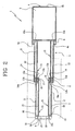
figure 2 is a schematic view of the jack offigure 1 in a second operative configuration; and -
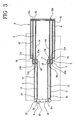
figure 3 is a schematic view of the jack offigure 1 in a third operative configuration. - With reference to the figures of the drawings, 1 denote in its entirety the double-acting telescopic hydraulic jack of the present invention.
- The
jack 1, in the preferred embodiment, comprises a firstcylindrical stem 2, a secondcylindrical stem 3 and acylindrical body 4. - The
first stem 2 is slidable internally of thesecond stem 3 and the second stem is slidable internally of thebody 4. Note that the number of telescopic stems can, in alternative embodiments which are not illustrated, be greater than two. - As illustrated in the accompanying figures of the drawings, in which the
jack 1 has been schematised in a section view along the main development axis of the jack, thefirst stem 2 exhibits a smaller diameter than the diameter of thesecond stem 3 which in turn exhibits a smaller diameter than that of thebody 4, such that thefirst stem 2 is translatable internally of thesecond stem 3 and thesecond stem 3 is translatable internally of thebody 4. - The
jack 1 comprises activation chambers, in particular anextension chamber 5 and aretraction chamber 6 for thefirst stem 2, an extension chamber 7 and aretraction chamber 8 for thesecond stem 3, for actuating a controlled sliding of thefirst stem 2 with respect to thesecond stem 3 and of thesecond stem 3 with respect to thebody 4. - By sending an operating fluid, preferably oil, under pressure into the
extension chambers 5, 7, thefirst stem 2 and thesecond stem 3 exit from the respective seatings, causing thejack 1 to extend (figure 2 ). - Similarly, by sending a pressurised operating fluid into the
retraction chambers first stem 2 and thesecond stem 3 retract into their seatings, shortening the jack 1 (figure 1 ). - The
jack 1 comprises adistributor 9 which is solidly constrained to thefree end 2a of the first stem, i.e. the opposite end to the end which engages slidably in thesecond stem 3. - The
distributor 9 comprises three valves 10 (schematically represented in the accompanying figures of the drawings) which selectively set the activation chambers in fluid communication with a fluid source (not illustrated) and a reserve tank (not illustrated). - In particular, the
distributor 9, by sending pressurised fluid into theextension chamber 5 of thefirst stem 2 causes thefirst stem 2 to extend, and similarly by sending pressurised fluid into the extension chamber 7 of thesecond stem 3 causes thesecond stem 3 to extend. - When the
distributor 9 sends pressurised fluid into theretracting chambers extension chambers 5, 7 in fluid communication with the reserve tank (discharge), a stem is retracted. - In particular, when the
extension chamber 5 of thefirst stem 2 is placed in discharge mode, thefirst stem 2 retracts into thesecond stem 3, while when the extension chamber 7 of thesecond stem 3 is placed in discharge mode thesecond stem 3 retracts into thebody 4. - It is to be stressed that the
extension chambers 5, 7 of thefirst stem 2 and thesecond stem 3 are never contemporaneously set in fluid communication with the discharge. - Note that the
jack 1 of the present invention provides for sequential retraction of the stems, i.e. it is of a type in which thefirst stem 2 and thesecond stem 3 never retract contemporaneously. - As is schematically illustrated in the accompanying figures of the drawings, the
first stem 2 and thesecond stem 3 comprise a respective externallateral wall lateral wall lateral walls lateral walls - Respective cavities are defined between corresponding internal lateral walls and external lateral walls.
- The external
lateral wall 11 of thefirst stem 2 is slidably inserted between the externallateral wall 12 and the internallateral wall 14 of thesecond stem 3. - In this way, the
first stem 2 is guided internally of thesecond stem 3. Further, the internallateral wall 13 of thefirst stem 2 is slidably coupled to the internallateral wall 14 of thesecond stem 3. - As illustrated in
figure 3 , the space between the externallateral wall 11 of thefirst stem 2 and the externallateral wall 12 of thesecond stem 3 defines a chamber which is closed on one side thereof by a portion of bottom 11a of the externallateral wall 11 of thefirst stem 2 and on the other side thereof by afront portion 12b of the externallateral wall 12 of thesecond stem 3. - The closed and sealed chamber defines the
retraction chamber 6 of thefirst stem 2. - The seal of this chamber is guaranteed by seal rings (not illustrated) which act at the
bottom portion 11a of the externallateral wall 11 of thefirst stem 2 and thefront portion 12b of the externallateral wall 12 of thesecond stem 3. - The fluid connection between the
retraction chamber 6 of thefirst stem 2 and the distributor 9 (schematically illustrated in the figure by a broken line) is guaranteed by small tubes (not illustrated) which develop internally of thejack 1. - The
retraction chamber 8 of thesecond stem 3 is defined between thebottom portion 12a of the externallateral wall 12 of thesecond stem 3 and afrontal portion 4a of thebody 4. - In this case too the fluid connection between the
retraction chamber 8 of thesecond stem 3 and the distributor 9 (schematically illustrated in the figure by a broken line) is guaranteed by tubes (not illustrated) which develop internally of thejack 1. - Note that both the
retraction chambers distributor 9. - The extension chamber 7 of the
second stem 3 is defined between thebottom portion 12a of the externallateral wall 12 of thesecond stem 3 and abottom portion 4b of thebody 4. - In this case, the fluid connection between the distributor and the extension chamber 7 of the
second stem 3 is guaranteed by atelescopic conduit 15 through which the pressurised fluid passes. - The
conduit 15 is constituted by the internallateral wall 13 of thefirst stem 2 and the internallateral wall 14 of thesecond stem 3, as can be seen infigures 2 and3 . In particular, theconduit 15 is realised by the internal surface of the above-cited walls and reduces its volume according to the degree of retraction of thefirst stem 2 internally of thesecond stem 3. - Since, as mentioned above, the internal
lateral wall 13 of thefirst stem 2 is slidably coupled to the internallateral wall 14 of thesecond stem 3, theconduit 15 has a variable length according to the degree of extraction or retraction of thefirst stem 2 and thesecond stem 3. - The external
lateral wall 11 of thefirst stem 3 comprises anopening 16, located in proximity of thedistributor 9, for connecting the closed chamber with the external atmosphere, the closed chamber being created between the externallateral wall 11 and the internallateral wall 13 of he first stem 2 upstream, i.e. at thedistributor end 9, of afrontal portion 14a of the internallateral wall 14 of the second stem (figures 2 and3 ). - The
jack 1 advantageously comprises acompensation chamber 17 located in fluid communication with theconduit 15 for the passage of pressurised fluid and having a variable volume according to the relative position between thefirst stem 1 and thesecond stem 3 - In this way, during the retraction of the
first stem 2, the pressurised fluid contained in theconduit 15 fills thecompensation chamber 17, enabling a correct retraction of thefirst stem 2. - It is stressed that without the presence of the
compensation chamber 17 thefirst stem 2 would be obstructed in retraction into thesecond stem 3 by the gradually increasing pressure acting on the internallateral wall 13 of thefirst stem 2; without thecompensation chamber 17 there would be the problem of misalignment. - The internal
lateral wall 13 of thefirst stem 2, as it slides along the internallateral wall 14 of thesecond stem 3, reduces the volume of theconduit 15, consequently increasing the pressure of the operating fluid contained therein. - In this configuration, it is to be noted that, as the
jack 1 is of the sequential retraction type (in the above-specified sense), when thefirst stem 2 retracts into thesecond stem 3, the extension chamber 7 of thesecond stem 3 is not placed in fluid communication with the reserve tank, in order to prevent uncontrolled retraction of thesecond stem 3. - The pressurised fluid in the extension chamber 7 of the
second stem 3 and therefore in theconduit 15 thus has no way of exiting from thejack 1. - In particular, in the preferred embodiment, the
compensation chamber 17 is active between thefirst stem 2 and thesecond stem 3 and faces the operatingfluid passage conduit 15. - The
compensation chamber 17 exhibits a smallest volume thereof when thefirst stem 2 is completely extracted from thesecond stem 3 and exhibits a maximum volume when thefirst stem 2 is completely retracted into thesecond stem 3. Therefore, by increasing the degree of the penetration of thefirst stem 2 into thesecond stem 3, and particularly the internallateral wall 13 of thefirst stem 2 into the internallateral wall 14 of thesecond stem 3, the volume of thecompensation chamber 17 increases such that thefirst stem 2 can retract into thesecond stem 3 without the outlet chamber 7 of thesecond stem 3 being put into discharge mode. This increase in volume is directly proportional to the pressure increase which would be generated in theconduit 15 in the absence of thecompensation chamber 17. - As illustrated in the figures of the drawings, the
compensation chamber 17 is comprised between abottom portion 13a of the internallateral wall 13 of thefirst stem 2 and thefrontal portion 14a of the internallateral wall 14 of thesecond stem 3 and develops between the internallateral wall 13 of thefirst stem 2 and the internallateral wall 14 of thesecond stem 3, such as to increase or reduce the volume thereof according to the retraction of thefirst stem 2 into thesecond stem 3. - The
compensation chamber 17 comprises anopening 18 located on the internallateral wall 13 of thefirst stem 2, such as to guarantee the necessary fluid communication between thecompensation chamber 17 and the operatingfluid passage conduit 15. - Note that the
opening 18 is located in the immediate vicinity of thebottom portion 13a of the internallateral wall 13 of thefirst stem 2, such as to guarantee the correct fluid connection independently of the relative positions of thefirst stem 2 and thesecond stem 3. - In use, in order to open, i.e. extend, the
jack 1, pressurised fluid is sent into theoutlet chamber 5, 7 of thefirst stem 2 or thesecond stem 3 and thenon-pressurised extension chamber 5, 7 is isolated from both the fluid source and the reserve tank. - Once the
first stem 2 or thesecond stem 3 is extended, theother stem - To retract the
jack 1, two different procedures can be used. - In the first procedure, the
extension chamber 5 of thefirst stem 2 is isolated from both the pressurised fluid source and the reserve tank. - The outlet chamber 7 of the
second stem 3 is then set in fluid communication with the reserve tank and pressurised fluid is sent into theretraction chamber 8 of thesecond stem 3. - At this point the
second stem 3 retracts into thebody 4. - The
first stem 2 then begins to retract. - In particular, the
extension chamber 5 of thefirst stem 2 is set in fluid communication with the reserve tank, and the extension chamber 7 of thesecond stem 3 is isolated and pressurised fluid is sent into theretraction chamber 6 of thefirst stem 2. - The first stem begins to retract and, as described above, the
conduit 15 shortens due to the fact that the internallateral wall 13 of thefirst stem 2 slides along the internallateral wall 14 of thesecond stem 3. - The fluid in the
conduit 15 then begins to compress, as the extension chamber 7 of thesecond stem 3 is kept in isolation both from the reserve tank and from the pressure source. - The increase of fluid pressure internally of the
conduit 15, which would obstruct the retraction of thefirst stem 2 or would cause the exit of thesecond stem 3 from thebody 4, and the contemporary increase of volume of the compensation chamber 17 (for the above-described reason) determine a flow of operating fluid from theconduit 15 to thecompensation chamber 17, returning the operating fluid pressure in theconduit 15 to the original level. - This process, i.e. the increase of volume of the
compensation chamber 17 and the reduction of volume internally of theconduit 15, continue up until thefirst stem 2 is completely retracted into thesecond stem 3. - It is stressed that the increase of volume of the
compensation chamber 17 is directly proportional to, and preferable coincides with, the reduction of volume of theconduit 15, such that the operating fluid pressure internally of theconduit 15 is kept constant during the retraction of thefirst stem 2. - The second retraction process of the
jack 1 comprises first the retraction of thefirst stem 2 internally of thesecond stem 3, followed by the retraction of thesecond stem 3 internally of thebody 4. - Note that in this case nothing changes regarding the retraction of the
first stem 2 into thesecond stem 3, since an increase in volume of thecompensation chamber 17 continues to correspond to the reduction of volume in theconduit 15.
Claims (12)
- A double-acting telescopic hydraulic jack, preferably a sequential retracting jack, comprising:a first stem (2) which is cylindrical and hollow and has a predetermined diameter, a second stem (3) which is cylindrical and hollow and has a predetermined diameter which is greater than the diameter of the first stem (2), the first stem (2) being slidably inserted in the second stem (3);a hollow cylindrical body (4) having a predetermined diameter which is greater than the diameter of the second stem (3), the second stem (3) being slidably inserted in the body (4);actuating chambers (5, 6, 7, 8) for extension and retraction of the first stem (2) with respect to the second stem (3) and the second stem (3) with respect to the body (4);the first stem (2) defining, in combination with the second stem (3), a telescopic passage conduit (15) for an operating fluid for actuating the chamber (7) for extension of the second stem (3);characterised in that it comprises a compensating chamber (17) set in fluid communication with the conduit (15) for passage of pressurised fluid andhaving a variable volume according to the relative position of the first stem (2) and the second stem (3) in order to receive operating fluid during the retraction of the second stem (3).
- The jack of claim 1, wherein the compensation chamber (17) is active between the first stem (2) and the second stem (3) and faces the conduit (15) for operating fluid passage.
- The jack of claim 1 or 2, wherein the compensation chamber (17) exhibits a minimum volume thereof when the first stem (2) is completely extended with respect to the second stem (3), and exhibits a maximum volume when the first stem (2) is completely retracted in the second stem (3).
- The jack of any one of the preceding claims, comprising a distributor (9) for the operating fluid; the distributor (9) being solidly constrained to a free end (2a) of the first stem (2) and setting a pressurised fluid tank in fluid communication with the actuating chambers (5, 6, 7, 8).
- The jack of any one of the preceding claims, wherein the first stem (2) and the second stem (3) comprise a respective external lateral wall (11, 12) and a respective internal lateral wall (13, 14) which are coaxial to one another, the external lateral wall (11) of the first stem (2) being slidably inserted between the external lateral wall (12) and the internal lateral wall (14) of the second stem (3) and the internal lateral wall (13) of the first stem (2) being slidably coupled to the internal lateral wall (14) of the second stem (3).
- The jack of claim 5, wherein the compensation chamber (17) is comprised between the internal lateral wall (13) of the first stem (2) and the internal lateral wall (14) of the second stem (3) and comprises an opening (18) located on the internal lateral wall (13) of the first stem (2) in order to be in fluid communication with the conduit (15) for operating fluid passage.
- The jack of claim 6, wherein the compensation chamber (17) is defined between a frontal portion (14a) of the internal lateral wall (14) of the second stem (3) and a bottom portion (13a) of the internal lateral wall (13) of the first stem (2), for increasing or reducing a volume thereof according to a retraction of the first stem (2) into the second stem (3).
- The jack of any one of claims from 5 to 7, wherein the chamber (5) for the extension of the first stem (2) is defined between the lateral walls (12, 14) of the first stem (2) and between the bottom portion (11a) of the external lateral wall (11) of the first stem (2) and a bottom portion (12a) of the external lateral wall (12) of the second stem (3).
- The jack of any one of claims from 5 to 8, wherein the chamber (7) for retraction of the first stem (2) is defined between the bottom portion (12a) of the external lateral wall (12) of the second stem (3) and a bottom portion (4b) of the cylindrical body (4).
- The jack of any one of claims from 5 to 9, wherein the chamber (6) for extension of the second stem (3) is defined between the external lateral wall (11) of the first stem (2) and the external lateral wall (12) of the second stem (3) and is closed at one end thereof by a portion of bottom (11a) of the external lateral wall (11) of the first stem (2) and at the other end thereof by a front portion (12b) of the external lateral wall (12) of the second stem (3).
- The jack of any one of claims from 5 to 10, wherein the chamber (8) for retraction of the second stem (3) is defined between a frontal portion (4a) of the cylindrical body (4) and a portion of bottom (12a) of the external lateral wall (12) of the second stem (3).
- The jack of claim 4, wherein the distributor (9) comprises three valves (10), respectively for selectively placing the extension chamber (5) of the first stem (2) with a pressurised fluid source or a reserve tank in fluid communication; for selectively placing the extension chamber (6) of the second stem (3) with a pressurised fluid source or a reserve tank in fluid communication; and for selectively placing the retraction chambers (7, 8) of the first stem (2) and the second stem (3) in fluid communication with a pressurised fluid source or a reserve tank.
Priority Applications (3)
| Application Number | Priority Date | Filing Date | Title |
|---|---|---|---|
| AT07425492T ATE498580T1 (en) | 2007-07-31 | 2007-07-31 | DOUBLE ACTION TELESCOPIC HYDRAULIC JACK |
| EP07425492A EP2025638B1 (en) | 2007-07-31 | 2007-07-31 | A double-acting telescopic hydraulic jack |
| DE602007012537T DE602007012537D1 (en) | 2007-07-31 | 2007-07-31 | Double-acting telescopic hydraulic lift |
Applications Claiming Priority (1)
| Application Number | Priority Date | Filing Date | Title |
|---|---|---|---|
| EP07425492A EP2025638B1 (en) | 2007-07-31 | 2007-07-31 | A double-acting telescopic hydraulic jack |
Publications (2)
| Publication Number | Publication Date |
|---|---|
| EP2025638A1 EP2025638A1 (en) | 2009-02-18 |
| EP2025638B1 true EP2025638B1 (en) | 2011-02-16 |
Family
ID=38740530
Family Applications (1)
| Application Number | Title | Priority Date | Filing Date |
|---|---|---|---|
| EP07425492A Not-in-force EP2025638B1 (en) | 2007-07-31 | 2007-07-31 | A double-acting telescopic hydraulic jack |
Country Status (3)
| Country | Link |
|---|---|
| EP (1) | EP2025638B1 (en) |
| AT (1) | ATE498580T1 (en) |
| DE (1) | DE602007012537D1 (en) |
Family Cites Families (4)
| Publication number | Priority date | Publication date | Assignee | Title |
|---|---|---|---|---|
| DE1107383B (en) * | 1957-05-29 | 1961-05-25 | Rheinstahl Siegener Eisenbahnb | Double-acting, multi-stage telescopic lifting ram |
| DE2104502C3 (en) * | 1971-02-01 | 1973-10-31 | Fa. Heinrich Brauer, 4150 Krefeld | Hydraulic lifting device |
| EP0016921A1 (en) * | 1979-02-05 | 1980-10-15 | Georg Fischer Aktiengesellschaft | Telescopic device |
| DK159289C (en) * | 1987-10-01 | 1991-02-25 | Nisap Maskinfabrik As | HYDRAULIC TELESCOPE DEVICE |
-
2007
- 2007-07-31 AT AT07425492T patent/ATE498580T1/en not_active IP Right Cessation
- 2007-07-31 DE DE602007012537T patent/DE602007012537D1/en active Active
- 2007-07-31 EP EP07425492A patent/EP2025638B1/en not_active Not-in-force
Also Published As
| Publication number | Publication date |
|---|---|
| EP2025638A1 (en) | 2009-02-18 |
| DE602007012537D1 (en) | 2011-03-31 |
| ATE498580T1 (en) | 2011-03-15 |
Similar Documents
| Publication | Publication Date | Title |
|---|---|---|
| US9718655B2 (en) | Loading crane jib | |
| CZ105299A3 (en) | Hydraulically adjustable non-return valve for hydraulic equipment in mining underground operations | |
| US20070068754A1 (en) | Gas-biased hydraulic cylinder | |
| US8910659B2 (en) | Hydraulic valve device | |
| US6736380B2 (en) | Adjustable-length gas spring | |
| CA2587596C (en) | Low impact spot welding cylinder using single or double piston | |
| US7458308B2 (en) | Multistaged telescope boom | |
| EP2025638A1 (en) | A double-acting telescopic hydraulic jack | |
| CA2813980A1 (en) | Telescopic cylinder | |
| EP1270494A1 (en) | Extension device for telescopic booms of hydraulic cranes | |
| PL206052B1 (en) | Unblocked check valve | |
| US11105441B2 (en) | Method of controlling a three-position slide valve | |
| US2883859A (en) | Operating mechanism for a pipe testing machine | |
| EP2452079B1 (en) | Double-acting hydraulic cylinder with integrated gas spring action and method for making the same | |
| JP3204283U (en) | Manual pump | |
| US12173772B2 (en) | Adjustable suspension for a bicycle | |
| DE102019202883A1 (en) | Hydraulic control arrangement and drive unit | |
| KR102384930B1 (en) | The pump of double tube | |
| JP5841015B2 (en) | Impact tool | |
| ES2911311T3 (en) | Method and system for a hydraulic cylinder | |
| KR100489250B1 (en) | Vaccum Gate Valve | |
| CA3125677C (en) | Adjustable suspension for a bicycle | |
| CN103790892B (en) | The single-acting multistage column plug oil hydraulic cylinder that a kind of flexible order is controlled | |
| EP0310022B1 (en) | Hydraulic telescopic device | |
| IT201900009243A1 (en) | Device for the sequential operation of two or more cylinders |
Legal Events
| Date | Code | Title | Description |
|---|---|---|---|
| PUAI | Public reference made under article 153(3) epc to a published international application that has entered the european phase |
Free format text: ORIGINAL CODE: 0009012 |
|
| AK | Designated contracting states |
Kind code of ref document: A1 Designated state(s): AT BE BG CH CY CZ DE DK EE ES FI FR GB GR HU IE IS IT LI LT LU LV MC MT NL PL PT RO SE SI SK TR |
|
| AX | Request for extension of the european patent |
Extension state: AL BA HR MK RS |
|
| 17P | Request for examination filed |
Effective date: 20090611 |
|
| AKX | Designation fees paid |
Designated state(s): AT BE BG CH CY CZ DE DK EE ES FI FR GB GR HU IE IS IT LI LT LU LV MC MT NL PL PT RO SE SI SK TR |
|
| GRAP | Despatch of communication of intention to grant a patent |
Free format text: ORIGINAL CODE: EPIDOSNIGR1 |
|
| GRAS | Grant fee paid |
Free format text: ORIGINAL CODE: EPIDOSNIGR3 |
|
| GRAA | (expected) grant |
Free format text: ORIGINAL CODE: 0009210 |
|
| AK | Designated contracting states |
Kind code of ref document: B1 Designated state(s): AT BE BG CH CY CZ DE DK EE ES FI FR GB GR HU IE IS IT LI LT LU LV MC MT NL PL PT RO SE SI SK TR |
|
| REG | Reference to a national code |
Ref country code: GB Ref legal event code: FG4D |
|
| REG | Reference to a national code |
Ref country code: CH Ref legal event code: EP |
|
| REG | Reference to a national code |
Ref country code: IE Ref legal event code: FG4D |
|
| REF | Corresponds to: |
Ref document number: 602007012537 Country of ref document: DE Date of ref document: 20110331 Kind code of ref document: P |
|
| REG | Reference to a national code |
Ref country code: DE Ref legal event code: R096 Ref document number: 602007012537 Country of ref document: DE Effective date: 20110331 |
|
| REG | Reference to a national code |
Ref country code: NL Ref legal event code: VDEP Effective date: 20110216 |
|
| LTIE | Lt: invalidation of european patent or patent extension |
Effective date: 20110216 |
|
| PG25 | Lapsed in a contracting state [announced via postgrant information from national office to epo] |
Ref country code: LV Free format text: LAPSE BECAUSE OF FAILURE TO SUBMIT A TRANSLATION OF THE DESCRIPTION OR TO PAY THE FEE WITHIN THE PRESCRIBED TIME-LIMIT Effective date: 20110216 Ref country code: LT Free format text: LAPSE BECAUSE OF FAILURE TO SUBMIT A TRANSLATION OF THE DESCRIPTION OR TO PAY THE FEE WITHIN THE PRESCRIBED TIME-LIMIT Effective date: 20110216 Ref country code: ES Free format text: LAPSE BECAUSE OF FAILURE TO SUBMIT A TRANSLATION OF THE DESCRIPTION OR TO PAY THE FEE WITHIN THE PRESCRIBED TIME-LIMIT Effective date: 20110527 Ref country code: GR Free format text: LAPSE BECAUSE OF FAILURE TO SUBMIT A TRANSLATION OF THE DESCRIPTION OR TO PAY THE FEE WITHIN THE PRESCRIBED TIME-LIMIT Effective date: 20110517 Ref country code: SE Free format text: LAPSE BECAUSE OF FAILURE TO SUBMIT A TRANSLATION OF THE DESCRIPTION OR TO PAY THE FEE WITHIN THE PRESCRIBED TIME-LIMIT Effective date: 20110216 Ref country code: PT Free format text: LAPSE BECAUSE OF FAILURE TO SUBMIT A TRANSLATION OF THE DESCRIPTION OR TO PAY THE FEE WITHIN THE PRESCRIBED TIME-LIMIT Effective date: 20110616 |
|
| PG25 | Lapsed in a contracting state [announced via postgrant information from national office to epo] |
Ref country code: SI Free format text: LAPSE BECAUSE OF FAILURE TO SUBMIT A TRANSLATION OF THE DESCRIPTION OR TO PAY THE FEE WITHIN THE PRESCRIBED TIME-LIMIT Effective date: 20110216 Ref country code: AT Free format text: LAPSE BECAUSE OF FAILURE TO SUBMIT A TRANSLATION OF THE DESCRIPTION OR TO PAY THE FEE WITHIN THE PRESCRIBED TIME-LIMIT Effective date: 20110216 Ref country code: BG Free format text: LAPSE BECAUSE OF FAILURE TO SUBMIT A TRANSLATION OF THE DESCRIPTION OR TO PAY THE FEE WITHIN THE PRESCRIBED TIME-LIMIT Effective date: 20110516 Ref country code: FI Free format text: LAPSE BECAUSE OF FAILURE TO SUBMIT A TRANSLATION OF THE DESCRIPTION OR TO PAY THE FEE WITHIN THE PRESCRIBED TIME-LIMIT Effective date: 20110216 Ref country code: BE Free format text: LAPSE BECAUSE OF FAILURE TO SUBMIT A TRANSLATION OF THE DESCRIPTION OR TO PAY THE FEE WITHIN THE PRESCRIBED TIME-LIMIT Effective date: 20110216 Ref country code: PL Free format text: LAPSE BECAUSE OF FAILURE TO SUBMIT A TRANSLATION OF THE DESCRIPTION OR TO PAY THE FEE WITHIN THE PRESCRIBED TIME-LIMIT Effective date: 20110216 Ref country code: NL Free format text: LAPSE BECAUSE OF FAILURE TO SUBMIT A TRANSLATION OF THE DESCRIPTION OR TO PAY THE FEE WITHIN THE PRESCRIBED TIME-LIMIT Effective date: 20110216 Ref country code: CY Free format text: LAPSE BECAUSE OF FAILURE TO SUBMIT A TRANSLATION OF THE DESCRIPTION OR TO PAY THE FEE WITHIN THE PRESCRIBED TIME-LIMIT Effective date: 20110216 |
|
| PG25 | Lapsed in a contracting state [announced via postgrant information from national office to epo] |
Ref country code: DK Free format text: LAPSE BECAUSE OF FAILURE TO SUBMIT A TRANSLATION OF THE DESCRIPTION OR TO PAY THE FEE WITHIN THE PRESCRIBED TIME-LIMIT Effective date: 20110216 Ref country code: EE Free format text: LAPSE BECAUSE OF FAILURE TO SUBMIT A TRANSLATION OF THE DESCRIPTION OR TO PAY THE FEE WITHIN THE PRESCRIBED TIME-LIMIT Effective date: 20110216 |
|
| PG25 | Lapsed in a contracting state [announced via postgrant information from national office to epo] |
Ref country code: RO Free format text: LAPSE BECAUSE OF FAILURE TO SUBMIT A TRANSLATION OF THE DESCRIPTION OR TO PAY THE FEE WITHIN THE PRESCRIBED TIME-LIMIT Effective date: 20110216 Ref country code: SK Free format text: LAPSE BECAUSE OF FAILURE TO SUBMIT A TRANSLATION OF THE DESCRIPTION OR TO PAY THE FEE WITHIN THE PRESCRIBED TIME-LIMIT Effective date: 20110216 Ref country code: CZ Free format text: LAPSE BECAUSE OF FAILURE TO SUBMIT A TRANSLATION OF THE DESCRIPTION OR TO PAY THE FEE WITHIN THE PRESCRIBED TIME-LIMIT Effective date: 20110216 |
|
| PLBE | No opposition filed within time limit |
Free format text: ORIGINAL CODE: 0009261 |
|
| STAA | Information on the status of an ep patent application or granted ep patent |
Free format text: STATUS: NO OPPOSITION FILED WITHIN TIME LIMIT |
|
| PG25 | Lapsed in a contracting state [announced via postgrant information from national office to epo] |
Ref country code: MT Free format text: LAPSE BECAUSE OF FAILURE TO SUBMIT A TRANSLATION OF THE DESCRIPTION OR TO PAY THE FEE WITHIN THE PRESCRIBED TIME-LIMIT Effective date: 20110216 |
|
| 26N | No opposition filed |
Effective date: 20111117 |
|
| PG25 | Lapsed in a contracting state [announced via postgrant information from national office to epo] |
Ref country code: MC Free format text: LAPSE BECAUSE OF NON-PAYMENT OF DUE FEES Effective date: 20110731 |
|
| REG | Reference to a national code |
Ref country code: CH Ref legal event code: PL |
|
| REG | Reference to a national code |
Ref country code: DE Ref legal event code: R097 Ref document number: 602007012537 Country of ref document: DE Effective date: 20111117 |
|
| GBPC | Gb: european patent ceased through non-payment of renewal fee |
Effective date: 20110731 |
|
| REG | Reference to a national code |
Ref country code: IE Ref legal event code: MM4A |
|
| PG25 | Lapsed in a contracting state [announced via postgrant information from national office to epo] |
Ref country code: LI Free format text: LAPSE BECAUSE OF NON-PAYMENT OF DUE FEES Effective date: 20110731 Ref country code: DE Free format text: LAPSE BECAUSE OF NON-PAYMENT OF DUE FEES Effective date: 20120201 Ref country code: CH Free format text: LAPSE BECAUSE OF NON-PAYMENT OF DUE FEES Effective date: 20110731 |
|
| REG | Reference to a national code |
Ref country code: DE Ref legal event code: R119 Ref document number: 602007012537 Country of ref document: DE Effective date: 20120201 |
|
| PG25 | Lapsed in a contracting state [announced via postgrant information from national office to epo] |
Ref country code: GB Free format text: LAPSE BECAUSE OF NON-PAYMENT OF DUE FEES Effective date: 20110731 |
|
| PG25 | Lapsed in a contracting state [announced via postgrant information from national office to epo] |
Ref country code: IE Free format text: LAPSE BECAUSE OF NON-PAYMENT OF DUE FEES Effective date: 20110731 |
|
| PG25 | Lapsed in a contracting state [announced via postgrant information from national office to epo] |
Ref country code: LU Free format text: LAPSE BECAUSE OF NON-PAYMENT OF DUE FEES Effective date: 20110731 |
|
| PG25 | Lapsed in a contracting state [announced via postgrant information from national office to epo] |
Ref country code: IS Free format text: LAPSE BECAUSE OF FAILURE TO SUBMIT A TRANSLATION OF THE DESCRIPTION OR TO PAY THE FEE WITHIN THE PRESCRIBED TIME-LIMIT Effective date: 20110216 |
|
| PG25 | Lapsed in a contracting state [announced via postgrant information from national office to epo] |
Ref country code: TR Free format text: LAPSE BECAUSE OF FAILURE TO SUBMIT A TRANSLATION OF THE DESCRIPTION OR TO PAY THE FEE WITHIN THE PRESCRIBED TIME-LIMIT Effective date: 20110216 |
|
| PG25 | Lapsed in a contracting state [announced via postgrant information from national office to epo] |
Ref country code: HU Free format text: LAPSE BECAUSE OF FAILURE TO SUBMIT A TRANSLATION OF THE DESCRIPTION OR TO PAY THE FEE WITHIN THE PRESCRIBED TIME-LIMIT Effective date: 20110216 |
|
| REG | Reference to a national code |
Ref country code: FR Ref legal event code: PLFP Year of fee payment: 9 |
|
| PGFP | Annual fee paid to national office [announced via postgrant information from national office to epo] |
Ref country code: FR Payment date: 20150630 Year of fee payment: 9 |
|
| PGFP | Annual fee paid to national office [announced via postgrant information from national office to epo] |
Ref country code: IT Payment date: 20150727 Year of fee payment: 9 |
|
| PG25 | Lapsed in a contracting state [announced via postgrant information from national office to epo] |
Ref country code: FR Free format text: LAPSE BECAUSE OF NON-PAYMENT OF DUE FEES Effective date: 20160801 |
|
| REG | Reference to a national code |
Ref country code: FR Ref legal event code: ST Effective date: 20170331 |
|
| PG25 | Lapsed in a contracting state [announced via postgrant information from national office to epo] |
Ref country code: IT Free format text: LAPSE BECAUSE OF NON-PAYMENT OF DUE FEES Effective date: 20160731 |