EP2025495B1 - Vorrichtung zum Filtrieren eines Fluids, insbesondere eines verflüssigten Kunststoffes - Google Patents
Vorrichtung zum Filtrieren eines Fluids, insbesondere eines verflüssigten Kunststoffes Download PDFInfo
- Publication number
- EP2025495B1 EP2025495B1 EP08011387A EP08011387A EP2025495B1 EP 2025495 B1 EP2025495 B1 EP 2025495B1 EP 08011387 A EP08011387 A EP 08011387A EP 08011387 A EP08011387 A EP 08011387A EP 2025495 B1 EP2025495 B1 EP 2025495B1
- Authority
- EP
- European Patent Office
- Prior art keywords
- screen
- channel
- inflow
- accordance
- chamber
- Prior art date
- Legal status (The legal status is an assumption and is not a legal conclusion. Google has not performed a legal analysis and makes no representation as to the accuracy of the status listed.)
- Active
Links
Images


Classifications
-
- B—PERFORMING OPERATIONS; TRANSPORTING
- B29—WORKING OF PLASTICS; WORKING OF SUBSTANCES IN A PLASTIC STATE IN GENERAL
- B29C—SHAPING OR JOINING OF PLASTICS; SHAPING OF MATERIAL IN A PLASTIC STATE, NOT OTHERWISE PROVIDED FOR; AFTER-TREATMENT OF THE SHAPED PRODUCTS, e.g. REPAIRING
- B29C48/00—Extrusion moulding, i.e. expressing the moulding material through a die or nozzle which imparts the desired form; Apparatus therefor
- B29C48/25—Component parts, details or accessories; Auxiliary operations
- B29C48/255—Flow control means, e.g. valves
- B29C48/2554—Flow control means, e.g. valves provided in or in the proximity of filter devices
-
- B—PERFORMING OPERATIONS; TRANSPORTING
- B29—WORKING OF PLASTICS; WORKING OF SUBSTANCES IN A PLASTIC STATE IN GENERAL
- B29C—SHAPING OR JOINING OF PLASTICS; SHAPING OF MATERIAL IN A PLASTIC STATE, NOT OTHERWISE PROVIDED FOR; AFTER-TREATMENT OF THE SHAPED PRODUCTS, e.g. REPAIRING
- B29C48/00—Extrusion moulding, i.e. expressing the moulding material through a die or nozzle which imparts the desired form; Apparatus therefor
- B29C48/25—Component parts, details or accessories; Auxiliary operations
- B29C48/36—Means for plasticising or homogenising the moulding material or forcing it through the nozzle or die
- B29C48/50—Details of extruders
- B29C48/69—Filters or screens for the moulding material
- B29C48/691—Arrangements for replacing filters, e.g. with two parallel filters for alternate use
- B29C48/6912—Arrangements for replacing filters, e.g. with two parallel filters for alternate use the filters being fitted on a single rectilinearly reciprocating slide
-
- B—PERFORMING OPERATIONS; TRANSPORTING
- B29—WORKING OF PLASTICS; WORKING OF SUBSTANCES IN A PLASTIC STATE IN GENERAL
- B29C—SHAPING OR JOINING OF PLASTICS; SHAPING OF MATERIAL IN A PLASTIC STATE, NOT OTHERWISE PROVIDED FOR; AFTER-TREATMENT OF THE SHAPED PRODUCTS, e.g. REPAIRING
- B29C48/00—Extrusion moulding, i.e. expressing the moulding material through a die or nozzle which imparts the desired form; Apparatus therefor
- B29C48/03—Extrusion moulding, i.e. expressing the moulding material through a die or nozzle which imparts the desired form; Apparatus therefor characterised by the shape of the extruded material at extrusion
Definitions
- the invention relates to a device for filtering a fluid, in particular a liquefied plastic according to the preamble of the main claim.
- sieve or "filter element” is used, referring to the most diverse sieves, filters or other soiling restraints.
- a filter device with two elongated Siebangon is known.
- the portafilters are each and independently in the longitudinal direction between a production position and a cleaning or maintenance position displaced.
- the sieves are located completely inside the housing, and in the cleaning or maintenance position the respective sieve carrier protrudes so far out of the housing that the sieve is freely accessible.
- the liquefied plastic can flow through the other sieve in the other sieve carrier, so that a downstream device can be continuously supplied with liquefied plastic.
- the sieves each have an elongated shape in the longitudinal direction of the filter holder. Seen in the longitudinal direction of the screen, open two sub-channels in a row in the screen room to cause a uniform supply of liquefied plastic in the screen room in view of the length of the screen.
- the present invention has for its object to provide a portafilter with an elongated oval or polygonal filter element, wherein when guiding the portafilter for the purpose of changing the screen, the supply of the fluid to be filtered is interrupted for screening after a short movement of the portafilter.
- the rear part of the feed channel seen in the direction of change divides V-shaped and thus opens onto the two dirt sieve sides of the sieves, while the front supply part channel opens into a developed in the portafilter guide channel, the leads the two filter elements on the dirt sieve side.
- the mouth of the forward supply sub-channel is closed in a path equal to the diameter of the supply sub-channel corresponds so that after a very short way, the supply of the plastic to be filtered is interrupted.
- both devices described above may also be formed in a backwash version, with corresponding channel guides must be provided.
- 1 denotes a housing having a supply channel 2 and a discharge channel 3 for liquefied plastic has, on the way from the supply channel 2 to the discharge channel 3 in the illustrated embodiment, two filter holder 4, 4a are provided.
- the Siebspannn are - like the Fig. 3 shows - so-called Siebdisproportionate 7 or cavities worked out in which filter elements or sieves 5 and 6 are arranged, which in the in Fig. 3 illustrated embodiment are provided opposite one another, so that the plastic to be filtered is supplied from the outside and discharged inside.
- the invention also relates to a portafilter, in which only one sieve is arranged.
- the supply channel 2 From the supply channel 2, it divides into two supply sub-channels 2a and 2b, wherein the supply sub-channel 2a leads in the direction of interchangeability R , while the supply sub-channel 2b leads to the rear dirt-sieve surface seen in the direction of interchangeability R of the screen.
- Fig. 2 shows that the supply part of the channel 2a, if two filter elements 5 and 6 are provided in the screen room 7, in the housing 1, a connecting channel 9 is worked, the one end communicating with the supply part channel 2a in connection, the other centrally circumferentially, ie at 12: 00 clock, opens on the filter holder 4.
- this end of the connecting channel 9 with a guide channel 8 in connection, which leads to the two dirt sieve sides of the sieves 5 and 6.
- the connecting channel 9 is aligned with a corresponding bore 12 in the filter holder 4 ( Fig. 6 ), which establishes the connection to the guide channel 8.
- Fig. 4 shows an embodiment in which the supply sub-channel 2a leads to two elaborated in the housing 1 connecting channels 9a and 9b, which open in the filter holder 4 in guides that lead to the two dirt-sieve sides of the sieves 5 and 6.
- the rear supply part passage 2b seen in the direction of change of direction R still divides within the housing 1 into two connection channels 10 and 11, which in turn open into the sieve space 7 on the dirt sieve side of the sieves 5 and 6 (see FIG Fig. 3 ).
- the guide channel 8 as in Fig. 1 and in Fig. 2 shown as a bore within the portafilter 4 may be executed, but that in the same way there is the possibility that the connecting channel 9 opens into a groove on the top of the portafilter 4, which is provided instead of the guide channel 8.
Landscapes
- Engineering & Computer Science (AREA)
- Mechanical Engineering (AREA)
- Extrusion Moulding Of Plastics Or The Like (AREA)
- Processing And Handling Of Plastics And Other Materials For Molding In General (AREA)
Description
- Die Erfindung bezieht sich auf eine Vorrichtung zum Filtrieren eines Fluids, insbesondere eines verflüssigten Kunststoffes gemäß dem Oberbegriff des Hauptanspruches.
- Im Folgenden wird allgemein von "Sieb" oder "Filterelement" gesprochen, wobei damit die verschiedenartigsten Siebe, Filter oder andere Rückhalteeinrichtungen für Verschmutzungen angesprochen sind.
- Aus der
WO 2004/037514 A2 oder derEP 1 245 366 A , die beide gleichermaßen als nächstkommender Stand der Technik angesehen werden, ist jeweils eine Filtervorrichtung mit zwei länglichen Siebträgern bekannt. Die Siebträger sind jeweils und unabhängig voneinander in Längsrichtung zwischen einer Produktionsstellung und einer Reinigungs- bzw. Wartungsstellung verschiebbar. In der Produktionsstellung befinden sich die Siebe vollständig innerhalb des Gehäuses, und in der Reinigungs- bzw. Wartungsstellung ragt der jeweilige Siebträger so weit aus dem Gehäuse, dass das Sieb frei zugänglich ist. Während der Reinigung bzw. Wartung des einen Siebes kann der verflüssigte Kunststoff durch das andere Sieb in dem anderen Siebträger strömen, so dass eine nachgeschaltete Einrichtung kontinuierlich mit verflüssigtem Kunststoff versorgt werden kann. - Die Siebe weisen jeweils eine in Längsrichtung des Siebträgers langgestreckte Form auf. In Längsrichtung des Siebes gesehen, münden zwei Teilkanäle hintereinander in den Siebraum, um angesichts der Länge des Siebes eine gleichmäßige Zufuhr des verflüssigten Kunststoffs in den Siebraum zu bewirken.
- Aus der
DE 295 17 140 U1 ist es bekannt geworden, das Sieb oval auszubilden und aus demDE-GM 87 01 110 ist es bekannt geworden, das Sieb polygonal auszubilden. Hierdurch soll das Ziel verfolgt werden, eine möglichst große Siebfläche in einem möglichst kleinen Siebträger unterzubringen. Aus der Darstellung der Anordnung gemäß derDE 295 17 140 U1 ist erkennbar, dass beim Siebwechsel und somit bei einem Ausschieben des Siebträgers der eigentliche Siebraum über einen relativ langen Weg mit dem Zufuhrkanal in Verbindung steht, ehe diese Verbindung unterbrochen wird. Entsprechend groß muss das Gehäuse ausgestaltet sein, um den oben erwähnten Kurzschluss zu vermeiden. - Der vorliegenden Erfindung liegt die Aufgabe zugrunde, einen Siebträger mit einem langgestreckt ovalen oder polygonalen Filterelement auszurüsten, wobei bei Führung des Siebträgers zum Zwecke des Siebwechsels die Zufuhr des zu filtrierenden Fluids zum Siebraum bereits nach kurzer Bewegung des Siebträgers unterbrochen wird.
- Diese der Erfindung zugrundeliegende Aufgabe wird durch die Lehre des Hauptanspruches gelöst.
- Vorteilhafte Ausgestaltungen sind in den Unteransprüchen erläutert.
- So wird im Hauptanspruch eine Anordnung beschrieben, bei der im Siebträger ein Sieb oder Filterelement angeordnet ist, während im Anspruch 2 eine Anordnung beschrieben wird, bei welchem im Siebträger in an sich bekannter Weise zwei einander gegenüberliegende Sieb in einem Siebraum vorgesehen sind.
- In beiden Fällen führen vom Zufuhrkanal zwei Zufuhrteilkanäle zu dem im Siebträger ausgearbeiteten Siebraum, so dass dieser in Siebwechselrichtung gesehen, im vorderen und im hinteren Bereich mit zu filtrierendem Kunststoff beschickt wird. Der in Siebwechselrichtung gesehen vordere Zufuhrteilkanal mündet dabei in einem im Siebträger ausgearbeiteten Kanal, der den zu filternden Kunststoff dem Siebraum zuführt.
- Werden im Siebträger zwei einander gegenüberliegende Filterelemente oder Siebe in einem Siebraum vorgesehen, teilt sich der in Siebwechselrichtung gesehen hintere Zufuhrteilkanal umgekehrt V-förmig und mündet damit auf die beiden Schmutzsiebseiten der Siebe, während der vordere Zufuhrteilkanal in einen im Siebträger ausgearbeiteten Führungskanal mündet, der zu den beiden Filterelementen auf der Schmutzsiebseite führt.
- Es ist ersichtlich, dass durch Verschieben des Siebträgers die Mündung des vorderen Zufuhrteilkanals nach einem Weg verschlossen wird, der dem Durchmesser des Zufuhrteilkanales entspricht, so dass nach sehr kurzem Weg die Zufuhr des zu filtrierenden Kunststoffes unterbrochen wird.
- Selbstverständlich können beide vorstehend beschriebenen Einrichtungen auch in einer Rückspülversion ausgebildet sein, wobei entsprechende Kanalführungen vorgesehen sein müssen.
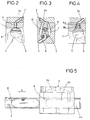
- Ein Ausführungsbeispiel der Erfindung wird nachfolgend anhand der Zeichnungen erläutert. Die Zeichnungen zeigen dabei in
- Fig. 1
- schaubildlich die erfindungsgemäße Anordnung, wobei ein Siebträger aus dem Gehäuse nach vorne vorgezogen ist, um das Filterelement auszuwechseln, in
- Fig. 2
- einen Schnitt durch Gehäuse und Siebträger im Bereich des Führungskanales, in
- Fig. 3
- einen Schnitt durch Gehäuse und Siebträger im Bereich der Mündung des rückwärtigen Zufuhrteilkanals, in
- Fig. 4
- eine abgeänderte Ausführungsformder Anordnung gemäß
Fig. 2 mit zwei Verbindungskanälen, in - Fig. 5
- schematisch eine Seitenansicht auf die Anordnung gemäß
Fig. 1 , in - Fig. 6
- schematisch eine Draufsicht auf die Anordnung gemäß
Fig. 1 und in - Fig. 7
- einen Siebträger, wenn dieser aus dem Gehäuse ausgezogen ist.
- In den Zeichnungen ist mit 1 ein Gehäuse bezeichnet, das einen Zufuhrkanal 2 und einen Abfuhrkanal 3 für verflüssigten Kunststoff aufweist, wobei auf dem Weg vom Zufuhrkanal 2 zum Abfuhrkanal 3 bei dem dargestellten Ausführungsbeispiel zwei Siebträger 4, 4a vorgesehen sind. In den Siebträgern sind - wie dies die
Fig. 3 zeigt - sogenannte Siebräume 7 oder Kavitäten ausgearbeitet, in denen Filterelemente bzw. Siebe 5 und 6 angeordnet sind, die bei dem inFig. 3 dargestellten Ausführungsbeispiel einander gegenüberliegend vorgesehen sind, so dass der zu filtrierende Kunststoff von außen zugeführt und im Inneren abgeführt wird. - Selbstverständlich bezieht sich die Erfindung auch auf einen Siebträger, in dem nur ein Sieb angeordnet ist.
- Vom Zufuhrkanal 2 aus teilt sich dieser in zwei Zufuhrteilkanäle 2a und 2b, wobei der Zufuhrteilkanal 2a in Siebwechselrichtung R führt, während der Zufuhrteilkanal 2b zur in Siebwechselrichtung R gesehenen rückwärtigen Schmutzsieboberfläche führt.
-
Fig. 2 zeigt, dass der Zufuhrteilkanal 2a dann, wenn im Siebraum 7 zwei einander gegenüberliegende Filterelemente 5 und 6 vorgesehen sind, im Gehäuse 1 ein Verbindungskanal 9 ausgearbeitet ist, der einenendes mit dem Zufuhrteilkanal 2a in Verbindung steht, anderenendes umfangsmäßig gesehen mittig, d. h. bei 12:00 Uhr, auf den Siebträger 4 mündet. Hier steht dieses Ende des Verbindungskanales 9 mit einem Führungskanal 8 in Verbindung, der zu den beiden Schmutzsiebseiten der Siebe 5 und 6 führt. Der Verbindungskanal 9 fluchtet mit einer entsprechenden Bohrung 12 im Siebträger 4 (Fig. 6 ), die die Verbindung zum Führungskanal 8 herstellt. -
Fig. 4 zeigt eine Ausführungsform, bei der der Zufuhrteilkanal 2a zu zwei im Gehäuse 1 ausgearbeiteten Verbindungskanälen 9a und 9b führt, die im Siebträger 4 in Führungen münden, die zu den beiden Schmutzsiebseiten der Siebe 5 und 6 führen. - Hieraus ist ersichtlich, dass bei einer Bewegung des Siebträgers 4 um eine Länge, die dem Durchmesser des Verbindungskanales 9 bzw. der beiden Verbindungskanäle 9a und 9b entspricht, eine Abtrennung der Siebräume 7 vom Zufuhrteilkanal 2a erfolgt.
- Der in Siebwechselrichtung R gesehen rückwärtige Zufuhrteilkanal 2b teilt sich noch innerhalb des Gehäuses 1 in zwei Verbindungskanäle 10 und 11, die ihrerseits in den Siebraum 7 auf der Schmutzsiebseite der Siebe 5 und 6 münden (siehe
Fig. 3 ). - An dieser Stelle sei ausdrücklich darauf hingewiesen, dass der Führungskanal 8 so wie in
Fig. 1 und inFig. 2 dargestellt als Bohrung innerhalb des Siebträgers 4 ausgeführt sein kann, dass aber in gleicher Weise die Möglichkeit besteht, dass der Verbindungskanal 9 in eine Nut an der Oberseite des Siebträgers 4 mündet, die anstelle des Führungskanales 8 vorgesehen ist. - In der Zeichnung nicht dargestellt ist die Möglichkeit, die vorbeschriebene Vorrichtung auch in der Rückspülversion auszubilden, wobei entsprechende Kanalführungen vorgesehen sein müssen.
Claims (7)
- Vorrichtung zum Filtrieren eines Fluids, insbesondere eines verflüssigten Kunststoffes mit einem Gehäuse (1) mit mindestens einem Zufuhrkanal (2), einem Abfuhrkanal (3), wobei im Strömungsweg des Fluids in mindestens einem quer zur Strömungsrichtung verschieblich gelagerten Siebträger (4, 4a) mindestens ein Sieb (5, 6) in einem entsprechenden Siebraum angeordnet und mit dem Zufuhrkanal (2) und dem Abfuhrkanal (3) in Verbindung bringbar ist, wobei das Sieb (5, 6) langgestreckt oval oder polygonal ausgebildet ist und der Zufuhrkanal (2) sich in zwei Zufuhrteilkanäle (2a, 2b) aufteilt, die in Siebwechselrichtung (R) hintereinander auf der Schmutzsiebseite in den Siebraum (7) münden,
dadurch gekennzeichnet,
dass der in Siebwechselrichtung (R) vordere Zufuhrteilkanal (2a) in einen im Siebträger (4) ausgearbeiteten Kanal (8) mündet, der den zu filternden Kunststoff dem Siebraum (7) zuführt. - Vorrichtung nach Anspruch 1, dadurch gekennzeichnet, das im Siebträger (4, 4a) zwei einander gegenüberliegende Filtersiebe (5, 6) in einem Siebraum (7) angeordnet sind, dass der in Siebwechselrichtung (R) hintere Zufuhrteilkanal (2b) sich umgekehrt V-förmig aufteilt und zu den beiden Sieben (5, 6) auf der Schmutzsiebseite führt und
dass der in Siebwechselrichtung (R) vordere Zufuhrteilkanal (2a) in einen im Siebträger (4) ausgearbeiteten Führungskanal (8) mündet, der zu den beiden Sieben (5, 6) auf der Schmutzsiebseite führt. - Vorrichtung nach Anspruch 2, dadurch gekennzeichnet, dass der Führungskanal (8) als Bohrung im Siebbolzen (4, 4a) vorgesehen ist.
- Vorrichtung nach Anspruch 2, dadurch gekennzeichnet, dass der Führungskanal (8) als Nut im Siebbolzen (4, 4a) ausgearbeitet ist.
- Vorrichtung nach Anspruch 2, dadurch gekennzeichnet, dass der Zufuhrteilkanal (2a) in zwei im Gehäuse (1) vorgesehene Verbindungskanäle (9a, 9b) mündet, die mittelbar oder unmittelbar zu den beiden Schmutzsiebseiten der Siebe (5, 6) führen.
- Vorrichtung nach Anspruch 2, 3 oder 4 dadurch gekennzeichnet, dass der Zufuhrteilkanal (2a) umfangsmäßig mittig auf den Siebbolzen (4) mündet und hier mit dem Führungskanal (8) in Verbindung steht.
- Vorrichtung nach Anspruch 5, dadurch gekennzeichnet, dass der Zufuhrteilkanal (2a) umfangsmäßig mitten auf dem Siebbolzen (4) mündet und hier mit den Verbindungskanälen (9a, 9b) in Verbindung steht.
Applications Claiming Priority (2)
| Application Number | Priority Date | Filing Date | Title |
|---|---|---|---|
| DE102007036013 | 2007-07-30 | ||
| DE102007059579A DE102007059579A1 (de) | 2007-07-30 | 2007-12-11 | Vorrichtung zum Filtrieren eines Fluids, insbesondere eines verflüssigten Kunststoffes |
Publications (2)
| Publication Number | Publication Date |
|---|---|
| EP2025495A1 EP2025495A1 (de) | 2009-02-18 |
| EP2025495B1 true EP2025495B1 (de) | 2011-04-27 |
Family
ID=40176027
Family Applications (1)
| Application Number | Title | Priority Date | Filing Date |
|---|---|---|---|
| EP08011387A Active EP2025495B1 (de) | 2007-07-30 | 2008-06-24 | Vorrichtung zum Filtrieren eines Fluids, insbesondere eines verflüssigten Kunststoffes |
Country Status (4)
| Country | Link |
|---|---|
| US (1) | US20090032456A1 (de) |
| EP (1) | EP2025495B1 (de) |
| AT (1) | ATE507054T1 (de) |
| DE (2) | DE102007059579A1 (de) |
Families Citing this family (1)
| Publication number | Priority date | Publication date | Assignee | Title |
|---|---|---|---|---|
| EP3308940B1 (de) * | 2016-10-17 | 2025-03-05 | Next Generation Analytics GmbH | Filtersystem für viskose oder hochviskose flüssigkeiten, insbesondere kunststoffschmelzen und verfahren zur filtration von viskosen oder hochviskosen flüssigkeiten |
Family Cites Families (9)
| Publication number | Priority date | Publication date | Assignee | Title |
|---|---|---|---|---|
| DE8701110U1 (de) | 1987-01-23 | 1987-03-19 | Trendelkamp, Josef, 4418 Nordwalde | Stützlochplatte für Thermoplast-Extruder |
| DE29517140U1 (de) | 1995-03-31 | 1996-01-18 | Kreyenborg Verwaltungen und Beteiligungen KG, 48157 Münster | Filtereinrichtung für Strangpressen und Spritzgießmaschinen |
| DE19834302C2 (de) | 1998-04-30 | 2001-02-22 | Kreyenborg Verwaltungen | Filtereinrichtung für Strangpressen und Spritzgießmaschinen |
| US6422852B1 (en) * | 1998-04-30 | 2002-07-23 | Kreyenborg Verwaltungen Und Beteiligungen Gmbh & Co. Kg | Filter device for extruders and injection moulding machines |
| AU2002220425A1 (en) * | 2001-12-14 | 2002-03-04 | Maag Pump Systems Textron Ag | Device for filtering liquid media, support body and a method for operating the device |
| AU2003299022A1 (en) * | 2002-09-17 | 2004-04-08 | Kreyenborg Verwaltungen Und Beteiligungen Gmbh And Co. Kg | Device for filtering a fluid, especially for plastic-processing installations |
| AT412530B (de) | 2002-10-28 | 2005-04-25 | Erema | Rückspülbare filtervorrichtung für geschmolzenes material und verteiler für eine solche filtervorrichtung |
| US7658535B2 (en) * | 2004-08-05 | 2010-02-09 | Koninklijke Philips Electronics, N.V. | Lamp having improved vibration damping |
| DE102005043096A1 (de) * | 2005-09-10 | 2007-03-15 | Kreyenborg Verwaltungen Und Beteiligungen Gmbh & Co. Kg | Vorrichtung zum Filtrieren eines Fluids, insbesondere für kunststoffverarbeitende Anlagen |
-
2007
- 2007-12-11 DE DE102007059579A patent/DE102007059579A1/de not_active Withdrawn
-
2008
- 2008-06-24 EP EP08011387A patent/EP2025495B1/de active Active
- 2008-06-24 AT AT08011387T patent/ATE507054T1/de active
- 2008-06-24 DE DE502008003337T patent/DE502008003337D1/de active Active
- 2008-07-16 US US12/174,311 patent/US20090032456A1/en not_active Abandoned
Also Published As
| Publication number | Publication date |
|---|---|
| ATE507054T1 (de) | 2011-05-15 |
| EP2025495A1 (de) | 2009-02-18 |
| DE502008003337D1 (de) | 2011-06-09 |
| US20090032456A1 (en) | 2009-02-05 |
| DE102007059579A1 (de) | 2009-02-05 |
Similar Documents
| Publication | Publication Date | Title |
|---|---|---|
| DE102012006563B3 (de) | Vorrichtung zum Filtrieren eines Fluids | |
| EP1423178B1 (de) | Vorrichtung zum filtrieren eines fluids, insbesondere für kunststoffverarbeitende anlagen | |
| EP0379966A2 (de) | Siebvorrichtung zur Reinigung von Kunststoffschmelzen | |
| EP2632686B1 (de) | Vorrichtung zum filtrieren einer kunststoffschmelze | |
| DE3941831C1 (de) | ||
| EP0540546B1 (de) | Filtriervorrichtung für thermoplastisches kunststoffmaterial | |
| DE102004036597B3 (de) | Vorrichtung und Verfahren zum Filtrieren eines Fluids, insbesondere für kunststoffverarbeitende Anlagen | |
| EP0536359B1 (de) | Siebwechselkassette | |
| DE10254022B4 (de) | Vorrichtung zum Filtrieren eines Fluids, insbesondere für kunststoffverarbeitende Anlagen | |
| DE102022106334A1 (de) | Filtriervorrichtung zum Filtrieren eines Fluids sowie betreffendes Betriebsverfahren | |
| EP2001651B1 (de) | Vorrichtung zum filtrieren eines verflüssigten kunststoffes | |
| DE4218756C1 (en) | Injection moulding machine and extrusion press filter appts. for thermoplastics - comprises barrier member in inlet channel prior to sieve bolt and housing for unimpeded plastic flow in open barrier position, for efficient continual working | |
| EP0875357A1 (de) | Filtereinrichtung für Strangpressen und Spritzgiessmaschinen | |
| EP1247635A2 (de) | Vorrichtung zum Filtrieren einer Flüssigkeit, insbesondere zum Filtrieren einer polymeren Kunststoffschmelze | |
| DE2130501A1 (de) | Vorrichtung zum Auswechseln von Sieben | |
| DE4125181C1 (en) | Filter appts. for extrusion presses, injection moulding machine etc. - includes sieve unit contg. plate(s) having filter candle-cartridges on dirty side | |
| EP2025495A1 (de) | Vorrichtung zum Filtrieren eines Fluids, insbesondere eines verflüssigten Kunststoffes | |
| WO2013182192A1 (de) | Filtriervorrichtung für fluide | |
| EP0919353A2 (de) | Vorrichtung zum Filtrieren eines Fluidstromes sowie Filtermodul zur Verwendung in einer entsprechenden Vorrichtung | |
| EP1524022B1 (de) | Vorrichtung zum Filtrieren eines Fluids, insbesondere für kunststoffverarbeitende Anlagen | |
| DE10317170A1 (de) | Vorrichtung zum Filtrieren eines Fluids, insbesondere für kunststoffverarbeitende Anlagen | |
| AT407361B (de) | Rückspülbare vorrichtung zum filtrieren von verunreinigtem, flüssigem bzw. plastifiziertem material | |
| DE29611292U1 (de) | Filtereinrichtung für Strangpreß- und Spritzgießmaschinen | |
| DE4126261C1 (en) | Simple and reliable filter arrangement for extrusion presses, etc. - including separate channel sectors between inlet and outlet channels and exchangeable sieve carrier, etc. | |
| EP1245366A2 (de) | Sperrmittel zur Steuerung des Durchflusses eines fliessfähigen Mediums |
Legal Events
| Date | Code | Title | Description |
|---|---|---|---|
| PUAI | Public reference made under article 153(3) epc to a published international application that has entered the european phase |
Free format text: ORIGINAL CODE: 0009012 |
|
| AK | Designated contracting states |
Kind code of ref document: A1 Designated state(s): AT BE BG CH CY CZ DE DK EE ES FI FR GB GR HR HU IE IS IT LI LT LU LV MC MT NL NO PL PT RO SE SI SK TR |
|
| AX | Request for extension of the european patent |
Extension state: AL BA MK RS |
|
| 17P | Request for examination filed |
Effective date: 20090407 |
|
| AKX | Designation fees paid |
Designated state(s): AT BE BG CH CY CZ DE DK EE ES FI FR GB GR HR HU IE IS IT LI LT LU LV MC MT NL NO PL PT RO SE SI SK TR |
|
| 17Q | First examination report despatched |
Effective date: 20100824 |
|
| GRAP | Despatch of communication of intention to grant a patent |
Free format text: ORIGINAL CODE: EPIDOSNIGR1 |
|
| GRAS | Grant fee paid |
Free format text: ORIGINAL CODE: EPIDOSNIGR3 |
|
| GRAA | (expected) grant |
Free format text: ORIGINAL CODE: 0009210 |
|
| AK | Designated contracting states |
Kind code of ref document: B1 Designated state(s): AT BE BG CH CY CZ DE DK EE ES FI FR GB GR HR HU IE IS IT LI LT LU LV MC MT NL NO PL PT RO SE SI SK TR |
|
| REG | Reference to a national code |
Ref country code: GB Ref legal event code: FG4D Free format text: NOT ENGLISH |
|
| REG | Reference to a national code |
Ref country code: CH Ref legal event code: EP |
|
| REG | Reference to a national code |
Ref country code: IE Ref legal event code: FG4D Free format text: LANGUAGE OF EP DOCUMENT: GERMAN |
|
| REF | Corresponds to: |
Ref document number: 502008003337 Country of ref document: DE Date of ref document: 20110609 Kind code of ref document: P |
|
| REG | Reference to a national code |
Ref country code: DE Ref legal event code: R096 Ref document number: 502008003337 Country of ref document: DE Effective date: 20110609 |
|
| REG | Reference to a national code |
Ref country code: CH Ref legal event code: NV Representative=s name: BRAUNPAT BRAUN EDER AG |
|
| REG | Reference to a national code |
Ref country code: NL Ref legal event code: VDEP Effective date: 20110427 |
|
| LTIE | Lt: invalidation of european patent or patent extension |
Effective date: 20110427 |
|
| PG25 | Lapsed in a contracting state [announced via postgrant information from national office to epo] |
Ref country code: SE Free format text: LAPSE BECAUSE OF FAILURE TO SUBMIT A TRANSLATION OF THE DESCRIPTION OR TO PAY THE FEE WITHIN THE PRESCRIBED TIME-LIMIT Effective date: 20110427 Ref country code: NO Free format text: LAPSE BECAUSE OF FAILURE TO SUBMIT A TRANSLATION OF THE DESCRIPTION OR TO PAY THE FEE WITHIN THE PRESCRIBED TIME-LIMIT Effective date: 20110727 Ref country code: HR Free format text: LAPSE BECAUSE OF FAILURE TO SUBMIT A TRANSLATION OF THE DESCRIPTION OR TO PAY THE FEE WITHIN THE PRESCRIBED TIME-LIMIT Effective date: 20110427 Ref country code: PT Free format text: LAPSE BECAUSE OF FAILURE TO SUBMIT A TRANSLATION OF THE DESCRIPTION OR TO PAY THE FEE WITHIN THE PRESCRIBED TIME-LIMIT Effective date: 20110829 Ref country code: LT Free format text: LAPSE BECAUSE OF FAILURE TO SUBMIT A TRANSLATION OF THE DESCRIPTION OR TO PAY THE FEE WITHIN THE PRESCRIBED TIME-LIMIT Effective date: 20110427 |
|
| REG | Reference to a national code |
Ref country code: IE Ref legal event code: FD4D |
|
| PG25 | Lapsed in a contracting state [announced via postgrant information from national office to epo] |
Ref country code: ES Free format text: LAPSE BECAUSE OF FAILURE TO SUBMIT A TRANSLATION OF THE DESCRIPTION OR TO PAY THE FEE WITHIN THE PRESCRIBED TIME-LIMIT Effective date: 20110807 Ref country code: IS Free format text: LAPSE BECAUSE OF FAILURE TO SUBMIT A TRANSLATION OF THE DESCRIPTION OR TO PAY THE FEE WITHIN THE PRESCRIBED TIME-LIMIT Effective date: 20110827 Ref country code: GR Free format text: LAPSE BECAUSE OF FAILURE TO SUBMIT A TRANSLATION OF THE DESCRIPTION OR TO PAY THE FEE WITHIN THE PRESCRIBED TIME-LIMIT Effective date: 20110728 Ref country code: SI Free format text: LAPSE BECAUSE OF FAILURE TO SUBMIT A TRANSLATION OF THE DESCRIPTION OR TO PAY THE FEE WITHIN THE PRESCRIBED TIME-LIMIT Effective date: 20110427 Ref country code: CY Free format text: LAPSE BECAUSE OF FAILURE TO SUBMIT A TRANSLATION OF THE DESCRIPTION OR TO PAY THE FEE WITHIN THE PRESCRIBED TIME-LIMIT Effective date: 20110427 Ref country code: FI Free format text: LAPSE BECAUSE OF FAILURE TO SUBMIT A TRANSLATION OF THE DESCRIPTION OR TO PAY THE FEE WITHIN THE PRESCRIBED TIME-LIMIT Effective date: 20110427 Ref country code: LV Free format text: LAPSE BECAUSE OF FAILURE TO SUBMIT A TRANSLATION OF THE DESCRIPTION OR TO PAY THE FEE WITHIN THE PRESCRIBED TIME-LIMIT Effective date: 20110427 |
|
| PG25 | Lapsed in a contracting state [announced via postgrant information from national office to epo] |
Ref country code: MT Free format text: LAPSE BECAUSE OF FAILURE TO SUBMIT A TRANSLATION OF THE DESCRIPTION OR TO PAY THE FEE WITHIN THE PRESCRIBED TIME-LIMIT Effective date: 20110427 Ref country code: NL Free format text: LAPSE BECAUSE OF FAILURE TO SUBMIT A TRANSLATION OF THE DESCRIPTION OR TO PAY THE FEE WITHIN THE PRESCRIBED TIME-LIMIT Effective date: 20110427 |
|
| BERE | Be: lapsed |
Owner name: KREYENBORG VERWALTUNGEN UND BETEILIGUNGEN G.M.B.H. Effective date: 20110630 |
|
| PG25 | Lapsed in a contracting state [announced via postgrant information from national office to epo] |
Ref country code: IE Free format text: LAPSE BECAUSE OF FAILURE TO SUBMIT A TRANSLATION OF THE DESCRIPTION OR TO PAY THE FEE WITHIN THE PRESCRIBED TIME-LIMIT Effective date: 20110427 Ref country code: EE Free format text: LAPSE BECAUSE OF FAILURE TO SUBMIT A TRANSLATION OF THE DESCRIPTION OR TO PAY THE FEE WITHIN THE PRESCRIBED TIME-LIMIT Effective date: 20110427 Ref country code: CZ Free format text: LAPSE BECAUSE OF FAILURE TO SUBMIT A TRANSLATION OF THE DESCRIPTION OR TO PAY THE FEE WITHIN THE PRESCRIBED TIME-LIMIT Effective date: 20110427 |
|
| PG25 | Lapsed in a contracting state [announced via postgrant information from national office to epo] |
Ref country code: PL Free format text: LAPSE BECAUSE OF FAILURE TO SUBMIT A TRANSLATION OF THE DESCRIPTION OR TO PAY THE FEE WITHIN THE PRESCRIBED TIME-LIMIT Effective date: 20110427 Ref country code: SK Free format text: LAPSE BECAUSE OF FAILURE TO SUBMIT A TRANSLATION OF THE DESCRIPTION OR TO PAY THE FEE WITHIN THE PRESCRIBED TIME-LIMIT Effective date: 20110427 Ref country code: DK Free format text: LAPSE BECAUSE OF FAILURE TO SUBMIT A TRANSLATION OF THE DESCRIPTION OR TO PAY THE FEE WITHIN THE PRESCRIBED TIME-LIMIT Effective date: 20110427 Ref country code: RO Free format text: LAPSE BECAUSE OF FAILURE TO SUBMIT A TRANSLATION OF THE DESCRIPTION OR TO PAY THE FEE WITHIN THE PRESCRIBED TIME-LIMIT Effective date: 20110427 |
|
| PLBE | No opposition filed within time limit |
Free format text: ORIGINAL CODE: 0009261 |
|
| STAA | Information on the status of an ep patent application or granted ep patent |
Free format text: STATUS: NO OPPOSITION FILED WITHIN TIME LIMIT |
|
| REG | Reference to a national code |
Ref country code: FR Ref legal event code: ST Effective date: 20120229 |
|
| PG25 | Lapsed in a contracting state [announced via postgrant information from national office to epo] |
Ref country code: BE Free format text: LAPSE BECAUSE OF NON-PAYMENT OF DUE FEES Effective date: 20110630 |
|
| 26N | No opposition filed |
Effective date: 20120130 |
|
| PG25 | Lapsed in a contracting state [announced via postgrant information from national office to epo] |
Ref country code: FR Free format text: LAPSE BECAUSE OF NON-PAYMENT OF DUE FEES Effective date: 20110630 |
|
| REG | Reference to a national code |
Ref country code: DE Ref legal event code: R097 Ref document number: 502008003337 Country of ref document: DE Effective date: 20120130 |
|
| GBPC | Gb: european patent ceased through non-payment of renewal fee |
Effective date: 20120624 |
|
| PG25 | Lapsed in a contracting state [announced via postgrant information from national office to epo] |
Ref country code: GB Free format text: LAPSE BECAUSE OF NON-PAYMENT OF DUE FEES Effective date: 20120624 Ref country code: MC Free format text: LAPSE BECAUSE OF NON-PAYMENT OF DUE FEES Effective date: 20110630 |
|
| PG25 | Lapsed in a contracting state [announced via postgrant information from national office to epo] |
Ref country code: LU Free format text: LAPSE BECAUSE OF NON-PAYMENT OF DUE FEES Effective date: 20110624 |
|
| PG25 | Lapsed in a contracting state [announced via postgrant information from national office to epo] |
Ref country code: BG Free format text: LAPSE BECAUSE OF FAILURE TO SUBMIT A TRANSLATION OF THE DESCRIPTION OR TO PAY THE FEE WITHIN THE PRESCRIBED TIME-LIMIT Effective date: 20110727 |
|
| PG25 | Lapsed in a contracting state [announced via postgrant information from national office to epo] |
Ref country code: TR Free format text: LAPSE BECAUSE OF FAILURE TO SUBMIT A TRANSLATION OF THE DESCRIPTION OR TO PAY THE FEE WITHIN THE PRESCRIBED TIME-LIMIT Effective date: 20110427 |
|
| PG25 | Lapsed in a contracting state [announced via postgrant information from national office to epo] |
Ref country code: HU Free format text: LAPSE BECAUSE OF FAILURE TO SUBMIT A TRANSLATION OF THE DESCRIPTION OR TO PAY THE FEE WITHIN THE PRESCRIBED TIME-LIMIT Effective date: 20110427 |
|
| REG | Reference to a national code |
Ref country code: DE Ref legal event code: R082 Ref document number: 502008003337 Country of ref document: DE Representative=s name: HABBEL & HABBEL, DE |
|
| REG | Reference to a national code |
Ref country code: CH Ref legal event code: PUE Owner name: NORDSON HOLDINGS S.A.R.L. AND CO. KG, DE Free format text: FORMER OWNER: KREYENBORG VERWALTUNGEN UND BETEILIGUNGEN GMBH AND CO. KG, DE |
|
| REG | Reference to a national code |
Ref country code: DE Ref legal event code: R082 Ref document number: 502008003337 Country of ref document: DE Representative=s name: HABBEL & HABBEL, DE Effective date: 20140917 Ref country code: DE Ref legal event code: R081 Ref document number: 502008003337 Country of ref document: DE Owner name: NORDSON HOLDINGS S.A.R.L. & CO. KG, DE Free format text: FORMER OWNER: KREYENBORG VERWALTUNGEN UND BETEILIGUNGEN GMBH & CO. KG, 48157 MUENSTER, DE Effective date: 20140917 Ref country code: DE Ref legal event code: R082 Ref document number: 502008003337 Country of ref document: DE Representative=s name: EISENFUEHR SPEISER PATENTANWAELTE RECHTSANWAEL, DE Effective date: 20140917 |
|
| REG | Reference to a national code |
Ref country code: AT Ref legal event code: PC Ref document number: 507054 Country of ref document: AT Kind code of ref document: T Owner name: NORDSON HOLDINGS S.A.R.L. & CO. KG, DE Effective date: 20150618 |
|
| REG | Reference to a national code |
Ref country code: DE Ref legal event code: R082 Ref document number: 502008003337 Country of ref document: DE Representative=s name: EISENFUEHR SPEISER PATENTANWAELTE RECHTSANWAEL, DE |
|
| REG | Reference to a national code |
Ref country code: CH Ref legal event code: PCAR Free format text: NEW ADDRESS: HOLEESTRASSE 87, 4054 BASEL (CH) |
|
| REG | Reference to a national code |
Ref country code: DE Ref legal event code: R079 Ref document number: 502008003337 Country of ref document: DE Free format text: PREVIOUS MAIN CLASS: B29C0047680000 Ipc: B29C0048690000 |
|
| P01 | Opt-out of the competence of the unified patent court (upc) registered |
Effective date: 20230530 |
|
| PGFP | Annual fee paid to national office [announced via postgrant information from national office to epo] |
Ref country code: DE Payment date: 20250618 Year of fee payment: 18 |
|
| PGFP | Annual fee paid to national office [announced via postgrant information from national office to epo] |
Ref country code: AT Payment date: 20250620 Year of fee payment: 18 |
|
| PGFP | Annual fee paid to national office [announced via postgrant information from national office to epo] |
Ref country code: IT Payment date: 20250624 Year of fee payment: 18 |
|
| PGFP | Annual fee paid to national office [announced via postgrant information from national office to epo] |
Ref country code: CH Payment date: 20250701 Year of fee payment: 18 |