EP2025108B1 - Method and system for dynamically configuring a traffic flow template - Google Patents
Method and system for dynamically configuring a traffic flow template Download PDFInfo
- Publication number
- EP2025108B1 EP2025108B1 EP07734480A EP07734480A EP2025108B1 EP 2025108 B1 EP2025108 B1 EP 2025108B1 EP 07734480 A EP07734480 A EP 07734480A EP 07734480 A EP07734480 A EP 07734480A EP 2025108 B1 EP2025108 B1 EP 2025108B1
- Authority
- EP
- European Patent Office
- Prior art keywords
- downlink
- packet
- tft
- network node
- packets
- Prior art date
- Legal status (The legal status is an assumption and is not a legal conclusion. Google has not performed a legal analysis and makes no representation as to the accuracy of the status listed.)
- Not-in-force
Links
- 238000000034 method Methods 0.000 title claims abstract description 29
- 238000001914 filtration Methods 0.000 claims abstract description 8
- 239000000284 extract Substances 0.000 abstract description 2
- 206010051686 Pachydermoperiostosis Diseases 0.000 description 9
- 201000006652 primary hypertrophic osteoarthropathy Diseases 0.000 description 9
- 101100489584 Solanum lycopersicum TFT1 gene Proteins 0.000 description 6
- 238000010586 diagram Methods 0.000 description 6
- 238000012986 modification Methods 0.000 description 3
- 230000004048 modification Effects 0.000 description 3
- 101100214488 Solanum lycopersicum TFT2 gene Proteins 0.000 description 2
- 230000004913 activation Effects 0.000 description 2
- 230000008901 benefit Effects 0.000 description 2
- 230000005540 biological transmission Effects 0.000 description 2
- 238000004891 communication Methods 0.000 description 2
- 230000007246 mechanism Effects 0.000 description 2
- 229910000906 Bronze Inorganic materials 0.000 description 1
- 230000003213 activating effect Effects 0.000 description 1
- 238000013459 approach Methods 0.000 description 1
- 239000010974 bronze Substances 0.000 description 1
- KUNSUQLRTQLHQQ-UHFFFAOYSA-N copper tin Chemical compound [Cu].[Sn] KUNSUQLRTQLHQQ-UHFFFAOYSA-N 0.000 description 1
- 230000004069 differentiation Effects 0.000 description 1
- 238000011156 evaluation Methods 0.000 description 1
- 238000007689 inspection Methods 0.000 description 1
- 238000012544 monitoring process Methods 0.000 description 1
- HRULVFRXEOZUMJ-UHFFFAOYSA-K potassium;disodium;2-(4-chloro-2-methylphenoxy)propanoate;methyl-dioxido-oxo-$l^{5}-arsane Chemical compound [Na+].[Na+].[K+].C[As]([O-])([O-])=O.[O-]C(=O)C(C)OC1=CC=C(Cl)C=C1C HRULVFRXEOZUMJ-UHFFFAOYSA-K 0.000 description 1
- 238000012545 processing Methods 0.000 description 1
- 230000004044 response Effects 0.000 description 1
- 230000011664 signaling Effects 0.000 description 1
- 229910052709 silver Inorganic materials 0.000 description 1
- 239000004332 silver Substances 0.000 description 1
- 230000003068 static effect Effects 0.000 description 1
Images



Classifications
-
- H—ELECTRICITY
- H04—ELECTRIC COMMUNICATION TECHNIQUE
- H04L—TRANSMISSION OF DIGITAL INFORMATION, e.g. TELEGRAPHIC COMMUNICATION
- H04L45/00—Routing or path finding of packets in data switching networks
- H04L45/302—Route determination based on requested QoS
-
- H—ELECTRICITY
- H04—ELECTRIC COMMUNICATION TECHNIQUE
- H04L—TRANSMISSION OF DIGITAL INFORMATION, e.g. TELEGRAPHIC COMMUNICATION
- H04L45/00—Routing or path finding of packets in data switching networks
- H04L45/302—Route determination based on requested QoS
- H04L45/306—Route determination based on the nature of the carried application
-
- H—ELECTRICITY
- H04—ELECTRIC COMMUNICATION TECHNIQUE
- H04W—WIRELESS COMMUNICATION NETWORKS
- H04W76/00—Connection management
- H04W76/20—Manipulation of established connections
- H04W76/22—Manipulation of transport tunnels
-
- H—ELECTRICITY
- H04—ELECTRIC COMMUNICATION TECHNIQUE
- H04W—WIRELESS COMMUNICATION NETWORKS
- H04W28/00—Network traffic management; Network resource management
- H04W28/16—Central resource management; Negotiation of resources or communication parameters, e.g. negotiating bandwidth or QoS [Quality of Service]
Definitions
- the present invention relates to data communication in wireless networks and user equipment. More particularly, and not by way of limitation, the present invention is directed to a system and method for dynamically configuring a Traffic Flow Template (TFT) in a Third Generation Partnership Project (3GPP) wireless communication network.
- TFT Traffic Flow Template
- 3GPP Third Generation Partnership Project
- the default bearer enables packet transmission between a User Equipment (UE) and a gateway.
- UE User Equipment
- User differentiation for a default bearer may be possible; that is, the service level of a particular user's default bearer could be "god”, “silver”, or “bronze” based on a user's subscription data with the service.
- a bearer is a point-to-point connection from the user terminal to the IP network provided by either the operator or an Internet Service Provider (ISP).
- ISP Internet Service Provider
- QoS Quality of Service
- the QoS profile contains parameters such as peak throughput, mean throughput, delay, and reliability.
- a bearer may be either a primary bearer or a secondary bearer.
- a primary, or default, bearer has a unique IP address assigned, while a secondary, or dedicated, bearer has the same IP address as the primary bearer if the secondary bearer is activated.
- the secondary bearer normally has a different QoS profile than the primary bearer.
- the primary bearer is typically activated to different Access Point Names (APNs), while the secondary bearer is connected to the same APN as the primary.
- APIs Access Point Names
- a typical scenario where a primary and a secondary bearer are activated is when there are both UDP and TCP traffic.
- a primary bearer with low reliability may be activated for the UDP traffic, and a secondary bearer with high reliability may be activated for the TCP traffic.
- Another scenario is a multimedia streaming session, in which there is one bearer with high throughput for the payload, and a second bearer with different characteristics for signaling.
- TFT Traffic Flow Template
- FIG. 1 is a high level block diagram of an existing network configuration for directing downlink traffic to the correct PDP context or bearer.
- a Gateway GPRS Support Node (GGSN) 11 receives packets through an ISP connection 12. When more than one bearer is established, different packets may be handled with different QoS and the GGSN must put them onto the correct PDP bearer (for example, Context1 13 or Context2 14).
- the downlink packets are put onto the correct bearer through the use of packet filtering specified by Traffic Flow Templates (TFTs) 15 and 16 (defined by 3GPP in Technical Specification 23.060). Each TFT is associated with a particular bearer.
- TFTs Traffic Flow Templates
- a TFT may contain up to 8 packet filters, and each packet filer may contain attributes such as protocol number, source or destination port, or source IP address (and more).
- the ISP connection 12 provides the entire downlink flow to each TFT, and each TFT determines which packets meet the filter attributes for its associated bearer. A packet must match at least one of the packet filters in the TFT in order to enter the associated downlink bearer for transmission to the mobile station (MS) 17. Otherwise, the packet is dropped.
- TFTs must be configured manually prior to context activation, and if the TFTs are set static for the context, there may be some applications that have a behavior requiring the TFTs to be more dynamic. If the TFTs are set too general (broad), packets not belonging to the bearer may be allowed to enter, and if the TFTs are set too specific (narrow), packets belonging to the bearer may be rejected. Depending on the kind of traffic flowing, the packet attributes can be quite dynamic, which can lead to a need to use a broadly defined packet filter.
- the present invention provides a system and method in which the Traffic Flow Template (TFT) is configured in real time as the traffic flows.
- TFT Traffic Flow Template
- the invention eliminates the difficult task of manually configuring the TFT prior to traffic flow, before it is determined which host is being communicated with and which application is running.
- the present invention is directed to a method in a network node for dynamically adapting a TFT to control the routing of downlink data packets from the network node to a user node.
- the method includes the steps of receiving an uplink data packet sent on a premium bearer channel from the user node; extracting from the uplink data packet, parameters which include at least the destination address of the uplink data packet; and defining a downlink packet filter subset for filtering downlink data packets as a function of the extracted parameters.
- the downlink packet filter subset identifies downlink data packets having a source address that matches the destination address of the uplink data packet.
- the TFT is then modified as a function of the downlink packet filter subset to route the identified downlink packets through the premium bearer channel to the user node, and to route differently, downlink data packets having source addresses that do not match the destination address of the uplink data packet.
- the present invention is directed to a network node operative to dynamically adapt a TFT to control the routing of downlink data packets from the network node to a user node.
- the network node includes means for receiving an uplink data packet sent on a premium bearer channel from the user node; means for extracting from the uplink data packet, parameters which include at least the destination address of the uplink data packet; and means for defining a downlink packet filter subset for filtering downlink data packets as a function of the extracted parameters.
- the downlink packet filter subset identifies downlink data packets having a source address that matches the destination address of the uplink data packet.
- the network node also includes means for modifying the TFT as a function of the downlink packet filter subset to route the identified downlink packets through the premium bearer channel to the user node, and to route differently, downlink data packets having source addresses that do not match the destination address of the uplink data packet.
- FIG. 2 is a high level block diagram depicting a TFT controller in accordance with a first embodiment of the present invention.
- a modified MS 21 includes TFT controllers 22 and 23, which act as Uplink Packet Filters (ULPFs) for packets entering Context1 13 and Context2 14, respectively.
- ULPFs Uplink Packet Filters
- the premium bearer is a special purpose bearer (or logical channel, tunnel, context, etc.) for transporting packets belonging, for example, to a premium application.
- the premium bearer may be pre-established by the GGSN when the MS attaches to the network at power on. This alternative is best suited for shared channel systems such as HSPA and LTE. Another alternative is to establish the premium bearer as an on-demand service.
- the user explicitly requests the service, for example, by clicking a link on the operator's portal, or by calling the operator via phone ("premium service for 2 hours for X dollars") which then triggers the GGSN to initiate a corresponding secondary or dedicated bearer.
- the TFT controllers 22 and 23 filter on predefined information parameters of the uplink traffic packets and place packets meeting the criteria for the premium application on the premium bearer. All other "Internet Access" client/peer applications are associated with the default service level.
- the TFT controllers also report predefined information parameters of the uplink traffic packets via TFT control signals 24 and 25 to TFT1 15 and TFT2 16 in the GGSN 11.
- This mechanism provides the configuration information needed by the downlink packet filters in TFT1 and TFT2 to place premium downlink packets on the premium bearer while placing all other packets on the default bearer.
- Most IP traffic is bi-directional (for example, TCP data+acks), and the premium traffic in both directions should go onto the premium bearer. It should be noted that a TCP download may be slowed down by either congestion on the data path or congestion on the ack path.
- the present invention helps to eliminate this congestion by dynamically configuring the TFTs with the proper filtering information so that packets can be properly directed even under changing conditions.
- the destination address of uplink packets is matched to the source address of downlink packets.
- the destination address of the uplink packets may take several forms, for example, simply the destination-IP-address or the destination-IP-address + destination-port-number.
- the GGSN 11 places downlink packets onto the same bearer from which the uplink packet with the matching address was received.
- TFT controllers may filter on any combination of IP header fields, or may even filter beyond the IP header fields, for example based on URLs in HTTP requests (i.e., ULPF based on deep packet inspection).
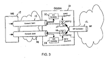
- FIG. 3 is a high level block diagram depicting a TFT controller in accordance with a second embodiment of the present invention.
- a GGSN 31 is modified to include TFT controllers 32 and 33.
- this embodiment is based on the fact that most Internet traffic has a symmetric behavior. That is, traffic tends to flow in both directions between two hosts. It is rare that traffic is unidirectional between two hosts. For example, for TCP traffic there will always be ACKs flowing in the opposite direction of the payload. This fact may be used to extract information from the uplink traffic that is used to configure the TFTs 15 and 16 in the GGSN for matching the expected downlink traffic.
- the TFT controllers 32 and 33 include a mechanism for monitoring uplink traffic per context, and for extracting all or part of the following information parameters from the uplink packet:
- the extracted information must be slightly modified before it can be used to determine the characteristics of an expected downlink packet.
- the modification may be as follows:
- FIG. 4 is a flow chart of an embodiment of the method of the present invention for modifying filter subsets for a premium bearer by the TFT controller 32 and 33.
- the TFT controllers extract the relevant parameters listed above (source and destination address, source and destination port, etc.) from a premium uplink packet and modify the parameters for use with downlink packets as shown above.
- the modified parameters are copied into a new packet filter subset.
- the dynamic filters for the premium bearer in the appropriate TFT (for example TFT1 15) in the GGSN 31 are compared to the new packet filter subset to determine if the modified parameters copied from the uplink packet into the packet filter subset are covered by an existing dynamic filter.
- step 44 TFT1 returns a response to the TFT controller 32 indicating the existence of the dynamic filter. If not, the method moves to step 45 where TFT1 returns an index to the next available filter.
- step 46 a packet filter is configured in TFT1.
- a search of the existing filters will be made to determine if any of the existing filters can be concatenated with the newly constructed packet filter subset.
- the filters must match the protocol id and as many as possible of the other filter tags. If none of the existing filters can be concatenated with the newly constructed packet filter subset, the method ends at step 48. However, if a "matching filter" is found, the method moves to step 49 where the filter is concatenated with, and stored in, the packet filter subset.
- the concatenated filter contains the common parameters and wildcards for the differing parameters in the combined matching filter and packet filter subset.
- the packet filter in the TFT identified by the filter index is configured with the appropriate information from the now modified packet filter subset, which results in a context modification toward the GGSN.
- the TFT controller may specify a filter with the expected source and destination port, expected source address, and protocol number. But since the number of packet filters are limited to 8, this approach limits the number of connections to 8 as well, since one packet filter is mapped to one connection.
- the TFT controller may try to concatenate packet filters. Packet filters with overlapping filter elements according to Table 1 below have the potential to be concatenated. Table 1 shows Protocol ID as one of the parameters, but for IPv6 traffic, this would be Next Header. Table 1 Concatenated Filter 1 Concatenated Filter 2 Concatenated Filter 3 Concatenated Filter 4 Source address X X Protocol ID X X X X X Destination port X X Source port X X
- Each packet filter in the TFT has an evaluation precedence field, which indicates the precedence of the packet filter compared to the other packet filters in the TFT.
- the TFT controller should set this high for narrow filters and lower for wider filters to ensure correct processing of the downlink packets.
- a narrow filter is a filter with many filter components.
- a wide filter is a filter with few components, and in special cases, only protocol ID is set.
- a user-configured packet filter is implemented in the TFT in addition to the packet filters created by the TFT controller.
- the user-configured packet filter may be utilized when the user has special requirements for packet handling.
- User-defined packet filters may be set in the PDP context activation procedure or in the PDP context modification procedure according to 3GPP 23.060.
- the present invention provides the advantage that the TFT does not need to be configured before the traffic flows.
- the invention also eliminates the need for manual configuration, which is a difficult task because the traffic strongly depends on which host is being communicated with and which application is running.
- the TFT controller may be implemented in the GGSN, the MS, the driver in the connected terminal equipment (TE), or in any network node through which the data packets pass between the MS and the GGSN.
- the TFT controller may be implemented in a base station or Serving GPRS Service Node (SGSN) serving the MS.
- the TFT controller may also be implemented in a 3GPP Packet Data Network (PDN) Gateway or Serving Gateway as defined in 3GPP Technical Specification 23.401 v0.4.1, or in an evolved Packet Data Gateway (ePDG) as defined in 3GPP Technical Specification 23.402 v0.4.0.
- PDN Packet Data Network
- ePDG evolved Packet Data Gateway
Landscapes
- Engineering & Computer Science (AREA)
- Computer Networks & Wireless Communication (AREA)
- Signal Processing (AREA)
- Mobile Radio Communication Systems (AREA)
- Data Exchanges In Wide-Area Networks (AREA)
Abstract
Description
- This application claims the benefit of the filing date of
U.S. Provisional Patent Application Number 60/746,529 filed on May 5, 2006 WO 2007/129199 . - The present invention relates to data communication in wireless networks and user equipment. More particularly, and not by way of limitation, the present invention is directed to a system and method for dynamically configuring a Traffic Flow Template (TFT) in a Third Generation Partnership Project (3GPP) wireless communication network.
- Operators usually offer an "Internet Access" service via a so-called default bearer. The default bearer enables packet transmission between a User Equipment (UE) and a gateway. User differentiation for a default bearer may be possible; that is, the service level of a particular user's default bearer could be "god", "silver", or "bronze" based on a user's subscription data with the service.
- In 3G networks the connection to an IP network is offered trough the use of bearers such as a PDP context or a Service Architecture Evolution (SAE) bearer. A bearer is a point-to-point connection from the user terminal to the IP network provided by either the operator or an Internet Service Provider (ISP). For each bearer it is possible to specify a Quality of Service (QoS) profile. The QoS profile contains parameters such as peak throughput, mean throughput, delay, and reliability.
- It is also possible to activate more than one bearer for a given user. A bearer may be either a primary bearer or a secondary bearer. A primary, or default, bearer has a unique IP address assigned, while a secondary, or dedicated, bearer has the same IP address as the primary bearer if the secondary bearer is activated. The secondary bearer normally has a different QoS profile than the primary bearer. The primary bearer is typically activated to different Access Point Names (APNs), while the secondary bearer is connected to the same APN as the primary.
- A typical scenario where a primary and a secondary bearer are activated is when there are both UDP and TCP traffic. A primary bearer with low reliability may be activated for the UDP traffic, and a secondary bearer with high reliability may be activated for the TCP traffic. Another scenario is a multimedia streaming session, in which there is one bearer with high throughput for the payload, and a second bearer with different characteristics for signaling.
- When more than one PDP bearer is established for a user, different packets may be handled with different QoS and should therefore be put onto the correct bearer. Traffic from a Gateway GPRS Support Node (GGSN) towards the UE is put onto the correct bearer through the use of packet filtering specified by a Traffic Flow Template (TFT) (defined by 3GPP in Technical Specification 23.060). Each bearer can have a TFT specified. A TFT may contain up to eight packet filters, and each packet filter may contain attributes such as protocol number, source or destination port, or source IP address (and more). If a packet enters a downlink bearer, the packet must match at least one of the packet filters in the TFT.
-
FIG. 1 is a high level block diagram of an existing network configuration for directing downlink traffic to the correct PDP context or bearer. A Gateway GPRS Support Node (GGSN) 11 receives packets through anISP connection 12. When more than one bearer is established, different packets may be handled with different QoS and the GGSN must put them onto the correct PDP bearer (for example,Context1 13 or Context2 14). The downlink packets are put onto the correct bearer through the use of packet filtering specified by Traffic Flow Templates (TFTs) 15 and 16 (defined by 3GPP in Technical Specification 23.060). Each TFT is associated with a particular bearer. A TFT may contain up to 8 packet filters, and each packet filer may contain attributes such as protocol number, source or destination port, or source IP address (and more). TheISP connection 12 provides the entire downlink flow to each TFT, and each TFT determines which packets meet the filter attributes for its associated bearer. A packet must match at least one of the packet filters in the TFT in order to enter the associated downlink bearer for transmission to the mobile station (MS) 17. Otherwise, the packet is dropped. - The establishment of a secondary PDP context while at least some filters required for the connection are not available, is described in
WO 02/073989 - A problem arises when trying to configure the TFTs in the GGSN for downlink packet traffic. The TFTs must be configured manually prior to context activation, and if the TFTs are set static for the context, there may be some applications that have a behavior requiring the TFTs to be more dynamic. If the TFTs are set too general (broad), packets not belonging to the bearer may be allowed to enter, and if the TFTs are set too specific (narrow), packets belonging to the bearer may be rejected. Depending on the kind of traffic flowing, the packet attributes can be quite dynamic, which can lead to a need to use a broadly defined packet filter.
- It would be advantageous to have a system and method for dynamically configuring TFTs that overcomes the disadvantages of the prior art. The present invention provides such a system and method.
- The present invention provides a system and method in which the Traffic Flow Template (TFT) is configured in real time as the traffic flows. The invention eliminates the difficult task of manually configuring the TFT prior to traffic flow, before it is determined which host is being communicated with and which application is running.
- In one aspect, the present invention is directed to a method in a network node for dynamically adapting a TFT to control the routing of downlink data packets from the network node to a user node. The method includes the steps of receiving an uplink data packet sent on a premium bearer channel from the user node; extracting from the uplink data packet, parameters which include at least the destination address of the uplink data packet; and defining a downlink packet filter subset for filtering downlink data packets as a function of the extracted parameters. The downlink packet filter subset identifies downlink data packets having a source address that matches the destination address of the uplink data packet. The TFT is then modified as a function of the downlink packet filter subset to route the identified downlink packets through the premium bearer channel to the user node, and to route differently, downlink data packets having source addresses that do not match the destination address of the uplink data packet.
- In another aspect, the present invention is directed to a network node operative to dynamically adapt a TFT to control the routing of downlink data packets from the network node to a user node. The network node includes means for receiving an uplink data packet sent on a premium bearer channel from the user node; means for extracting from the uplink data packet, parameters which include at least the destination address of the uplink data packet; and means for defining a downlink packet filter subset for filtering downlink data packets as a function of the extracted parameters. The downlink packet filter subset identifies downlink data packets having a source address that matches the destination address of the uplink data packet. The network node also includes means for modifying the TFT as a function of the downlink packet filter subset to route the identified downlink packets through the premium bearer channel to the user node, and to route differently, downlink data packets having source addresses that do not match the destination address of the uplink data packet.
- In the following section, the invention will be described with reference to exemplary embodiments illustrated in the figures, in which:
-
FIG. 1 is a high level block diagram of an existing network configuration for directing downlink traffic to the correct PDP context or bearer; -
FIG. 2 is a high level block diagram depicting a TFT controller in accordance with a first embodiment of the present invention; -
FIG. 3 is a high level block diagram depicting a TFT controller in accordance with a second embodiment of the present invention; and -
FIG. 4 is a flow chart of an embodiment of the method of the present invention. -
FIG. 2 is a high level block diagram depicting a TFT controller in accordance with a first embodiment of the present invention. In this embodiment, a modified MS 21 includesTFT controllers packets entering Context1 13 andContext2 14, respectively. - It should be noted that there are various ways in which a so-called premium bearer may be established. The premium bearer is a special purpose bearer (or logical channel, tunnel, context, etc.) for transporting packets belonging, for example, to a premium application. As a subscription service, the premium bearer may be pre-established by the GGSN when the MS attaches to the network at power on. This alternative is best suited for shared channel systems such as HSPA and LTE. Another alternative is to establish the premium bearer as an on-demand service. The user (human) explicitly requests the service, for example, by clicking a link on the operator's portal, or by calling the operator via phone ("premium service for 2 hours for X dollars") which then triggers the GGSN to initiate a corresponding secondary or dedicated bearer.
- The
TFT controllers - The TFT controllers also report predefined information parameters of the uplink traffic packets via TFT control signals 24 and 25 to TFT1 15 and
TFT2 16 in the GGSN 11. This mechanism provides the configuration information needed by the downlink packet filters in TFT1 and TFT2 to place premium downlink packets on the premium bearer while placing all other packets on the default bearer. Most IP traffic is bi-directional (for example, TCP data+acks), and the premium traffic in both directions should go onto the premium bearer. It should be noted that a TCP download may be slowed down by either congestion on the data path or congestion on the ack path. The present invention helps to eliminate this congestion by dynamically configuring the TFTs with the proper filtering information so that packets can be properly directed even under changing conditions. - In one embodiment, the destination address of uplink packets is matched to the source address of downlink packets. The destination address of the uplink packets may take several forms, for example, simply the destination-IP-address or the destination-IP-address + destination-port-number. In this case, the GGSN 11 places downlink packets onto the same bearer from which the uplink packet with the matching address was received.
- More advanced TFT controllers may also be utilized. For example, a TFT controller may filter on any combination of IP header fields, or may even filter beyond the IP header fields, for example based on URLs in HTTP requests (i.e., ULPF based on deep packet inspection).
-
FIG. 3 is a high level block diagram depicting a TFT controller in accordance with a second embodiment of the present invention. In this embodiment, aGGSN 31 is modified to includeTFT controllers TFTs - To do this, it is assumed that packets flowing uplink are mapped to the correct context. The invention is also useful when a context with a wide scope allows packets that are rejected by a narrow TFT to flow downlink, typical in a best efforts manner.
- The
TFT controllers - Destination address;
- Protocol number (IPv4);
- NextHeader (IPv6);
- Destination port;
- Source port;
- IP security parameter index;
- Type of service (IPv4;
- Traffic class (IPv6); and
- Flow Label (IPv6).
- The extracted information must be slightly modified before it can be used to determine the characteristics of an expected downlink packet. The modification may be as follows:
- Destination address must be regarded as expected source address;
- Destination port must be regarded as expected source port; and
- Source port must be regarded as expected destination port.
-
FIG. 4 is a flow chart of an embodiment of the method of the present invention for modifying filter subsets for a premium bearer by theTFT controller step 41, the TFT controllers extract the relevant parameters listed above (source and destination address, source and destination port, etc.) from a premium uplink packet and modify the parameters for use with downlink packets as shown above. Atstep 42, the modified parameters are copied into a new packet filter subset. Atstep 43, the dynamic filters for the premium bearer in the appropriate TFT (for example TFT1 15) in theGGSN 31 are compared to the new packet filter subset to determine if the modified parameters copied from the uplink packet into the packet filter subset are covered by an existing dynamic filter. If so, the method moves to step 44 where TFT1 returns a response to theTFT controller 32 indicating the existence of the dynamic filter. If not, the method moves to step 45 where TFT1 returns an index to the next available filter. Atstep 46, a packet filter is configured in TFT1. - At
step 47, a search of the existing filters will be made to determine if any of the existing filters can be concatenated with the newly constructed packet filter subset. The filters must match the protocol id and as many as possible of the other filter tags. If none of the existing filters can be concatenated with the newly constructed packet filter subset, the method ends atstep 48. However, if a "matching filter" is found, the method moves to step 49 where the filter is concatenated with, and stored in, the packet filter subset. The concatenated filter contains the common parameters and wildcards for the differing parameters in the combined matching filter and packet filter subset. Atstep 50, the packet filter in the TFT identified by the filter index is configured with the appropriate information from the now modified packet filter subset, which results in a context modification toward the GGSN. - In its simplest form, the TFT controller may specify a filter with the expected source and destination port, expected source address, and protocol number. But since the number of packet filters are limited to 8, this approach limits the number of connections to 8 as well, since one packet filter is mapped to one connection. When more packet filters are configured, the TFT controller may try to concatenate packet filters. Packet filters with overlapping filter elements according to Table 1 below have the potential to be concatenated. Table 1 shows Protocol ID as one of the parameters, but for IPv6 traffic, this would be Next Header.
Table 1 Concatenated Filter 1 Concatenated Filter 2 Concatenated Filter 3 Concatenated Filter 4 Source address X X Protocol ID X X X X Destination port X X Source port X X - For example, this would mean that if two packet filters are identical in the filter components source address, protocol id, and source port, but do not match in the destination port, they could be concatenated to one packet filter with a wider scope consisting of the common filter components.
- Each packet filter in the TFT has an evaluation precedence field, which indicates the precedence of the packet filter compared to the other packet filters in the TFT. The TFT controller should set this high for narrow filters and lower for wider filters to ensure correct processing of the downlink packets. A narrow filter is a filter with many filter components. A wide filter is a filter with few components, and in special cases, only protocol ID is set.
- In another embodiment when using a TFT controller, a user-configured packet filter is implemented in the TFT in addition to the packet filters created by the TFT controller. The user-configured packet filter may be utilized when the user has special requirements for packet handling. User-defined packet filters may be set in the PDP context activation procedure or in the PDP context modification procedure according to 3GPP 23.060.
- The present invention provides the advantage that the TFT does not need to be configured before the traffic flows. The invention also eliminates the need for manual configuration, which is a difficult task because the traffic strongly depends on which host is being communicated with and which application is running.
- In alternative embodiments, the TFT controller may be implemented in the GGSN, the MS, the driver in the connected terminal equipment (TE), or in any network node through which the data packets pass between the MS and the GGSN. For example, the TFT controller may be implemented in a base station or Serving GPRS Service Node (SGSN) serving the MS. The TFT controller may also be implemented in a 3GPP Packet Data Network (PDN) Gateway or Serving Gateway as defined in 3GPP Technical Specification 23.401 v0.4.1, or in an evolved Packet Data Gateway (ePDG) as defined in 3GPP Technical Specification 23.402 v0.4.0.
- The invention is not limited to the parameters used in text and example, but could include other parameters from the packet filters. As will be recognized by those skilled in the art, the innovative concepts described in the present application can be modified and varied over a wide range of applications. Accordingly, the scope of patented subject matter should not be limited to any of the specific exemplary teachings discussed above, but is instead defined by the following claims.
Claims (17)
- A method in a network node for dynamically adapting a Traffic Flow Template (TFT) to control the routing of downlink data packets from the network node to a user node, the method comprising the steps of:receiving an uplink data packet sent on a premium bearer channel from the user node, wherein the premium bearer is a special bearer adapted to transport data packets of premium data traffic;extracting parameters from the uplink data packet, the parameters comprising at least the destination address of the uplink data packet;defining a downlink packet filter subset for filtering downlink data packets as a function of the extracted parameters, wherein the downlink packet filter subset identifies downlink data packets having a source address that matches the destination address of the uplink data packet; andmodifying the TFT as a function of the downlink packet filter subset to route the identified downlink packets through the premium bearer channel to the user node, and to route differently, downlink data packets having source addresses that do not match the destination address of the uplink data packet.
- The method recited in claim 1, wherein the step of modifying the TFT includes the steps of:comparing the downlink packet filter subset to existing downlink packet filters in the TFT for the premium bearer to determine whether one of the existing downlink packet filters permits the routing of the identified downlink packets through the premium bearer channel; andif not, updating one of the existing downlink packet filters, as a function of the downlink packet filter subset, to permit the routing of the identified downlink packets through the premium bearer channel.
- The method recited in claim 1, wherein the step of modifying the TFT includes adding the downlink packet filter subset to the TFT.
- The method recited in claim 1, wherein the steps of extracting and defining a packet filter subset are performed by a TFT Controller in the network node.
- The method recited in claim 4, wherein the method is performed in a Gateway General Packet Radio Service (GPRS) Support Node (GGSN).
- The method recited in claim 4, wherein the method is performed in a 3GPP Packet Data Network (PDN) Gateway.
- The method recited in claim 4, wherein the method is performed in a 3GPP Serving Gateway.
- The method recited in claim 4, wherein the method is performed in a 3GPP evolved Packet Data Gateway (ePDG).
- A network node operative to dynamically adapt a Traffic Flow Template (TFT) to control the routing of downlink data packets from the network node to a user node, the network node comprising:means for receiving an uplink data packet sent on a premium bearer channel from the user node wherein the premium bearer is a special bearer adapted to transport data packets of premium data traffic;means for extracting parameters from the uplink data packet, the parameters comprising at least the destination address of the uplink data packet;means for defining a downlink packet filter subset for filtering downlink data packets as a function of the extracted parameters, wherein the downlink packet filter subset identifies downlink data packets having a source address that matches the destination address of the uplink data packet; andmeans for modifying the TFT as a function of the downlink packet filter subset to route the identified downlink packets through the premium bearer channel to the user node, and to route differently, downlink data packets having source addresses that do not match the destination address of the uplink data packet.
- The network node recited in claim 9, wherein the means for modifying the TFT includes:means for comparing the downlink packet filter subset to existing downlink packet filters in the TFT for the premium bearer to determine whether one of the existing downlink packet filters permits the routing of the identified downlink packets through the premium bearer channel; andmeans responsive to a determination that none of the existing downlink packet filters permits the routing of the identified downlink packets through the premium bearer channel, for updating one of the existing downlink packet filters as a function of the downlink packet filter subset to permit the routing of the identified downlink packets through the premium bearer channel.
- The network node recited in claim 9, wherein the network node comprises a Gateway General Packet Radio Service (GPRS) Support Node (GGSN).
- The network node recited in claim 9, wherein the network node comprises a Serving General Packet Radio Service (GPRS) Support Node (SGSN) serving the user node.
- The network node recited in claim 9, wherein the network node comprises a 3GPP Packet Data Network (PDN) Gateway.
- The network node recited in claim 9, wherein the network node comprises a 3GPP Serving Gateway.
- The network node recited in claim 9, wherein the network node comprises a 3GPP evolved Packet Data Gateway (ePDG).
- The network node recited in claim 9, wherein the network node comprises a base station serving the user node.
- A system for dynamically adapting a Traffic Flow Template (TFT) to control the routine of downlink data packets from a network node to a user node, wherein the system comprises
the network node according to one of the claims 9 to 16 being connected to the user node and being adapted to filter on predefined information parameters of uplink data packets and to place data packets meeting criteria for a premium application on a premium bearer.
Applications Claiming Priority (2)
| Application Number | Priority Date | Filing Date | Title |
|---|---|---|---|
| US74652906P | 2006-05-05 | 2006-05-05 | |
| PCT/IB2007/001164 WO2007129199A2 (en) | 2006-05-05 | 2007-05-04 | Method and system for dynamically configuring a traffic flow template |
Publications (2)
| Publication Number | Publication Date |
|---|---|
| EP2025108A2 EP2025108A2 (en) | 2009-02-18 |
| EP2025108B1 true EP2025108B1 (en) | 2012-03-21 |
Family
ID=38668141
Family Applications (1)
| Application Number | Title | Priority Date | Filing Date |
|---|---|---|---|
| EP07734480A Not-in-force EP2025108B1 (en) | 2006-05-05 | 2007-05-04 | Method and system for dynamically configuring a traffic flow template |
Country Status (5)
| Country | Link |
|---|---|
| US (1) | US8094644B2 (en) |
| EP (1) | EP2025108B1 (en) |
| AT (1) | ATE550906T1 (en) |
| ES (1) | ES2384649T3 (en) |
| WO (1) | WO2007129199A2 (en) |
Cited By (1)
| Publication number | Priority date | Publication date | Assignee | Title |
|---|---|---|---|---|
| CN103797772A (en) * | 2011-09-09 | 2014-05-14 | 瑞典爱立信有限公司 | Differentiated processing of data traffic based on user class correlation adaptation using network address lookup |
Families Citing this family (24)
| Publication number | Priority date | Publication date | Assignee | Title |
|---|---|---|---|---|
| KR100953453B1 (en) * | 2007-11-27 | 2010-04-20 | 한국전자통신연구원 | Uplink IP packet filtering control method in mobile terminal |
| US8599765B2 (en) * | 2008-03-21 | 2013-12-03 | Blackberry Limited | Evolved packet system quality of service enforcement deactivation handling to prevent unexpected user equipment detach |
| US20100034083A1 (en) * | 2008-08-08 | 2010-02-11 | Qualcomm Incorporated | Method and apparatus for packet differentiation in a wireless communication system |
| JP2012519396A (en) * | 2009-02-27 | 2012-08-23 | パナソニック株式会社 | Method and apparatus related to a communication node with a plurality of communication interfaces for notifying the setup of a dynamic path |
| WO2010109862A1 (en) | 2009-03-27 | 2010-09-30 | パナソニック株式会社 | Routing method, routing system, mobile node, home agent, and home base station |
| US8194572B2 (en) * | 2009-06-15 | 2012-06-05 | Motorola Mobility, Inc. | Method and apparatus for increasing performance of a wireless communication system |
| CN101932102B (en) | 2009-06-19 | 2013-01-23 | 华为技术有限公司 | Service bearer mapping method and communication device |
| CN101631336B (en) * | 2009-08-06 | 2012-06-06 | 中兴通讯股份有限公司 | Method and device for managing uplink transmission stream template |
| JP5672238B2 (en) * | 2009-10-13 | 2015-02-18 | 日本電気株式会社 | Gateway device, mobile communication system, mobile terminal, packet transfer control method, mobile terminal control method, and program |
| EP2502439B1 (en) * | 2009-11-16 | 2013-07-24 | Telefonaktiebolaget LM Ericsson (publ) | Apparatuses for establishing and carrying out a communications session according to the Internet Protocol |
| US8891380B2 (en) * | 2010-02-26 | 2014-11-18 | Qualcomm Incorporated | Systems and methods for synchronizing filter records |
| US8787172B2 (en) * | 2010-06-21 | 2014-07-22 | Qualcomm Incorporated | Method and apparatus for QoS context transfer during inter radio access technology handover in a wireless communication system |
| US8908636B2 (en) | 2010-06-21 | 2014-12-09 | Qualcomm Incorporated | Method and apparatus for QoS context transfer during inter radio access technology handover in a wireless communication system |
| WO2012052569A1 (en) * | 2010-10-22 | 2012-04-26 | Telefonaktiebolaget L M Ericsson (Publ) | Mobile-access information based adaptation of network address lookup for differentiated handling of data traffic |
| WO2012052568A1 (en) | 2010-10-22 | 2012-04-26 | Telefonaktiebolaget L M Ericsson (Publ) | Accelerated content delivery |
| EP2630774A1 (en) * | 2010-10-22 | 2013-08-28 | Telefonaktiebolaget L M Ericsson (PUBL) | Differentiated handling of network traffic using network address translation |
| ES2620110T3 (en) * | 2012-12-14 | 2017-06-27 | Telefonaktiebolaget Lm Ericsson (Publ) | Node apparatus and method to establish auxiliary carriers |
| FR3011704A1 (en) * | 2013-10-07 | 2015-04-10 | Orange | METHOD FOR IMPLEMENTING A COMMUNICATION SESSION BETWEEN A PLURALITY OF TERMINALS |
| US20150215840A1 (en) * | 2014-01-30 | 2015-07-30 | Intel IP Corporation | Systems, methods and devices for application specific routing in dual connectivity |
| BR112016018756A2 (en) * | 2014-03-14 | 2017-08-08 | Intel Ip Corp | METHOD AND DEVICE TO ASSIST NETWORK TRAFFIC |
| US10277377B2 (en) | 2014-09-09 | 2019-04-30 | International Business Machines Corporation | Dynamic quality of service adjustment using device-side analytics |
| EP3145269A1 (en) * | 2015-09-16 | 2017-03-22 | Alcatel Lucent | Method, devices and system for a hybrid bearer service |
| US9980303B2 (en) | 2015-12-18 | 2018-05-22 | Cisco Technology, Inc. | Establishing a private network using multi-uplink capable network devices |
| US10353640B2 (en) * | 2016-12-06 | 2019-07-16 | Dell Products L.P. | Seamless data migration in a clustered environment |
Family Cites Families (5)
| Publication number | Priority date | Publication date | Assignee | Title |
|---|---|---|---|---|
| EP1371242A1 (en) | 2001-03-14 | 2003-12-17 | Nokia Corporation | Method for activating a connection in a communications system, mobile station, network element and packet filter |
| ATE313193T1 (en) * | 2001-10-31 | 2005-12-15 | Nokia Corp | A METHOD FOR HANDLING MESSAGES BETWEEN A TERMINAL AND A DATA NETWORK |
| KR100438430B1 (en) | 2002-01-24 | 2004-07-03 | 삼성전자주식회사 | Apparatus for reordering traffic flow template and method thereof |
| US20050041631A1 (en) * | 2003-08-20 | 2005-02-24 | Naveen Aerrabotu | Apparatus and method for primary link packet control |
| US20070160015A1 (en) * | 2006-01-09 | 2007-07-12 | Cisco Technology, Inc. | Applying one or more session access parameters to one or more data sessions |
-
2007
- 2007-05-04 WO PCT/IB2007/001164 patent/WO2007129199A2/en not_active Ceased
- 2007-05-04 US US12/299,443 patent/US8094644B2/en not_active Expired - Fee Related
- 2007-05-04 ES ES07734480T patent/ES2384649T3/en active Active
- 2007-05-04 EP EP07734480A patent/EP2025108B1/en not_active Not-in-force
- 2007-05-04 AT AT07734480T patent/ATE550906T1/en active
Cited By (2)
| Publication number | Priority date | Publication date | Assignee | Title |
|---|---|---|---|---|
| CN103797772A (en) * | 2011-09-09 | 2014-05-14 | 瑞典爱立信有限公司 | Differentiated processing of data traffic based on user class correlation adaptation using network address lookup |
| CN103797772B (en) * | 2011-09-09 | 2018-07-17 | 瑞典爱立信有限公司 | The differentiation for the data service adjusted using the user class correlation of network address lookup is handled |
Also Published As
| Publication number | Publication date |
|---|---|
| WO2007129199A2 (en) | 2007-11-15 |
| WO2007129199A3 (en) | 2008-12-04 |
| US20100008292A1 (en) | 2010-01-14 |
| EP2025108A2 (en) | 2009-02-18 |
| ES2384649T3 (en) | 2012-07-10 |
| ATE550906T1 (en) | 2012-04-15 |
| US8094644B2 (en) | 2012-01-10 |
Similar Documents
| Publication | Publication Date | Title |
|---|---|---|
| US8094644B2 (en) | Method and system for dynamically configuring a traffic flow template | |
| US10582411B2 (en) | Techniques for handling network traffic | |
| EP2099179B1 (en) | Method and system for negotiating flow rate in a network | |
| EP2441211B1 (en) | Performance monitoring in a communication network | |
| EP1400136B1 (en) | Mapping of packets to pdp contexts in multisession connection | |
| US20030081607A1 (en) | General packet radio service tunneling protocol (GTP) packet filter | |
| US7620808B2 (en) | Security of a communication system | |
| CN1685668A (en) | Telecommunications | |
| CN1647464A (en) | Transfer of packet data to wireless terminal | |
| EP2903220B1 (en) | Method and apparatus for processing packet | |
| EP3753230B1 (en) | Redirection handling | |
| US9705793B2 (en) | Method for informing a node in a radio access network (RAN) about a type of service associated with an IP packet | |
| US7916726B2 (en) | Controlling transportation of data packets | |
| WO2013174422A1 (en) | Methods, computer program products and apparatuses enabling symmetric bearer enforcement | |
| CN108617008B (en) | A kind of method and apparatus of business data processing | |
| JP2005514863A (en) | Method and apparatus for directing packet entities | |
| US7764963B2 (en) | GW coupled SIP proxy | |
| WO2016019985A1 (en) | Method computer program product and apparatus for traffic flow differentiation |
Legal Events
| Date | Code | Title | Description |
|---|---|---|---|
| PUAI | Public reference made under article 153(3) epc to a published international application that has entered the european phase |
Free format text: ORIGINAL CODE: 0009012 |
|
| 17P | Request for examination filed |
Effective date: 20081205 |
|
| AK | Designated contracting states |
Kind code of ref document: A2 Designated state(s): AT BE BG CH CY CZ DE DK EE ES FI FR GB GR HU IE IS IT LI LT LU LV MC MT NL PL PT RO SE SI SK TR |
|
| AX | Request for extension of the european patent |
Extension state: AL BA HR MK RS |
|
| 17Q | First examination report despatched |
Effective date: 20090304 |
|
| DAX | Request for extension of the european patent (deleted) | ||
| REG | Reference to a national code |
Ref country code: DE Ref legal event code: R079 Ref document number: 602007021457 Country of ref document: DE Free format text: PREVIOUS MAIN CLASS: H04L0012560000 Ipc: H04W0076040000 |
|
| GRAC | Information related to communication of intention to grant a patent modified |
Free format text: ORIGINAL CODE: EPIDOSCIGR1 |
|
| GRAP | Despatch of communication of intention to grant a patent |
Free format text: ORIGINAL CODE: EPIDOSNIGR1 |
|
| RIC1 | Information provided on ipc code assigned before grant |
Ipc: H04L 1/00 20060101ALI20111019BHEP Ipc: H04W 28/00 20090101ALI20111019BHEP Ipc: H04L 29/06 20060101ALI20111019BHEP Ipc: H04L 12/56 20060101ALI20111019BHEP Ipc: H04W 76/04 20090101AFI20111019BHEP |
|
| GRAS | Grant fee paid |
Free format text: ORIGINAL CODE: EPIDOSNIGR3 |
|
| GRAA | (expected) grant |
Free format text: ORIGINAL CODE: 0009210 |
|
| AK | Designated contracting states |
Kind code of ref document: B1 Designated state(s): AT BE BG CH CY CZ DE DK EE ES FI FR GB GR HU IE IS IT LI LT LU LV MC MT NL PL PT RO SE SI SK TR |
|
| REG | Reference to a national code |
Ref country code: GB Ref legal event code: FG4D |
|
| REG | Reference to a national code |
Ref country code: CH Ref legal event code: EP |
|
| REG | Reference to a national code |
Ref country code: IE Ref legal event code: FG4D |
|
| REG | Reference to a national code |
Ref country code: AT Ref legal event code: REF Ref document number: 550906 Country of ref document: AT Kind code of ref document: T Effective date: 20120415 |
|
| REG | Reference to a national code |
Ref country code: DE Ref legal event code: R096 Ref document number: 602007021457 Country of ref document: DE Effective date: 20120516 |
|
| REG | Reference to a national code |
Ref country code: ES Ref legal event code: FG2A Ref document number: 2384649 Country of ref document: ES Kind code of ref document: T3 Effective date: 20120710 |
|
| REG | Reference to a national code |
Ref country code: NL Ref legal event code: VDEP Effective date: 20120321 |
|
| PG25 | Lapsed in a contracting state [announced via postgrant information from national office to epo] |
Ref country code: LT Free format text: LAPSE BECAUSE OF FAILURE TO SUBMIT A TRANSLATION OF THE DESCRIPTION OR TO PAY THE FEE WITHIN THE PRESCRIBED TIME-LIMIT Effective date: 20120321 |
|
| LTIE | Lt: invalidation of european patent or patent extension |
Effective date: 20120321 |
|
| PG25 | Lapsed in a contracting state [announced via postgrant information from national office to epo] |
Ref country code: GR Free format text: LAPSE BECAUSE OF FAILURE TO SUBMIT A TRANSLATION OF THE DESCRIPTION OR TO PAY THE FEE WITHIN THE PRESCRIBED TIME-LIMIT Effective date: 20120622 Ref country code: LV Free format text: LAPSE BECAUSE OF FAILURE TO SUBMIT A TRANSLATION OF THE DESCRIPTION OR TO PAY THE FEE WITHIN THE PRESCRIBED TIME-LIMIT Effective date: 20120321 Ref country code: FI Free format text: LAPSE BECAUSE OF FAILURE TO SUBMIT A TRANSLATION OF THE DESCRIPTION OR TO PAY THE FEE WITHIN THE PRESCRIBED TIME-LIMIT Effective date: 20120321 |
|
| REG | Reference to a national code |
Ref country code: AT Ref legal event code: MK05 Ref document number: 550906 Country of ref document: AT Kind code of ref document: T Effective date: 20120321 |
|
| PG25 | Lapsed in a contracting state [announced via postgrant information from national office to epo] |
Ref country code: CY Free format text: LAPSE BECAUSE OF FAILURE TO SUBMIT A TRANSLATION OF THE DESCRIPTION OR TO PAY THE FEE WITHIN THE PRESCRIBED TIME-LIMIT Effective date: 20120321 |
|
| PG25 | Lapsed in a contracting state [announced via postgrant information from national office to epo] |
Ref country code: CZ Free format text: LAPSE BECAUSE OF FAILURE TO SUBMIT A TRANSLATION OF THE DESCRIPTION OR TO PAY THE FEE WITHIN THE PRESCRIBED TIME-LIMIT Effective date: 20120321 Ref country code: IS Free format text: LAPSE BECAUSE OF FAILURE TO SUBMIT A TRANSLATION OF THE DESCRIPTION OR TO PAY THE FEE WITHIN THE PRESCRIBED TIME-LIMIT Effective date: 20120721 Ref country code: SI Free format text: LAPSE BECAUSE OF FAILURE TO SUBMIT A TRANSLATION OF THE DESCRIPTION OR TO PAY THE FEE WITHIN THE PRESCRIBED TIME-LIMIT Effective date: 20120321 Ref country code: PL Free format text: LAPSE BECAUSE OF FAILURE TO SUBMIT A TRANSLATION OF THE DESCRIPTION OR TO PAY THE FEE WITHIN THE PRESCRIBED TIME-LIMIT Effective date: 20120321 Ref country code: RO Free format text: LAPSE BECAUSE OF FAILURE TO SUBMIT A TRANSLATION OF THE DESCRIPTION OR TO PAY THE FEE WITHIN THE PRESCRIBED TIME-LIMIT Effective date: 20120321 Ref country code: EE Free format text: LAPSE BECAUSE OF FAILURE TO SUBMIT A TRANSLATION OF THE DESCRIPTION OR TO PAY THE FEE WITHIN THE PRESCRIBED TIME-LIMIT Effective date: 20120321 Ref country code: SE Free format text: LAPSE BECAUSE OF FAILURE TO SUBMIT A TRANSLATION OF THE DESCRIPTION OR TO PAY THE FEE WITHIN THE PRESCRIBED TIME-LIMIT Effective date: 20120321 Ref country code: BE Free format text: LAPSE BECAUSE OF FAILURE TO SUBMIT A TRANSLATION OF THE DESCRIPTION OR TO PAY THE FEE WITHIN THE PRESCRIBED TIME-LIMIT Effective date: 20120321 |
|
| PG25 | Lapsed in a contracting state [announced via postgrant information from national office to epo] |
Ref country code: PT Free format text: LAPSE BECAUSE OF FAILURE TO SUBMIT A TRANSLATION OF THE DESCRIPTION OR TO PAY THE FEE WITHIN THE PRESCRIBED TIME-LIMIT Effective date: 20120723 Ref country code: SK Free format text: LAPSE BECAUSE OF FAILURE TO SUBMIT A TRANSLATION OF THE DESCRIPTION OR TO PAY THE FEE WITHIN THE PRESCRIBED TIME-LIMIT Effective date: 20120321 |
|
| PG25 | Lapsed in a contracting state [announced via postgrant information from national office to epo] |
Ref country code: MC Free format text: LAPSE BECAUSE OF NON-PAYMENT OF DUE FEES Effective date: 20120531 |
|
| REG | Reference to a national code |
Ref country code: CH Ref legal event code: PL |
|
| PLBE | No opposition filed within time limit |
Free format text: ORIGINAL CODE: 0009261 |
|
| STAA | Information on the status of an ep patent application or granted ep patent |
Free format text: STATUS: NO OPPOSITION FILED WITHIN TIME LIMIT |
|
| PG25 | Lapsed in a contracting state [announced via postgrant information from national office to epo] |
Ref country code: CH Free format text: LAPSE BECAUSE OF NON-PAYMENT OF DUE FEES Effective date: 20120531 Ref country code: LI Free format text: LAPSE BECAUSE OF NON-PAYMENT OF DUE FEES Effective date: 20120531 Ref country code: DK Free format text: LAPSE BECAUSE OF FAILURE TO SUBMIT A TRANSLATION OF THE DESCRIPTION OR TO PAY THE FEE WITHIN THE PRESCRIBED TIME-LIMIT Effective date: 20120321 Ref country code: NL Free format text: LAPSE BECAUSE OF FAILURE TO SUBMIT A TRANSLATION OF THE DESCRIPTION OR TO PAY THE FEE WITHIN THE PRESCRIBED TIME-LIMIT Effective date: 20120321 Ref country code: AT Free format text: LAPSE BECAUSE OF FAILURE TO SUBMIT A TRANSLATION OF THE DESCRIPTION OR TO PAY THE FEE WITHIN THE PRESCRIBED TIME-LIMIT Effective date: 20120321 |
|
| 26N | No opposition filed |
Effective date: 20130102 |
|
| REG | Reference to a national code |
Ref country code: IE Ref legal event code: MM4A |
|
| PG25 | Lapsed in a contracting state [announced via postgrant information from national office to epo] |
Ref country code: IT Free format text: LAPSE BECAUSE OF FAILURE TO SUBMIT A TRANSLATION OF THE DESCRIPTION OR TO PAY THE FEE WITHIN THE PRESCRIBED TIME-LIMIT Effective date: 20120321 |
|
| REG | Reference to a national code |
Ref country code: FR Ref legal event code: ST Effective date: 20130131 |
|
| REG | Reference to a national code |
Ref country code: DE Ref legal event code: R097 Ref document number: 602007021457 Country of ref document: DE Effective date: 20130102 |
|
| PG25 | Lapsed in a contracting state [announced via postgrant information from national office to epo] |
Ref country code: FR Free format text: LAPSE BECAUSE OF NON-PAYMENT OF DUE FEES Effective date: 20120531 Ref country code: IE Free format text: LAPSE BECAUSE OF NON-PAYMENT OF DUE FEES Effective date: 20120504 |
|
| PG25 | Lapsed in a contracting state [announced via postgrant information from national office to epo] |
Ref country code: MT Free format text: LAPSE BECAUSE OF FAILURE TO SUBMIT A TRANSLATION OF THE DESCRIPTION OR TO PAY THE FEE WITHIN THE PRESCRIBED TIME-LIMIT Effective date: 20120321 Ref country code: BG Free format text: LAPSE BECAUSE OF FAILURE TO SUBMIT A TRANSLATION OF THE DESCRIPTION OR TO PAY THE FEE WITHIN THE PRESCRIBED TIME-LIMIT Effective date: 20120621 |
|
| PG25 | Lapsed in a contracting state [announced via postgrant information from national office to epo] |
Ref country code: TR Free format text: LAPSE BECAUSE OF FAILURE TO SUBMIT A TRANSLATION OF THE DESCRIPTION OR TO PAY THE FEE WITHIN THE PRESCRIBED TIME-LIMIT Effective date: 20120321 |
|
| PG25 | Lapsed in a contracting state [announced via postgrant information from national office to epo] |
Ref country code: LU Free format text: LAPSE BECAUSE OF NON-PAYMENT OF DUE FEES Effective date: 20120504 |
|
| PG25 | Lapsed in a contracting state [announced via postgrant information from national office to epo] |
Ref country code: HU Free format text: LAPSE BECAUSE OF FAILURE TO SUBMIT A TRANSLATION OF THE DESCRIPTION OR TO PAY THE FEE WITHIN THE PRESCRIBED TIME-LIMIT Effective date: 20070504 |
|
| REG | Reference to a national code |
Ref country code: DE Ref legal event code: R079 Ref document number: 602007021457 Country of ref document: DE Free format text: PREVIOUS MAIN CLASS: H04W0076040000 Ipc: H04W0076200000 |
|
| PGFP | Annual fee paid to national office [announced via postgrant information from national office to epo] |
Ref country code: ES Payment date: 20190603 Year of fee payment: 13 Ref country code: DE Payment date: 20190530 Year of fee payment: 13 |
|
| PGFP | Annual fee paid to national office [announced via postgrant information from national office to epo] |
Ref country code: GB Payment date: 20190528 Year of fee payment: 13 |
|
| REG | Reference to a national code |
Ref country code: DE Ref legal event code: R119 Ref document number: 602007021457 Country of ref document: DE |
|
| GBPC | Gb: european patent ceased through non-payment of renewal fee |
Effective date: 20200504 |
|
| PG25 | Lapsed in a contracting state [announced via postgrant information from national office to epo] |
Ref country code: GB Free format text: LAPSE BECAUSE OF NON-PAYMENT OF DUE FEES Effective date: 20200504 |
|
| PG25 | Lapsed in a contracting state [announced via postgrant information from national office to epo] |
Ref country code: DE Free format text: LAPSE BECAUSE OF NON-PAYMENT OF DUE FEES Effective date: 20201201 |
|
| REG | Reference to a national code |
Ref country code: ES Ref legal event code: FD2A Effective date: 20210927 |
|
| PG25 | Lapsed in a contracting state [announced via postgrant information from national office to epo] |
Ref country code: ES Free format text: LAPSE BECAUSE OF NON-PAYMENT OF DUE FEES Effective date: 20200505 |