EP2024958B1 - Method and device for driving an image display apparatus - Google Patents
Method and device for driving an image display apparatus Download PDFInfo
- Publication number
- EP2024958B1 EP2024958B1 EP07735663A EP07735663A EP2024958B1 EP 2024958 B1 EP2024958 B1 EP 2024958B1 EP 07735663 A EP07735663 A EP 07735663A EP 07735663 A EP07735663 A EP 07735663A EP 2024958 B1 EP2024958 B1 EP 2024958B1
- Authority
- EP
- European Patent Office
- Prior art keywords
- backlight
- control signal
- signal
- average
- backlight control
- Prior art date
- Legal status (The legal status is an assumption and is not a legal conclusion. Google has not performed a legal analysis and makes no representation as to the accuracy of the status listed.)
- Active
Links
Images


Classifications
-
- G—PHYSICS
- G09—EDUCATION; CRYPTOGRAPHY; DISPLAY; ADVERTISING; SEALS
- G09G—ARRANGEMENTS OR CIRCUITS FOR CONTROL OF INDICATING DEVICES USING STATIC MEANS TO PRESENT VARIABLE INFORMATION
- G09G3/00—Control arrangements or circuits, of interest only in connection with visual indicators other than cathode-ray tubes
- G09G3/20—Control arrangements or circuits, of interest only in connection with visual indicators other than cathode-ray tubes for presentation of an assembly of a number of characters, e.g. a page, by composing the assembly by combination of individual elements arranged in a matrix no fixed position being assigned to or needed to be assigned to the individual characters or partial characters
- G09G3/34—Control arrangements or circuits, of interest only in connection with visual indicators other than cathode-ray tubes for presentation of an assembly of a number of characters, e.g. a page, by composing the assembly by combination of individual elements arranged in a matrix no fixed position being assigned to or needed to be assigned to the individual characters or partial characters by control of light from an independent source
- G09G3/3406—Control of illumination source
-
- G—PHYSICS
- G09—EDUCATION; CRYPTOGRAPHY; DISPLAY; ADVERTISING; SEALS
- G09G—ARRANGEMENTS OR CIRCUITS FOR CONTROL OF INDICATING DEVICES USING STATIC MEANS TO PRESENT VARIABLE INFORMATION
- G09G3/00—Control arrangements or circuits, of interest only in connection with visual indicators other than cathode-ray tubes
- G09G3/20—Control arrangements or circuits, of interest only in connection with visual indicators other than cathode-ray tubes for presentation of an assembly of a number of characters, e.g. a page, by composing the assembly by combination of individual elements arranged in a matrix no fixed position being assigned to or needed to be assigned to the individual characters or partial characters
- G09G3/34—Control arrangements or circuits, of interest only in connection with visual indicators other than cathode-ray tubes for presentation of an assembly of a number of characters, e.g. a page, by composing the assembly by combination of individual elements arranged in a matrix no fixed position being assigned to or needed to be assigned to the individual characters or partial characters by control of light from an independent source
- G09G3/36—Control arrangements or circuits, of interest only in connection with visual indicators other than cathode-ray tubes for presentation of an assembly of a number of characters, e.g. a page, by composing the assembly by combination of individual elements arranged in a matrix no fixed position being assigned to or needed to be assigned to the individual characters or partial characters by control of light from an independent source using liquid crystals
-
- G—PHYSICS
- G02—OPTICS
- G02F—OPTICAL DEVICES OR ARRANGEMENTS FOR THE CONTROL OF LIGHT BY MODIFICATION OF THE OPTICAL PROPERTIES OF THE MEDIA OF THE ELEMENTS INVOLVED THEREIN; NON-LINEAR OPTICS; FREQUENCY-CHANGING OF LIGHT; OPTICAL LOGIC ELEMENTS; OPTICAL ANALOGUE/DIGITAL CONVERTERS
- G02F1/00—Devices or arrangements for the control of the intensity, colour, phase, polarisation or direction of light arriving from an independent light source, e.g. switching, gating or modulating; Non-linear optics
- G02F1/01—Devices or arrangements for the control of the intensity, colour, phase, polarisation or direction of light arriving from an independent light source, e.g. switching, gating or modulating; Non-linear optics for the control of the intensity, phase, polarisation or colour
- G02F1/13—Devices or arrangements for the control of the intensity, colour, phase, polarisation or direction of light arriving from an independent light source, e.g. switching, gating or modulating; Non-linear optics for the control of the intensity, phase, polarisation or colour based on liquid crystals, e.g. single liquid crystal display cells
- G02F1/133—Constructional arrangements; Operation of liquid crystal cells; Circuit arrangements
-
- G—PHYSICS
- G09—EDUCATION; CRYPTOGRAPHY; DISPLAY; ADVERTISING; SEALS
- G09G—ARRANGEMENTS OR CIRCUITS FOR CONTROL OF INDICATING DEVICES USING STATIC MEANS TO PRESENT VARIABLE INFORMATION
- G09G3/00—Control arrangements or circuits, of interest only in connection with visual indicators other than cathode-ray tubes
- G09G3/20—Control arrangements or circuits, of interest only in connection with visual indicators other than cathode-ray tubes for presentation of an assembly of a number of characters, e.g. a page, by composing the assembly by combination of individual elements arranged in a matrix no fixed position being assigned to or needed to be assigned to the individual characters or partial characters
- G09G3/34—Control arrangements or circuits, of interest only in connection with visual indicators other than cathode-ray tubes for presentation of an assembly of a number of characters, e.g. a page, by composing the assembly by combination of individual elements arranged in a matrix no fixed position being assigned to or needed to be assigned to the individual characters or partial characters by control of light from an independent source
-
- G—PHYSICS
- G09—EDUCATION; CRYPTOGRAPHY; DISPLAY; ADVERTISING; SEALS
- G09G—ARRANGEMENTS OR CIRCUITS FOR CONTROL OF INDICATING DEVICES USING STATIC MEANS TO PRESENT VARIABLE INFORMATION
- G09G2320/00—Control of display operating conditions
- G09G2320/06—Adjustment of display parameters
- G09G2320/0626—Adjustment of display parameters for control of overall brightness
- G09G2320/0646—Modulation of illumination source brightness and image signal correlated to each other
-
- G—PHYSICS
- G09—EDUCATION; CRYPTOGRAPHY; DISPLAY; ADVERTISING; SEALS
- G09G—ARRANGEMENTS OR CIRCUITS FOR CONTROL OF INDICATING DEVICES USING STATIC MEANS TO PRESENT VARIABLE INFORMATION
- G09G2330/00—Aspects of power supply; Aspects of display protection and defect management
- G09G2330/02—Details of power systems and of start or stop of display operation
- G09G2330/021—Power management, e.g. power saving
-
- G—PHYSICS
- G09—EDUCATION; CRYPTOGRAPHY; DISPLAY; ADVERTISING; SEALS
- G09G—ARRANGEMENTS OR CIRCUITS FOR CONTROL OF INDICATING DEVICES USING STATIC MEANS TO PRESENT VARIABLE INFORMATION
- G09G2360/00—Aspects of the architecture of display systems
- G09G2360/16—Calculation or use of calculated indices related to luminance levels in display data
Definitions
- the present invention relates in general to a method and device for driving an image display apparatus, such as for instance in a television, a monitor, etc.
- the invention can be applied to several types of image display apparatus having a backlight.
- the invention will be described for an image display device of the LCD type, but it is to be noted that it is not intended to restrict the invention to LCD image display devices.
- an image consists of a large number of image points, each having a specific grey value or color and a specific brightness.
- a viewer is watching a display screen behind which a light source is arranged, the so-called backlight.
- the display screen comprises a plurality of pixels which can be controlled to pass light or to block light.
- a pixel is implemented as a liquid crystal cell.
- a controller receives a video signal with image data, and on the basis of these image data it generates control signals for the liquid crystal cells.
- a control signal for pixel cells will be indicated as S CP , and it will be assumed to have a minimum value 0 and a maximum value 1.
- the darkest portions may be lighter-than-black and the brightest portions may be darker-than-white.
- the transmission rate for all pixels of the image will be in a range from ⁇ * to ⁇ *, with ⁇ * ⁇ * ⁇ .
- the values ⁇ * en ⁇ * determine the contrast of the image: a high contrast ratio means that the distance between ⁇ * and ⁇ * is as large as possible.
- the brightness I P of a pixel can range from ⁇ I BL to ⁇ I BL .
- Increasing the light output may be done by shifting the range [ ⁇ *, ⁇ *] to higher values, or at least by shifting the upper limit ⁇ * of this range to higher values.
- Decreasing the light output may be done by shifting the range [ ⁇ *, ⁇ *] to lower values, or at least by shifting the lower limit ⁇ * of this range to lower values.
- increasing or decreasing the light output can also be achieved by increasing or decreasing the intensity I BL of the backlight.
- the intensity I BL of the backlight is increased. This can be used to enhance white parts of an image. By increasing the backlight intensity I BL , those parts appear to be "better white” for the viewer. In grey parts of the image, the grey value can be maintained by simultaneously reducing the control signal S CP for the pixel cells, so that the pixels cells pass less light.
- the brightness I BL of the backlight is decreased. This can be used to enhance black parts of an image. By decreasing the backlight intensity I BL , those parts appear to be "better black” for the viewer.
- the grey value can be maintained by simultaneously increasing the control signal S CP for the pixel cells, so that the pixels cells pass more light.
- the overall contrast ratio of the display device can be enhanced, and energy can be saved.
- Document WO-2005/119639 discloses a display device with a backlight, in which the intensity of the backlight is dimmed depending on the image content.
- the document further discloses that the light source may be limited depending on an average power which may be measured by taking into account actual and historical lamp operating conditions.
- the present invention proposes a method for driving an image display device using backlight dimming and backlight boosting such that, on average, the power consumed by the backlight does not exceed a predetermined power rating.
- the backlight is dimmed and the display control signals are increased.
- the backlight can temporarily be boosted.
- the predetermined power setting may be equal to the nominal power setting; in that case, brighter images are achieved. However, the predetermined power setting may also be lower than the nominal power setting; in that case, an overall power saving for the display apparatus is achieved.
- Backlight dimming saves energy, but backlight boosting spends more energy. In order not to exceed the predetermined average, it is only possible to perform backlight boosting if it is preceded by a period of backlight dimming. It might be said that backlight dimming provides an energy reserve that can be consumed to perform backlight boosting. However, such reserve is limited.
- the present invention provides a method for backlight boosting which uses the energy reserve in an efficient manner and, when the energy reserve gets exhausted, reduces the excess energy consumption in an effective manner.
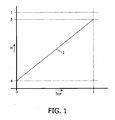
- Figure 1 is a graph schematically illustrating a transmission characteristic of a pixel, for instance an LCD cell.
- the horizontal axis represents a control signal S CP , ranging from 0 for minimum transmission to 1 for maximum transmission.
- the vertical axis represents a transmission ratio H of the pixel, ranging from 0 for perfectly blocking to 1 for 100% transmission.
- the characteristic line 1 is shown as a straight line, but this is not essential.
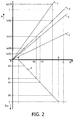
- Figure 2 is a graph schematically illustrating backlight dimming.
- the vertical axis downwards represents the control signal S CP
- the horizontal axis represents the transmission ratio H of the pixel, so that quadrant IV of this graph corresponds to the graph of Figure 1 .
- the vertical axis upwards represents the amount of light I P emanating from the pixel, also indicated as pixel intensity (normalized on the nominal backlight intensity). It is assumed that the pixel intensity I P obeys the above formula (1).
- a certain nominal backlight intensity I BL represented by line 2
- the transmission ratio H of the pixel has a certain value H1
- the pixel intensity I P has a certain value I P (x).
- the same value I P (x) is achieved if the backlight intensity is reduced (indicated by line 3) and the pixel control signal S CP is suitably increased to an increased value S2, in which case the transmission ratio H of the pixel has an increased value H2.
- Backlight dimming can for instance be performed by driving a backlight lamp with a duty cycle less than 1.
- Backlight boosting can for instance simply be implemented if the nominal power setting of a backlight lamp corresponds to a duty cycle less than 1: in that case, the duty cycle can be increased. If, in order to improve the display performance in the case of moving images, a backlight lamp is normally driven at a duty cycle of 30%, a boost factor of over 300% is available.
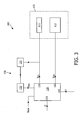
- the controller 120 has a light control output 121 coupled to the backlight 111, for communicating lamp control signals S CL to the backlight 111, and has a pixel control output 122 coupled to the display screen 112, for communicating pixel control signals S CP to the display screen 112.
- the controller 120 has an image input 123 for receiving image data D (video signals), and has a user control input 124 for receiving user control signals U. With the lamp control signals S CL , the controller 120 controls the power setting of to the backlight 111; it is noted that the intensity or brightness of the backlight 111 is proportional to the lamp power in a good approximation.
- the function that describes the relationship between S CL (A) and S CL (D) is a continuous function.
- Such path may be a straight line itself.
- such path is a curved path of which, in points P and Q, the end portions have the same direction as lines 51 and 52, respectively.
- the exact shape of this curved path is not essential, but it is preferred that it is a smooth shape.
- the function that describes the relationship between S CL (A) and S CL (D) between S CL (1) and S CL (2) has a second derivative that is always negative.
- Figure 5B illustrates the situation at a later time t2.
- the calculated lamp control signal S CL (D) has a certain relatively high value S CL (D,t2), although (in the example) lower than the first transition value S CL (1).
- the corresponding actually outputted control signal S CL (A,t2) is higher than S CL (A,t1) and is even higher than S REF : the backlight is boosted.
- Figure 5E illustrates that a steady state is reached when the actually outputted control signal S CL (A) is equal to the average S AV .
- the average S AV will be close to but lower than S REF .
- the power consumed by the backlight does not exceed a predetermined power rating corresponding to S REF .
Landscapes
- Engineering & Computer Science (AREA)
- Physics & Mathematics (AREA)
- General Physics & Mathematics (AREA)
- Theoretical Computer Science (AREA)
- Computer Hardware Design (AREA)
- Crystallography & Structural Chemistry (AREA)
- Chemical & Material Sciences (AREA)
- Nonlinear Science (AREA)
- Mathematical Physics (AREA)
- Optics & Photonics (AREA)
- Liquid Crystal Display Device Control (AREA)
- Control Of Indicators Other Than Cathode Ray Tubes (AREA)
- Devices For Indicating Variable Information By Combining Individual Elements (AREA)
- Liquid Crystal (AREA)
Abstract
Description
- The present invention relates in general to a method and device for driving an image display apparatus, such as for instance in a television, a monitor, etc.
- In general, the invention can be applied to several types of image display apparatus having a backlight. In the following, the invention will be described for an image display device of the LCD type, but it is to be noted that it is not intended to restrict the invention to LCD image display devices.
- In an image display device, an image consists of a large number of image points, each having a specific grey value or color and a specific brightness. In a specific class of image display devices, a viewer is watching a display screen behind which a light source is arranged, the so-called backlight. The display screen comprises a plurality of pixels which can be controlled to pass light or to block light. In a specific embodiment, a pixel is implemented as a liquid crystal cell. A controller receives a video signal with image data, and on the basis of these image data it generates control signals for the liquid crystal cells. In the following, a control signal for pixel cells will be indicated as SCP, and it will be assumed to have a
minimum value 0 and amaximum value 1. - The image data can range from perfect black to perfect white. The image data are translated by the controller to a certain value for the control signal SCP. In the case of perfect black, the brightness data in de video signal will be assumed to have a
minimum value 0. It is noted that, in response to receiving a control signal SCP = 0, the pixel cell should block all light from the backlight. In practice, however, a pixel cell will always "leak" to some extent. In the case of perfect white, the brightness data in de video signal will be assumed to have amaximum value 1. It is noted that, in response to receiving a control signal SCP = 1, the pixel cell should pass all light from the backlight. In practice, however, a pixel cell will always reflect and/or absorb to some extent. So, generally speaking, the transmission rate of a pixel cell, indicated as H, will range from a minimum value α to a maximum value β, wherein 0 < α < β < 1. - In an actual image, the darkest portions may be lighter-than-black and the brightest portions may be darker-than-white. Thus, the transmission rate for all pixels of the image will be in a range from α* to β*, with α<α*<β*<β. The values α* en β* determine the contrast of the image: a high contrast ratio means that the distance between α* and β* is as large as possible.
- Apart from the actual value of the transmission rate H, the amount of light IP emanating from a pixel, as viewed by the viewer, depends on the brightness of the backlight, in other words the intensity IBL of the light generated by the backlight. This might be expressed in a formula as follows:

- Thus, with a certain setting of the intensity IBL of the backlight, the brightness IP of a pixel can range from α·IBL to β·IBL.
- Under certain circumstances, it may be desirable to increase the light output. This may for instance be the case if the level of the ambient light is relatively high. Increasing the light output may be done by shifting the range [α*,β*] to higher values, or at least by shifting the upper limit β* of this range to higher values.
- On the other hand, under certain other certain circumstances, it may be desirable to decrease the light output. This may for instance be the case if the level of the ambient light is relatively low. Decreasing the light output may be done by shifting the range [α*,β*] to lower values, or at least by shifting the lower limit α* of this range to lower values.
- However, increasing or decreasing the light output can also be achieved by increasing or decreasing the intensity IBL of the backlight.
- From
formula 1, it follows that the same pixel brightness IP can be achieved for different settings of the brightness IBL of the backlight. If the brightness IBL of the backlight is multiplied by a certain factor X, and simultaneously the transfer rate H of a pixel cell is divided by the same factor X, the resulting product (X·IBL)·(H/X) = IP. This fact is utilized in backlight boosting and backlight dimming. - In the case of backlight boosting, the intensity IBL of the backlight is increased. This can be used to enhance white parts of an image. By increasing the backlight intensity IBL, those parts appear to be "better white" for the viewer. In grey parts of the image, the grey value can be maintained by simultaneously reducing the control signal SCP for the pixel cells, so that the pixels cells pass less light.
- In the case of backlight dimming, the brightness IBL of the backlight is decreased. This can be used to enhance black parts of an image. By decreasing the backlight intensity IBL, those parts appear to be "better black" for the viewer. In grey parts of the image, the grey value can be maintained by simultaneously increasing the control signal SCP for the pixel cells, so that the pixels cells pass more light.
- By alternating backlight boosting and backlight dimming, the overall contrast ratio of the display device can be enhanced, and energy can be saved.
- An image display device is designed for a certain nominal setting of the backlight light source. In this nominal setting, the backlight light source consumes a certain amount of power, and consequently it generates a certain amount of heat; the image display device is designed to handle this amount of heat. It should be clear that changing the contrast range [α*,β*] of the transmission rate of the screen pixels does not change the power consumption of the backlight. When using backlight dimming, energy is saved, but when using backlight boosting, the backlight light source produces more heat than the image display device is designed to handle. If this situation continues for a prolonged amount of time, the apparatus may become too hot. This problem might be mitigated by using additional cooling means, but this would add to the hardware costs and the energy bill of the apparatus.
- Document
WO-2005/119639 discloses a display device with a backlight, in which the intensity of the backlight is dimmed depending on the image content. The document further discloses that the light source may be limited depending on an average power which may be measured by taking into account actual and historical lamp operating conditions. - The present invention proposes a method for driving an image display device using backlight dimming and backlight boosting such that, on average, the power consumed by the backlight does not exceed a predetermined power rating. In darker scenes, the backlight is dimmed and the display control signals are increased. In very bright scenes, the backlight can temporarily be boosted.
- The predetermined power setting may be equal to the nominal power setting; in that case, brighter images are achieved. However, the predetermined power setting may also be lower than the nominal power setting; in that case, an overall power saving for the display apparatus is achieved.
- Backlight dimming saves energy, but backlight boosting spends more energy. In order not to exceed the predetermined average, it is only possible to perform backlight boosting if it is preceded by a period of backlight dimming. It might be said that backlight dimming provides an energy reserve that can be consumed to perform backlight boosting. However, such reserve is limited. The present invention provides a method for backlight boosting which uses the energy reserve in an efficient manner and, when the energy reserve gets exhausted, reduces the excess energy consumption in an effective manner.
- These and other aspects, features and advantages of the present invention will be further explained by the following description with reference to the drawings, in which same reference numerals indicate same or similar parts, and in which:
-
Figure 1 schematically illustrates a transmission characteristic of a pixel; -
Figure 2 schematically illustrates backlight dimming; -
Figure 3 is a block diagram schematically illustrating a display apparatus; -
Figure 4 is a graph comparable toFigure 2 , also including an apparatus characteristic; -
Figures 5A-E are graphs illustrating a backlight dimming characteristic of a controller of the apparatus ofFigure 3 . -
Figure 1 is a graph schematically illustrating a transmission characteristic of a pixel, for instance an LCD cell. The horizontal axis represents a control signal SCP, ranging from 0 for minimum transmission to 1 for maximum transmission. The vertical axis represents a transmission ratio H of the pixel, ranging from 0 for perfectly blocking to 1 for 100% transmission.Line 1 shows that for control signal SCP = 0, the transmission ratio H(0) = α>0, indicating that the minimum transmission of a pixel is always somewhat larger than zero. Further,line 1 shows that for control signal SCP = 1, the transmission ratio H(1) = β<1, indicating that the maximum transmission of a pixel is always less than 100%. Thecharacteristic line 1 is shown as a straight line, but this is not essential. -
Figure 2 is a graph schematically illustrating backlight dimming. The vertical axis downwards represents the control signal SCP, and the horizontal axis represents the transmission ratio H of the pixel, so that quadrant IV of this graph corresponds to the graph ofFigure 1 . The vertical axis upwards represents the amount of light IP emanating from the pixel, also indicated as pixel intensity (normalized on the nominal backlight intensity). It is assumed that the pixel intensity IP obeys the above formula (1). Thus, at a certain nominal backlight intensity IBL, represented byline 2, if the pixel control signal SCP has a certain value S1, the transmission ratio H of the pixel has a certain value H1 and the pixel intensity IP has a certain value IP(x). The same value IP(x) is achieved if the backlight intensity is reduced (indicated by line 3) and the pixel control signal SCP is suitably increased to an increased value S2, in which case the transmission ratio H of the pixel has an increased value H2. - In
Figure 2 , it can also be seen that, if the pixel control signal SCP is maintained, reducing the backlight intensity causes a reduction of the pixel intensity IP, which particularly can be used to enhance "black" performance. Assume a dark scene, associated with a certain low value S4 of the pixel control signal SCP. With the nominal backlight intensity IBL (line 2), the pixel intensity IP has a relatively high value IP(4). With reduced backlight intensity IBL (line 5), the pixel intensity IP has a substantially lower value IP(5). - Conversely, backlight boosting results in higher pixel intensity IP when the pixel control signal SCP is maintained, which can be used to enhance "white" performance. Assume a bright scene, associated with a certain high value S6 of the pixel control signal SCP. With the nominal backlight intensity IBL (line 2), the pixel intensity IP has a relatively low value IP(6). With increased backlight intensity IBL (line 7), the pixel intensity IP has a substantially higher value IP(7).
- It is noted that backlight boosting and backlight dimming are known per se. Backlight dimming can for instance be performed by driving a backlight lamp with a duty cycle less than 1. Backlight boosting can for instance simply be implemented if the nominal power setting of a backlight lamp corresponds to a duty cycle less than 1: in that case, the duty cycle can be increased. If, in order to improve the display performance in the case of moving images, a backlight lamp is normally driven at a duty cycle of 30%, a boost factor of over 300% is available.
-
Figure 3 is a block diagram schematically illustrating adisplay apparatus 100, comprising adisplay device 110 and acontroller 120. Thedisplay device 110 comprises at least onebacklight lamp 111 and adisplay screen 112. It is noted that display devices with backlight are known per se. The backlight lamp may for instance be implemented as an array of fluorescent tube, or as an array of LEDs. The display screen may for instance be implemented as an array of LCD cells, or any other type of light valve. - The
controller 120 has alight control output 121 coupled to thebacklight 111, for communicating lamp control signals SCL to thebacklight 111, and has apixel control output 122 coupled to thedisplay screen 112, for communicating pixel control signals SCP to thedisplay screen 112. Thecontroller 120 has animage input 123 for receiving image data D (video signals), and has auser control input 124 for receiving user control signals U. With the lamp control signals SCL, thecontroller 120 controls the power setting of to thebacklight 111; it is noted that the intensity or brightness of thebacklight 111 is proportional to the lamp power in a good approximation. -
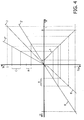
Figure 4 is a graph comparable toFigure 2 , but having added a left-hand horizontal axis representing image data D, wherein D=0 represents perfect black and D=1 represents perfect white. Aline 8 represents a setting of brightness and contrast. If a scene is relatively dark, its pixel data will have values relatively close to zero (range A), resulting, with the nominal backlight intensity IBL (line 2), in relatively low level pixel intensity (range B). In such case, thecontroller 120 may reduce its lamp control signals SCL (line 2') and simultaneously increase its pixel control signals SCP (line 8') to achieve a reduction in power consumption while maintaining the image brightness. It should be clear that backlight dimming in this way is only possible in the case of relatively dark scenes, so it depends on the image contents. - On the other hand, if a scene is relatively bright, the
controller 120 will try to increase the brightness of the backlight by increasing its lamp control signals SCL (line 2"), resulting in a wider area of higher pixel intensity (range C). As mentioned above, a problem may then be that the average power of the backlight becomes too high. - The solution to this problem proposed by the present invention is described below.
- According to a first aspect of the present invention, the
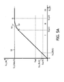
controller 120 sets a maximum to the backlight brightness, i.e. a maximum of the backlight power. This maximum, that will be indicated as IBL(max), corresponds to a maximum SCL(max) of the lamp control signals SCL to be outputted at thelight control output 121. This is illustrated inFigure 5 , which is a graph illustrating a characteristic of thecontroller 120. The horizontal axis represents the calculated lamp control signals SCL(D) as calculated by thecontroller 120 on the basis of the content of the data signals D and the user setting U alone. It is noted that the user setting U may be considered to be constant, but the content of the data signals D changes dynamically with time. The vertical axis represents the actually outputted lamp control signals SCL(A). The graph ofFigure 5A shows astraight line 51 representing the relationship SCL(A) = ξ·4-SCL(D), wherein ξ is a factor which, by way of preferred example, in the following will be taken to be equal to 1. The graph ofFigure 5A further shows ahorizontal line 52 representing the limit value SCL(max).Curve 53 illustrates the behavior of thecontroller 120. For relatively low values of the calculated control signals SCL(D), thecontroller 120 sets its output lamp control signals SCL(A) to be equal to the lamp control signals SCL(D) as calculated on the basis of the data content alone: in this region I, curve 53 followsline 51. - If the calculated control signals SCL(D) exceed the maximum value SCL(max), the
controller 120 sets its output lamp control signals SCL(A) to be equal to the maximum value SCL(max); in this region III,curve 53 followsline 52. - It is possible that curve 53 follows
lines curve 53 in the transition region II.Curve 53 followsline 51 between SCL(D) = 0 and SCL(D) = SCL(1), indicated by a point P, wherein SCL(1) is a first transition value lower than the maximum value SCL(max).Curve 53 followsline 52 for SCL(D) ≥ SCL(2), indicated by a point Q, wherein SCL(2) is a second transition value higher than the maximum value SCL(max). Between SCL(1) and SCL(2),curve 53 follows a path connecting points P and Q. Thus, the function that describes the relationship between SCL(A) and SCL(D) is a continuous function. Such path may be a straight line itself. Preferably, and as illustrated, such path is a curved path of which, in points P and Q, the end portions have the same direction aslines - The transition points P and Q may be calculated from the maximum value SCL(max) in several ways. It is possible that the transition values are calculated according to

- It is also possible that the transition values are calculated according to

- According to a second aspect of the present invention, the
controller 120 is provided with afeedback loop 130 comprising apower calculator 131 and anaverage calculator 132. Thepower calculator 131 has an input receiving the actual lamp control signals SCL(A) outputted by thecontroller 120, and is designed to calculate a value that is proportional to the power consumed by thebacklight 111. Alternatively, it could be possible to actually measure the power consumption by thebacklight 111, but that is more complicated. Theaverage calculator 132 calculates a time-average of the power-representing value as calculated by thepower calculator 131, and provides the result as an average signal SAV to thecontroller 120 at its power average input 126. The time constant of theaverage calculator 132 may be set in relationship with the warming-up and cooling-down properties of thedisplay device 110; in general, theaverage calculator 132 may calculate the average over a time period in the order of several minutes. - In a relatively simple embodiment, the power consumed by the
backlight 111 is proportional to the lamp control signals SCL(A); in that case, a separate power calculator may be omitted, and theaverage calculator 132 may simply calculate the time-average of the lamp control signals SCL(A). It is noted that circuitry or software for calculating a time-average are known per se. - According to a third aspect of the present invention, the
controller 120 compares the average signal SAV with a predetermined reference value SREF, received at a reference input 125. The reference value SREF may be stored in a memory (not shown) associated with the controller. Thecontroller 120 sets the maximum value SCL(max) proportional to the difference (SREF - SAV): if the average signal SAV becomes smaller, the maximum value SCL(max) increases. Ultimately, the maximum value SCL(max) may be higher than the practical range of backlight settings. If the average signal SAV rises, thecontroller 120 decreases the maximum value SCL(max). - This is illustrated in an exaggerated manner in
Figures 5A-E . -
Figure 5A illustrates a situation at a certain time t1. An assumed value for the reference value SREF is indicated. Assume that in this situation the average signal SAV(t1) is substantially lower than the reference value SREF, meaning that in the recent history the power consumption has been relatively low, i.e. a recent history of backlight dimming. Assume further that the calculated lamp control signal SCL(D) has a certain relatively low value SCL(D,t1), and that the actually outputted control signal SCL(A) has a certain value SCL(A,t1) close to the average value SAV(t1). Because the average value SAV(t1) is currently substantially lower than the reference value SREF, the maximum value SCL(max) is high. -
Figure 5B illustrates the situation at a later time t2. Assume a bright scene, so that the calculated lamp control signal SCL(D) has a certain relatively high value SCL(D,t2), although (in the example) lower than the first transition value SCL(1). The corresponding actually outputted control signal SCL(A,t2) is higher than SCL(A,t1) and is even higher than SREF: the backlight is boosted. - Because the actually outputted control signal SCL(A,t2) is higher than SAV(t2), the average SAV is increasing (arrow X1), and consequently the maximum value SCL(max) is decreasing (arrow X2).
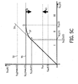
Figure 5C illustrates the situation at a later time t3. It is assumed that the calculated lamp control signal SCL(D,t3) on time t3 is equal to SCL(D,t2).Figure 5C illustrates that the average value SAV(t3) on time t3 has increased with respect to SAV(t2), but it is still lower than the reference value SREF. The decreased maximum value SCL(max,t3) is indicated by ahorizontal line 56 lower than line 52 (shown dotted inFigure 5C ), and the resulting controller characteristic is shown by acurve 57. It is noted that, with the decreasing maximum value SCL(max), also the first and second transition values SCL(1) and SCL(2) have decreased. InFigure 5C , the calculated lamp control signal SCL(D,t3) is still lower than the first transition value SCL(1), so SCL(A,t3) is equal to SCL(A,t2). - Because the actually outputted control signal SCL(A) is still higher than SAV, the average SAV is still increasing (arrow X3), and consequently the maximum value SCL(max) is still decreasing (arrow X4).
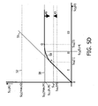
Figure 5D illustrates the situation at a still later time t4. The average value SAV(t4) on time t4 has increased with respect to SAV(t3), but it is still lower than the reference value SREF. The decreased maximum value SCL(max,t4) is indicated by ahorizontal line 58, and the resulting controller characteristic is shown by acurve 59. It is assumed that the calculated lamp control signal SCL(D,t4) on time t4 is still equal to SCL(D,t2). The first transition value SCL(1) is now lower than the calculated lamp control signal SCL(D,t4), and consequently the actually outputted control signal SCL(A,t4) is lower than SCL(A,t3). - Although the actually outputted control signal SCL(A,t4) is reduced with respect to SCL(A,t3), it is still higher than SAV, so the average SAV is still increasing (arrow X5), and consequently the maximum value SCL(max) is still decreasing (arrow X6). It should be clear that, with the decreasing maximum value SCL(max), also the actually outputted control signal SCL(A,t4) is decreasing, so that the rate of increase of the average SAV is decreasing.
-
Figure 5E illustrates that a steady state is reached when the actually outputted control signal SCL(A) is equal to the average SAV. When that happens, the average SAV will be close to but lower than SREF. Thus, on average, the power consumed by the backlight does not exceed a predetermined power rating corresponding to SREF. - The predetermined reference value SREF can be a design parameter, or a parameter that can be set by the user. In one embodiment, the predetermined reference value SREF can be equal to the original nominal design power of the backlight, indicated as 100%. However, in another embodiment the predetermined reference value SREF can be set to a lower value, for instance 70%. In that case, occasional backlight boosting to values of 100% or more can be combined with the guarantee that the overall power consumption is reduced. Of course, the amount of backlight boost, in terms of percentage or duration, depends on the history of dark scenes as well as on the setting of the reference value SREF, as should be clear to a person skilled in the art.
- When the above-mentioned steady state is reached, i.e. when the actually outputted control signal SCL(A) is equal to the average SAV, backlight boosting is no longer possible. It can be said that the energy reserve is exhausted. Only when further dark scenes happen, the backlight is dimmed, as explained earlier, so that the average power consumption decreases. Simultaneously, the maximum value SCL(max) is increased, and backlight boosting becomes possible again. The lower the average power consumed over the recent time period is at the moment when backlight boosting is requested, the further the backlight intensity can be increased, or an the longer the increased intensity can be maintained.
- By decreasing the maximum value SCL(max), instead of simply reducing the actual backlight intensity, the result is that the boosting of the brightest scenes is limited first, whereas the less bright scenes can be boosted longer.
- It should be clear to a person skilled in the art that the present invention is not limited to the exemplary embodiments discussed above, but that several variations and modifications are possible within the protective scope of the invention as defined in the appending claims. For instance, in
Figure 3 thefeedback loop 130 is shown as being external to thecontroller 120, but thefeedback loop 130 may alternatively be integral part of thecontroller 120. - It is noted that amending the maximum value SCL(max) can be done at predetermined time intervals, for instance 60 times per second, or continuously.
- In the above, it was mentioned that the
controller 120 sets the maximum value SCL(max) proportional to the difference (SREF - SAV). The function that describes the relationship between SCL(max) and the difference (SREF - SAV) may be a linear, first order function. However, this function may also comprise second order or higher order terms. The function may also have a zero-th order term unequal to zero. - In the above, the present invention has been explained with reference to block diagrams, which illustrate functional blocks of the device according to the present invention. It is to be understood that one or more of these functional blocks may be implemented in hardware, where the function of such functional block is performed by individual hardware components, but it is also possible that one or more of these functional blocks are implemented in software, so that the function of such functional block is performed by one or more program lines of a computer program or a programmable device such as a microprocessor, microcontroller, digital signal processor, etc.
Claims (9)
- Method for driving an image display device (110) comprising at least one backlight lamp (111) and a display screen (112), the method comprising the steps of:- receiving an image data signal (D);- on the basis of the image data signal (D), calculating a content-related backlight control signal (SCL(D)) for the backlight lamp (111) for setting the intensity of the backlight;- generating an average signal (SAV) that represents a time-average of the power consumed by the backlight lamp (111),- comparing the average signal (SAV) with a reference signal (SREF);- on the basis of the calculated content-related backlight control signal (SCL(D)), taking into account the result of the said comparison, generating an actual backlight control signal (SCL(A)) for the backlight lamp (111); characterized in that the average signal (SAV) is generated from the actual backlight control signal (SCL(A)) the average being calculated over a time period in the order of several minutes, and the step of generating the actual backlight control signal (SCL(A)) comprises the steps of:-- setting a maximum value (SCL(max)) for the actual backlight control signal (SCL(A));-- defining a first transition value (SCL(1)) and a second transition value (SCL(2)) higher than or equal to the first transition value (SCL(1));-- generating the actual backlight control signal (SCL(A)) equal to ξ times the calculated content-related backlight control signal (SCL(D)) if the calculated content-related backlight control signal (SCL(D)) is less than the first transition value (SCL(1)), wherein ξ is a predetermined factor;-- generating the actual backlight control signal (SCL(A)) equal to the maximum value (SCL(max)) if the calculated content-related backlight control signal (SCL(D)) is higher than the second transition value (SCL(2));-- generating the actual backlight control signal (SCLA)) to have a value lower than ξ times the calculated content-related backlight control signal (SCL(D)) and lower than the maximum value (SCL(max)) if the calculated content-related backlight control signal (SCL(D)) is between the first transition value (SCL(1)) and the second transition value (SCL(2)); wherein the maximum value (SCL(max)) is proportional to the difference (SREF-SAV) between the reference signal and the average signal.
- Method according to claim 1, wherein, if the image data signal (D) represents dark scenes, the backlight is dimmed, whereas if the image data signal (D) represents bright scenes, the backlight is boosted;
wherein the amount of boost is limited such that the time-average of the power consumed by the backlight lamp (111) does not exceed a predetermined level. - Method according to claim 1, wherein ξ is equal to 1.
- Method according to claim 1, wherein, between the first transition value (SCL(1)) and the second transition value (SCL(2)), the function that describes the relationship between the actual backlight control signal (SCL(A)) and the calculated content-related backlight control signal (SCL(D)) has a second derivative that is always negative.
- Method according to claim 1, wherein the function that describes the relationship between the actual backlight control signal (SCL(A)) and the calculated content-related backlight control signal (SCL(D)) is a continuous function.
- Method according to claim 1, wherein the function that describes the relationship between the actual backlight control signal (SCL(A)) and the calculated content-related backlight control signal (SCL(D)) can be continuously differentiated.
- Method according to claim 1, wherein, at a certain time (t1), the average signal (SAV) represents the power actually consumed by the backlight lamp (111) averaged over a time period with a predetermined duration immediately before said time (t1).
- Method according to claim 1, further comprising the steps of:- on the basis of the image data signal (D), generating a screen control signal (SCP) for the display screen (112);- if the screen control signals (SCP) of an image are within a range lower than a maximally possible value, increasing the screen control signals (SCP) while decreasing the calculated backlight control signal (SCL(D)).
- Display apparatus (100), comprising an image display device (110) including at least one backlight lamp (111) and a display screen (112), the apparatus comprising a controller (120) having:- a light output (121) coupled to the backlight lamp (111) for providing an actual backlight control signal (SCL(A)),- a pixel control output (122) coupled to the display screen (112) for providing pixel control signals (SCP);- an image input (123) for receiving an image data signal (D),- a reference input (125) for receiving a reference value (SREF),- a power average input (126) for receiving an average signal (SAV);the apparatus further comprising a feedback loop (130) having its input coupled to the light output (121) of the controller (120) and having its output coupled to the power average input (126) of the controller (120), the feedback loop including means (131, 132) for calculating a signal (SAV) representing a time-average of the power consumption by the backlight (111); wherein the controller is designed to execute the method of any of claims 1-8.
Priority Applications (1)
| Application Number | Priority Date | Filing Date | Title |
|---|---|---|---|
| EP07735663A EP2024958B1 (en) | 2006-05-15 | 2007-04-26 | Method and device for driving an image display apparatus |
Applications Claiming Priority (3)
| Application Number | Priority Date | Filing Date | Title |
|---|---|---|---|
| EP06113910 | 2006-05-15 | ||
| PCT/IB2007/051544 WO2007132370A1 (en) | 2006-05-15 | 2007-04-26 | Method and device for driving an image display apparatus |
| EP07735663A EP2024958B1 (en) | 2006-05-15 | 2007-04-26 | Method and device for driving an image display apparatus |
Publications (2)
| Publication Number | Publication Date |
|---|---|
| EP2024958A1 EP2024958A1 (en) | 2009-02-18 |
| EP2024958B1 true EP2024958B1 (en) | 2011-11-30 |
Family
ID=38508840
Family Applications (1)
| Application Number | Title | Priority Date | Filing Date |
|---|---|---|---|
| EP07735663A Active EP2024958B1 (en) | 2006-05-15 | 2007-04-26 | Method and device for driving an image display apparatus |
Country Status (9)
| Country | Link |
|---|---|
| US (1) | US8203522B2 (en) |
| EP (1) | EP2024958B1 (en) |
| JP (1) | JP5272227B2 (en) |
| KR (1) | KR101469537B1 (en) |
| CN (1) | CN101449316B (en) |
| AT (1) | ATE535901T1 (en) |
| ES (1) | ES2377577T3 (en) |
| TW (1) | TW200811825A (en) |
| WO (1) | WO2007132370A1 (en) |
Families Citing this family (7)
| Publication number | Priority date | Publication date | Assignee | Title |
|---|---|---|---|---|
| RU2496155C2 (en) * | 2008-10-10 | 2013-10-20 | Шарп Кабусики Кайся | Power control method for light-emitting device for image display, light-emitting device for image display, display device and television receiver |
| US8522059B2 (en) * | 2009-11-24 | 2013-08-27 | Hewlett-Packard Development Company, L.P. | Display panel power prediction |
| JP5460435B2 (en) | 2010-04-09 | 2014-04-02 | 日立コンシューマエレクトロニクス株式会社 | Image display device and control method of image display device |
| CN102339590A (en) * | 2010-07-27 | 2012-02-01 | 英华达(上海)科技有限公司 | Power-saving device and method for electronic system |
| US8730274B2 (en) * | 2011-02-25 | 2014-05-20 | Synaptics Incorporated | Backlight dimming ratio based dynamic knee point determination of soft clipping |
| US10582740B2 (en) | 2016-02-26 | 2020-03-10 | Nike, Inc. | Method of customizing stability in articles of footwear |
| CN110288935B (en) * | 2019-06-26 | 2022-07-12 | 广州小鹏汽车科技有限公司 | Monitoring method and monitoring device for vehicle-mounted liquid crystal display backlight source |
Family Cites Families (13)
| Publication number | Priority date | Publication date | Assignee | Title |
|---|---|---|---|---|
| US7088335B2 (en) * | 1999-04-28 | 2006-08-08 | Novus Partners Llc | Methods and apparatus for ultra-violet stimulated displays |
| TWI285872B (en) * | 1999-05-10 | 2007-08-21 | Matsushita Electric Industrial Co Ltd | Image display device and method for displaying image |
| US6377236B1 (en) | 1999-07-29 | 2002-04-23 | Hewlett-Packard Company | Method of illuminating a light valve with improved light throughput and color balance correction |
| EP1367558A3 (en) * | 2002-05-29 | 2008-08-27 | Matsushita Electric Industrial Co., Ltd. | Image display method and apparatus comprising luminance adjustment of a light source |
| JP2004177547A (en) * | 2002-11-26 | 2004-06-24 | Mitsubishi Electric Corp | Control method of backlight for liquid crystal display and control device therefor |
| US7176878B2 (en) | 2002-12-11 | 2007-02-13 | Nvidia Corporation | Backlight dimming and LCD amplitude boost |
| JP4927311B2 (en) | 2003-08-27 | 2012-05-09 | 株式会社日立製作所 | VIDEO DISPLAY DEVICE, DISPLAY UNIT DRIVE CIRCUIT USED FOR THE SAME |
| WO2005093703A1 (en) | 2004-03-26 | 2005-10-06 | Koninklijke Philips Electronics N.V. | Display device comprising an adjustable light source |
| EP1747547B1 (en) | 2004-05-11 | 2009-07-22 | Nxp B.V. | Method for processing image data |
| US20070216616A1 (en) * | 2004-06-01 | 2007-09-20 | Koninklijke Philips Electronics, N.V. | Display Device Comprising A Light Source |
| US7982707B2 (en) * | 2004-12-02 | 2011-07-19 | Sharp Laboratories Of America, Inc. | Methods and systems for generating and applying image tone scale adjustments |
| WO2007029420A1 (en) * | 2005-09-08 | 2007-03-15 | Sharp Kabushiki Kaisha | Image display device |
| US9093041B2 (en) * | 2005-11-28 | 2015-07-28 | Honeywell International Inc. | Backlight variation compensated display |
-
2007
- 2007-04-26 ES ES07735663T patent/ES2377577T3/en active Active
- 2007-04-26 JP JP2009510572A patent/JP5272227B2/en not_active Expired - Fee Related
- 2007-04-26 KR KR1020087030396A patent/KR101469537B1/en not_active Expired - Fee Related
- 2007-04-26 AT AT07735663T patent/ATE535901T1/en active
- 2007-04-26 EP EP07735663A patent/EP2024958B1/en active Active
- 2007-04-26 CN CN2007800177847A patent/CN101449316B/en active Active
- 2007-04-26 US US12/300,841 patent/US8203522B2/en active Active
- 2007-04-26 WO PCT/IB2007/051544 patent/WO2007132370A1/en not_active Ceased
- 2007-05-11 TW TW096116902A patent/TW200811825A/en unknown
Non-Patent Citations (1)
| Title |
|---|
| STESSEN PHILIPS APPLIED TECHNOLOGIES-DIGITAL SYSTEMS LAB-NL 5616 LW EINDHOVEN-THE NETHERLANDS J G R VAN MOURIK PHILIPS CONSUMER EL: "26.4: Algorithm for Contrast Reserve, Backlight Dimming, and Backlight Boosting on LCD", SID 2006, 2006 SID INTERNATIONAL SYMPOSIUM, SOCIETY FOR INFORMATION DISPLAY, vol. XXXVII, 24 May 2005 (2005-05-24), pages 1249 - 1251, XP007012707, ISSN: 0006-966X * |
Also Published As
| Publication number | Publication date |
|---|---|
| CN101449316B (en) | 2013-02-06 |
| US20090115766A1 (en) | 2009-05-07 |
| ES2377577T3 (en) | 2012-03-29 |
| TW200811825A (en) | 2008-03-01 |
| EP2024958A1 (en) | 2009-02-18 |
| ATE535901T1 (en) | 2011-12-15 |
| JP2009537856A (en) | 2009-10-29 |
| US8203522B2 (en) | 2012-06-19 |
| CN101449316A (en) | 2009-06-03 |
| KR20090018633A (en) | 2009-02-20 |
| KR101469537B1 (en) | 2014-12-05 |
| JP5272227B2 (en) | 2013-08-28 |
| WO2007132370A1 (en) | 2007-11-22 |
Similar Documents
| Publication | Publication Date | Title |
|---|---|---|
| EP2024958B1 (en) | Method and device for driving an image display apparatus | |
| US8860657B2 (en) | Liquid crystal display backlight control | |
| US7742032B2 (en) | Image adaptation phase-in | |
| US8963826B2 (en) | Video display apparatus including brightness control based on ambient illuminance | |
| CN101393723B (en) | Low-power image display device and method | |
| US20090002563A1 (en) | Light-leakage-correction technique for video playback | |
| EP2043079A2 (en) | Video displaying apparatus with dynamic brightness control of the backlight | |
| WO2011004520A1 (en) | Liquid crystal display device and method for controlling display of liquid crystal display device | |
| CN103430230B (en) | Video display devices | |
| KR101073006B1 (en) | Display device and method for controling brightness of images in display device | |
| EP1698169B1 (en) | Display and control method thereof | |
| EP2094006B1 (en) | Contrast ratio promotion method | |
| Stessen et al. | 26.4: Algorithm for contrast reserve, backlight dimming, and backlight boosting on lcd | |
| JP4987134B1 (en) | Video display device | |
| KR100758981B1 (en) | Backlight unit having a plurality of light emitting elements and control method thereof | |
| KR100467592B1 (en) | Apparatus and method for display | |
| US20250006139A1 (en) | Backlight adjustment technologies | |
| JP2012194559A (en) | Image display | |
| JP2025139777A (en) | Illumination device, display device, and method for controlling illumination device | |
| TW200906168A (en) | Image display device and image display method |
Legal Events
| Date | Code | Title | Description |
|---|---|---|---|
| PUAI | Public reference made under article 153(3) epc to a published international application that has entered the european phase |
Free format text: ORIGINAL CODE: 0009012 |
|
| 17P | Request for examination filed |
Effective date: 20081215 |
|
| AK | Designated contracting states |
Kind code of ref document: A1 Designated state(s): AT BE BG CH CY CZ DE DK EE ES FI FR GB GR HU IE IS IT LI LT LU LV MC MT NL PL PT RO SE SI SK TR |
|
| AX | Request for extension of the european patent |
Extension state: AL BA HR MK RS |
|
| 17Q | First examination report despatched |
Effective date: 20090811 |
|
| GRAP | Despatch of communication of intention to grant a patent |
Free format text: ORIGINAL CODE: EPIDOSNIGR1 |
|
| DAX | Request for extension of the european patent (deleted) | ||
| GRAS | Grant fee paid |
Free format text: ORIGINAL CODE: EPIDOSNIGR3 |
|
| GRAA | (expected) grant |
Free format text: ORIGINAL CODE: 0009210 |
|
| AK | Designated contracting states |
Kind code of ref document: B1 Designated state(s): AT BE BG CH CY CZ DE DK EE ES FI FR GB GR HU IE IS IT LI LT LU LV MC MT NL PL PT RO SE SI SK TR |
|
| REG | Reference to a national code |
Ref country code: GB Ref legal event code: FG4D Ref country code: CH Ref legal event code: EP |
|
| REG | Reference to a national code |
Ref country code: IE Ref legal event code: FG4D |
|
| REG | Reference to a national code |
Ref country code: GB Ref legal event code: 746 Effective date: 20111220 |
|
| REG | Reference to a national code |
Ref country code: DE Ref legal event code: R096 Ref document number: 602007019084 Country of ref document: DE Effective date: 20120202 Ref country code: DE Ref legal event code: R084 Ref document number: 602007019084 Country of ref document: DE Effective date: 20111203 |
|
| REG | Reference to a national code |
Ref country code: ES Ref legal event code: GC2A Effective date: 20120224 |
|
| REG | Reference to a national code |
Ref country code: NL Ref legal event code: VDEP Effective date: 20111130 |
|
| REG | Reference to a national code |
Ref country code: ES Ref legal event code: FG2A Ref document number: 2377577 Country of ref document: ES Kind code of ref document: T3 Effective date: 20120329 |
|
| LTIE | Lt: invalidation of european patent or patent extension |
Effective date: 20111130 |
|
| PG25 | Lapsed in a contracting state [announced via postgrant information from national office to epo] |
Ref country code: LT Free format text: LAPSE BECAUSE OF FAILURE TO SUBMIT A TRANSLATION OF THE DESCRIPTION OR TO PAY THE FEE WITHIN THE PRESCRIBED TIME-LIMIT Effective date: 20111130 Ref country code: IS Free format text: LAPSE BECAUSE OF FAILURE TO SUBMIT A TRANSLATION OF THE DESCRIPTION OR TO PAY THE FEE WITHIN THE PRESCRIBED TIME-LIMIT Effective date: 20120330 |
|
| PG25 | Lapsed in a contracting state [announced via postgrant information from national office to epo] |
Ref country code: SI Free format text: LAPSE BECAUSE OF FAILURE TO SUBMIT A TRANSLATION OF THE DESCRIPTION OR TO PAY THE FEE WITHIN THE PRESCRIBED TIME-LIMIT Effective date: 20111130 Ref country code: PT Free format text: LAPSE BECAUSE OF FAILURE TO SUBMIT A TRANSLATION OF THE DESCRIPTION OR TO PAY THE FEE WITHIN THE PRESCRIBED TIME-LIMIT Effective date: 20120330 Ref country code: BE Free format text: LAPSE BECAUSE OF FAILURE TO SUBMIT A TRANSLATION OF THE DESCRIPTION OR TO PAY THE FEE WITHIN THE PRESCRIBED TIME-LIMIT Effective date: 20111130 Ref country code: GR Free format text: LAPSE BECAUSE OF FAILURE TO SUBMIT A TRANSLATION OF THE DESCRIPTION OR TO PAY THE FEE WITHIN THE PRESCRIBED TIME-LIMIT Effective date: 20120301 Ref country code: SE Free format text: LAPSE BECAUSE OF FAILURE TO SUBMIT A TRANSLATION OF THE DESCRIPTION OR TO PAY THE FEE WITHIN THE PRESCRIBED TIME-LIMIT Effective date: 20111130 Ref country code: LV Free format text: LAPSE BECAUSE OF FAILURE TO SUBMIT A TRANSLATION OF THE DESCRIPTION OR TO PAY THE FEE WITHIN THE PRESCRIBED TIME-LIMIT Effective date: 20111130 Ref country code: NL Free format text: LAPSE BECAUSE OF FAILURE TO SUBMIT A TRANSLATION OF THE DESCRIPTION OR TO PAY THE FEE WITHIN THE PRESCRIBED TIME-LIMIT Effective date: 20111130 |
|
| PG25 | Lapsed in a contracting state [announced via postgrant information from national office to epo] |
Ref country code: CY Free format text: LAPSE BECAUSE OF FAILURE TO SUBMIT A TRANSLATION OF THE DESCRIPTION OR TO PAY THE FEE WITHIN THE PRESCRIBED TIME-LIMIT Effective date: 20111130 |
|
| PG25 | Lapsed in a contracting state [announced via postgrant information from national office to epo] |
Ref country code: DK Free format text: LAPSE BECAUSE OF FAILURE TO SUBMIT A TRANSLATION OF THE DESCRIPTION OR TO PAY THE FEE WITHIN THE PRESCRIBED TIME-LIMIT Effective date: 20111130 Ref country code: SK Free format text: LAPSE BECAUSE OF FAILURE TO SUBMIT A TRANSLATION OF THE DESCRIPTION OR TO PAY THE FEE WITHIN THE PRESCRIBED TIME-LIMIT Effective date: 20111130 Ref country code: EE Free format text: LAPSE BECAUSE OF FAILURE TO SUBMIT A TRANSLATION OF THE DESCRIPTION OR TO PAY THE FEE WITHIN THE PRESCRIBED TIME-LIMIT Effective date: 20111130 Ref country code: CZ Free format text: LAPSE BECAUSE OF FAILURE TO SUBMIT A TRANSLATION OF THE DESCRIPTION OR TO PAY THE FEE WITHIN THE PRESCRIBED TIME-LIMIT Effective date: 20111130 Ref country code: BG Free format text: LAPSE BECAUSE OF FAILURE TO SUBMIT A TRANSLATION OF THE DESCRIPTION OR TO PAY THE FEE WITHIN THE PRESCRIBED TIME-LIMIT Effective date: 20120229 |
|
| RAP2 | Party data changed (patent owner data changed or rights of a patent transferred) |
Owner name: TP VISION HOLDING B.V. |
|
| PG25 | Lapsed in a contracting state [announced via postgrant information from national office to epo] |
Ref country code: PL Free format text: LAPSE BECAUSE OF FAILURE TO SUBMIT A TRANSLATION OF THE DESCRIPTION OR TO PAY THE FEE WITHIN THE PRESCRIBED TIME-LIMIT Effective date: 20111130 Ref country code: RO Free format text: LAPSE BECAUSE OF FAILURE TO SUBMIT A TRANSLATION OF THE DESCRIPTION OR TO PAY THE FEE WITHIN THE PRESCRIBED TIME-LIMIT Effective date: 20111130 |
|
| REG | Reference to a national code |
Ref country code: AT Ref legal event code: MK05 Ref document number: 535901 Country of ref document: AT Kind code of ref document: T Effective date: 20111130 |
|
| REG | Reference to a national code |
Ref country code: GB Ref legal event code: 732E Free format text: REGISTERED BETWEEN 20120906 AND 20120912 |
|
| PLBE | No opposition filed within time limit |
Free format text: ORIGINAL CODE: 0009261 |
|
| STAA | Information on the status of an ep patent application or granted ep patent |
Free format text: STATUS: NO OPPOSITION FILED WITHIN TIME LIMIT |
|
| REG | Reference to a national code |
Ref country code: DE Ref legal event code: R119 Ref document number: 602007019084 Country of ref document: DE Ref country code: DE Ref legal event code: R409 Ref document number: 602007019084 Country of ref document: DE |
|
| 26N | No opposition filed |
Effective date: 20120831 |
|
| PG25 | Lapsed in a contracting state [announced via postgrant information from national office to epo] |
Ref country code: MC Free format text: LAPSE BECAUSE OF NON-PAYMENT OF DUE FEES Effective date: 20120430 |
|
| REG | Reference to a national code |
Ref country code: CH Ref legal event code: PL |
|
| REG | Reference to a national code |
Ref country code: DE Ref legal event code: R097 Ref document number: 602007019084 Country of ref document: DE Effective date: 20120831 |
|
| REG | Reference to a national code |
Ref country code: IE Ref legal event code: MM4A |
|
| REG | Reference to a national code |
Ref country code: DE Ref legal event code: R409 Ref document number: 602007019084 Country of ref document: DE |
|
| REG | Reference to a national code |
Ref country code: DE Ref legal event code: R082 Ref document number: 602007019084 Country of ref document: DE Representative=s name: GIPP, THOMAS, DIPL.-ING., DE |
|
| PG25 | Lapsed in a contracting state [announced via postgrant information from national office to epo] |
Ref country code: LI Free format text: LAPSE BECAUSE OF NON-PAYMENT OF DUE FEES Effective date: 20120430 Ref country code: AT Free format text: LAPSE BECAUSE OF FAILURE TO SUBMIT A TRANSLATION OF THE DESCRIPTION OR TO PAY THE FEE WITHIN THE PRESCRIBED TIME-LIMIT Effective date: 20111130 Ref country code: IE Free format text: LAPSE BECAUSE OF NON-PAYMENT OF DUE FEES Effective date: 20120426 Ref country code: CH Free format text: LAPSE BECAUSE OF NON-PAYMENT OF DUE FEES Effective date: 20120430 |
|
| REG | Reference to a national code |
Ref country code: DE Ref legal event code: R082 Ref document number: 602007019084 Country of ref document: DE Representative=s name: GIPP, THOMAS, DIPL.-ING., DE Effective date: 20130130 Ref country code: DE Ref legal event code: R081 Ref document number: 602007019084 Country of ref document: DE Owner name: TP VISION HOLDING B.V., NL Free format text: FORMER OWNER: KONINKLIJKE PHILIPS ELECTRONICS N.V., EINDHOVEN, NL Effective date: 20130130 |
|
| PG25 | Lapsed in a contracting state [announced via postgrant information from national office to epo] |
Ref country code: FI Free format text: LAPSE BECAUSE OF FAILURE TO SUBMIT A TRANSLATION OF THE DESCRIPTION OR TO PAY THE FEE WITHIN THE PRESCRIBED TIME-LIMIT Effective date: 20111130 |
|
| PG25 | Lapsed in a contracting state [announced via postgrant information from national office to epo] |
Ref country code: MT Free format text: LAPSE BECAUSE OF FAILURE TO SUBMIT A TRANSLATION OF THE DESCRIPTION OR TO PAY THE FEE WITHIN THE PRESCRIBED TIME-LIMIT Effective date: 20111130 |
|
| PG25 | Lapsed in a contracting state [announced via postgrant information from national office to epo] |
Ref country code: LU Free format text: LAPSE BECAUSE OF NON-PAYMENT OF DUE FEES Effective date: 20120426 |
|
| PG25 | Lapsed in a contracting state [announced via postgrant information from national office to epo] |
Ref country code: HU Free format text: LAPSE BECAUSE OF FAILURE TO SUBMIT A TRANSLATION OF THE DESCRIPTION OR TO PAY THE FEE WITHIN THE PRESCRIBED TIME-LIMIT Effective date: 20070426 |
|
| REG | Reference to a national code |
Ref country code: FR Ref legal event code: PLFP Year of fee payment: 10 |
|
| PGFP | Annual fee paid to national office [announced via postgrant information from national office to epo] |
Ref country code: ES Payment date: 20160518 Year of fee payment: 10 |
|
| PGFP | Annual fee paid to national office [announced via postgrant information from national office to epo] |
Ref country code: TR Payment date: 20160426 Year of fee payment: 10 |
|
| REG | Reference to a national code |
Ref country code: FR Ref legal event code: PLFP Year of fee payment: 11 |
|
| REG | Reference to a national code |
Ref country code: FR Ref legal event code: PLFP Year of fee payment: 12 |
|
| REG | Reference to a national code |
Ref country code: ES Ref legal event code: FD2A Effective date: 20180705 |
|
| PG25 | Lapsed in a contracting state [announced via postgrant information from national office to epo] |
Ref country code: ES Free format text: LAPSE BECAUSE OF NON-PAYMENT OF DUE FEES Effective date: 20170427 |
|
| PGFP | Annual fee paid to national office [announced via postgrant information from national office to epo] |
Ref country code: GB Payment date: 20190305 Year of fee payment: 13 Ref country code: FR Payment date: 20190305 Year of fee payment: 13 |
|
| PGFP | Annual fee paid to national office [announced via postgrant information from national office to epo] |
Ref country code: IT Payment date: 20190418 Year of fee payment: 13 |
|
| PG25 | Lapsed in a contracting state [announced via postgrant information from national office to epo] |
Ref country code: FR Free format text: LAPSE BECAUSE OF NON-PAYMENT OF DUE FEES Effective date: 20200430 |
|
| GBPC | Gb: european patent ceased through non-payment of renewal fee |
Effective date: 20200426 |
|
| PG25 | Lapsed in a contracting state [announced via postgrant information from national office to epo] |
Ref country code: GB Free format text: LAPSE BECAUSE OF NON-PAYMENT OF DUE FEES Effective date: 20200426 |
|
| PG25 | Lapsed in a contracting state [announced via postgrant information from national office to epo] |
Ref country code: IT Free format text: LAPSE BECAUSE OF NON-PAYMENT OF DUE FEES Effective date: 20200426 |
|
| REG | Reference to a national code |
Ref country code: DE Ref legal event code: R081 Ref document number: 602007019084 Country of ref document: DE Owner name: TOP VICTORY INVESTMENTS LIMITED, KWUN TONG, HK Free format text: FORMER OWNER: TP VISION HOLDING B.V., EINDHOVEN, NL Ref country code: DE Ref legal event code: R082 Ref document number: 602007019084 Country of ref document: DE |
|
| PG25 | Lapsed in a contracting state [announced via postgrant information from national office to epo] |
Ref country code: TR Free format text: LAPSE BECAUSE OF NON-PAYMENT OF DUE FEES Effective date: 20170426 |
|
| PGFP | Annual fee paid to national office [announced via postgrant information from national office to epo] |
Ref country code: DE Payment date: 20250303 Year of fee payment: 19 |