EP2023787B1 - Wet type suction cleaners - Google Patents
Wet type suction cleaners Download PDFInfo
- Publication number
- EP2023787B1 EP2023787B1 EP07733019A EP07733019A EP2023787B1 EP 2023787 B1 EP2023787 B1 EP 2023787B1 EP 07733019 A EP07733019 A EP 07733019A EP 07733019 A EP07733019 A EP 07733019A EP 2023787 B1 EP2023787 B1 EP 2023787B1
- Authority
- EP
- European Patent Office
- Prior art keywords
- housing
- tank
- valve assembly
- float valve
- opening
- Prior art date
- Legal status (The legal status is an assumption and is not a legal conclusion. Google has not performed a legal analysis and makes no representation as to the accuracy of the status listed.)
- Not-in-force
Links
Images
Classifications
-
- A—HUMAN NECESSITIES
- A47—FURNITURE; DOMESTIC ARTICLES OR APPLIANCES; COFFEE MILLS; SPICE MILLS; SUCTION CLEANERS IN GENERAL
- A47L—DOMESTIC WASHING OR CLEANING; SUCTION CLEANERS IN GENERAL
- A47L7/00—Suction cleaners adapted for additional purposes; Tables with suction openings for cleaning purposes; Containers for cleaning articles by suction; Suction cleaners adapted to cleaning of brushes; Suction cleaners adapted to taking-up liquids
- A47L7/0004—Suction cleaners adapted to take up liquids, e.g. wet or dry vacuum cleaners
- A47L7/0023—Recovery tanks
- A47L7/0028—Security means, e.g. float valves or level switches for preventing overflow
-
- A—HUMAN NECESSITIES
- A47—FURNITURE; DOMESTIC ARTICLES OR APPLIANCES; COFFEE MILLS; SPICE MILLS; SUCTION CLEANERS IN GENERAL
- A47L—DOMESTIC WASHING OR CLEANING; SUCTION CLEANERS IN GENERAL
- A47L5/00—Structural features of suction cleaners
-
- A—HUMAN NECESSITIES
- A47—FURNITURE; DOMESTIC ARTICLES OR APPLIANCES; COFFEE MILLS; SPICE MILLS; SUCTION CLEANERS IN GENERAL
- A47L—DOMESTIC WASHING OR CLEANING; SUCTION CLEANERS IN GENERAL
- A47L5/00—Structural features of suction cleaners
- A47L5/12—Structural features of suction cleaners with power-driven air-pumps or air-compressors, e.g. driven by motor vehicle engine vacuum
-
- A—HUMAN NECESSITIES
- A47—FURNITURE; DOMESTIC ARTICLES OR APPLIANCES; COFFEE MILLS; SPICE MILLS; SUCTION CLEANERS IN GENERAL
- A47L—DOMESTIC WASHING OR CLEANING; SUCTION CLEANERS IN GENERAL
- A47L5/00—Structural features of suction cleaners
- A47L5/12—Structural features of suction cleaners with power-driven air-pumps or air-compressors, e.g. driven by motor vehicle engine vacuum
- A47L5/22—Structural features of suction cleaners with power-driven air-pumps or air-compressors, e.g. driven by motor vehicle engine vacuum with rotary fans
-
- A—HUMAN NECESSITIES
- A47—FURNITURE; DOMESTIC ARTICLES OR APPLIANCES; COFFEE MILLS; SPICE MILLS; SUCTION CLEANERS IN GENERAL
- A47L—DOMESTIC WASHING OR CLEANING; SUCTION CLEANERS IN GENERAL
- A47L5/00—Structural features of suction cleaners
- A47L5/12—Structural features of suction cleaners with power-driven air-pumps or air-compressors, e.g. driven by motor vehicle engine vacuum
- A47L5/22—Structural features of suction cleaners with power-driven air-pumps or air-compressors, e.g. driven by motor vehicle engine vacuum with rotary fans
- A47L5/36—Suction cleaners with hose between nozzle and casing; Suction cleaners for fixing on staircases; Suction cleaners for carrying on the back
-
- A—HUMAN NECESSITIES
- A47—FURNITURE; DOMESTIC ARTICLES OR APPLIANCES; COFFEE MILLS; SPICE MILLS; SUCTION CLEANERS IN GENERAL
- A47L—DOMESTIC WASHING OR CLEANING; SUCTION CLEANERS IN GENERAL
- A47L5/00—Structural features of suction cleaners
- A47L5/12—Structural features of suction cleaners with power-driven air-pumps or air-compressors, e.g. driven by motor vehicle engine vacuum
- A47L5/22—Structural features of suction cleaners with power-driven air-pumps or air-compressors, e.g. driven by motor vehicle engine vacuum with rotary fans
- A47L5/36—Suction cleaners with hose between nozzle and casing; Suction cleaners for fixing on staircases; Suction cleaners for carrying on the back
- A47L5/365—Suction cleaners with hose between nozzle and casing; Suction cleaners for fixing on staircases; Suction cleaners for carrying on the back of the vertical type, e.g. tank or bucket type
-
- A—HUMAN NECESSITIES
- A47—FURNITURE; DOMESTIC ARTICLES OR APPLIANCES; COFFEE MILLS; SPICE MILLS; SUCTION CLEANERS IN GENERAL
- A47L—DOMESTIC WASHING OR CLEANING; SUCTION CLEANERS IN GENERAL
- A47L9/00—Details or accessories of suction cleaners, e.g. mechanical means for controlling the suction or for effecting pulsating action; Storing devices specially adapted to suction cleaners or parts thereof; Carrying-vehicles specially adapted for suction cleaners
- A47L9/10—Filters; Dust separators; Dust removal; Automatic exchange of filters
- A47L9/18—Liquid filters
- A47L9/185—Means for the mechanical control of flow of air, e.g. deflectors, baffles or labyrinths
Definitions
- This invention relates to suction cleaners (vacuum cleaners) of the so called “wet” type, i.e. able safely to suck up liquids.
- wet type suction cleaners are well known, their ability to suck up liquids being useful for cleaning up spillages. Also, such cleaners may be adapted for floor, e.g. carpet, cleaning by applying liquid to a surface which is to be cleaned and removing it by suction.
- One very common form of such a cleaner has a body in the form of or including a tank into which matter including liquid can be drawn through a suction hose connected thereto. An electric motor and fan are arranged to draw air out of the tank and lower the pressure therein, so that air and entrained liquid or other matter can be drawn into the tank through the hose.
- An outlet passage from the tank, leading to the fan, is disposed at an upper part thereof and it is usual to provide in association with such an outlet passage a float valve arrangement so that when the tank is full the outlet passage is closed, thus preventing liquid from being drawn into the fan and expelled from the cleaner through an exhaust passage from the fan.
- a float valve comprises a housing extending downwardly into the tank from the outlet passage therefrom, containing a buoyant element which, as the tank fills, floats upwards within the housing until it reaches the outlet passage and blocks it.
- wet type vacuum cleaners usually have relatively powerful motors and fans, and the speed of air flow through the fan, tank, suction hose, and whatever cleaning head or fitting is provided at the free end of the hose, is high. Liquid entrained in such air flow should be, as far as possible, separated from the air flow so that it remains within the tank and not expelled through the fan even when the tank is not full. It is known that the suction hose can be connected to the tank at a fitting which incorporates a bend or elbow so that any entrained liquid is separated from the air flow by causing a change in the direction of flow and hence a slowing in the flow speed at the point of entry to the tank.
- provision at the inlet to the tank involves the use of an additional and more complex component, which can be vulnerable to blockage if any large solid items are ingested.
- a float valve assembly for fitting in a wet type suction cleaner, comprising a housing having or adapted for co-operation with an outlet port, a float member movable relative to the housing to cause closure of the outlet port, an impingement surface on the housing exterior, facing in a first direction, an opening in the housing exterior, leading to the outlet port, the opening facing in a direction generally opposite to that faced by the impingement surface, and a deflecting means for deflecting matter from the impingement surface away from the opening in the housing, wherein the deflecting means comprises a wall formation extending outwardly from the housing exterior and disposed between the opening and the impingement surface, the deflecting means having opposite end portions extending downwardly from an upper end of the housing at opposite sides thereof, opposite parts) of the deflecting means converging to meet one another at a lower part of the housing opposite the opening.
- a wet type suction cleaner comprising a tank having an inlet for suction-induced air flow, a fan for creating the suction and a float valve assembly according to the one aspect above, wherein the inlet directs the suction-induced air flow against the impingement surface.
- the housing of the float valve assembly may be generally circular in cross section, of constant or non-constant diameter, or any other appropriate shape; the impingement surface may comprise about half the peripheral extent of the housing and the opening, leading to the interior of the housing and thence to the outlet port, comprise about the opposite half of its peripheral extent.
- the tank of the suction cleaner may be substantially circular, or of other shape, in plan view, and the float valve assembly extend downwardly into the tank from a position at or close to the centre of a body fitting on top of the tank (which body contains the electric motor and fan); in this case the outlet port may be at the top end of the housing, either defined by the housing or a part of body of the vacuum cleaner to which the housing connects.
- the inlet to the tank would be provided in the peripheral wall thereof at a suitable distance above the bottom of the tank, and extend radially, to face the float valve assembly.
- the wall formation or rib may, as a whole, be generally C-shaped.
- the opening in the housing would be provided at an upper part of the housing (above the maximum liquid level which can be expected therein) on the side thereof facing away from the inlet.
- the float member may be spherical or cylindrical, guided for movement upwardly and downwardly within the housing by formations, for example inwardly extending ribs, which are oriented upwardly and downwardly of the housing interior.
- the deflector means is provided by a separate component, or components, secured to or associated with the housing of the float valve assembly, preferably the deflector means is integral with the housing, e.g. as part of a plastics moulding.
- FIGS. 1 and 2 of the drawings illustrate a "wet" type of suction cleaner in accordance with the invention.
- the cleaner comprises a tank 10 which is of circular shape in plan view, having a peripheral wall 12 which is slightly tapered from top to bottom with a lower wall which is of a complex shape, having a number of peripheral upwardly and radially-inwardly extending recesses, two of which are indicated at 14, 16 in which are disposed respective castors 18 enabling the cleaner to be moved over a floor surface.
- the top of the tank 10 is closed by a body indicated generally at 20.
- the body 20 extends upwardly from the top of the tank 10, and has fitted within it an electric motor and fan assembly by which air can be drawn from the interior of the tank 10 and cause air to be drawn into the tank through an inlet aperture 22 in the peripheral wall 12 of the tank.
- the inlet 22 has a fitting 24 for bayonet-type connection of a suction hose, not shown.
- Such provision of an inlet in the peripheral wall of a tank of a wet-type suction cleaner, and the disposition of an electric motor and fan in an upper body part of the cleaner, are well known and hence will not be described in any greater detail herein.
- Facing the interior of the tank 10, the body 20 Facing the interior of the tank 10, the body 20 has an outlet port which leads to the fan, and from the fan an exhaust passage for air sucked through the tank by the fan leads to the external atmosphere.
- a float valve assembly indicated generally at 30 extends downwardly within the tank 10 from the centre of the body 20.
- the float valve assembly comprises a housing whose configuration is shown in greater detail in figures 3 to 5 of the drawings.
- the housing indicated generally at 32 is of downwardly-tapering part-conical configuration, with a lateral flange 34 at its uppermost end.
- the flange 34 has three circumferentially spaced apertures one of which is indicated at 36, for receiving fasteners such as bolts or screws by which the housing can be secured to the lower surface of the body 20 around the outlet port therein.
- the housing is provided with six circumferentially spaced radially inwardly extending guide ribs as indicated at 38, which guide a float member (not shown) for movement upwardly and downwardly within the housing 32.
- the float member may be spherical, or possibly of cylindrical or some other form, and is arranged to contact and occlude the outlet port when the level of liquid in the tank has reached an acceptable maximum, thereby preventing any further suction of air from the interior of the tank by the fan of the cleaner and thus any further sucking up of liquid.
- Such provision in wet type suction cleaners is well known.
- the housing 32 has, on one side thereof in its upper region, an impingement surface 40 which faces the inlet 22 to the tank.
- the impingement surface is bounded by a deflector formation 42 in the form of a wall which extends radially outwardly from the exterior surface of the housing 32.
- Opposite ends 44, 46 of the deflector formation 42 extend downwardly from the peripheral flange 34 at the top of the housing 32, and then the respective parts of the deflector formation are curved at 48, 50 until they extend circumferentially of the housing and meet one another, at 52.
- the deflector formation as a whole is generally C- or U-shaped.
- the housing is provided with an opening 54 leading into the interior of the housing, the opening being divided into three parts by two of the ribs 38. These provide for access of air to the interior of the housing 32 whence it is drawn through the outlet port to the fan and is then expelled to the external atmosphere, provided the level of liquid within the tank 10 is not sufficient to cause the float member to rise sufficiently far within the housing 32 to block the outlet port.
- the impingement surface 40 of the housing faces the inlet opening 22. If liquid is entrained in the suction air flow entering the tank through the inlet 22, it impinges on the surface 40 which causes drops of the liquid to be separated from the air flow. Such separated liquid runs under gravity down the surface 40, being guided by the deflector formation 42 to the lower part 52 of the formation to fall into the tank. The parts 44, 46 of the deflector formation keep such liquid from being drawn by the suction air flow through the opening 54 to reach the outlet port and fan.
- the tank of the cleaner may be of other than a circular shape in plan view, as may the float valve assembly, and the latter need not be at the centre of the tank but instead may be nearer one wall post of the tank than another.
Landscapes
- Engineering & Computer Science (AREA)
- Mechanical Engineering (AREA)
- Sanitary Device For Flush Toilet (AREA)
- Float Valves (AREA)
- Filters For Electric Vacuum Cleaners (AREA)
- Self-Closing Valves And Venting Or Aerating Valves (AREA)
- Electric Suction Cleaners (AREA)
- Filtering Of Dispersed Particles In Gases (AREA)
Description
- This invention relates to suction cleaners (vacuum cleaners) of the so called "wet" type, i.e. able safely to suck up liquids.
- Wet type suction cleaners are well known, their ability to suck up liquids being useful for cleaning up spillages. Also, such cleaners may be adapted for floor, e.g. carpet, cleaning by applying liquid to a surface which is to be cleaned and removing it by suction. One very common form of such a cleaner has a body in the form of or including a tank into which matter including liquid can be drawn through a suction hose connected thereto. An electric motor and fan are arranged to draw air out of the tank and lower the pressure therein, so that air and entrained liquid or other matter can be drawn into the tank through the hose. An outlet passage from the tank, leading to the fan, is disposed at an upper part thereof and it is usual to provide in association with such an outlet passage a float valve arrangement so that when the tank is full the outlet passage is closed, thus preventing liquid from being drawn into the fan and expelled from the cleaner through an exhaust passage from the fan. One known form of such a float valve comprises a housing extending downwardly into the tank from the outlet passage therefrom, containing a buoyant element which, as the tank fills, floats upwards within the housing until it reaches the outlet passage and blocks it.
- To be able effectively to suck up liquids, wet type vacuum cleaners usually have relatively powerful motors and fans, and the speed of air flow through the fan, tank, suction hose, and whatever cleaning head or fitting is provided at the free end of the hose, is high. Liquid entrained in such air flow should be, as far as possible, separated from the air flow so that it remains within the tank and not expelled through the fan even when the tank is not full. It is known that the suction hose can be connected to the tank at a fitting which incorporates a bend or elbow so that any entrained liquid is separated from the air flow by causing a change in the direction of flow and hence a slowing in the flow speed at the point of entry to the tank. However such provision at the inlet to the tank involves the use of an additional and more complex component, which can be vulnerable to blockage if any large solid items are ingested.
-
DE9405605 andUS4114231 describe float valve assemblies for wet type suction cleaners, each having an surface against which the inlet air impinges and upon which entrained liquid is deposited. This deposited liquid forms a stream that runs down the surface and there is a need to mitigate re-entrainment of this liquid in the air flow. With this in mind, it is broadly the object of the present invention to provide an improvement in the way in which liquid entrained in the machine's air flow is dealt with in the tank. - According to one aspect of the invention, therefore, we provide a float valve assembly for fitting in a wet type suction cleaner, comprising a housing having or adapted for co-operation with an outlet port, a float member movable relative to the housing to cause closure of the outlet port, an impingement surface on the housing exterior, facing in a first direction, an opening in the housing exterior, leading to the outlet port, the opening facing in a direction generally opposite to that faced by the impingement surface, and a deflecting means for deflecting matter from the impingement surface away from the opening in the housing, wherein the deflecting means comprises a wall formation extending outwardly from the housing exterior and disposed between the opening and the impingement surface, the deflecting means having opposite end portions extending downwardly from an upper end of the housing at opposite sides thereof, opposite parts) of the deflecting means converging to meet one another at a lower part of the housing opposite the opening.
- According to another aspect of the invention, we provide a wet type suction cleaner comprising a tank having an inlet for suction-induced air flow, a fan for creating the suction and a float valve assembly according to the one aspect above, wherein the inlet directs the suction-induced air flow against the impingement surface.
- The housing of the float valve assembly may be generally circular in cross section, of constant or non-constant diameter, or any other appropriate shape; the impingement surface may comprise about half the peripheral extent of the housing and the opening, leading to the interior of the housing and thence to the outlet port, comprise about the opposite half of its peripheral extent.
- The tank of the suction cleaner may be substantially circular, or of other shape, in plan view, and the float valve assembly extend downwardly into the tank from a position at or close to the centre of a body fitting on top of the tank (which body contains the electric motor and fan); in this case the outlet port may be at the top end of the housing, either defined by the housing or a part of body of the vacuum cleaner to which the housing connects. The inlet to the tank would be provided in the peripheral wall thereof at a suitable distance above the bottom of the tank, and extend radially, to face the float valve assembly.
- Thus the wall formation or rib may, as a whole, be generally C-shaped. The opening in the housing would be provided at an upper part of the housing (above the maximum liquid level which can be expected therein) on the side thereof facing away from the inlet.
- The float member may be spherical or cylindrical, guided for movement upwardly and downwardly within the housing by formations, for example inwardly extending ribs, which are oriented upwardly and downwardly of the housing interior.
- While it would be within the scope of the invention for the deflector means to be provided by a separate component, or components, secured to or associated with the housing of the float valve assembly, preferably the deflector means is integral with the housing, e.g. as part of a plastics moulding.
- The invention will now be described by way of example with reference to the accompanying drawings, of which:
-
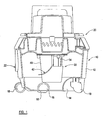
Figure 1 is a partly-section side elevation of a part of a cleaner in accordance with the invention. -
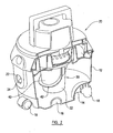
Figure 2 is a partly broken-away perspective view of the cleaner. -
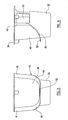
Figures 3 and 4 are respectively a front and side elevation of the float valve housing of the cleaner. -
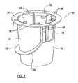
Figure 5 is a perspective view of the housing. - Referring firstly to
figures 1 and2 of the drawings, these illustrate a "wet" type of suction cleaner in accordance with the invention. The cleaner comprises atank 10 which is of circular shape in plan view, having aperipheral wall 12 which is slightly tapered from top to bottom with a lower wall which is of a complex shape, having a number of peripheral upwardly and radially-inwardly extending recesses, two of which are indicated at 14, 16 in which are disposedrespective castors 18 enabling the cleaner to be moved over a floor surface. The top of thetank 10 is closed by a body indicated generally at 20. - The
body 20 extends upwardly from the top of thetank 10, and has fitted within it an electric motor and fan assembly by which air can be drawn from the interior of thetank 10 and cause air to be drawn into the tank through aninlet aperture 22 in theperipheral wall 12 of the tank. Theinlet 22 has a fitting 24 for bayonet-type connection of a suction hose, not shown. Such provision of an inlet in the peripheral wall of a tank of a wet-type suction cleaner, and the disposition of an electric motor and fan in an upper body part of the cleaner, are well known and hence will not be described in any greater detail herein. Facing the interior of thetank 10, thebody 20 has an outlet port which leads to the fan, and from the fan an exhaust passage for air sucked through the tank by the fan leads to the external atmosphere. - A float valve assembly indicated generally at 30 extends downwardly within the
tank 10 from the centre of thebody 20. The float valve assembly comprises a housing whose configuration is shown in greater detail infigures 3 to 5 of the drawings. The housing indicated generally at 32 is of downwardly-tapering part-conical configuration, with alateral flange 34 at its uppermost end. Theflange 34 has three circumferentially spaced apertures one of which is indicated at 36, for receiving fasteners such as bolts or screws by which the housing can be secured to the lower surface of thebody 20 around the outlet port therein. The housing is provided with six circumferentially spaced radially inwardly extending guide ribs as indicated at 38, which guide a float member (not shown) for movement upwardly and downwardly within thehousing 32. The float member may be spherical, or possibly of cylindrical or some other form, and is arranged to contact and occlude the outlet port when the level of liquid in the tank has reached an acceptable maximum, thereby preventing any further suction of air from the interior of the tank by the fan of the cleaner and thus any further sucking up of liquid. Such provision in wet type suction cleaners is well known. - The
housing 32 has, on one side thereof in its upper region, animpingement surface 40 which faces theinlet 22 to the tank. The impingement surface is bounded by adeflector formation 42 in the form of a wall which extends radially outwardly from the exterior surface of thehousing 32.Opposite ends 44, 46 of thedeflector formation 42 extend downwardly from theperipheral flange 34 at the top of thehousing 32, and then the respective parts of the deflector formation are curved at 48, 50 until they extend circumferentially of the housing and meet one another, at 52. Thus the deflector formation as a whole is generally C- or U-shaped. - At the opposite side of the
housing 32 from theimpingement surface 40, the housing is provided with an opening 54 leading into the interior of the housing, the opening being divided into three parts by two of theribs 38. These provide for access of air to the interior of thehousing 32 whence it is drawn through the outlet port to the fan and is then expelled to the external atmosphere, provided the level of liquid within thetank 10 is not sufficient to cause the float member to rise sufficiently far within thehousing 32 to block the outlet port. - The
impingement surface 40 of the housing faces the inlet opening 22. If liquid is entrained in the suction air flow entering the tank through theinlet 22, it impinges on thesurface 40 which causes drops of the liquid to be separated from the air flow. Such separated liquid runs under gravity down thesurface 40, being guided by thedeflector formation 42 to thelower part 52 of the formation to fall into the tank. Theparts 44, 46 of the deflector formation keep such liquid from being drawn by the suction air flow through theopening 54 to reach the outlet port and fan. - It will be appreciated that modifications may be made, relative to the illustrated embodiment of the invention, while remaining within the broad scope of the invention. For example, the tank of the cleaner may be of other than a circular shape in plan view, as may the float valve assembly, and the latter need not be at the centre of the tank but instead may be nearer one wall post of the tank than another.
- When used in this specification and claims, the terms "comprises" and "comprising" and variations thereof mean that the specified features, steps or integers are included. The terms are not to be interpreted to exclude the presence of other features, steps or components.
Claims (10)
- A float valve assembly (30) for fitting in a wet-type suction cleaner, comprising
a housing (32) having, or adapted for co-operation with, an outlet port,
a float member movable relative to the housing to cause closure of the outlet port, an impingement surface (40) on the housing exterior and facing in a first direction, an opening (54) in the housing exterior, leading to the outlet port, the opening (54) facing in a direction away from that faced by the impingement surface, and a deflecting means (42) for deflecting matter from the impingement surface away from the opening in the housing, and characterised in that the deflecting means (42) comprises a wall formation (44, 46, 48, 50) extending outwardly from the housing exterior and disposed between the opening (54) and the impingement surface (40), the deflecting means having opposite end portions (44, 46) extending downwardly from an upper end of the housing at opposite sides thereof, opposite parts (48, 50) of the deflecting means converging to meet one another at a lower part of the housing opposite the opening. - A float valve assembly according to claim 1 wherein the impingement surface (40) comprises about half the peripheral extent of the housing (32).
- A float valve assembly according to claim 2 wherein the opening (54) comprises about the opposite half of the peripheral extent of the housing (32).
- A float valve assembly according to any one of the preceding claims, wherein the housing (32) is generally circular in cross section.
- A float valve assembly according to any one of the preceding claims, wherein the float member is guided for movement upwardly and downwardly within the housing.
- A float valve assembly according to claim 5 wherein the float member is guided by inwardly extending ribs (38) oriented upwardly and downwardly of the housing interior.
- A wet type suction cleaner comprising a tank (10) having an inlet (22) for suction-induced air flow, a fan for creating the suction and a float valve assembly (30) as claimed in any one of claims 1-6, wherein the inlet (22) directs the suction-induced air flow against the impingement surface (40).
- A suction cleaner according to claim 7 wherein the float valve assembly (30) extends downwardly into the tank (10), at or close to the centre thereof in plan view, from a body (20) fitting on top of the tank.
- A suction cleaner according to claim 8 wherein the tank (10) is substantially circular in plan view.
- A suction cleaner according to claim 9 wherein the inlet (22) to the tank (10) is provided in a peripheral wall thereof, spaced above the bottom of the tank and extending substantially radially to face the impingement surface (40) of the float valve assembly (30).
Applications Claiming Priority (2)
| Application Number | Priority Date | Filing Date | Title |
|---|---|---|---|
| GB0610850A GB2438583A (en) | 2006-06-02 | 2006-06-02 | Wet suction cleaner deflector |
| PCT/GB2007/002003 WO2007141485A1 (en) | 2006-06-02 | 2007-05-31 | Wet type suction cleaners |
Publications (2)
| Publication Number | Publication Date |
|---|---|
| EP2023787A1 EP2023787A1 (en) | 2009-02-18 |
| EP2023787B1 true EP2023787B1 (en) | 2012-08-29 |
Family
ID=36694780
Family Applications (1)
| Application Number | Title | Priority Date | Filing Date |
|---|---|---|---|
| EP07733019A Not-in-force EP2023787B1 (en) | 2006-06-02 | 2007-05-31 | Wet type suction cleaners |
Country Status (8)
| Country | Link |
|---|---|
| US (1) | US8099829B2 (en) |
| EP (1) | EP2023787B1 (en) |
| CN (1) | CN101478908B (en) |
| AU (1) | AU2007255247B2 (en) |
| ES (1) | ES2394011T3 (en) |
| GB (1) | GB2438583A (en) |
| RU (1) | RU2416355C2 (en) |
| WO (1) | WO2007141485A1 (en) |
Families Citing this family (5)
| Publication number | Priority date | Publication date | Assignee | Title |
|---|---|---|---|---|
| GB2438583A (en) | 2006-06-02 | 2007-12-05 | Vax Ltd | Wet suction cleaner deflector |
| KR20110021553A (en) * | 2009-08-26 | 2011-03-04 | 삼성광주전자 주식회사 | Wet Dust Collector of Vacuum Cleaner |
| USD841418S1 (en) | 2017-09-29 | 2019-02-26 | Mitchell Kidd | Flange wrench |
| WO2021141778A1 (en) | 2020-01-06 | 2021-07-15 | Techtronic Cordless Gp | Cleaning system with full recovery tank shutoff |
| AU2023425744A1 (en) | 2023-01-20 | 2025-07-31 | Sharkninja Operating Llc | Extraction cleaner |
Family Cites Families (12)
| Publication number | Priority date | Publication date | Assignee | Title |
|---|---|---|---|---|
| US4142270A (en) * | 1977-03-04 | 1979-03-06 | Nauta Jelle G | Wet-dry vacuum cleaner baffle strainer system |
| DE3243506C2 (en) * | 1981-07-16 | 1985-09-26 | Guido Oberdorfer Wap-Maschinen, 7919 Bellenberg | Dirt vacuum cleaner with filter cartridge |
| AU5120693A (en) * | 1992-10-13 | 1994-05-09 | Kipley Roydon Marks | Separator |
| US5259854A (en) * | 1992-12-23 | 1993-11-09 | Gpac, Inc. | Disposable HEPA filtration device |
| DE9405605U1 (en) * | 1994-04-02 | 1994-06-16 | Erma Reinigungstechnik Gmbh, 71229 Leonberg | Vacuum and water vacuum |
| US5954863A (en) * | 1996-11-18 | 1999-09-21 | Loveless; Michael L. | Wet and dry vacuum with float valve system |
| US6101669A (en) * | 1998-06-04 | 2000-08-15 | Emerson Electric Co. | Wet/dry vacuum |
| US6113663A (en) * | 1998-11-10 | 2000-09-05 | Shop Vac Corporation | Vacuum cleaner having a dual filter assembly |
| GB2360200A (en) * | 2000-03-13 | 2001-09-19 | Wah Hang Alfred Yuen | Attachment for adapting a dry-suction vacuum cleaner for wet use |
| GB2405577A (en) * | 2003-09-05 | 2005-03-09 | Reckitt Benckiser | Cleaning Device |
| RU2269919C2 (en) * | 2004-04-02 | 2006-02-20 | Борис Аркадьевич Криман | Liquid vacuum cleaner with one or more suction branch pipes |
| GB2438583A (en) | 2006-06-02 | 2007-12-05 | Vax Ltd | Wet suction cleaner deflector |
-
2006
- 2006-06-02 GB GB0610850A patent/GB2438583A/en not_active Withdrawn
-
2007
- 2007-05-31 ES ES07733019T patent/ES2394011T3/en active Active
- 2007-05-31 CN CN2007800235039A patent/CN101478908B/en not_active Expired - Fee Related
- 2007-05-31 EP EP07733019A patent/EP2023787B1/en not_active Not-in-force
- 2007-05-31 US US12/303,198 patent/US8099829B2/en not_active Expired - Fee Related
- 2007-05-31 AU AU2007255247A patent/AU2007255247B2/en not_active Ceased
- 2007-05-31 WO PCT/GB2007/002003 patent/WO2007141485A1/en not_active Ceased
- 2007-05-31 RU RU2008152320/12A patent/RU2416355C2/en not_active IP Right Cessation
Also Published As
| Publication number | Publication date |
|---|---|
| AU2007255247B2 (en) | 2011-12-15 |
| RU2416355C2 (en) | 2011-04-20 |
| US20100132152A1 (en) | 2010-06-03 |
| EP2023787A1 (en) | 2009-02-18 |
| ES2394011T3 (en) | 2013-01-04 |
| GB2438583A (en) | 2007-12-05 |
| GB0610850D0 (en) | 2006-07-12 |
| CN101478908A (en) | 2009-07-08 |
| US8099829B2 (en) | 2012-01-24 |
| RU2008152320A (en) | 2010-07-20 |
| WO2007141485A1 (en) | 2007-12-13 |
| AU2007255247A1 (en) | 2007-12-13 |
| CN101478908B (en) | 2012-02-15 |
Similar Documents
| Publication | Publication Date | Title |
|---|---|---|
| US8707510B2 (en) | Extraction cleaner and centrifugal air/water separator therefor | |
| KR100612204B1 (en) | Multi cyclone dust collector and vacuum cleaner having same | |
| US9675220B2 (en) | Wet/dry, non-porous bag/bagless vacuum assembly with steam and variable speed settable vacuum motor control with no loss of suction | |
| KR100607441B1 (en) | Grill member, cyclone dust collector and vacuum cleaner having same | |
| CN101449948B (en) | Cyclone system for dust collector and dust collector with the same | |
| US20030132152A1 (en) | Vortex pool cleaner | |
| WO2017101255A1 (en) | Filtering-liquid container for de-dusting equipment and de-dusting equipment having same | |
| US8099829B2 (en) | Wet type suction cleaners | |
| JP2007111397A (en) | Wet vacuum cleaner | |
| CN102149310B (en) | Vacuum cleaner | |
| KR20220139900A (en) | wet vacuum cleaner | |
| US8920549B2 (en) | Wet-type dust collector for a vacuum cleaner | |
| CN104367266A (en) | Handheld dust collector | |
| EP3122223B1 (en) | A separator assembly for a suction cleaning apparatus | |
| KR100206390B1 (en) | Suction kit for vacuum cleaners | |
| KR101049106B1 (en) | Exhaust structure of vacuum cleaner combined with water cleaning | |
| CN1437910A (en) | Cyclone type duster | |
| KR101065676B1 (en) | Water vacuum cleaner | |
| EP4090208B1 (en) | Cyclone unit for a wet vacuum cleaner | |
| CN211796202U (en) | Cyclonic suction head device | |
| CN102599851A (en) | Motor box structure for lowering noise of motor | |
| GB2184000A (en) | Suction apparatus | |
| CN121419702A (en) | Dust collection device and vacuum cleaner equipped with dust collection device | |
| JP2009201884A (en) | Vacuum cleaner | |
| SE505323C2 (en) | Vacuum equipment with fluid and particle sepg. filter |
Legal Events
| Date | Code | Title | Description |
|---|---|---|---|
| PUAI | Public reference made under article 153(3) epc to a published international application that has entered the european phase |
Free format text: ORIGINAL CODE: 0009012 |
|
| 17P | Request for examination filed |
Effective date: 20081215 |
|
| AK | Designated contracting states |
Kind code of ref document: A1 Designated state(s): AT BE BG CH CY CZ DE DK EE ES FI FR GB GR HU IE IS IT LI LT LU LV MC MT NL PL PT RO SE SI SK TR |
|
| AX | Request for extension of the european patent |
Extension state: AL BA HR MK RS |
|
| 17Q | First examination report despatched |
Effective date: 20100610 |
|
| GRAP | Despatch of communication of intention to grant a patent |
Free format text: ORIGINAL CODE: EPIDOSNIGR1 |
|
| GRAS | Grant fee paid |
Free format text: ORIGINAL CODE: EPIDOSNIGR3 |
|
| GRAA | (expected) grant |
Free format text: ORIGINAL CODE: 0009210 |
|
| DAX | Request for extension of the european patent (deleted) | ||
| AK | Designated contracting states |
Kind code of ref document: B1 Designated state(s): AT BE BG CH CY CZ DE DK EE ES FI FR GB GR HU IE IS IT LI LT LU LV MC MT NL PL PT RO SE SI SK TR |
|
| REG | Reference to a national code |
Ref country code: GB Ref legal event code: FG4D |
|
| REG | Reference to a national code |
Ref country code: CH Ref legal event code: EP |
|
| REG | Reference to a national code |
Ref country code: AT Ref legal event code: REF Ref document number: 572584 Country of ref document: AT Kind code of ref document: T Effective date: 20120915 |
|
| REG | Reference to a national code |
Ref country code: IE Ref legal event code: FG4D |
|
| REG | Reference to a national code |
Ref country code: DE Ref legal event code: R096 Ref document number: 602007025117 Country of ref document: DE Effective date: 20121025 |
|
| REG | Reference to a national code |
Ref country code: ES Ref legal event code: FG2A Ref document number: 2394011 Country of ref document: ES Kind code of ref document: T3 Effective date: 20130104 |
|
| REG | Reference to a national code |
Ref country code: AT Ref legal event code: MK05 Ref document number: 572584 Country of ref document: AT Kind code of ref document: T Effective date: 20120829 |
|
| REG | Reference to a national code |
Ref country code: NL Ref legal event code: VDEP Effective date: 20120829 |
|
| REG | Reference to a national code |
Ref country code: LT Ref legal event code: MG4D Effective date: 20120829 |
|
| PG25 | Lapsed in a contracting state [announced via postgrant information from national office to epo] |
Ref country code: CY Free format text: LAPSE BECAUSE OF FAILURE TO SUBMIT A TRANSLATION OF THE DESCRIPTION OR TO PAY THE FEE WITHIN THE PRESCRIBED TIME-LIMIT Effective date: 20120829 Ref country code: IS Free format text: LAPSE BECAUSE OF FAILURE TO SUBMIT A TRANSLATION OF THE DESCRIPTION OR TO PAY THE FEE WITHIN THE PRESCRIBED TIME-LIMIT Effective date: 20121229 Ref country code: LT Free format text: LAPSE BECAUSE OF FAILURE TO SUBMIT A TRANSLATION OF THE DESCRIPTION OR TO PAY THE FEE WITHIN THE PRESCRIBED TIME-LIMIT Effective date: 20120829 Ref country code: AT Free format text: LAPSE BECAUSE OF FAILURE TO SUBMIT A TRANSLATION OF THE DESCRIPTION OR TO PAY THE FEE WITHIN THE PRESCRIBED TIME-LIMIT Effective date: 20120829 Ref country code: FI Free format text: LAPSE BECAUSE OF FAILURE TO SUBMIT A TRANSLATION OF THE DESCRIPTION OR TO PAY THE FEE WITHIN THE PRESCRIBED TIME-LIMIT Effective date: 20120829 |
|
| PG25 | Lapsed in a contracting state [announced via postgrant information from national office to epo] |
Ref country code: LV Free format text: LAPSE BECAUSE OF FAILURE TO SUBMIT A TRANSLATION OF THE DESCRIPTION OR TO PAY THE FEE WITHIN THE PRESCRIBED TIME-LIMIT Effective date: 20120829 Ref country code: GR Free format text: LAPSE BECAUSE OF FAILURE TO SUBMIT A TRANSLATION OF THE DESCRIPTION OR TO PAY THE FEE WITHIN THE PRESCRIBED TIME-LIMIT Effective date: 20121130 Ref country code: BE Free format text: LAPSE BECAUSE OF FAILURE TO SUBMIT A TRANSLATION OF THE DESCRIPTION OR TO PAY THE FEE WITHIN THE PRESCRIBED TIME-LIMIT Effective date: 20120829 Ref country code: PT Free format text: LAPSE BECAUSE OF FAILURE TO SUBMIT A TRANSLATION OF THE DESCRIPTION OR TO PAY THE FEE WITHIN THE PRESCRIBED TIME-LIMIT Effective date: 20121231 Ref country code: SI Free format text: LAPSE BECAUSE OF FAILURE TO SUBMIT A TRANSLATION OF THE DESCRIPTION OR TO PAY THE FEE WITHIN THE PRESCRIBED TIME-LIMIT Effective date: 20120829 Ref country code: SE Free format text: LAPSE BECAUSE OF FAILURE TO SUBMIT A TRANSLATION OF THE DESCRIPTION OR TO PAY THE FEE WITHIN THE PRESCRIBED TIME-LIMIT Effective date: 20120829 |
|
| PG25 | Lapsed in a contracting state [announced via postgrant information from national office to epo] |
Ref country code: NL Free format text: LAPSE BECAUSE OF FAILURE TO SUBMIT A TRANSLATION OF THE DESCRIPTION OR TO PAY THE FEE WITHIN THE PRESCRIBED TIME-LIMIT Effective date: 20120829 Ref country code: EE Free format text: LAPSE BECAUSE OF FAILURE TO SUBMIT A TRANSLATION OF THE DESCRIPTION OR TO PAY THE FEE WITHIN THE PRESCRIBED TIME-LIMIT Effective date: 20120829 Ref country code: CZ Free format text: LAPSE BECAUSE OF FAILURE TO SUBMIT A TRANSLATION OF THE DESCRIPTION OR TO PAY THE FEE WITHIN THE PRESCRIBED TIME-LIMIT Effective date: 20120829 Ref country code: DK Free format text: LAPSE BECAUSE OF FAILURE TO SUBMIT A TRANSLATION OF THE DESCRIPTION OR TO PAY THE FEE WITHIN THE PRESCRIBED TIME-LIMIT Effective date: 20120829 Ref country code: RO Free format text: LAPSE BECAUSE OF FAILURE TO SUBMIT A TRANSLATION OF THE DESCRIPTION OR TO PAY THE FEE WITHIN THE PRESCRIBED TIME-LIMIT Effective date: 20120829 |
|
| PG25 | Lapsed in a contracting state [announced via postgrant information from national office to epo] |
Ref country code: PL Free format text: LAPSE BECAUSE OF FAILURE TO SUBMIT A TRANSLATION OF THE DESCRIPTION OR TO PAY THE FEE WITHIN THE PRESCRIBED TIME-LIMIT Effective date: 20120829 Ref country code: SK Free format text: LAPSE BECAUSE OF FAILURE TO SUBMIT A TRANSLATION OF THE DESCRIPTION OR TO PAY THE FEE WITHIN THE PRESCRIBED TIME-LIMIT Effective date: 20120829 |
|
| PLBE | No opposition filed within time limit |
Free format text: ORIGINAL CODE: 0009261 |
|
| STAA | Information on the status of an ep patent application or granted ep patent |
Free format text: STATUS: NO OPPOSITION FILED WITHIN TIME LIMIT |
|
| PG25 | Lapsed in a contracting state [announced via postgrant information from national office to epo] |
Ref country code: BG Free format text: LAPSE BECAUSE OF FAILURE TO SUBMIT A TRANSLATION OF THE DESCRIPTION OR TO PAY THE FEE WITHIN THE PRESCRIBED TIME-LIMIT Effective date: 20121129 |
|
| 26N | No opposition filed |
Effective date: 20130530 |
|
| REG | Reference to a national code |
Ref country code: DE Ref legal event code: R097 Ref document number: 602007025117 Country of ref document: DE Effective date: 20130530 |
|
| PG25 | Lapsed in a contracting state [announced via postgrant information from national office to epo] |
Ref country code: MC Free format text: LAPSE BECAUSE OF FAILURE TO SUBMIT A TRANSLATION OF THE DESCRIPTION OR TO PAY THE FEE WITHIN THE PRESCRIBED TIME-LIMIT Effective date: 20120829 |
|
| REG | Reference to a national code |
Ref country code: CH Ref legal event code: PL |
|
| PG25 | Lapsed in a contracting state [announced via postgrant information from national office to epo] |
Ref country code: CH Free format text: LAPSE BECAUSE OF NON-PAYMENT OF DUE FEES Effective date: 20130531 Ref country code: LI Free format text: LAPSE BECAUSE OF NON-PAYMENT OF DUE FEES Effective date: 20130531 |
|
| REG | Reference to a national code |
Ref country code: IE Ref legal event code: MM4A |
|
| PG25 | Lapsed in a contracting state [announced via postgrant information from national office to epo] |
Ref country code: IE Free format text: LAPSE BECAUSE OF NON-PAYMENT OF DUE FEES Effective date: 20130531 |
|
| PG25 | Lapsed in a contracting state [announced via postgrant information from national office to epo] |
Ref country code: MT Free format text: LAPSE BECAUSE OF FAILURE TO SUBMIT A TRANSLATION OF THE DESCRIPTION OR TO PAY THE FEE WITHIN THE PRESCRIBED TIME-LIMIT Effective date: 20120829 |
|
| PG25 | Lapsed in a contracting state [announced via postgrant information from national office to epo] |
Ref country code: TR Free format text: LAPSE BECAUSE OF FAILURE TO SUBMIT A TRANSLATION OF THE DESCRIPTION OR TO PAY THE FEE WITHIN THE PRESCRIBED TIME-LIMIT Effective date: 20120829 |
|
| PG25 | Lapsed in a contracting state [announced via postgrant information from national office to epo] |
Ref country code: LU Free format text: LAPSE BECAUSE OF NON-PAYMENT OF DUE FEES Effective date: 20130531 Ref country code: HU Free format text: LAPSE BECAUSE OF FAILURE TO SUBMIT A TRANSLATION OF THE DESCRIPTION OR TO PAY THE FEE WITHIN THE PRESCRIBED TIME-LIMIT; INVALID AB INITIO Effective date: 20070531 |
|
| PGFP | Annual fee paid to national office [announced via postgrant information from national office to epo] |
Ref country code: IT Payment date: 20150527 Year of fee payment: 9 |
|
| REG | Reference to a national code |
Ref country code: FR Ref legal event code: PLFP Year of fee payment: 10 |
|
| PG25 | Lapsed in a contracting state [announced via postgrant information from national office to epo] |
Ref country code: IT Free format text: LAPSE BECAUSE OF NON-PAYMENT OF DUE FEES Effective date: 20160531 |
|
| REG | Reference to a national code |
Ref country code: FR Ref legal event code: PLFP Year of fee payment: 11 |
|
| REG | Reference to a national code |
Ref country code: FR Ref legal event code: PLFP Year of fee payment: 12 |
|
| PGFP | Annual fee paid to national office [announced via postgrant information from national office to epo] |
Ref country code: ES Payment date: 20180601 Year of fee payment: 12 |
|
| REG | Reference to a national code |
Ref country code: ES Ref legal event code: FD2A Effective date: 20201001 |
|
| PG25 | Lapsed in a contracting state [announced via postgrant information from national office to epo] |
Ref country code: ES Free format text: LAPSE BECAUSE OF NON-PAYMENT OF DUE FEES Effective date: 20190601 |
|
| P01 | Opt-out of the competence of the unified patent court (upc) registered |
Effective date: 20230613 |
|
| PGFP | Annual fee paid to national office [announced via postgrant information from national office to epo] |
Ref country code: GB Payment date: 20240527 Year of fee payment: 18 |
|
| PGFP | Annual fee paid to national office [announced via postgrant information from national office to epo] |
Ref country code: DE Payment date: 20240530 Year of fee payment: 18 |
|
| PGFP | Annual fee paid to national office [announced via postgrant information from national office to epo] |
Ref country code: FR Payment date: 20240527 Year of fee payment: 18 |
|
| REG | Reference to a national code |
Ref country code: DE Ref legal event code: R119 Ref document number: 602007025117 Country of ref document: DE |
|
| GBPC | Gb: european patent ceased through non-payment of renewal fee |
Effective date: 20250531 |
|
| PG25 | Lapsed in a contracting state [announced via postgrant information from national office to epo] |
Ref country code: GB Free format text: LAPSE BECAUSE OF NON-PAYMENT OF DUE FEES Effective date: 20250531 |
|
| PG25 | Lapsed in a contracting state [announced via postgrant information from national office to epo] |
Ref country code: DE Free format text: LAPSE BECAUSE OF NON-PAYMENT OF DUE FEES Effective date: 20251202 |
|
| PG25 | Lapsed in a contracting state [announced via postgrant information from national office to epo] |
Ref country code: FR Free format text: LAPSE BECAUSE OF NON-PAYMENT OF DUE FEES Effective date: 20250531 |