EP2023481A2 - Elektrische Maschine - Google Patents
Elektrische Maschine Download PDFInfo
- Publication number
- EP2023481A2 EP2023481A2 EP08252410A EP08252410A EP2023481A2 EP 2023481 A2 EP2023481 A2 EP 2023481A2 EP 08252410 A EP08252410 A EP 08252410A EP 08252410 A EP08252410 A EP 08252410A EP 2023481 A2 EP2023481 A2 EP 2023481A2
- Authority
- EP
- European Patent Office
- Prior art keywords
- electrical
- period
- power
- inductive winding
- power source
- Prior art date
- Legal status (The legal status is an assumption and is not a legal conclusion. Google has not performed a legal analysis and makes no representation as to the accuracy of the status listed.)
- Granted
Links
Images

Classifications
-
- H—ELECTRICITY
- H02—GENERATION; CONVERSION OR DISTRIBUTION OF ELECTRIC POWER
- H02P—CONTROL OR REGULATION OF ELECTRIC MOTORS, ELECTRIC GENERATORS OR DYNAMO-ELECTRIC CONVERTERS; CONTROLLING TRANSFORMERS, REACTORS OR CHOKE COILS
- H02P25/00—Arrangements or methods for the control of AC motors characterised by the kind of AC motor or by structural details
- H02P25/02—Arrangements or methods for the control of AC motors characterised by the kind of AC motor or by structural details characterised by the kind of motor
- H02P25/08—Reluctance motors
-
- F—MECHANICAL ENGINEERING; LIGHTING; HEATING; WEAPONS; BLASTING
- F01—MACHINES OR ENGINES IN GENERAL; ENGINE PLANTS IN GENERAL; STEAM ENGINES
- F01D—NON-POSITIVE DISPLACEMENT MACHINES OR ENGINES, e.g. STEAM TURBINES
- F01D15/00—Adaptations of machines or engines for special use; Combinations of engines with devices driven thereby
- F01D15/10—Adaptations for driving, or combinations with, electric generators
-
- F—MECHANICAL ENGINEERING; LIGHTING; HEATING; WEAPONS; BLASTING
- F02—COMBUSTION ENGINES; HOT-GAS OR COMBUSTION-PRODUCT ENGINE PLANTS
- F02C—GAS-TURBINE PLANTS; AIR INTAKES FOR JET-PROPULSION PLANTS; CONTROLLING FUEL SUPPLY IN AIR-BREATHING JET-PROPULSION PLANTS
- F02C7/00—Features, components parts, details or accessories, not provided for in, or of interest apart form groups F02C1/00 - F02C6/00; Air intakes for jet-propulsion plants
- F02C7/26—Starting; Ignition
- F02C7/268—Starting drives for the rotor, acting directly on the rotor of the gas turbine to be started
- F02C7/275—Mechanical drives
-
- H—ELECTRICITY
- H02—GENERATION; CONVERSION OR DISTRIBUTION OF ELECTRIC POWER
- H02P—CONTROL OR REGULATION OF ELECTRIC MOTORS, ELECTRIC GENERATORS OR DYNAMO-ELECTRIC CONVERTERS; CONTROLLING TRANSFORMERS, REACTORS OR CHOKE COILS
- H02P6/00—Arrangements for controlling synchronous motors or other dynamo-electric motors using electronic commutation dependent on the rotor position; Electronic commutators therefor
- H02P6/14—Electronic commutators
- H02P6/16—Circuit arrangements for detecting position
- H02P6/18—Circuit arrangements for detecting position without separate position detecting elements
- H02P6/185—Circuit arrangements for detecting position without separate position detecting elements using inductance sensing, e.g. pulse excitation
-
- H—ELECTRICITY
- H02—GENERATION; CONVERSION OR DISTRIBUTION OF ELECTRIC POWER
- H02P—CONTROL OR REGULATION OF ELECTRIC MOTORS, ELECTRIC GENERATORS OR DYNAMO-ELECTRIC CONVERTERS; CONTROLLING TRANSFORMERS, REACTORS OR CHOKE COILS
- H02P2203/00—Indexing scheme relating to controlling arrangements characterised by the means for detecting the position of the rotor
- H02P2203/01—Motor rotor position determination based on the detected or calculated phase inductance, e.g. for a Switched Reluctance Motor
Definitions
- the present invention relates to electrical machines and more particularly to electrical machines such as switched reluctance electrical machines in which electrical current is injected in order to provide a motoring function or a generating function.
- Electrical machines are utilised in a wide range of environments and for a large number of purposes. Of particular interest with regard to aspects of the present invention is utilisation of electrical machines within gas turbine engines. These electrical machines are utilised for provision of electrical generating capacity as well as in order to act as electrical motors for various functions. There is a desire to locate such electrical machines as closely as possibly and preferably embedded within the gas turbine engine. By such an approach complex mechanical transmission mechanisms are removed giving significant operational and efficiency benefits.
- Such electrical machines can act as generators as well as starter motors for the gas turbine engine.
- the electrical machine in normal operation as indicated would generally act as an electrical generator but during such starting functions it will be understood that the electrical machine will temporarily act as a motor.
- Generation systems typically utilise power electronic converters to enable very high power density electrical machine technologies to be used. Such technologies include switched reluctance electrical machines. High densities enable further size and weight benefits to be achieved in comparison with traditional synchronous electrical machines. Additionally, the inherent direct electrical current interface allows parallel connection and sharing of electrical power generated by different spools of the gas turbine engine.
- an electrical machine arrangement comprising inductive winding elements cyclically energisable for an electrical motor function by a power pulse given by a power source to generate continuous torque in a rotor, each power pulse provided during a motor period in a rotational cycle and separated by spacer periods to facilitate rotation of the rotor, the inductive winding elements coupled to an electrical power injector to inject electrical power for storage in the inductance element during the spacer periods to augment the power pulse provided by the power source.
- a method of operating an electrical machine comprises cyclically energising an inductive winding elements to generate continuous torque in a rotor by applying a power pulse from the power source during motor periods in a rotational cycle and additionally injecting electrical energy to the inductive winding elements during spacer periods of the rotational cycle for storage in the inductance element and determining the value of the injected electrical energy to adjust the necessary capacity of the power source.
- each inductive winding element is an electrical coil or winding.
- the electrical machine is a switched reluctance electrical machine capable of providing a generating and/or motoring function.
- the power source is a capacitor.
- the capacitor is a film foil capacitor.
- the power pulse is followed by a generator period. Possibly, electrical energy is injected into the inductive winding elements during its generator period.
- each inductive winding element shares electrical power at least in the spacer period with other inductive winding elements.
- the injected electrical power provides a negative torque to the continuous torque upon the rotor.
- the negative torque is within a 10% reduction range of the continuous torque as presented to the rotor.
- the motor (or generator) period and the spacer period are defined by rotational angles of the rotational cycle subtended by the rotor.
- the electrical power injector is associated with a monitor for the power source to determine voltage disturbances in the power source and dependent upon any voltage disturbance adjust the value and/or period of injection of electrical pulse to the inductive winding element in the spacer period. Possibly, the monitor also determines whether an electrical pulse or part of an electrical pulse is injected in the generator (or motor) period.
- Electrical machines as described above are used in a wide variety of situations. Of particular interest with regards to aspects of the present invention are switched reluctance electrical machines in which power pulses are provided to inductive winding elements in order to generate rotation.
- the electrical inductive winding elements are typically stator windings which are cyclically and sequentially energised in order to provide and stimulate rotation in the rotor.
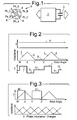
- FIG. 1 provides a schematic illustration of an electrical machine arrangement in accordance with aspects of the present invention.
- a switched reluctance electrical machine 1 comprises a number of inductance element pairs Ph-A, Ph-B and Ph-C. These inductance elements Ph as indicated are energised by injecting electrical power pulses in the form of electrical current presented from a power source 2.
- the electrical machine 1 illustrated in Figure 1 is three phase in that there are three pairs of inductance elements Ph energised by electrical current injection from the power source 2.
- the power source 2 is associated with a capacitor 3 which acts to ensure that rapid switching of the power pulses to the inductance elements Ph can be achieved.
- the electrical machine arrangement in the embodiment depicted in accordance with aspects of the present invention there is a switched reluctance electrical machine which can operate as an electrical power generator or an electrical motor.
- the electrical machine can initiate start up of that gas turbine engine and then once that function has been achieved can operate subsequently as an electrical power generator.
- Figure 2 shows the idealised inductance variation in the inductance elements Ph over rotational angle for a rotational cycle between W and Z with a constant electrical current excitation of an inductance element. It is known that electrical inductance observed by stator windings as electrical inductance elements Ph changes as the rotor sequences through its rotational cycle W to Z. Such variations in the electrical inductance are due to rotor poles 4 of the machine 1 moving into and out of alignment with the inductance elements Ph. As indicated Figure 2 shows idealised inductance changes ignoring saturation effects along with corresponding torque variations for a fixed injected electrical current to the stator windings or inductance elements Ph by the source 2.
- Injection of electrical current as a power pulse during a rising inductance or motor period 5 causes the machine 1 to act as an electrical motor whereas injection of electrical current during a falling inductance or generator period 6 causes the machine 1 to behave as an electrical power generator.
- FIG. 2 is an idealised representation but provides a basic understanding of an electrical machine 1. It will be understood that the injected electrical current 11 in a practical electrical machine will not be as constant as illustrated in Figure 2 but rather pulsed in the respective motor period 5 or generator period 6 as required by particular electrical machine performance criteria.
- aspects of the present invention utilise the spacer period 9 to effectively store electrical energy. It will be appreciated that during the spacer period 9 any electrical power injected as electrical current can lead to no torque production due to the misalignment of the poles 4 and inductance elements Ph. Thus during this spacer period 9 it will be understood that the machine 1 can store electrical energy in accordance with the relationship, stored electrical energy equals 1 ⁇ 2 LI 2 where L is the inductance and I is the electrical current.
- the electrical machine as a switched reluctance machine is limited to either motoring or generating by carefully controlling the rotational angles at which electrical current as power pulses is injected into the inductance elements as stator windings, that is to say over rotational angles W to X or X to Y.
- electrical energy can be stored at least during the spacer period 9 which results in a reduced duty load to the capacitor 3.
- the electrical energy storage functionality normally provided solely in prior electrical machines by the capacitor 3 is augmented in the present machine by the electrical inductance element Ph having energy stored and released over the spacer period 9 defined by appropriate rotational angles Y to Z during each rotor rotational cycle.
- each phase of the electrical machine is allowed to store and release energy appropriately in order to augment the capacitor 3 in terms of the power pulse provided to the machine 1.
- Such an approach will allow a reduction in the size as well as weight of the capacitor component necessary to achieve operational performance. It will be appreciated that injection of electrical power in the form of electrical current in the spacer period effectively enables provision of a controlled active filter for the electrical machine.
- FIG. 3 illustrates electrical current injection as a power pulse for torque generation and electrical current injection as inject electrical power for storage in accordance with aspects of the present invention in relation to changes in inductance for a three phase, that is to say three inductive winding elements, electrical machine.
- each phase successfully takes over an additional active filtering operation in accordance with aspects of the present invention.
- the active filtering operation is continuously available, that is to say electrical energy is stored in the inductive winding element to offset and augment the power source (electrical capacitor 3) in terms of the electrical capacitance capability required for operational performance.
- the inductive winding elements of the electrical machine effectively share electrical energy in order to distribute that electrical energy for storage in the spacer period 9.
- FIG. 3 shows for an example motoring configuration for the electrical machine electrical current injection 20 occurs during a motoring period 5 (rotational angle W to X) such that electrical current injection as electrical power in the period 21 can be provided without a negative effect upon the nett torque provided by the electrical machine.
- Figure 4 illustrates variations in inductance within an inductive winding element as electrical current or energy is injected into an inductance element.
- an electrical current 30 is injected during the motoring period 5 and as with regard to Figure 3 electrical energy in the form of injected electrical current 31 injected during a spacer period is stored in the inductance element but in addition further electrical energy in the form of an injected current 32 is provided during a generator period 6.
- the injected electrical current 32 as electrical power for storage is generally of a much lower value in order to limit the negative torque generation in comparison with the progressive torque provided by the motoring injected electrical current 30.
- FIG. 5 schematically illustrates circuitry to provide operation of the electrical machine in a main phase, that is to say to provide nett motoring torque to an electrical machine in comparison with a dead phase electrical energy injection to the inductance element for storage during a spacer period and for comparison with injection during an opposing phase that is to say generating period 6 ( Figure 2 ).
- a power source 40 including a capacitance 41 causes electrical current 42 to flow in the direction of the arrowheads for inductance element 43 in the form of a winding or coil.
- a motoring function is achieved.
- the electrical current 42 is only applied for a period defined by a rotational angle for a rotor within the electrical machine in order to generate the nett torque as indicated. Control of such current 42 flow is achieved through switches SW1 and SW2.
- a monitor 52 is provided to compare voltage demand (V demand) to measured voltage (V meas).
- V demand voltage demand
- V meas measured voltage
- the controller 51 will either absorb or discharge energy from the inductance element 43.
- Such absorption or discharge of electrical energy for storage in the inductance element 43 may result in an electrical current 52, 53 flowing into or out of the inductance element 43 dependant upon determination by the monitor 52 of voltage disturbances in the capacitor 41 of the power source 40.
- Such injection will be through an electrical power controller device 51 but typically associated with the monitor 52.
- circuit 55b The value of injected electrical power in the dead phase (shown as circuit 55b) or opposing phase (shown as circuit 55c) will depend on the disturbance in the voltage as indicated and determined by the monitor. Generally a desired level of energy storage within the inductance element 43 will be achieved. Particularly with regard to the opposed phase flow 53 as indicated such injection of electrical current as electrical energy will oppose the main function of the electrical machine and therefore consideration must be made as to that detrimental effect in comparison with the benefits of reduction in capacitor 41 size.
- the inductance element 43 can be operated in a generator mode consistent with generator period 6 as depicted in Figure 2 .
- electrical current will be injected into the electrical machine in the generator period 6 in order that the electrical machine acts as an electrical generator in accordance with aspects of the present invention.
- electrical energy can be stored in the spacer period 9 with limited if any detrimental effect upon generating function whilst electrical energy injected during the motor period 5 will have a detrimental effect upon electrical power generation.
- aspects of the present invention have particular applicability with regard to electrical machines where size, weight and cost of installation of equipment are concerns and must be minimised. Such applications include with regard to aerospace, mining, industrial and energy businesses.
Landscapes
- Engineering & Computer Science (AREA)
- Mechanical Engineering (AREA)
- General Engineering & Computer Science (AREA)
- Power Engineering (AREA)
- Chemical & Material Sciences (AREA)
- Combustion & Propulsion (AREA)
- Synchronous Machinery (AREA)
- Control Of Electric Motors In General (AREA)
Applications Claiming Priority (1)
| Application Number | Priority Date | Filing Date | Title |
|---|---|---|---|
| GBGB0715472.7A GB0715472D0 (en) | 2007-08-09 | 2007-08-09 | An electrical machine |
Publications (3)
| Publication Number | Publication Date |
|---|---|
| EP2023481A2 true EP2023481A2 (de) | 2009-02-11 |
| EP2023481A3 EP2023481A3 (de) | 2014-02-26 |
| EP2023481B1 EP2023481B1 (de) | 2017-03-01 |
Family
ID=38543259
Family Applications (1)
| Application Number | Title | Priority Date | Filing Date |
|---|---|---|---|
| EP08252410.9A Ceased EP2023481B1 (de) | 2007-08-09 | 2008-07-15 | Elektrische Maschine |
Country Status (3)
| Country | Link |
|---|---|
| US (1) | US7830105B2 (de) |
| EP (1) | EP2023481B1 (de) |
| GB (1) | GB0715472D0 (de) |
Families Citing this family (3)
| Publication number | Priority date | Publication date | Assignee | Title |
|---|---|---|---|---|
| US7710081B2 (en) * | 2006-10-27 | 2010-05-04 | Direct Drive Systems, Inc. | Electromechanical energy conversion systems |
| GB0804866D0 (en) * | 2008-03-17 | 2008-04-16 | Rolls Royce Plc | Electrical machine arrangement |
| US10224848B2 (en) * | 2017-01-30 | 2019-03-05 | Pratt & Whitney Canada Corp. | Method and system for synchronizing generators |
Family Cites Families (13)
| Publication number | Priority date | Publication date | Assignee | Title |
|---|---|---|---|---|
| US5010267A (en) * | 1988-09-09 | 1991-04-23 | Wisconsin Alumni Research Foundation | Variable speed machine with high power density |
| GB9401023D0 (en) | 1994-01-20 | 1994-03-16 | Univ Leicester | Electric motor |
| US5703456A (en) * | 1995-05-26 | 1997-12-30 | Emerson Electric Co. | Power converter and control system for a motor using an inductive load and method of doing the same |
| US5929590A (en) * | 1997-01-07 | 1999-07-27 | Emerson Electric Co. | Method and apparatus for implementing sensorless control of a switched reluctance machine |
| US6766874B2 (en) * | 1998-09-29 | 2004-07-27 | Hitachi, Ltd. | System for driving hybrid vehicle, method thereof and electric power supply system therefor |
| GB0028733D0 (en) * | 2000-11-24 | 2001-01-10 | Switched Reluctance Drives Ltd | Current chopping in switched reluctance drive systems |
| DE10134454A1 (de) * | 2001-07-16 | 2003-02-13 | Hilti Ag | Steuerverfahren und Schaltung zum Abbremsen eines elektronisch kommutierten Elektromotors |
| EP1678818A1 (de) * | 2003-09-30 | 2006-07-12 | Emerson Electric Co. | Positions-detektion für eine maschine mit geschalteter reluktanz |
| DE502004012073D1 (de) * | 2003-11-06 | 2011-02-10 | Continental Teves Ag & Co Ohg | Verfahren zur ermittlung der rotorlage einer synchronmaschine |
| KR100757060B1 (ko) * | 2005-04-01 | 2007-09-10 | 엘지전자 주식회사 | 저속에서의 발전 효율이 개선된 에스알 발전기 |
| KR100704482B1 (ko) * | 2005-04-01 | 2007-04-09 | 엘지전자 주식회사 | 저속 영역과 고속 영역에서의 발전 효율이 개선된 에스알발전기 |
| JP2009219345A (ja) * | 2008-02-15 | 2009-09-24 | Seiko Epson Corp | 発電装置及び電動装置 |
| GB0804866D0 (en) * | 2008-03-17 | 2008-04-16 | Rolls Royce Plc | Electrical machine arrangement |
-
2007
- 2007-08-09 GB GBGB0715472.7A patent/GB0715472D0/en not_active Ceased
-
2008
- 2008-07-15 EP EP08252410.9A patent/EP2023481B1/de not_active Ceased
- 2008-07-21 US US12/176,663 patent/US7830105B2/en not_active Expired - Fee Related
Also Published As
| Publication number | Publication date |
|---|---|
| EP2023481B1 (de) | 2017-03-01 |
| US7830105B2 (en) | 2010-11-09 |
| GB0715472D0 (en) | 2007-09-19 |
| US20090039652A1 (en) | 2009-02-12 |
| EP2023481A3 (de) | 2014-02-26 |
Similar Documents
| Publication | Publication Date | Title |
|---|---|---|
| US11391258B2 (en) | Engine starting system using stored energy | |
| US7514806B2 (en) | Engine start system with quadrature AC excitation | |
| KR101087948B1 (ko) | 가변 릴럭턴스 장치 및 가변 릴럭턴스 장치의 발전기동작방법 | |
| US20030020436A1 (en) | Switched reluctance generator and a method of controlling such a generator | |
| US7116073B1 (en) | Methods and apparatus for controlling a motor/generator | |
| EP2023481B1 (de) | Elektrische Maschine | |
| Chen | Implementation of a three-phase switched reluctance generator system for wind power applications | |
| KR20080086360A (ko) | 교류기용 파워 전자 회로 장치 | |
| US8193750B2 (en) | Electrical machine arrangement | |
| KR20020090335A (ko) | 기계 및 부하 특성의 동기화 방법 및 시스템 | |
| Nedic et al. | Experimental verification of induced voltage self-excitation of a switched reluctance generator | |
| US7135829B1 (en) | Methods and apparatus for controlling a motor/generator | |
| Wen et al. | Fault-tolerant control of excitation fault in doubly salient electromagnetic generator | |
| JP5863817B2 (ja) | 非同期機を含む航空機の電源回路 | |
| Reshetnikov | Permanent magnet machine control of starter-generator | |
| Srivastava et al. | Pm Enhanced Sensing Of Internal Emf Variation-A Tool To Study PMBLDC/AC Motors | |
| EP1753123A2 (de) | Verfahren und Vorrichtung zur Regelung eines Motorgenerators | |
| Ochjie et al. | Design/performance of a flux switching generator system for variable speed applications | |
| RU115134U1 (ru) | Система стабилизации напряжения переменного тока | |
| Zhou et al. | A Novel Initial Rotor Position Estimation Strategy for Doubly Salient Electromagnetic Machine with Two Test Pulses Injetcion | |
| Bherde et al. | Ultra low frequency low power oscillator using ultra-capacitor and advanced flywheel | |
| Chandrasekaran et al. | Performance, analysis of a new converter for switched reluctance motor drive with component sharing | |
| Shao et al. | Optimal Output Power Control of Switched Reluctance Generator at a Constant Speed | |
| Huang et al. | DC-link Voltage Control Method for High Speed Motors powered by Z-source Inverter | |
| RU2465713C2 (ru) | Способ перевозбуждения синхронного гистерезисного двигателя реакцией якоря |
Legal Events
| Date | Code | Title | Description |
|---|---|---|---|
| PUAI | Public reference made under article 153(3) epc to a published international application that has entered the european phase |
Free format text: ORIGINAL CODE: 0009012 |
|
| AK | Designated contracting states |
Kind code of ref document: A2 Designated state(s): AT BE BG CH CY CZ DE DK EE ES FI FR GB GR HR HU IE IS IT LI LT LU LV MC MT NL NO PL PT RO SE SI SK TR |
|
| AX | Request for extension of the european patent |
Extension state: AL BA MK RS |
|
| PUAL | Search report despatched |
Free format text: ORIGINAL CODE: 0009013 |
|
| AK | Designated contracting states |
Kind code of ref document: A3 Designated state(s): AT BE BG CH CY CZ DE DK EE ES FI FR GB GR HR HU IE IS IT LI LT LU LV MC MT NL NO PL PT RO SE SI SK TR |
|
| AX | Request for extension of the european patent |
Extension state: AL BA MK RS |
|
| RIC1 | Information provided on ipc code assigned before grant |
Ipc: H02P 25/08 20060101AFI20140117BHEP |
|
| 17P | Request for examination filed |
Effective date: 20140826 |
|
| AKX | Designation fees paid |
Designated state(s): DE FR GB IT |
|
| RAP1 | Party data changed (applicant data changed or rights of an application transferred) |
Owner name: ROLLS-ROYCE PLC |
|
| GRAP | Despatch of communication of intention to grant a patent |
Free format text: ORIGINAL CODE: EPIDOSNIGR1 |
|
| STAA | Information on the status of an ep patent application or granted ep patent |
Free format text: STATUS: GRANT OF PATENT IS INTENDED |
|
| INTG | Intention to grant announced |
Effective date: 20161104 |
|
| RIN1 | Information on inventor provided before grant (corrected) |
Inventor name: LONG, STEPHEN ANDREW Inventor name: TRAINER, DAVID REGINALD Inventor name: CULLEN, JOHN JAMES ANTHONY |
|
| GRAS | Grant fee paid |
Free format text: ORIGINAL CODE: EPIDOSNIGR3 |
|
| GRAA | (expected) grant |
Free format text: ORIGINAL CODE: 0009210 |
|
| STAA | Information on the status of an ep patent application or granted ep patent |
Free format text: STATUS: THE PATENT HAS BEEN GRANTED |
|
| AK | Designated contracting states |
Kind code of ref document: B1 Designated state(s): DE FR GB IT |
|
| REG | Reference to a national code |
Ref country code: GB Ref legal event code: FG4D |
|
| REG | Reference to a national code |
Ref country code: DE Ref legal event code: R096 Ref document number: 602008048916 Country of ref document: DE |
|
| REG | Reference to a national code |
Ref country code: FR Ref legal event code: PLFP Year of fee payment: 10 |
|
| PG25 | Lapsed in a contracting state [announced via postgrant information from national office to epo] |
Ref country code: IT Free format text: LAPSE BECAUSE OF FAILURE TO SUBMIT A TRANSLATION OF THE DESCRIPTION OR TO PAY THE FEE WITHIN THE PRESCRIBED TIME-LIMIT Effective date: 20170301 |
|
| PGFP | Annual fee paid to national office [announced via postgrant information from national office to epo] |
Ref country code: GB Payment date: 20170727 Year of fee payment: 10 Ref country code: DE Payment date: 20170727 Year of fee payment: 10 Ref country code: FR Payment date: 20170726 Year of fee payment: 10 |
|
| REG | Reference to a national code |
Ref country code: DE Ref legal event code: R097 Ref document number: 602008048916 Country of ref document: DE |
|
| PLBE | No opposition filed within time limit |
Free format text: ORIGINAL CODE: 0009261 |
|
| STAA | Information on the status of an ep patent application or granted ep patent |
Free format text: STATUS: NO OPPOSITION FILED WITHIN TIME LIMIT |
|
| 26N | No opposition filed |
Effective date: 20171204 |
|
| REG | Reference to a national code |
Ref country code: DE Ref legal event code: R119 Ref document number: 602008048916 Country of ref document: DE |
|
| GBPC | Gb: european patent ceased through non-payment of renewal fee |
Effective date: 20180715 |
|
| PG25 | Lapsed in a contracting state [announced via postgrant information from national office to epo] |
Ref country code: GB Free format text: LAPSE BECAUSE OF NON-PAYMENT OF DUE FEES Effective date: 20180715 Ref country code: DE Free format text: LAPSE BECAUSE OF NON-PAYMENT OF DUE FEES Effective date: 20190201 Ref country code: FR Free format text: LAPSE BECAUSE OF NON-PAYMENT OF DUE FEES Effective date: 20180731 |