EP2022988A1 - Moving blade of turbofan engine - Google Patents
Moving blade of turbofan engine Download PDFInfo
- Publication number
- EP2022988A1 EP2022988A1 EP07739607A EP07739607A EP2022988A1 EP 2022988 A1 EP2022988 A1 EP 2022988A1 EP 07739607 A EP07739607 A EP 07739607A EP 07739607 A EP07739607 A EP 07739607A EP 2022988 A1 EP2022988 A1 EP 2022988A1
- Authority
- EP
- European Patent Office
- Prior art keywords
- fan
- span
- mid
- rotating blade
- hub
- Prior art date
- Legal status (The legal status is an assumption and is not a legal conclusion. Google has not performed a legal analysis and makes no representation as to the accuracy of the status listed.)
- Withdrawn
Links
Images


Classifications
-
- F—MECHANICAL ENGINEERING; LIGHTING; HEATING; WEAPONS; BLASTING
- F04—POSITIVE - DISPLACEMENT MACHINES FOR LIQUIDS; PUMPS FOR LIQUIDS OR ELASTIC FLUIDS
- F04D—NON-POSITIVE-DISPLACEMENT PUMPS
- F04D29/00—Details, component parts, or accessories
- F04D29/26—Rotors specially for elastic fluids
- F04D29/32—Rotors specially for elastic fluids for axial flow pumps
- F04D29/38—Blades
- F04D29/384—Blades characterised by form
-
- F—MECHANICAL ENGINEERING; LIGHTING; HEATING; WEAPONS; BLASTING
- F01—MACHINES OR ENGINES IN GENERAL; ENGINE PLANTS IN GENERAL; STEAM ENGINES
- F01D—NON-POSITIVE DISPLACEMENT MACHINES OR ENGINES, e.g. STEAM TURBINES
- F01D5/00—Blades; Blade-carrying members; Heating, heat-insulating, cooling or antivibration means on the blades or the members
- F01D5/12—Blades
- F01D5/14—Form or construction
- F01D5/141—Shape, i.e. outer, aerodynamic form
-
- F—MECHANICAL ENGINEERING; LIGHTING; HEATING; WEAPONS; BLASTING
- F04—POSITIVE - DISPLACEMENT MACHINES FOR LIQUIDS; PUMPS FOR LIQUIDS OR ELASTIC FLUIDS
- F04D—NON-POSITIVE-DISPLACEMENT PUMPS
- F04D29/00—Details, component parts, or accessories
- F04D29/26—Rotors specially for elastic fluids
- F04D29/32—Rotors specially for elastic fluids for axial flow pumps
- F04D29/321—Rotors specially for elastic fluids for axial flow pumps for axial flow compressors
- F04D29/324—Blades
-
- Y—GENERAL TAGGING OF NEW TECHNOLOGICAL DEVELOPMENTS; GENERAL TAGGING OF CROSS-SECTIONAL TECHNOLOGIES SPANNING OVER SEVERAL SECTIONS OF THE IPC; TECHNICAL SUBJECTS COVERED BY FORMER USPC CROSS-REFERENCE ART COLLECTIONS [XRACs] AND DIGESTS
- Y02—TECHNOLOGIES OR APPLICATIONS FOR MITIGATION OR ADAPTATION AGAINST CLIMATE CHANGE
- Y02T—CLIMATE CHANGE MITIGATION TECHNOLOGIES RELATED TO TRANSPORTATION
- Y02T50/00—Aeronautics or air transport
- Y02T50/60—Efficient propulsion technologies, e.g. for aircraft
Definitions
- the present invention relates to a fan rotating blade for a turbofan engine.
- Fig. 1 is a schematic configuration diagram showing an aircraft engine 51 (a turbojet engine).
- the turbojet engine is provided with a fan 52 for taking air thereinto, a compressor 53 for compressing the intake air, a combustor 54 for burning a fuel by the compressed air, a turbine 55 for driving the fan 52 and the compressor 53 by a combustion gas of the combustor 54, an after burner 56 for afterburning to increase a thrust, and the like.
- a pressure ratio indicates a total downstream pressure/a total upstream pressure of a blade.
- a bypass ratio indicates a value obtained by dividing a flow rate on a bypass side (air directly passing through a nozzle to be discharged to the outside of the engine) by a flow rate on a core side (a flow toward the combustor via the compressor) at the downstream of the fan rotating blade.
- the turbojet engine in which the fan 52 taking the air thereinto is enlarged in size and a bypass ratio is enlarged is called as "turbofan engine”.
- the bypass ratio corresponds to a flow rate ratio (bypass flow/core flow) between an air flow (a core flow) flowing into a core engine (the compressor 53, the combustor 54, and the turbine 55 described above) and a bypass flow bypassing them.
- Patent Documents 1 to 6 Figs. 2A to 2F ).
- an object of the invention is to provide a fan rotating blade for a turbofan engine capable of increasing a bypass ratio by increasing an intake air flow rate without enlarging a diameter of a fan and an inner diameter of a casing and of realizing a decrease in weight of an engine as well as a decrease in fuel consumption and noise.
- a fan rotating blade for a turbofan engine including: a leading edge part provided with a vertical hub portion positioned on the hub side so as to be substantially perpendicular to a fan rotary shaft, a backward mid-span portion inclined toward the downstream side from the hub side to the mid-span portion, and a forward inclined tip portion inclined toward the upstream side from the mid-span side to the tip portion.
- the vertical hub portion extends from an inner end position of 0% to an outer end position in a rage of 20% to 50% with respect to a total radial span of the leading edge part and is positioned within a range of ⁇ 5° with respect to a plane perpendicular to the fan rotary shaft.
- the backward inclined mid-span portion extends from an inner end position in a range of 20% to 50% to an outer end position in a range of 60% to 90% with respect to a total radial span of the leading edge part and its outside is inclined backward in a range of 5° to 45° with respect to a plane perpendicular to the fan rotary shaft.
- the forward inclined tip portion extends from an inner end position in a range of 60% to 90% to an outer end position of 100% with respect to a total radial span of the leading edge part and its outside is inclined forward in a range of 5° to 45° with respect to a plane perpendicular to the fan rotary shaft.
- a weight of the blade is smaller than a case in which the hub portion is inclined toward the upstream side, thereby particularly reducing a stress at the root of the leading edge part. Also, since a chord length is longer than a case in which the hub portion is inclined toward the downstream side, it is possible to increase a pressure ratio. Additionally, at the same time, when the chord length is long, a large flow is received on the hub side, thereby increasing a flow rate in the same engine front-surface area.
- a blade center of gravity is more positioned on the downstream side than a case in which the outside is inclined forward (forward inclination), thereby particularly reducing a stress at the leading edge part on the hub side.
- a turbofan engine having a large bypass ratio it is possible to increase an air flow rate of a fan first-stage rotating blade without enlarging the fan first-stage rotating blade and a diameter of a casing surrounding the fan first-stage rotating blade. Accordingly, since a bypass ratio is increased, it is possible to realize a decrease in fuel consumption and noise and to reduce a weight. Additionally, it is possible to more increase a pressure ratio on the hub side than the fan rotating blade according to the conventional art.
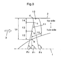
- Fig. 3 is a configuration diagram showing a fan rotating blade for a turbofan engine according to the invention.
- Reference numeral 1 denotes an engine rotary shaft (fan rotary shaft)
- Reference numeral 2 denotes a casing inner diameter
- Reference numeral 3 denotes an intake air flow.
- a fan rotating blade 10 according to the invention is a fan first-stage rotating blade, and a leading edge part 11 is formed by a vertical hub portion 12, a backward inclined mid-span portion 13, and a forward inclined tip portion 14.
- the vertical hub portion 12 is positioned on the hub side so as to be substantially perpendicular to the fan rotary shaft 1. In this example, it is desirable that the vertical hub portion 12 extends from an inner end position a of 0% to an outer end position b in a range of 40% to 50% with respect to a total radial span Ls of the leading edge part 11. Additionally, the vertical hub portion 12 is positioned within an angular rage of ⁇ 5° with respect to a plane perpendicular to the fan rotary shaft 1. That is, in this drawing, an angle ⁇ 1 is in a range of 85° to 95°.
- the backward mid-span portion 13 is positioned at the mid-span in the middle of the hub side and the tip side so as to be inclined to the downstream side from the hub side to the mid-span portion.
- the backward inclined mid-span portion 13 extends from an inner end position b in a range of 40% to 50% to an outer end position c in a range of 75% to 85% with respect to the total radial span Ls of the leading edge part 11.
- an outside is inclined backward in a range of 5° to 45° with respect to a plane perpendicular to the fan rotary shaft 1. That is, in this drawing, an angle ⁇ 2 is in a range of 45° to 85°.
- the forward inclined tip portion 14 is positioned on a tip side so as to be inclined toward the downstream side from the mid-span side to the tip portion. In this example, it is desirable that the forward inclined tip portion 14 extends from an inner end position c in a range of 75% to 85% to an outer end position d of 100% with respect to the total radial span Ls of the leading edge part 11. Additionally, an outside of the forward inclined tip portion 14 is inclined forward in a range of 15° to 30° with respect to a plane perpendicular to the fan rotary shaft 1. That is, in this drawing, an angle ⁇ 3 is in a range of 95° to 135°.
- FIGs. 4A and 4B are explanatory diagrams showing the vertical hub portion shown in Fig. 3 .
- Figs. 4A and 4B show a hub portion 12' different from the vertical hub portion according to the invention.
- Fig. 4A shows a case in which the hub portion 12' is inclined to the upstream side with respect to the fan rotary shaft 1, where a chord length 15 is long and heavy and a stress is large at a root (position a) of the leading edge part 11.
- Fig. 4B shows a case in which the hub portion 12' is inclined to the downstream side with respect to the fan rotary shaft 1, where the chord length 15 is short, a pressure ratio is small, and a flow rate is small.
- Fig. 5 is an explanatory diagram showing the backward inclined mid-span portion shown in Fig. 3 .
- This drawing shows a case in which the backward inclined mid-span portion is different from that of the invention and a mid-span portion 13' is inclined to the upstream side with respect to a hub-side path surface. That is, in this drawing, an angle ⁇ 2 is in a range of 95° to 135°. In this case, sine a blade center 16' of gravity moves to the upstream side, the stress at the root (position a) of the leading edge part 11 is large.
- Fig. 6 is an explanatory diagram showing a forward inclined tip portion shown in Fig. 3 .
- This drawing shows a case in which the forward inclined tip portion is different from that of the invention and a tip portion 14' is inclined to the downstream side with respect to the fan rotary shaft 1. That is, in this drawing, an angle ⁇ 3 is in a range of 45° to 85°. In this case, since an axial speed on the tip side is large, a loss of a shock wave is large.
- Fig. 7 is a diagram showing an embodiment of the fan rotating blade according to the invention.
- This drawing shows a simulation result (CFD calculation result) using a computer.
- CFD means Computer Fluid Dynamics.
- a horizontal axis denotes a pressure ratio and a vertical axis denotes a span ratio from the hub.
- this example shows a case in which an outer end position b of the vertical hub portion 12 is about 50% and an outer end position c of the backward inclined mid-span portion 13 is about 80% with respect to the total radial span Ls of the leading edge part.
- the pressure ratio of the invention is larger than that of the conventional art in a span ratio of 0 to 50%. That is, as a CFD calculation result, the result shows that the flow rate for each sectional area is larger by 5% or so and the pressure ratio on the hub side is larger by 20% or so than the fan rotating blade according to the conventional art having the same fan diameter.
- the rotating blade according to the invention is not limited by a degree of a bypass ratio, but can be applied in a case where the bypass ratio is small (for example, 1 or less) as well as a case where the bypass ratio is large (for example, 5 or more). That is, since it is possible to increase an air flow rate of a fan first-stage rotating blade without enlarging the fan first-stage rotating blade and a diameter of a casing surrounding the fan first-stage rotating blade even in an engine having a small bypass ratio, it is possible to reduce the weight. Additionally, it is possible to more increase the pressure ratio on the hub side than that of the fan rotating blade according to the conventional art.
Landscapes
- Engineering & Computer Science (AREA)
- Mechanical Engineering (AREA)
- General Engineering & Computer Science (AREA)
- Physics & Mathematics (AREA)
- Fluid Mechanics (AREA)
- Structures Of Non-Positive Displacement Pumps (AREA)
Abstract
Description
- The present invention relates to a fan rotating blade for a turbofan engine.
-
Fig. 1 is a schematic configuration diagram showing an aircraft engine 51 (a turbojet engine). As shown in this drawing, the turbojet engine is provided with afan 52 for taking air thereinto, acompressor 53 for compressing the intake air, acombustor 54 for burning a fuel by the compressed air, aturbine 55 for driving thefan 52 and thecompressor 53 by a combustion gas of thecombustor 54, an afterburner 56 for afterburning to increase a thrust, and the like. - In the invention, a pressure ratio indicates a total downstream pressure/a total upstream pressure of a blade. Additionally, a bypass ratio indicates a value obtained by dividing a flow rate on a bypass side (air directly passing through a nozzle to be discharged to the outside of the engine) by a flow rate on a core side (a flow toward the combustor via the compressor) at the downstream of the fan rotating blade.
- The turbojet engine in which the
fan 52 taking the air thereinto is enlarged in size and a bypass ratio is enlarged is called as "turbofan engine". The bypass ratio corresponds to a flow rate ratio (bypass flow/core flow) between an air flow (a core flow) flowing into a core engine (thecompressor 53, thecombustor 54, and theturbine 55 described above) and a bypass flow bypassing them. There is obtained an effect of reducing a flow speed of an exhaust jet and lowering noise and fuel consumption, in accordance with an increase of the ratio. - However, in the above-described turbofan engine, a problem arises in that a fan first-stage rotating blade (an up-front fan) and an inner diameter of a casing surrounding the fan first-stage rotating blade are enlarged by enlarging the bypass ratio, and a weight of the engine is increased.
- In order to solve the problem, there are already disclosed fan rotating blades having various shapes capable of increasing the flow rate of air introduced from the outside without increasing the inner diameter of the casing (
Patent Documents 1 to 6:Figs. 2A to 2F ). -
- [Patent Document 1]
US Patent No. 6328533B1 "SWEPT BARREL AIRFOIL" - [Patent Document 2]
US Patent No. 6071077 "SWEPT FAN BLADE" - [Patent Document 3]
US Patent No. RE38040E "SWEPT TURBOMACHINERY BLADE" - [Patent Document 4]
US Patent No. 5167489 "FORWARD SWEPT ROTOR BLADE" - [Patent Document 5]
US Patent No. 5725354 "FORWARD SWEPT FAN BLADE" - [Patent Document 6]
US Patent No. 6358003 B2 "ROTOR BLADE AN AXIAL-FLOW ENGINE" - As described above, in the turbofan engine according to the conventional art, a problem arises in that the fan first-stage rotating blade (the up-front fan) and the inner diameter of the casing surrounding the fan first-stage rotating blade are enlarged by enlarging the bypass ratio, and the weight of the engine is increased.
- Additionally, in the fan first-stage rotating blade according to the conventional art, for example, when a rotary speed is increased in order to increase an amount of air introduced from the outside, a circumferential speed increases too much, thereby causing a problem in that a loss of a shock wave excessively increases at a high flow rate.
- The present invention is contrived to solve the above-described problems. That is, an object of the invention is to provide a fan rotating blade for a turbofan engine capable of increasing a bypass ratio by increasing an intake air flow rate without enlarging a diameter of a fan and an inner diameter of a casing and of realizing a decrease in weight of an engine as well as a decrease in fuel consumption and noise.
- According to the invention, there is provided a fan rotating blade for a turbofan engine including: a leading edge part provided with a vertical hub portion positioned on the hub side so as to be substantially perpendicular to a fan rotary shaft, a backward mid-span portion inclined toward the downstream side from the hub side to the mid-span portion, and a forward inclined tip portion inclined toward the upstream side from the mid-span side to the tip portion.
- According to a preferred embodiment of the invention, the vertical hub portion extends from an inner end position of 0% to an outer end position in a rage of 20% to 50% with respect to a total radial span of the leading edge part and is positioned within a range of ±5° with respect to a plane perpendicular to the fan rotary shaft.
- Also, the backward inclined mid-span portion extends from an inner end position in a range of 20% to 50% to an outer end position in a range of 60% to 90% with respect to a total radial span of the leading edge part and its outside is inclined backward in a range of 5° to 45° with respect to a plane perpendicular to the fan rotary shaft.
- Also, the forward inclined tip portion extends from an inner end position in a range of 60% to 90% to an outer end position of 100% with respect to a total radial span of the leading edge part and its outside is inclined forward in a range of 5° to 45° with respect to a plane perpendicular to the fan rotary shaft.
- With the above-described configuration according to the invention, since the vertical hub portion on the hub side of the leading edge part is substantially perpendicular to the fan rotary shaft, a weight of the blade is smaller than a case in which the hub portion is inclined toward the upstream side, thereby particularly reducing a stress at the root of the leading edge part. Also, since a chord length is longer than a case in which the hub portion is inclined toward the downstream side, it is possible to increase a pressure ratio. Additionally, at the same time, when the chord length is long, a large flow is received on the hub side, thereby increasing a flow rate in the same engine front-surface area.
- Also, since the outside of the backward inclined mid-span portion positioned at the mid-span is inclined backward with respect to the plane perpendicular to the fan rotary shaft, a blade center of gravity is more positioned on the downstream side than a case in which the outside is inclined forward (forward inclination), thereby particularly reducing a stress at the leading edge part on the hub side.
- Also, since the outside of the forward inclined tip portion on the tip side is inclined forward, an inflow speed on the tip side is smaller than a case in which the outside is inclined backward (backward inclination), thereby reducing a loss of a shock wave.
- Therefore, in a turbofan engine having a large bypass ratio, it is possible to increase an air flow rate of a fan first-stage rotating blade without enlarging the fan first-stage rotating blade and a diameter of a casing surrounding the fan first-stage rotating blade. Accordingly, since a bypass ratio is increased, it is possible to realize a decrease in fuel consumption and noise and to reduce a weight. Additionally, it is possible to more increase a pressure ratio on the hub side than the fan rotating blade according to the conventional art.
-
- [
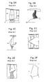
Fig. 1] Fig. 1 is a configuration diagram showing a turbofan engine according to a conventional art. - [
Fig. 2A] Fig. 2A is a schematic diagram showing a fan rotating blade shown inPatent Document 1. - [
Fig. 2B] Fig. 2B is a schematic diagram showing a fan rotating blade shown inPatent Document 2. - [
Fig. 2C] Fig. 2C is a schematic diagram showing a fan rotating blade shown inPatent Document 3. - [
Fig. 2D] Fig. 2D is a schematic diagram showing a fan rotating blade shown in Patent Document 4. - [
Fig. 2E] Fig. 2E is a schematic diagram showing a fan rotating blade shown in Patent Document 5. - [
Fig. 2F] Fig. 2F is a schematic diagram showing a fan rotating blade shown in Patent Document 6. - [
Fig. 3] Fig. 3 is a configuration diagram showing a fan rotating blade for a turbofan engine according to the invention. - [
Fig. 4A] Fig. 4A is an explanatory diagram showing a vertical hub shown inFig. 3 . - [
Fig. 4B] Fig. 4B is another explanatory diagram showing a vertical hub shown inFig. 3 . - [
Fig. 5] Fig. 5 is an explanatory diagram showing a backward inclined mid-span portion shown inFig. 3 . - [
Fig. 6] Fig. 6 is an explanatory diagram showing a forward inclined tip portion shown inFig. 3 . - [
Fig. 7] Fig. 7 is a CFD calculation result showing an embodiment of the invention. - Hereinafter, a preferred embodiment of the invention will be described with reference to the drawings. Also, in the respective drawings, the same reference numerals are given to the same components and the repetitive description thereof will be omitted.
Fig. 3 is a configuration diagram showing a fan rotating blade for a turbofan engine according to the invention. In this drawing,Reference numeral 1 denotes an engine rotary shaft (fan rotary shaft),Reference numeral 2 denotes a casing inner diameter, andReference numeral 3 denotes an intake air flow.
It is desirable that afan rotating blade 10 according to the invention is a fan first-stage rotating blade, and aleading edge part 11 is formed by avertical hub portion 12, a backward inclinedmid-span portion 13, and a forwardinclined tip portion 14. - The
vertical hub portion 12 is positioned on the hub side so as to be substantially perpendicular to thefan rotary shaft 1.
In this example, it is desirable that thevertical hub portion 12 extends from an inner end position a of 0% to an outer end position b in a range of 40% to 50% with respect to a total radial span Ls of theleading edge part 11. Additionally, thevertical hub portion 12 is positioned within an angular rage of ±5° with respect to a plane perpendicular to thefan rotary shaft 1. That is, in this drawing, an angle θ1 is in a range of 85° to 95°. - The backward
mid-span portion 13 is positioned at the mid-span in the middle of the hub side and the tip side so as to be inclined to the downstream side from the hub side to the mid-span portion.
In this example, it is desirable that the backward inclinedmid-span portion 13 extends from an inner end position b in a range of 40% to 50% to an outer end position c in a range of 75% to 85% with respect to the total radial span Ls of theleading edge part 11. Additionally, in the backward inclinedmid-span portion 13, an outside is inclined backward in a range of 5° to 45° with respect to a plane perpendicular to thefan rotary shaft 1. That is, in this drawing, an angle θ2 is in a range of 45° to 85°. - The forward
inclined tip portion 14 is positioned on a tip side so as to be inclined toward the downstream side from the mid-span side to the tip portion.
In this example, it is desirable that the forwardinclined tip portion 14 extends from an inner end position c in a range of 75% to 85% to an outer end position d of 100% with respect to the total radial span Ls of theleading edge part 11. Additionally, an outside of the forwardinclined tip portion 14 is inclined forward in a range of 15° to 30° with respect to a plane perpendicular to thefan rotary shaft 1. That is, in this drawing, an angle θ3 is in a range of 95° to 135°. -
Figs. 4A and 4B are explanatory diagrams showing the vertical hub portion shown inFig. 3 . In this drawing,Figs. 4A and 4B show a hub portion 12' different from the vertical hub portion according to the invention.
Fig. 4A shows a case in which the hub portion 12' is inclined to the upstream side with respect to thefan rotary shaft 1, where achord length 15 is long and heavy and a stress is large at a root (position a) of theleading edge part 11.
Additionally,Fig. 4B shows a case in which the hub portion 12' is inclined to the downstream side with respect to thefan rotary shaft 1, where thechord length 15 is short, a pressure ratio is small, and a flow rate is small. - On the contrary, in this invention, since the
vertical hub portion 12 on the hub side is substantially perpendicular to thefan rotary shaft 1, a weight of the blade is smaller than a case in which the hub portion is inclined toward the upstream side (Fig. 4A ), thereby particularly reducing the stress at the root (position a) of theleading edge part 11.
Additionally, since thechord length 15 is longer than a case in which the hub portion is inclined toward the downstream side (Fig. 4B ), it is possible to increase the pressure ratio.
Then, at the same time, when thechord length 15 is long, a large flow is received on the hub side, thereby increasing the flow rate in the same engine front-surface area. -
Fig. 5 is an explanatory diagram showing the backward inclined mid-span portion shown inFig. 3 . This drawing shows a case in which the backward inclined mid-span portion is different from that of the invention and a mid-span portion 13' is inclined to the upstream side with respect to a hub-side path surface. That is, in this drawing, an angle θ2 is in a range of 95° to 135°.
In this case, sine a blade center 16' of gravity moves to the upstream side, the stress at the root (position a) of theleading edge part 11 is large. - On the contrary, in this invention, since the outside of the backward inclined
mid-span portion 13 positioned at the mid-span is inclined backward with respect to the plane perpendicular to thefan rotary shaft 1, ablade center 16 of gravity is more positioned on the downstream side than a case in which the outside is inclined forward (forward inclination) (Fig. 5 ), thereby particularly reducing the stress at the leading edge part (position a) on the hub side. -
Fig. 6 is an explanatory diagram showing a forward inclined tip portion shown inFig. 3 . This drawing shows a case in which the forward inclined tip portion is different from that of the invention and a tip portion 14' is inclined to the downstream side with respect to thefan rotary shaft 1. That is, in this drawing, an angle θ3 is in a range of 45° to 85°.
In this case, since an axial speed on the tip side is large, a loss of a shock wave is large. - On the contrary, in this invention, since the outside of the forward
inclined tip portion 14 on the tip side is inclined forward, an inflow speed on the tip side is smaller than a case in which the outside is inclined backward (backward inclination) (Fig. 6 ), thereby reducing a loss of a shock wave. -
Fig. 7 is a diagram showing an embodiment of the fan rotating blade according to the invention. This drawing shows a simulation result (CFD calculation result) using a computer. CFD means Computer Fluid Dynamics.
In this drawing, a horizontal axis denotes a pressure ratio and a vertical axis denotes a span ratio from the hub. Additionally, this example shows a case in which an outer end position b of thevertical hub portion 12 is about 50% and an outer end position c of the backward inclinedmid-span portion 13 is about 80% with respect to the total radial span Ls of the leading edge part. - From this drawing, it is obviously understood that the pressure ratio of the invention is larger than that of the conventional art in a span ratio of 0 to 50%.
That is, as a CFD calculation result, the result shows that the flow rate for each sectional area is larger by 5% or so and the pressure ratio on the hub side is larger by 20% or so than the fan rotating blade according to the conventional art having the same fan diameter. - Additionally, the invention is not limited to the above-described embodiment, but can be, of course, modified into various forms without departing from the spirit of the invention.
For example, the rotating blade according to the invention is not limited by a degree of a bypass ratio, but can be applied in a case where the bypass ratio is small (for example, 1 or less) as well as a case where the bypass ratio is large (for example, 5 or more).
That is, since it is possible to increase an air flow rate of a fan first-stage rotating blade without enlarging the fan first-stage rotating blade and a diameter of a casing surrounding the fan first-stage rotating blade even in an engine having a small bypass ratio, it is possible to reduce the weight. Additionally, it is possible to more increase the pressure ratio on the hub side than that of the fan rotating blade according to the conventional art.
Claims (4)
- A fan rotating blade for a turbofan engine comprising:a leading edge part provided with a vertical hub portion positioned on the hub side so as to be substantially perpendicular to a fan rotary shaft, a backward mid-span portion inclined toward the downstream side from the hub side to the mid-span portion, and a forward inclined tip portion inclined toward the upstream side from the mid-span side to the tip portion.
- The fan rotating blade for the turbofan engine according to Claim 1, wherein the vertical hub portion extends from an inner end position of 0% to an outer end position in a rage of 20% to 50% with respect to a total radial span of the leading edge part and is positioned within a range of ±5° with respect to a plane perpendicular to the fan rotary shaft.
- The fan rotating blade for the turbofan engine according to Claim 1, wherein the backward inclined mid-span portion extends from an inner end position in a range of 20% to 50% to an outer end position in a range of 60% to 90% with respect to a total radial span of the leading edge part and its outside is inclined backward in a range of 5° to 45° with respect to a plane perpendicular to the fan rotary shaft.
- The fan rotating blade for the turbofan engine according to Claim 1, wherein the forward inclined tip portion extends from an inner end position in a range of 60% to 90% to an outer end position of 100% with respect to a total radial span of the leading edge part and its outside is inclined forward in a range of 5° to 45° with respect to a plane perpendicular to the fan rotary shaft.
Applications Claiming Priority (2)
| Application Number | Priority Date | Filing Date | Title |
|---|---|---|---|
| JP2006146319A JP4863162B2 (en) | 2006-05-26 | 2006-05-26 | Fan blade of turbofan engine |
| PCT/JP2007/056169 WO2007138779A1 (en) | 2006-05-26 | 2007-03-26 | Moving blade of turbofan engine |
Publications (2)
| Publication Number | Publication Date |
|---|---|
| EP2022988A1 true EP2022988A1 (en) | 2009-02-11 |
| EP2022988A4 EP2022988A4 (en) | 2014-03-05 |
Family
ID=38778304
Family Applications (1)
| Application Number | Title | Priority Date | Filing Date |
|---|---|---|---|
| EP07739607.5A Withdrawn EP2022988A4 (en) | 2006-05-26 | 2007-03-26 | Moving blade of turbofan engine |
Country Status (5)
| Country | Link |
|---|---|
| US (1) | US8186962B2 (en) |
| EP (1) | EP2022988A4 (en) |
| JP (1) | JP4863162B2 (en) |
| CA (1) | CA2650511C (en) |
| WO (1) | WO2007138779A1 (en) |
Cited By (9)
| Publication number | Priority date | Publication date | Assignee | Title |
|---|---|---|---|---|
| CN102483072A (en) * | 2009-09-04 | 2012-05-30 | 西门子公司 | Compressor blade for an axial compressor |
| RU2460905C2 (en) * | 2010-07-29 | 2012-09-10 | Открытое акционерное общество "Национальный институт авиационных технологий" (ОАО НИАТ) | Axial-flow fan or compressor impeller and fan of bypass fanjet incorporating said impeller |
| EP2921648A1 (en) * | 2014-03-20 | 2015-09-23 | Alstom Technology Ltd | Gas turbine blade comprising bended leading and trailing edges |
| GB2555567A (en) * | 2016-09-21 | 2018-05-09 | Cummins Ltd | Turbine wheel for a turbo-machine |
| EP3372786A1 (en) * | 2017-03-09 | 2018-09-12 | Honeywell International Inc. | High-pressure compressor rotor blade with leading edge having indent segment |
| EP3379029A1 (en) * | 2017-03-22 | 2018-09-26 | Pratt & Whitney Canada Corp. | Fan rotor with flow induced resonance control |
| EP3379028A1 (en) * | 2017-02-22 | 2018-09-26 | Honeywell International Inc. | Core-protecting fan modules and turbofan engines containing the same |
| EP3379030A1 (en) * | 2017-03-22 | 2018-09-26 | Pratt & Whitney Canada Corp. | Fan rotor with flow induced resonance control |
| EP3825556A1 (en) * | 2019-11-22 | 2021-05-26 | Pratt & Whitney Canada Corp. | Impeller with hub sweep |
Families Citing this family (32)
| Publication number | Priority date | Publication date | Assignee | Title |
|---|---|---|---|---|
| JP5703750B2 (en) | 2010-12-28 | 2015-04-22 | 株式会社Ihi | Fan blade and fan |
| US9790797B2 (en) * | 2011-07-05 | 2017-10-17 | United Technologies Corporation | Subsonic swept fan blade |
| FR2983234B1 (en) * | 2011-11-29 | 2014-01-17 | Snecma | AUBE FOR TURBOMACHINE MONOBLOC AUBING DISK |
| EP2669475B1 (en) * | 2012-06-01 | 2018-08-01 | Safran Aero Boosters SA | S-shaped profile blade of axial turbomachine compressor, corresponding compressor and turbomachine |
| US9212663B2 (en) * | 2013-01-28 | 2015-12-15 | Terrence O'Neill | All-supersonic ducted fan for propelling aircraft at high subsonic speeds |
| EP3575551B1 (en) | 2014-02-19 | 2021-10-27 | Raytheon Technologies Corporation | Gas turbine engine airfoil |
| US9567858B2 (en) | 2014-02-19 | 2017-02-14 | United Technologies Corporation | Gas turbine engine airfoil |
| WO2015126824A1 (en) | 2014-02-19 | 2015-08-27 | United Technologies Corporation | Gas turbine engine airfoil |
| WO2015126451A1 (en) * | 2014-02-19 | 2015-08-27 | United Technologies Corporation | Gas turbine engine airfoil |
| EP3108100B1 (en) | 2014-02-19 | 2021-04-14 | Raytheon Technologies Corporation | Gas turbine engine fan blade |
| WO2015126454A1 (en) | 2014-02-19 | 2015-08-27 | United Technologies Corporation | Gas turbine engine airfoil |
| US10465702B2 (en) | 2014-02-19 | 2019-11-05 | United Technologies Corporation | Gas turbine engine airfoil |
| EP3108120B1 (en) | 2014-02-19 | 2021-03-31 | Raytheon Technologies Corporation | Gas turbine engine having a geared architecture and a specific fixed airfoil structure |
| WO2015126774A1 (en) | 2014-02-19 | 2015-08-27 | United Technologies Corporation | Gas turbine engine airfoil |
| US10557477B2 (en) | 2014-02-19 | 2020-02-11 | United Technologies Corporation | Gas turbine engine airfoil |
| US10422226B2 (en) | 2014-02-19 | 2019-09-24 | United Technologies Corporation | Gas turbine engine airfoil |
| EP3108118B1 (en) | 2014-02-19 | 2019-09-18 | United Technologies Corporation | Gas turbine engine airfoil |
| EP3108115B8 (en) | 2014-02-19 | 2023-11-08 | RTX Corporation | Turbofan engine with geared architecture and lpc blades |
| WO2015175044A2 (en) | 2014-02-19 | 2015-11-19 | United Technologies Corporation | Gas turbine engine airfoil |
| US9140127B2 (en) | 2014-02-19 | 2015-09-22 | United Technologies Corporation | Gas turbine engine airfoil |
| EP3108123B1 (en) | 2014-02-19 | 2023-10-04 | Raytheon Technologies Corporation | Turbofan engine with geared architecture and lpc airfoils |
| US9163517B2 (en) | 2014-02-19 | 2015-10-20 | United Technologies Corporation | Gas turbine engine airfoil |
| US10385866B2 (en) | 2014-02-19 | 2019-08-20 | United Technologies Corporation | Gas turbine engine airfoil |
| EP3108121B1 (en) | 2014-02-19 | 2023-09-06 | Raytheon Technologies Corporation | Turbofan engine with geared architecture and lpc airfoils |
| WO2015126449A1 (en) | 2014-02-19 | 2015-08-27 | United Technologies Corporation | Gas turbine engine airfoil |
| US10584715B2 (en) | 2014-02-19 | 2020-03-10 | United Technologies Corporation | Gas turbine engine airfoil |
| EP3108119B1 (en) | 2014-02-19 | 2023-10-04 | RTX Corporation | Turbofan engine with geared architecture and lpc blade airfoils |
| RU2606294C1 (en) * | 2015-07-06 | 2017-01-10 | Федеральное государственное унитарное предприятие "Центральный институт авиационного моторостроения имени П.И. Баранова" | High-speed axial fan impeller |
| CA2958459A1 (en) | 2016-02-19 | 2017-08-19 | Pratt & Whitney Canada Corp. | Compressor rotor for supersonic flutter and/or resonant stress mitigation |
| GB201702383D0 (en) * | 2017-02-14 | 2017-03-29 | Rolls Royce Plc | Gas turbine engine fan blade with axial lean |
| JP6789414B2 (en) * | 2017-12-26 | 2020-11-25 | 三菱電機株式会社 | Axial blower and ceiling fan |
| GB202014015D0 (en) | 2020-09-07 | 2020-10-21 | Rolls Royce Plc | Aircraft engine |
Citations (2)
| Publication number | Priority date | Publication date | Assignee | Title |
|---|---|---|---|---|
| US2160467A (en) * | 1937-09-22 | 1939-05-30 | Edgar T Ward | Propeller |
| EP1557530A2 (en) * | 2004-01-26 | 2005-07-27 | United Technologies Corporation | Hollow fan blade for gas turbine engine |
Family Cites Families (13)
| Publication number | Priority date | Publication date | Assignee | Title |
|---|---|---|---|---|
| US5167489A (en) | 1991-04-15 | 1992-12-01 | General Electric Company | Forward swept rotor blade |
| US5642985A (en) | 1995-11-17 | 1997-07-01 | United Technologies Corporation | Swept turbomachinery blade |
| US6071077A (en) | 1996-04-09 | 2000-06-06 | Rolls-Royce Plc | Swept fan blade |
| US5725354A (en) | 1996-11-22 | 1998-03-10 | General Electric Company | Forward swept fan blade |
| US5947688A (en) * | 1997-12-22 | 1999-09-07 | General Electric Company | Frequency tuned hybrid blade |
| US5913661A (en) * | 1997-12-22 | 1999-06-22 | General Electric Company | Striated hybrid blade |
| DE19812624A1 (en) | 1998-03-23 | 1999-09-30 | Bmw Rolls Royce Gmbh | Rotor blade of an axial flow machine |
| US6328533B1 (en) | 1999-12-21 | 2001-12-11 | General Electric Company | Swept barrel airfoil |
| FR2851798B1 (en) * | 2003-02-27 | 2005-04-29 | Snecma Moteurs | TURBOREACTOR TURBINE BOW |
| US6905309B2 (en) * | 2003-08-28 | 2005-06-14 | General Electric Company | Methods and apparatus for reducing vibrations induced to compressor airfoils |
| US7070391B2 (en) * | 2004-01-26 | 2006-07-04 | United Technologies Corporation | Hollow fan blade for gas turbine engine |
| EP1580399B1 (en) * | 2004-03-25 | 2006-11-15 | Rolls-Royce Deutschland Ltd & Co KG | Compressor for an aircraft engine. |
| JP4179216B2 (en) * | 2004-04-28 | 2008-11-12 | 株式会社Ihi | Turbofan engine |
-
2006
- 2006-05-26 JP JP2006146319A patent/JP4863162B2/en active Active
-
2007
- 2007-03-26 EP EP07739607.5A patent/EP2022988A4/en not_active Withdrawn
- 2007-03-26 US US12/300,277 patent/US8186962B2/en active Active
- 2007-03-26 WO PCT/JP2007/056169 patent/WO2007138779A1/en active Application Filing
- 2007-03-26 CA CA2650511A patent/CA2650511C/en active Active
Patent Citations (2)
| Publication number | Priority date | Publication date | Assignee | Title |
|---|---|---|---|---|
| US2160467A (en) * | 1937-09-22 | 1939-05-30 | Edgar T Ward | Propeller |
| EP1557530A2 (en) * | 2004-01-26 | 2005-07-27 | United Technologies Corporation | Hollow fan blade for gas turbine engine |
Non-Patent Citations (1)
| Title |
|---|
| See also references of WO2007138779A1 * |
Cited By (23)
| Publication number | Priority date | Publication date | Assignee | Title |
|---|---|---|---|---|
| US8911215B2 (en) | 2009-09-04 | 2014-12-16 | Siemens Aktiengesellschaft | Compressor blade for an axial compressor |
| CN102483072A (en) * | 2009-09-04 | 2012-05-30 | 西门子公司 | Compressor blade for an axial compressor |
| RU2460905C2 (en) * | 2010-07-29 | 2012-09-10 | Открытое акционерное общество "Национальный институт авиационных технологий" (ОАО НИАТ) | Axial-flow fan or compressor impeller and fan of bypass fanjet incorporating said impeller |
| EP2921648B1 (en) | 2014-03-20 | 2018-12-26 | Ansaldo Energia Switzerland AG | Gas turbine blade comprising bended leading and trailing edges |
| EP2921648A1 (en) * | 2014-03-20 | 2015-09-23 | Alstom Technology Ltd | Gas turbine blade comprising bended leading and trailing edges |
| CN104929696A (en) * | 2014-03-20 | 2015-09-23 | 阿尔斯通技术有限公司 | Gas turbine blade |
| EP2921647A1 (en) * | 2014-03-20 | 2015-09-23 | Alstom Technology Ltd | Gas turbine blade comprising bended leading and trailing edges |
| US9765626B2 (en) | 2014-03-20 | 2017-09-19 | Ansaldo Energia Switzerland AG | Gas turbine blade |
| RU2723658C2 (en) * | 2014-03-20 | 2020-06-17 | Ансалдо Энерджиа Свитзерлэнд Аг | Gas turbine blade |
| GB2555567A (en) * | 2016-09-21 | 2018-05-09 | Cummins Ltd | Turbine wheel for a turbo-machine |
| US10941662B2 (en) | 2016-09-21 | 2021-03-09 | Cummins Ltd. | Turbine wheel for a turbo-machine |
| EP3379028A1 (en) * | 2017-02-22 | 2018-09-26 | Honeywell International Inc. | Core-protecting fan modules and turbofan engines containing the same |
| US10670040B2 (en) | 2017-02-22 | 2020-06-02 | Honeywell International Inc. | Core-protecting fan modules and turbofan engines containing the same |
| US10718214B2 (en) | 2017-03-09 | 2020-07-21 | Honeywell International Inc. | High-pressure compressor rotor with leading edge having indent segment |
| EP3372786A1 (en) * | 2017-03-09 | 2018-09-12 | Honeywell International Inc. | High-pressure compressor rotor blade with leading edge having indent segment |
| EP3379030A1 (en) * | 2017-03-22 | 2018-09-26 | Pratt & Whitney Canada Corp. | Fan rotor with flow induced resonance control |
| US10458436B2 (en) | 2017-03-22 | 2019-10-29 | Pratt & Whitney Canada Corp. | Fan rotor with flow induced resonance control |
| US10480535B2 (en) | 2017-03-22 | 2019-11-19 | Pratt & Whitney Canada Corp. | Fan rotor with flow induced resonance control |
| US10634169B2 (en) | 2017-03-22 | 2020-04-28 | Pratt & Whitney Canada Corp. | Fan rotor with flow induced resonance control |
| EP3379029A1 (en) * | 2017-03-22 | 2018-09-26 | Pratt & Whitney Canada Corp. | Fan rotor with flow induced resonance control |
| US11035385B2 (en) | 2017-03-22 | 2021-06-15 | Pratt & Whitney Canada Corp. | Fan rotor with flow induced resonance control |
| EP3825556A1 (en) * | 2019-11-22 | 2021-05-26 | Pratt & Whitney Canada Corp. | Impeller with hub sweep |
| US12018583B2 (en) | 2019-11-22 | 2024-06-25 | Pratt & Whitney Canada Corp. | Impeller with hub sweep |
Also Published As
| Publication number | Publication date |
|---|---|
| US8186962B2 (en) | 2012-05-29 |
| CA2650511A1 (en) | 2007-12-06 |
| JP2007315303A (en) | 2007-12-06 |
| CA2650511C (en) | 2012-10-16 |
| EP2022988A4 (en) | 2014-03-05 |
| WO2007138779A1 (en) | 2007-12-06 |
| JP4863162B2 (en) | 2012-01-25 |
| US20100232970A1 (en) | 2010-09-16 |
Similar Documents
| Publication | Publication Date | Title |
|---|---|---|
| CA2650511C (en) | Fan rotating blade for turbofan engine | |
| US10718216B2 (en) | Airfoil for gas turbine engine | |
| CA2564242C (en) | Turbofan engine | |
| EP2037126A1 (en) | Tubofan engine | |
| EP2738392A2 (en) | Fan blade for a turbofan gas turbine engine | |
| EP3187712B1 (en) | Nacelle short inlet | |
| CN105736460B (en) | Axial compressor rotor incorporating non-axisymmetric hub flowpath and splitter blades | |
| EP3098383B1 (en) | Compressor airfoil with compound leading edge profile | |
| US20210372288A1 (en) | Compressor stator with leading edge fillet | |
| EP3159512A1 (en) | Improved crosswind performance aircraft engine spinner | |
| US20210270137A1 (en) | Turbine engine with airfoil having high acceleration and low blade turning | |
| JP4143901B2 (en) | Turbofan engine | |
| CA2846376C (en) | Turbo-machinery rotors with rounded tip edge | |
| EP3170973B1 (en) | Turbine engine flow path | |
| CA2827566C (en) | Airfoil with tip extension for gas turbine engine | |
| US11506059B2 (en) | Compressor impeller with partially swept leading edge surface | |
| JP4974006B2 (en) | Turbofan engine | |
| US20240254883A1 (en) | Turbine airfoils | |
| EP3951188A1 (en) | Compressor impeller with partially swept leading edge surface | |
| JP2021008820A (en) | Aircraft gas turbin |
Legal Events
| Date | Code | Title | Description |
|---|---|---|---|
| PUAI | Public reference made under article 153(3) epc to a published international application that has entered the european phase |
Free format text: ORIGINAL CODE: 0009012 |
|
| 17P | Request for examination filed |
Effective date: 20081105 |
|
| AK | Designated contracting states |
Kind code of ref document: A1 Designated state(s): AT BE BG CH CY CZ DE DK EE ES FI FR GB GR HU IE IS IT LI LT LU LV MC MT NL PL PT RO SE SI SK TR |
|
| AX | Request for extension of the european patent |
Extension state: AL BA HR MK RS |
|
| DAX | Request for extension of the european patent (deleted) | ||
| RBV | Designated contracting states (corrected) |
Designated state(s): DE FR GB IT |
|
| A4 | Supplementary search report drawn up and despatched |
Effective date: 20140130 |
|
| RIC1 | Information provided on ipc code assigned before grant |
Ipc: F01D 5/14 20060101AFI20140124BHEP Ipc: F04D 29/32 20060101ALI20140124BHEP Ipc: F04D 29/38 20060101ALI20140124BHEP |
|
| 17Q | First examination report despatched |
Effective date: 20180314 |
|
| STAA | Information on the status of an ep patent application or granted ep patent |
Free format text: STATUS: THE APPLICATION IS DEEMED TO BE WITHDRAWN |
|
| 18D | Application deemed to be withdrawn |
Effective date: 20190514 |