EP2022658A1 - Straddle-type vehicle - Google Patents
Straddle-type vehicle Download PDFInfo
- Publication number
- EP2022658A1 EP2022658A1 EP08252530A EP08252530A EP2022658A1 EP 2022658 A1 EP2022658 A1 EP 2022658A1 EP 08252530 A EP08252530 A EP 08252530A EP 08252530 A EP08252530 A EP 08252530A EP 2022658 A1 EP2022658 A1 EP 2022658A1
- Authority
- EP
- European Patent Office
- Prior art keywords
- fan
- radiator
- section
- heat exchanger
- core
- Prior art date
- Legal status (The legal status is an assumption and is not a legal conclusion. Google has not performed a legal analysis and makes no representation as to the accuracy of the status listed.)
- Granted
Links
Images




Classifications
-
- B—PERFORMING OPERATIONS; TRANSPORTING
- B60—VEHICLES IN GENERAL
- B60K—ARRANGEMENT OR MOUNTING OF PROPULSION UNITS OR OF TRANSMISSIONS IN VEHICLES; ARRANGEMENT OR MOUNTING OF PLURAL DIVERSE PRIME-MOVERS IN VEHICLES; AUXILIARY DRIVES FOR VEHICLES; INSTRUMENTATION OR DASHBOARDS FOR VEHICLES; ARRANGEMENTS IN CONNECTION WITH COOLING, AIR INTAKE, GAS EXHAUST OR FUEL SUPPLY OF PROPULSION UNITS IN VEHICLES
- B60K11/00—Arrangement in connection with cooling of propulsion units
- B60K11/02—Arrangement in connection with cooling of propulsion units with liquid cooling
- B60K11/04—Arrangement or mounting of radiators, radiator shutters, or radiator blinds
-
- B—PERFORMING OPERATIONS; TRANSPORTING
- B62—LAND VEHICLES FOR TRAVELLING OTHERWISE THAN ON RAILS
- B62M—RIDER PROPULSION OF WHEELED VEHICLES OR SLEDGES; POWERED PROPULSION OF SLEDGES OR SINGLE-TRACK CYCLES; TRANSMISSIONS SPECIALLY ADAPTED FOR SUCH VEHICLES
- B62M7/00—Motorcycles characterised by position of motor or engine
- B62M7/02—Motorcycles characterised by position of motor or engine with engine between front and rear wheels
-
- B—PERFORMING OPERATIONS; TRANSPORTING
- B60—VEHICLES IN GENERAL
- B60Y—INDEXING SCHEME RELATING TO ASPECTS CROSS-CUTTING VEHICLE TECHNOLOGY
- B60Y2200/00—Type of vehicle
- B60Y2200/10—Road Vehicles
- B60Y2200/12—Motorcycles, Trikes; Quads; Scooters
- B60Y2200/126—Scooters
-
- B—PERFORMING OPERATIONS; TRANSPORTING
- B62—LAND VEHICLES FOR TRAVELLING OTHERWISE THAN ON RAILS
- B62K—CYCLES; CYCLE FRAMES; CYCLE STEERING DEVICES; RIDER-OPERATED TERMINAL CONTROLS SPECIALLY ADAPTED FOR CYCLES; CYCLE AXLE SUSPENSIONS; CYCLE SIDECARS, FORECARS, OR THE LIKE
- B62K2202/00—Motorised scooters
Definitions
- the present invention relates to a straddle-type vehicle that includes a heat exchanger having a plate-shaped core that contacts outside air, a fan that is disposed to face the core and takes or draws in outside air, and a fan case that covers the fan and is disposed at a predetermined distance away from the heat exchanger.
- a heat exchanger In straddle-type vehicles such as motorcycles having a water-cooled engine, a heat exchanger is typically provided in order to lower the temperature of engine coolant (water).
- Known heat exchangers have plate-shaped cores arranged to be contacted with outside air. Outside air passing through the core removes the heat of the coolant inside.
- straddle-type vehicles that include a heat exchanger like that described above
- a method that is widely used takes in outside air using a fan disposed to face the core of the heat exchanger.
- Such an arrangement is disclosed in, for example, JP-A-2005-119501 . This improves the ability of a heat exchanger unit, which includes the heat exchanger and the fan, to cool the coolant (hereinafter referred to as the "cooling ability").
- the fan is covered by a fan case.
- the fan case is fixed at a predetermined distance or clearance from the heat exchanger.
- the heat exchanger unit when the heat exchanger unit is positioned in a side of the vehicle, the running or traveling wind is less likely to hit the core of the heat exchanger, as compared to when the heat exchanger unit is positioned at the front of the vehicle. Therefore, it is desirable to improve the cooling ability of the heat exchanger unit, which can be achieved by using a fan to more reliably feed outside air taken in by the fan to the core of the heat exchanger.
- the invention has been devised in light of the above-described circumstances. It is an object of an embodiment of the invention to provide a straddle-type vehicle with a heat exchanger unit with an improved cooling ability.
- a straddle-type vehicle comprising:
- the closure section may be formed of an elastic member.
- the closure section may be adhesively attached to the edge section.
- the core may include a surface facing the fan and an opposing surface.
- the opposing surface may be positioned to face in a direction other than a forward direction of the vehicle.
- the opposing surface may be disposed to face toward an outside in a vehicle width direction.
- a diameter of the opening may be substantially the same as the outer diameter of the fan.
- a vehicle heat exchanger assembly comprising:
- a further aspect of the invention provides a heat exchanger including a plate-shaped core that contacts outside air; a fan that is disposed to face the core and takes in outside air; and a fan case that covers the fan.
- the fan case is fixed at a predetermined distance from the heat exchanger.
- An opening that faces the core is formed in the fan case.
- the fan case includes an edge section that surrounds an outer edge of the opening.
- the fan case or the heat exchanger includes a closure section that closes the gap between the edge section and the heat exchanger.
- the outside air taken in by the fan hardly passes through the gap between the edge section of the fan case and the heat exchanger.
- the outside air taken in by the fan can be more reliably fed to the core of the heat exchanger.
- the cooling ability of the heat exchanger unit is improved.
- the closure section may be formed of an elastic material, for example, urethane.
- the closure section may be adhesively attached to the edge section.
- the core may have an outside surface that is a surface on an opposite side of a surface that faces the fan.
- the outside surface may be positioned to face in a direction other than the forward direction of the vehicle.
- the outside surface may be disposed to face toward an outside in a vehicle width direction.
- a diameter of the opening may be substantially the same as the outer diameter of the fan.
- the outside air taken in by the fan can be more reliably introduced to the core of the heat exchanger.
- a heat exchanger unit with an improved cooling ability in a saddle type vehicle.
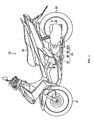
- FIG. 1 is a left side view of a motorcycle 10 according to the embodiment.
- the motorcycle 10 is an underbone motorcycle in which a body frame (not shown in the figures) is disposed at a lower location than that of a normal motorcycle.
- the motorcycle 10 includes a front wheel 21 and a rear wheel 22, and uses a swing type engine unit 40 to drive the rear wheel 22.
- the swing type engine unit 40 is provided below a seat 20 on which a rider sits, and extends in the front-rear direction of the vehicle.
- the swing type engine unit 40 includes a cylinder head 70, a cylinder 80 connected to the cylinder head 70, a crank case 90B (refer to FIG. 2 ) connected to the cylinder 80, and a transmission case 90A.
- the swing type engine unit 40 is provided with a radiator 60 on the right side of the vehicle.
- a water-cooled, single cylinder, four-stroke engine includes the cylinder head 70, the cylinder 80, and the radiator 60.
- the transmission case 90A houses a transmission unit (not shown in the figures).
- the transmission unit transmits power generated by the engine including the cylinder head 70 and the cylinder 80 to the rear wheel 22.
- An upper section of the transmission case 90A is provided with a cushion unit 23 that is fixed to the body frame.
- the body frame rotatably supports the lower side of a front section of the transmission case 90A.
- a rear section of the transmission case 90A can swing in the up-down direction of the vehicle.
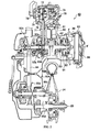
- FIG. 2 is a schematic cross sectional view of the swing type engine unit 40 along the line A-A in FIG. 1 . Note that hatching is omitted in FIG. 2 .
- the cylinder 80 is provided on a vehicle centerline that divides the vehicle width into two substantially equal halves.
- the cylinder 80 includes a piston 81 and a connecting rod 82.
- the piston 81 is inserted into the cylinder 80.
- the connecting rod 82 transmits the power of the piston 81 to a crank shaft 83.
- the crank case 90B houses the crank shaft 83 disposed in the vehicle width direction.
- the transmission case 90A houses a starter clutch 93a, a drive pulley 93b, a drive belt 94, a driven pulley 95a, a drive shaft 95c, a gear speed reduction mechanism 95d, etc.
- the starter clutch 93a is connected to the crank shaft 83 on the left side of the vehicle centerline.
- the starter clutch 93a is housed in a starter clutch housing 93c.
- the drive pulley 93b is connected to the crank shaft 83 on the left side of the starter clutch 93a.
- the driven pulley 95a is connected to the drive shaft 95c.
- the drive belt 94 is wound around the drive pulley 93b and the driven pulley 95a.
- the drive pulley 93b, the drive belt 94 and the driven pulley 95a form a V-belt type automatic transmission mechanism.
- a rear axle 25 is provided to the rear of the drive shaft 95c.
- the driving force of the crank shaft 83 is transmitted to the drive shaft 95c via the drive pulley 93b, the drive belt 94, and the driven pulley 95a, and then transmitted from the drive shaft 95c to the rear axle 25 via the gear speed reduction mechanism 95d.
- the cylinder head 70 includes a cam shaft 73 that extends in the vehicle width direction.
- a cam sprocket 72 is fixed to one end of the cam shaft 73.
- a cam chain 71 is wound around a crank sprocket 93d fixed to the crank shaft 83, and the cam sprocket 72.
- a cooling water pump 74 and a breather device 75 are provided on the left side of the cylinder head 70.
- the cooling water pump 74 feeds cooling water to cooling water passages provided in the radiator 60, the cylinder 80 etc.
- Blow-by gas in the crank case 90B flows through a cam chain chamber 76 and flows into the breather device 75.
- the breather device 75 separates the blow-by gas into engine oil and air.
- An alternator 91 is connected to the crank shaft 83 on the right side of the vehicle centerline.
- a fan 92 is fastened to the alternator 91.
- the centrifugal fan 92 takes or draws in outside air F and subsequently discharges this air F that to the outside.
- a section of the fan 92 is covered by a fan case 30 that is fixed to the crank case 90B.
- the fan case 30 is formed of an aluminum alloy.
- the radiator 60 is provided on the right side of the fan 92, along the front-rear direction of the vehicle.
- the radiator 60 and the fan 92 form a radiator unit.
- Rotation of the fan 92 causes the outside air F to be introduced via a radiator cover 96 and the radiator 60.
- the radiator 60 is filled with cooling water that cools the cylinder 80, and the cylinder head 70 etc.
- the outside air F introduced by the fan 92 cools the cooling water in the radiator 60.
- the radiator cover 96 is made of plastic, and disposed on the right side of the radiator 60.
- the radiator cover 96 is fixed to the fan case 30, and covers the right side of the radiator 60.
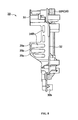
- FIG. 3 is an enlarged view in the vicinity of the radiator 60 shown in FIG. 2 .
- the alternator 91 includes a flywheel magnet rotor 91a and a magnet stator 91b.
- the flywheel magnet rotor 91a is fixed to a tip end of the crank shaft 83 with a nut 83a.
- the magnet stator 91b is fixed to the crank case 90B.
- the fan 92 is fixed to a back surface of the flywheel magnet rotor 91a with a bolt 92a.
- the fan 92 and the flywheel magnet rotor 91a rotate along with rotation of the crank shaft 83.
- a rotating shaft of the fan 92 is disposed coaxially with the crank shaft 83.
- the fan 92 has a disc-shaped rotor plate 92b, and a plurality of wings 92c.
- the wings 92c are provided on a surface of the rotor plate 92b on the radiator 60 side, along the rotating direction of the rotor plate 92b.
- the fan case 30 is connected to the crank case 90B.
- An opening 31 that faces the radiator 60 is formed in the fan case 30.
- a diameter L1 of the opening 31 is substantially the same as the outer diameter L2 of the fan 92.
- the fan case 30 has a cylinder section 33 and an edge section 32.
- the cylinder section 33 is disposed on the outside of the rotating direction of the fan 92.
- the edge section 32 is contiguous with the cylinder section 33, and surrounds an outer edge of the opening 31.
- the radiator 60 includes a plate-shaped radiator core 61, an upper tank 64 (refer to FIG. 4 ) disposed on the upper side of the radiator core 61, and a lower tank 65 (refer to FIG. 4 ) disposed on the lower side of the radiator core 61.
- a suction pipe 62 is connected to the upper tank 64.
- a water discharge pipe 63 is connected to the lower tank 65.
- a closure section 50 more specifically, a front side closure section 50F, a rear side closure section 50R, an upper side closure section 50U, and a lower side closure section 50D are attached with adhesive to the edge section 32 of the fan case 30 (refer to FIG. 5 ).
- the front side closure section 50F and the rear side closure section 50R attached with adhesive to the edge section 32 of the fan case 30 are tightly fitted to an inside surface 61a of the radiator core 61. More specifically, the front side closure section 50F and the rear side closure section 50R are tightly fitted to a front end section and a rear end section of the inside surface 61a, respectively.
- the outside air F that has been taken in is discharged to the outside of the fan 92 in the radial direction, via a discharge port 34 (refer to FIG. 6 ) formed in the fan case 30.
- a protruding section 90a that extends from the crank case 90B toward the fan 92 is disposed on the inner side of the cylinder section 33 of the fan case 30.
- the outside air F is directed to the outside of the fan 92 in the radial direction by the edge section 32 and the protruding section 90a.
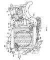
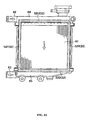
- FIG. 4 is a right side view of the radiator 60, the cylinder head 70, and the cylinder 80.
- the upper tank 64 and the lower tank 65 extend in the front-rear direction of the vehicle.
- the radiator core 61 connects the upper tank 64 and the lower tank 65.
- the radiator core 61 includes fins 61c and water flow pipes 61d.
- the fins 61c and the water flow pipes 61d are formed of metal.
- the water flow pipes 61d are disposed vertically, ie, in the vehicle up-down direction, at fixed intervals in the front-rear direction of the vehicle.
- Each fin 61c is disposed between the water flow pipes 61d, and produced by folding a sheet of metal a plurality of times.
- a water supply port 68a for supplying cooling water is formed in a rear end section of the upper tank 64.
- the water supply port 68a is closed by a cap 68b.
- a water discharge port 68c for discharging cooling water to the outside is formed in a rear section of the lower tank 65.
- the water discharge port 68c is closed by a lid 68d.
- the water discharge pipe 63 connected to the lower tank 65 and the cooling water pump 74 disposed in the cylinder head 70 are connected via a cooling water pipe 66c. That is, the cooling water cooled by the radiator 60 is introduced to the cooling water pump 74.
- the cooling water pump 74 and the cylinder 80 are connected via a cooling water pipe 66b.
- the cooling water fed by the cooling water pump 74 is introduced to a water jacket (not shown in the figures) inside the cylinder 80.
- a thermostat 67 disposed on a right sidewall of the cylinder 80, and the upper tank 64 of the radiator 60 are connected via a cooling water pipe 66a.
- the cooling water heated by the cylinder 80 is fed to the upper tank 64.
- the radiator 60 has protrusions 69a to 69c for attaching the radiator 60 to the fan case 30 using bolts.
- FIG. 5 is a side view of the outside of the fan case 30.
- the front side closure section 50F and the rear side closure section 50R are attached with adhesive to the fan case 30 along the up-down direction of the vehicle.
- the front closure section 50F is provided corresponding to the front-end section of the radiator 60.
- the rear side closure section 50R is provided corresponding to the rear end section of the radiator 60.
- the upper side closure section 50U and the lower side closure section 50D are attached with adhesive to the fan case 30 along the front-rear direction of the vehicle.
- the upper side closure section 50U is provided to correspond with the upper tank 64 of the radiator 60.
- the lower side closure section 50D is provided to correspond with the lower tank 65 of the radiator 60.
- the thickness of the radiator core 61 in the vehicle width direction is smaller than the thickness of the upper tank 64 and the lower tank 65 in the vehicle width direction.
- the thickness of the closure section 50 is set to correspond to the size of the gap. Accordingly, the thickness of the front side closure section 50F and the rear side closure section 50R may be larger than the thickness of the upper side closure section 50U and the lower side closure section 50D.
- the fan case 30 includes boss sections 30a to 30c that are provided to correspond with the protrusions 69a to 69c of the radiator 60.
- FIG. 6 is a side view of the inside of the fan case 30.
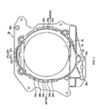
- FIG. 7 is a front view of the fan case 30 and the radiator 60. Note that FIG. 7 shows a state where the radiator 60 has been removed from the fan case 30.
- FIG. 8 is a rear view of the fan case 30.
- a front side discharge port 34F, an upper side discharge port 34U, and a rear side discharge port 34R are formed in the cylinder section 33 of the fan case 30.
- the front side discharge port 34F is formed in a front section of the cylinder section 33.
- the front side discharge port 34F is provided with a plurality of rod-like sections 36a to 36e at fixed intervals apart in order to prevent foreign matter from entering.
- the upper side discharge port 34U is formed in an upper section of the cylinder section 33. As shown in FIG. 6 , the upper side discharge port 34U is provided with a plurality of rod-like sections 37a to 37c at fixed intervals apart.
- the rear side discharge port 34R is formed in a rear section of the cylinder section 33. As shown in FIG. 6 and FIG. 8 , the rear side discharge port 34R is provided with a plurality of rod-like sections 35a to 35c at fixed intervals apart.
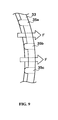
- FIG. 9 is an enlarged plan view of the rod-like sections 35a to 35c provided in the rear side discharge port 34R.
- the rod-like sections 35a to 35c are formed to have a convex shape that extends in the direction of discharge of outside air F. As a result, turbulence of the flow of the discharged outside air F is inhibited. Accordingly, flow noise caused by the turbulence of the flow of the discharged outside air F is reduced.
- the motorcycle 10 includes the radiator 60 having the plate-shaped radiator core 61 that contacts the outside air F, the fan 92 that is disposed to face the radiator core 61 and takes or draws in the outside air F, and the fan case 30 that covers the fan 92 and is disposed at a predetermined distance away from the radiator 60.
- the opening 31 is formed in the fan case 30 such that it faces the radiator core 61.
- the fan case 30 includes the edge section 32 that surrounds the outer edge of the opening 31, and the closure section 50 that closes the gap between the edge section 32 and the radiator 60.
- the outside air F taken in by the fan 92 hardly passes through the gap between the edge section of the fan case 30 and the radiator 60.
- the outside air F taken in by the fan 92 is more reliably fed to the radiator core 61.
- the cooling ability of the radiator unit can be improved.
- the closure section 50 is formed by urethane. Accordingly, even if the closure section 50 is tightly fitted to the radiator core 61, damage to the radiator core 61 (more specifically, the fins 61c), which has a relatively low strength, can be inhibited.
- the closure section 50 is attached with adhesive to the edge section 32 of the fan case 30.
- the temperature of the radiator 60 becomes high because the cooling water at a high temperature is introduced from the cylinder 80. Accordingly, when the closure section 50 is attached using adhesive to the radiator 60, there is a possibility that the closure section 50 will detach from the radiator 60.
- the closure section 50 is attached with adhesive to the edge section 32 of the fan case 30 as in the embodiment, the possibility that the closure section 50 will detach from the edge section 32 of the fan case 30 is reduced.
- an outside surface 61b of the radiator core 61 is disposed toward the outside in the vehicle width direction. That is, the radiator 60 is disposed at a location where running wind hardly hits the radiator 60.
- the cooling ability of the radiator unit can be significantly increased.
- the diameter L1 of the opening 31 formed in the fan case 30 is substantially the same as the outer diameter L2 of the fan 92. Accordingly, while the outside air F discharged to the outside by the fan 92 is inhibited from leaking to the radiator 60 side, the amount of the outside air F introduced to the inside by the fan 92 can be increased. Thus, the cooling ability of the radiator unit can be improved.
- a closure section 51 (a front side closure section 51F and a rear side closure section 51R) extends from the edge section 32 toward the outside in the vehicle width direction. More specifically, the front side closure section 51F extends from the edge section 32 to the front end of the radiator core 61. The rear side closure section 51R extends from the edge section 32 to the rear end of the radiator core 61.
- closure section 50 is attached with adhesive to the edge section 32 of the fan case 30 in the above-described embodiment
- a closure section 52 may be attached to the radiator 60 with adhesive as shown in FIG. 11 .
- the closure section 52 is attached with adhesive to an outer edge section of the inside surface of the radiator 60.
- closure section 50 is formed of urethane in the above-described embodiment, it may be formed of other materials.
- an elastic member made of polystyrene foam (a foaming material) or rubber may be used as the material of the closure section 50.
- the closure section 50 is provided in the radiator unit including the radiator 60 and the fan 92.
- the structure in which the closure section 50 is provided may be applied to another heat exchanger, such as an oil cooler.
- the radiator 60 is provided in a side section of the vehicle, more specifically, on the right side of the vehicle.
- the radiator 60 may be provided, for example, in a rear section of the vehicle. That is, if the closure section 50 according to the above-described embodiment is provided in a structure where the radiator unit is disposed at a location where running wind hardly hits it, the cooling ability of the radiator unit can be improved.
- radiator unit is disposed at a location where running wind directly hits it, for example, in a front section of the vehicle, it is readily apparent that the cooling ability of the radiator unit can be improved by providing the closure section 50 according to the above-described embodiment.
Landscapes
- Engineering & Computer Science (AREA)
- Chemical & Material Sciences (AREA)
- Combustion & Propulsion (AREA)
- Transportation (AREA)
- Mechanical Engineering (AREA)
- Cooling, Air Intake And Gas Exhaust, And Fuel Tank Arrangements In Propulsion Units (AREA)
- Automatic Cycles, And Cycles In General (AREA)
Abstract
Description
- The present invention relates to a straddle-type vehicle that includes a heat exchanger having a plate-shaped core that contacts outside air, a fan that is disposed to face the core and takes or draws in outside air, and a fan case that covers the fan and is disposed at a predetermined distance away from the heat exchanger.
- In straddle-type vehicles such as motorcycles having a water-cooled engine, a heat exchanger is typically provided in order to lower the temperature of engine coolant (water). Known heat exchangers have plate-shaped cores arranged to be contacted with outside air. Outside air passing through the core removes the heat of the coolant inside.
- In straddle-type vehicles that include a heat exchanger like that described above, a method that is widely used takes in outside air using a fan disposed to face the core of the heat exchanger. Such an arrangement is disclosed in, for example,
JP-A-2005-119501 - The fan is covered by a fan case. For the ease of installation, the fan case is fixed at a predetermined distance or clearance from the heat exchanger.
- However, there is room for more improvement in the above-described known method that will improve the cooling ability of the heat exchanger unit.
- Particularly, when the heat exchanger unit is positioned in a side of the vehicle, the running or traveling wind is less likely to hit the core of the heat exchanger, as compared to when the heat exchanger unit is positioned at the front of the vehicle. Therefore, it is desirable to improve the cooling ability of the heat exchanger unit, which can be achieved by using a fan to more reliably feed outside air taken in by the fan to the core of the heat exchanger.
- The invention has been devised in light of the above-described circumstances. It is an object of an embodiment of the invention to provide a straddle-type vehicle with a heat exchanger unit with an improved cooling ability.
- According to an aspect of the present invention there is provided a straddle-type vehicle comprising:
- a heat exchanger including a plate-shaped core adapted to contact outside air;
- a fan arranged to face the core and draw in outside air; and
- a fan case arranged to cover the fan and being disposed at a predetermined distance away from the heat exchanger, wherein the fan case defines an opening that faces the core, and includes an edge section that surrounds an outer edge of the opening,
- wherein one of the fan case and the heat exchanger includes a closure section that closes a gap between the edge section and the heat exchanger.
- The closure section may be formed of an elastic member.
- The closure section may be adhesively attached to the edge section.
- The core may include a surface facing the fan and an opposing surface. The opposing surface may be positioned to face in a direction other than a forward direction of the vehicle.
- The opposing surface may be disposed to face toward an outside in a vehicle width direction.
- A diameter of the opening may be substantially the same as the outer diameter of the fan.
- According to a further aspect of the present invention there is provided a vehicle heat exchanger assembly comprising:
- a heat exchanger including a plate-shaped core adapted to contact outside air;
- a fan arranged to face the core and draw in outside air; and
- a fan case arranged to cover the fan and being disposed at a predetermined distance away from the heat exchanger, wherein the fan case defines an opening that faces the core, and includes an edge section that surrounds an outer edge of the opening,
- wherein one of the fan case and the heat exchanger includes a closure section that closes a gap between the edge section and the heat exchanger.
- A further aspect of the invention provides a heat exchanger including a plate-shaped core that contacts outside air; a fan that is disposed to face the core and takes in outside air; and a fan case that covers the fan. The fan case is fixed at a predetermined distance from the heat exchanger. An opening that faces the core is formed in the fan case. The fan case includes an edge section that surrounds an outer edge of the opening. The fan case or the heat exchanger includes a closure section that closes the gap between the edge section and the heat exchanger.
- According to this aspect, the outside air taken in by the fan hardly passes through the gap between the edge section of the fan case and the heat exchanger. In other words, the outside air taken in by the fan can be more reliably fed to the core of the heat exchanger. Thus, the cooling ability of the heat exchanger unit is improved.
- The closure section may be formed of an elastic material, for example, urethane.
- The closure section may be adhesively attached to the edge section.
- The core may have an outside surface that is a surface on an opposite side of a surface that faces the fan. The outside surface may be positioned to face in a direction other than the forward direction of the vehicle.
- The outside surface may be disposed to face toward an outside in a vehicle width direction.
- A diameter of the opening may be substantially the same as the outer diameter of the fan.
- According to the invention, the outside air taken in by the fan can be more reliably introduced to the core of the heat exchanger. Thus, it is possible to provide a heat exchanger unit with an improved cooling ability in a saddle type vehicle.
- These and other aspects of the present invention will now be described, by way of example only, with reference to the accompanying drawings, in which:
-
FIG. 1 is a left side view of a motorcycle according to an embodiment of the invention; -
FIG. 2 is a schematic cross sectional view of a swing type engine unit along the line A-A inFIG. 1 ; -
FIG. 3 is an enlarged view of the vicinity of a radiator shown inFIG. 2 ; -
FIG. 4 is a right side view of the radiator, a cylinder head, and a cylinder according to the embodiment of the invention; -
FIG. 5 is a side view of the outside of a fan case according to the embodiment of the invention; -
FIG. 6 is a side view of the inside of the fan case according to the embodiment of the invention; -
FIG. 7 is a front view of the fan case and the radiator according to the embodiment of the invention; -
FIG. 8 is a rear view of the fan case according to the embodiment of the invention; -
FIG. 9 is a partially enlarged view ofFIG. 6 ; -
FIG. 10 is a view showing the structure of a closure section according to another embodiment; and -
FIG. 11 is a view showing the structure of a closure section according to another embodiment. - Hereinafter, the structure of a straddle-type vehicle according to an embodiment of the invention will be described with reference to the appended drawings. More specifically, the (1) Overall schematic structure, (2) Structure of the swing type engine unit, (3) Operations and effects, and (4) Other embodiments will be described.
- Note that, in the following drawings, structural members that are the same or similar are denoted with the same or similar reference numerals. Also note that the figures are schematic, and thus the reader should be aware that the relative scale of dimensions and the like might be different to the real object.
- However, specific dimensions and the like may be determined based on reference to the following description. In addition, it will be readily apparent that the various figures include sections in which the relationship and scale of respective dimensions etc. are different.
- First, the overall schematic structure of the straddle-type vehicle according to the embodiment will be described.
FIG. 1 is a left side view of amotorcycle 10 according to the embodiment. - As shown in
FIG. 1 , themotorcycle 10 is an underbone motorcycle in which a body frame (not shown in the figures) is disposed at a lower location than that of a normal motorcycle. - The
motorcycle 10 includes afront wheel 21 and arear wheel 22, and uses a swingtype engine unit 40 to drive therear wheel 22. The swingtype engine unit 40 is provided below a seat 20 on which a rider sits, and extends in the front-rear direction of the vehicle. - The swing
type engine unit 40 includes acylinder head 70, acylinder 80 connected to thecylinder head 70, a crankcase 90B (refer toFIG. 2 ) connected to thecylinder 80, and atransmission case 90A. - The swing
type engine unit 40 is provided with aradiator 60 on the right side of the vehicle. In this embodiment, a water-cooled, single cylinder, four-stroke engine includes thecylinder head 70, thecylinder 80, and theradiator 60. - The
transmission case 90A houses a transmission unit (not shown in the figures). The transmission unit transmits power generated by the engine including thecylinder head 70 and thecylinder 80 to therear wheel 22. - An upper section of the
transmission case 90A is provided with acushion unit 23 that is fixed to the body frame. The body frame rotatably supports the lower side of a front section of thetransmission case 90A. A rear section of thetransmission case 90A can swing in the up-down direction of the vehicle. - Next, the structure of the swing
type engine unit 40 will be described with reference toFIG. 2 to FIG. 9 . More specifically, the (2.1) Overall schematic structure of the swing type engine unit, (2.2) Structure of the vicinity of the radiator, (2.3) Detailed structures of the fan case, the radiator, and the closure section will be described. -
FIG. 2 is a schematic cross sectional view of the swingtype engine unit 40 along the line A-A inFIG. 1 . Note that hatching is omitted inFIG. 2 . - The
cylinder 80 is provided on a vehicle centerline that divides the vehicle width into two substantially equal halves. Thecylinder 80 includes apiston 81 and a connectingrod 82. - The
piston 81 is inserted into thecylinder 80. The connectingrod 82 transmits the power of thepiston 81 to a crankshaft 83. - The crank
case 90B houses thecrank shaft 83 disposed in the vehicle width direction. - The
transmission case 90A houses a starter clutch 93a, adrive pulley 93b, adrive belt 94, a drivenpulley 95a, adrive shaft 95c, a gearspeed reduction mechanism 95d, etc. - The starter clutch 93a is connected to the
crank shaft 83 on the left side of the vehicle centerline. The starter clutch 93a is housed in a starterclutch housing 93c. - The
drive pulley 93b is connected to thecrank shaft 83 on the left side of the starter clutch 93a. The drivenpulley 95a is connected to thedrive shaft 95c. - The
drive belt 94 is wound around thedrive pulley 93b and the drivenpulley 95a. Thedrive pulley 93b, thedrive belt 94 and the drivenpulley 95a form a V-belt type automatic transmission mechanism. - A
rear axle 25 is provided to the rear of thedrive shaft 95c. The driving force of thecrank shaft 83 is transmitted to thedrive shaft 95c via thedrive pulley 93b, thedrive belt 94, and the drivenpulley 95a, and then transmitted from thedrive shaft 95c to therear axle 25 via the gearspeed reduction mechanism 95d. - The
cylinder head 70 includes acam shaft 73 that extends in the vehicle width direction. Acam sprocket 72 is fixed to one end of thecam shaft 73. A cam chain 71 is wound around acrank sprocket 93d fixed to thecrank shaft 83, and thecam sprocket 72. - A cooling
water pump 74 and abreather device 75 are provided on the left side of thecylinder head 70. The coolingwater pump 74 feeds cooling water to cooling water passages provided in theradiator 60, thecylinder 80 etc. - Blow-by gas in the
crank case 90B flows through acam chain chamber 76 and flows into thebreather device 75. Thebreather device 75 separates the blow-by gas into engine oil and air. - An
alternator 91 is connected to thecrank shaft 83 on the right side of the vehicle centerline. Afan 92 is fastened to thealternator 91. - The
centrifugal fan 92 takes or draws in outside air F and subsequently discharges this air F that to the outside. A section of thefan 92 is covered by afan case 30 that is fixed to the crankcase 90B. In this embodiment, thefan case 30 is formed of an aluminum alloy. - The
radiator 60 is provided on the right side of thefan 92, along the front-rear direction of the vehicle. Theradiator 60 and thefan 92 form a radiator unit. - Rotation of the
fan 92 causes the outside air F to be introduced via aradiator cover 96 and theradiator 60. Theradiator 60 is filled with cooling water that cools thecylinder 80, and thecylinder head 70 etc. The outside air F introduced by thefan 92 cools the cooling water in theradiator 60. - The
radiator cover 96 is made of plastic, and disposed on the right side of theradiator 60. Theradiator cover 96 is fixed to thefan case 30, and covers the right side of theradiator 60. - Next, the structure in the vicinity of the
radiator 60 shown inFIG. 2 , and more specifically, the structures of thealternator 91, thefan 92, and theradiator 60 will be described.FIG. 3 is an enlarged view in the vicinity of theradiator 60 shown inFIG. 2 . - The
alternator 91 includes aflywheel magnet rotor 91a and amagnet stator 91b. Theflywheel magnet rotor 91a is fixed to a tip end of thecrank shaft 83 with anut 83a. Themagnet stator 91b is fixed to the crankcase 90B. - The
fan 92 is fixed to a back surface of theflywheel magnet rotor 91a with abolt 92a. Thefan 92 and theflywheel magnet rotor 91a rotate along with rotation of thecrank shaft 83. - To be more specific, a rotating shaft of the
fan 92 is disposed coaxially with thecrank shaft 83. Thefan 92 has a disc-shapedrotor plate 92b, and a plurality ofwings 92c. Thewings 92c are provided on a surface of therotor plate 92b on theradiator 60 side, along the rotating direction of therotor plate 92b. - The
fan case 30 is connected to the crankcase 90B. Anopening 31 that faces theradiator 60 is formed in thefan case 30. In this embodiment, a diameter L1 of theopening 31 is substantially the same as the outer diameter L2 of thefan 92. - The
fan case 30 has acylinder section 33 and anedge section 32. Thecylinder section 33 is disposed on the outside of the rotating direction of thefan 92. Theedge section 32 is contiguous with thecylinder section 33, and surrounds an outer edge of theopening 31. - The
radiator 60 includes a plate-shapedradiator core 61, an upper tank 64 (refer toFIG. 4 ) disposed on the upper side of theradiator core 61, and a lower tank 65 (refer toFIG. 4 ) disposed on the lower side of theradiator core 61. Asuction pipe 62 is connected to theupper tank 64. Awater discharge pipe 63 is connected to thelower tank 65. - A
closure section 50, more specifically, a frontside closure section 50F, a rearside closure section 50R, an upperside closure section 50U, and a lowerside closure section 50D are attached with adhesive to theedge section 32 of the fan case 30 (refer toFIG. 5 ). - In
FIG. 3 , the frontside closure section 50F and the rearside closure section 50R attached with adhesive to theedge section 32 of thefan case 30 are tightly fitted to aninside surface 61a of theradiator core 61. More specifically, the frontside closure section 50F and the rearside closure section 50R are tightly fitted to a front end section and a rear end section of theinside surface 61a, respectively. - In this manner, a gap between the
edge section 32 of thefan case 30 and theradiator 60 is closed by theclosure section 50. - When the
fan 92 rotates along with thecrank shaft 83, the outside air F on the outside of theradiator 60 in the vehicle width direction passes through theradiator core 61 and theopening 31 and is taken into thefan case 30. - The outside air F that has been taken in is discharged to the outside of the
fan 92 in the radial direction, via a discharge port 34 (refer toFIG. 6 ) formed in thefan case 30. Note that a protrudingsection 90a that extends from thecrank case 90B toward thefan 92 is disposed on the inner side of thecylinder section 33 of thefan case 30. The outside air F is directed to the outside of thefan 92 in the radial direction by theedge section 32 and the protrudingsection 90a. - Next, the detailed structures of the
radiator 60, thefan case 30, and theclosure section 50 will be described with reference toFIG. 4 to FIG. 9 . -
FIG. 4 is a right side view of theradiator 60, thecylinder head 70, and thecylinder 80. - The
upper tank 64 and thelower tank 65 extend in the front-rear direction of the vehicle. Theradiator core 61 connects theupper tank 64 and thelower tank 65. - The
radiator core 61 includesfins 61c andwater flow pipes 61d. Thefins 61c and thewater flow pipes 61d are formed of metal. - The
water flow pipes 61d are disposed vertically, ie, in the vehicle up-down direction, at fixed intervals in the front-rear direction of the vehicle. Eachfin 61c is disposed between thewater flow pipes 61d, and produced by folding a sheet of metal a plurality of times. - A
water supply port 68a for supplying cooling water is formed in a rear end section of theupper tank 64. Thewater supply port 68a is closed by acap 68b. - A
water discharge port 68c for discharging cooling water to the outside is formed in a rear section of thelower tank 65. Thewater discharge port 68c is closed by alid 68d. - The
water discharge pipe 63 connected to thelower tank 65 and the coolingwater pump 74 disposed in thecylinder head 70 are connected via a coolingwater pipe 66c. That is, the cooling water cooled by theradiator 60 is introduced to the coolingwater pump 74. - The cooling
water pump 74 and thecylinder 80 are connected via a coolingwater pipe 66b. Thus, the cooling water fed by the coolingwater pump 74 is introduced to a water jacket (not shown in the figures) inside thecylinder 80. - A
thermostat 67 disposed on a right sidewall of thecylinder 80, and theupper tank 64 of theradiator 60 are connected via a coolingwater pipe 66a. The cooling water heated by thecylinder 80 is fed to theupper tank 64. - Note that the
radiator 60 hasprotrusions 69a to 69c for attaching theradiator 60 to thefan case 30 using bolts. - Next, the detailed structure of the
closure section 50 will be described.FIG. 5 is a side view of the outside of thefan case 30. - As shown in
FIG. 5 , the frontside closure section 50F and the rearside closure section 50R are attached with adhesive to thefan case 30 along the up-down direction of the vehicle. Thefront closure section 50F is provided corresponding to the front-end section of theradiator 60. The rearside closure section 50R is provided corresponding to the rear end section of theradiator 60. - The upper
side closure section 50U and the lowerside closure section 50D are attached with adhesive to thefan case 30 along the front-rear direction of the vehicle. The upperside closure section 50U is provided to correspond with theupper tank 64 of theradiator 60. The lowerside closure section 50D is provided to correspond with thelower tank 65 of theradiator 60. - Note that, in the
radiator 60, the thickness of theradiator core 61 in the vehicle width direction is smaller than the thickness of theupper tank 64 and thelower tank 65 in the vehicle width direction. In addition, in order to reliably close the gap between theradiator 60 and thefan case 30, it is desirable that the thickness of theclosure section 50 is set to correspond to the size of the gap. Accordingly, the thickness of the frontside closure section 50F and the rearside closure section 50R may be larger than the thickness of the upperside closure section 50U and the lowerside closure section 50D. - Further, the
fan case 30 includesboss sections 30a to 30c that are provided to correspond with theprotrusions 69a to 69c of theradiator 60. - Next, the detailed structure of the
fan case 30 will be described.FIG. 6 is a side view of the inside of thefan case 30.FIG. 7 is a front view of thefan case 30 and theradiator 60. Note thatFIG. 7 shows a state where theradiator 60 has been removed from thefan case 30.FIG. 8 is a rear view of thefan case 30. - A front
side discharge port 34F, an upper side discharge port 34U, and a rearside discharge port 34R are formed in thecylinder section 33 of thefan case 30. - The front
side discharge port 34F is formed in a front section of thecylinder section 33. The frontside discharge port 34F is provided with a plurality of rod-like sections 36a to 36e at fixed intervals apart in order to prevent foreign matter from entering. - The upper side discharge port 34U is formed in an upper section of the
cylinder section 33. As shown inFIG. 6 , the upper side discharge port 34U is provided with a plurality of rod-like sections 37a to 37c at fixed intervals apart. - The rear
side discharge port 34R is formed in a rear section of thecylinder section 33. As shown inFIG. 6 andFIG. 8 , the rearside discharge port 34R is provided with a plurality of rod-like sections 35a to 35c at fixed intervals apart. -
FIG. 9 is an enlarged plan view of the rod-like sections 35a to 35c provided in the rearside discharge port 34R. - As shown in
FIG. 9 , the rod-like sections 35a to 35c are formed to have a convex shape that extends in the direction of discharge of outside air F. As a result, turbulence of the flow of the discharged outside air F is inhibited. Accordingly, flow noise caused by the turbulence of the flow of the discharged outside air F is reduced. - As described above, according to the embodiment, the
motorcycle 10 includes theradiator 60 having the plate-shapedradiator core 61 that contacts the outside air F, thefan 92 that is disposed to face theradiator core 61 and takes or draws in the outside air F, and thefan case 30 that covers thefan 92 and is disposed at a predetermined distance away from theradiator 60. - The
opening 31 is formed in thefan case 30 such that it faces theradiator core 61. Thefan case 30 includes theedge section 32 that surrounds the outer edge of theopening 31, and theclosure section 50 that closes the gap between theedge section 32 and theradiator 60. - Accordingly, the outside air F taken in by the
fan 92 hardly passes through the gap between the edge section of thefan case 30 and theradiator 60. In other words, the outside air F taken in by thefan 92 is more reliably fed to theradiator core 61. As a result, the cooling ability of the radiator unit can be improved. - Further, according to the embodiment, the
closure section 50 is formed by urethane. Accordingly, even if theclosure section 50 is tightly fitted to theradiator core 61, damage to the radiator core 61 (more specifically, thefins 61c), which has a relatively low strength, can be inhibited. - According to the embodiment, the
closure section 50 is attached with adhesive to theedge section 32 of thefan case 30. The temperature of theradiator 60 becomes high because the cooling water at a high temperature is introduced from thecylinder 80. Accordingly, when theclosure section 50 is attached using adhesive to theradiator 60, there is a possibility that theclosure section 50 will detach from theradiator 60. On the other hand, when theclosure section 50 is attached with adhesive to theedge section 32 of thefan case 30 as in the embodiment, the possibility that theclosure section 50 will detach from theedge section 32 of thefan case 30 is reduced. - In addition, according to the embodiment, an
outside surface 61b of theradiator core 61 is disposed toward the outside in the vehicle width direction. That is, theradiator 60 is disposed at a location where running wind hardly hits theradiator 60. As a result of providing the above-describedclosure section 50 in a structure where theradiator 60 is disposed at the location where running wind hardly hits it, the cooling ability of the radiator unit can be significantly increased. - According to the embodiment, the diameter L1 of the
opening 31 formed in thefan case 30 is substantially the same as the outer diameter L2 of thefan 92. Accordingly, while the outside air F discharged to the outside by thefan 92 is inhibited from leaking to theradiator 60 side, the amount of the outside air F introduced to the inside by thefan 92 can be increased. Thus, the cooling ability of the radiator unit can be improved. - Hereinabove, one embodiment of the invention is described. However, it is to be understood that the invention is not limited by the description and the drawings that constitute one section of the disclosure. From the disclosure, it will be apparent to those skilled in the art that the invention permits various alternative embodiments, examples and operation technologies.
- Although the
closure section 50 is attached using adhesive to theedge section 32 of thefan case 30 in the above-described embodiment, theclosure section 50 and theedge section 32 may be provided as a unit. In the example shown inFIG. 10 , a closure section 51 (a frontside closure section 51F and a rearside closure section 51R) extends from theedge section 32 toward the outside in the vehicle width direction. More specifically, the frontside closure section 51F extends from theedge section 32 to the front end of theradiator core 61. The rearside closure section 51R extends from theedge section 32 to the rear end of theradiator core 61. - Moreover, although the
closure section 50 is attached with adhesive to theedge section 32 of thefan case 30 in the above-described embodiment, aclosure section 52 may be attached to theradiator 60 with adhesive as shown inFIG. 11 . InFIG. 11 , theclosure section 52 is attached with adhesive to an outer edge section of the inside surface of theradiator 60. - Although the
closure section 50 is formed of urethane in the above-described embodiment, it may be formed of other materials. For example, as the material of theclosure section 50, an elastic member made of polystyrene foam (a foaming material) or rubber may be used. - In the above-described embodiment, a structure is described in which the
closure section 50 is provided in the radiator unit including theradiator 60 and thefan 92. However, the structure in which theclosure section 50 is provided may be applied to another heat exchanger, such as an oil cooler. - Moreover, in the above-described embodiment, the
radiator 60 is provided in a side section of the vehicle, more specifically, on the right side of the vehicle. However, instead of the side section of the vehicle, theradiator 60 may be provided, for example, in a rear section of the vehicle. That is, if theclosure section 50 according to the above-described embodiment is provided in a structure where the radiator unit is disposed at a location where running wind hardly hits it, the cooling ability of the radiator unit can be improved. - Note that, also in a structure where the radiator unit is disposed at a location where running wind directly hits it, for example, in a front section of the vehicle, it is readily apparent that the cooling ability of the radiator unit can be improved by providing the
closure section 50 according to the above-described embodiment. - As will be readily apparent, the invention includes various embodiments not described here. Accordingly, the invention is defined only by the specific features of the invention set forth in the claims that are reasonable given the above description.
- 10 ... Motorcycle, 20 ... Seat, 21 ... Front wheel, 22 ... Rear wheel, 23 ... Cushion unit, 25 ... Rear wheel, 30 ... Fan case, 30a to 30c ... Boss sections, 31 ... Opening, 32 ... Edge section, 33 ... Cylinder section, 34... Discharge port, 34F ... Front side discharge port, 34R ... Rear side discharge port, 34U ... Upper side discharge port, 35R ... Rear side discharge port, 35a to 35c, 36a to 36e, 37a to 37c ... Rod-like sections, 40 ... Swing type engine unit, 50, 51, 52 ... Closure sections, 50D ... Lower side closure section, 50F, 51F ... Front side closure sections, 50R, 51R ... Rear side closure sections, 50U ... Upper side closure section, 60 ... Radiator, 61 ... Radiator core, 61a ... Inside surface, 61b ... Outside surface, 61c ... Fins, 61d ... Water flow pipes, 62 ... Suction pipe, 63 ... water discharge pipe, 64 ... Upper tank, 65 ... Lower tank, 66a to 66c ... Cooling water pipe, 67 ... Thermostat, 68a ... Water supply port, 68b ... Cap, 68c ... Water discharge port, 68d ... Lid, 69a to 69c ... Protrusions, 70 ... Cylinder head, 71 ... Cam chain, 72 ... Cam sprocket, 73 ... Cam shaft, 74 ... Cooling water pump, 75 ... Breather device, 76 ... Cam chain chamber, 80 ... Cylinder, 81 ... Piston, 82 ... Connecting rod, 83 ... Crank shaft, 83a ... Nut, 90A ... Transmission case, 90B ... Crank case, 90a ... Protruding section, 91 ... Alternator, 91a ... Flywheel magnet rotor, 91b ... Magnet stator, 92 ... Fan, 92a ... Bolt, 92b ... Rotor plate, 92c ... Radiator, 92c ... Wings, 93a ... Starter clutch, 93b ... Drive pulley, 93c ... Starter clutch housing, 93d ... Crank sprocket, 94 ... Drive belt, 95a ... Driven pulley, 95c ... Drive shaft, 95d ... Gear speed reduction mechanism, 96 ... Radiator cover
Claims (7)
- A straddle-type vehicle (10) comprising:a heat exchanger (60) including a core (61) adapted to contact outside air (F);a fan (92) arranged to face the core (61) and draw in outside air (F); anda fan case (30) arranged to cover the fan (92) and being disposed at a predetermined distance away from the heat exchanger (60), wherein the fan case (30) defines an opening (31) that faces the core (61), and includes an edge section (32) that surrounds an outer edge of the opening (31),wherein one of the fan case (30) and the heat exchanger (60) includes a closure section (50) that closes a gap between the edge section (32) and the heat exchanger (60).
- The straddle-type vehicle (10) according to claim 1,
wherein the closure section (50) is formed of an elastic member. - The straddle-type vehicle (10) according to claim 1 or 2, wherein the closure section (50) is adhesively attached to the edge section (32).
- The straddle-type vehicle (10) according to claim 1, 2 or 3, wherein the core (61) includes a surface facing the fan and an opposing surface, wherein the opposing surface is positioned to face in a direction other than a forward direction of the vehicle (10).
- The straddle-type vehicle (10) according to claim 4, where the opposing surface is disposed to face toward an outside in a vehicle width direction.
- The straddle-type vehicle (10) according to any preceding claim, where a diameter (L1) of the opening (31) is substantially the same as the outer diameter (L2) of the fan (92).
- A vehicle heat exchanger assembly comprising:a heat exchanger (60) including a core (61) adapted to contact outside air (F);a fan (92) arranged to face the core (61) and draw in outside air (F); anda fan case (30) arranged to cover the fan (92) and being disposed at a predetermined distance away from the heat exchanger (60), wherein the fan case (30) defines an opening (31) that faces the core (61), and includes an edge section (32) that surrounds an outer edge of the opening (31),wherein one of the fan case (30) and the heat exchanger (60) includes a closure section (50) that closes a gap between the edge section (32) and the heat exchanger (60).
Applications Claiming Priority (1)
| Application Number | Priority Date | Filing Date | Title |
|---|---|---|---|
| JP2007202181A JP2009035177A (en) | 2007-08-02 | 2007-08-02 | Saddle riding vehicle |
Publications (2)
| Publication Number | Publication Date |
|---|---|
| EP2022658A1 true EP2022658A1 (en) | 2009-02-11 |
| EP2022658B1 EP2022658B1 (en) | 2012-02-29 |
Family
ID=39857758
Family Applications (1)
| Application Number | Title | Priority Date | Filing Date |
|---|---|---|---|
| EP08252530A Active EP2022658B1 (en) | 2007-08-02 | 2008-07-24 | Straddle-type vehicle |
Country Status (7)
| Country | Link |
|---|---|
| EP (1) | EP2022658B1 (en) |
| JP (1) | JP2009035177A (en) |
| CN (1) | CN101357655B (en) |
| AT (1) | ATE547276T1 (en) |
| BR (1) | BRPI0803704B1 (en) |
| ES (1) | ES2382015T3 (en) |
| TW (1) | TWI333024B (en) |
Cited By (5)
| Publication number | Priority date | Publication date | Assignee | Title |
|---|---|---|---|---|
| EP2474723A4 (en) * | 2009-09-03 | 2017-01-25 | Honda Motor Co., Ltd. | Cooling structure for radiator for water-cooled power unit |
| ITUB20155584A1 (en) * | 2015-11-13 | 2017-05-13 | Piaggio & C Spa | Engine cooling system of a motor vehicle |
| CN107791826A (en) * | 2016-09-05 | 2018-03-13 | 福特环球技术公司 | Shield and radiating subassembly for the radiating subassembly of vehicle |
| WO2018115132A1 (en) | 2016-12-22 | 2018-06-28 | Piaggio & C. S.P.A | Cooling system of the engine of a motorcycle |
| US11458832B2 (en) | 2016-11-04 | 2022-10-04 | Piaggio & C. S.P.A. | Motorcycle engine cooling system |
Families Citing this family (3)
| Publication number | Priority date | Publication date | Assignee | Title |
|---|---|---|---|---|
| CN102777539B (en) * | 2011-05-09 | 2014-12-10 | 光阳工业股份有限公司 | Vehicle power system |
| JP6276213B2 (en) * | 2015-03-26 | 2018-02-07 | 本田技研工業株式会社 | Saddle riding |
| CN108252789A (en) * | 2017-11-20 | 2018-07-06 | 观致汽车有限公司 | Vibration damping cooling fan mounting bracket and apply its cooling system, automobile |
Citations (5)
| Publication number | Priority date | Publication date | Assignee | Title |
|---|---|---|---|---|
| JPS6116130A (en) * | 1984-07-04 | 1986-01-24 | Nissan Motor Co Ltd | Structure of radiator mount |
| JPS61122030A (en) * | 1984-11-19 | 1986-06-10 | Honda Motor Co Ltd | Engine cooling device for motorcycle |
| US5046554A (en) * | 1990-02-22 | 1991-09-10 | Calsonic International, Inc. | Cooling module |
| US5566954A (en) * | 1993-11-08 | 1996-10-22 | Hahn Elastomer Corporation | Fan shroud attached air deflecting seal |
| JP2005119501A (en) | 2003-10-16 | 2005-05-12 | Yamaha Motor Co Ltd | Water cooling device for saddle riding type vehicle and saddle riding type vehicle |
-
2007
- 2007-08-02 JP JP2007202181A patent/JP2009035177A/en active Pending
-
2008
- 2008-06-05 TW TW097120973A patent/TWI333024B/en not_active IP Right Cessation
- 2008-07-24 EP EP08252530A patent/EP2022658B1/en active Active
- 2008-07-24 ES ES08252530T patent/ES2382015T3/en active Active
- 2008-07-24 AT AT08252530T patent/ATE547276T1/en active
- 2008-07-31 BR BRPI0803704-3A patent/BRPI0803704B1/en active IP Right Grant
- 2008-08-04 CN CN2008101342725A patent/CN101357655B/en active Active
Patent Citations (5)
| Publication number | Priority date | Publication date | Assignee | Title |
|---|---|---|---|---|
| JPS6116130A (en) * | 1984-07-04 | 1986-01-24 | Nissan Motor Co Ltd | Structure of radiator mount |
| JPS61122030A (en) * | 1984-11-19 | 1986-06-10 | Honda Motor Co Ltd | Engine cooling device for motorcycle |
| US5046554A (en) * | 1990-02-22 | 1991-09-10 | Calsonic International, Inc. | Cooling module |
| US5566954A (en) * | 1993-11-08 | 1996-10-22 | Hahn Elastomer Corporation | Fan shroud attached air deflecting seal |
| JP2005119501A (en) | 2003-10-16 | 2005-05-12 | Yamaha Motor Co Ltd | Water cooling device for saddle riding type vehicle and saddle riding type vehicle |
Cited By (10)
| Publication number | Priority date | Publication date | Assignee | Title |
|---|---|---|---|---|
| EP2474723A4 (en) * | 2009-09-03 | 2017-01-25 | Honda Motor Co., Ltd. | Cooling structure for radiator for water-cooled power unit |
| ITUB20155584A1 (en) * | 2015-11-13 | 2017-05-13 | Piaggio & C Spa | Engine cooling system of a motor vehicle |
| WO2017081633A1 (en) * | 2015-11-13 | 2017-05-18 | Piaggio & C. Spa | Motorcycle engine cooling apparatus |
| CN108290492A (en) * | 2015-11-13 | 2018-07-17 | 比亚乔及C.股份公司 | Motorcycle engine cools down equipment |
| US10294851B2 (en) | 2015-11-13 | 2019-05-21 | Piaggio & C. S.P.A. | Motorcycle engine cooling apparatus |
| TWI715666B (en) * | 2015-11-13 | 2021-01-11 | 義大利商比雅久股份有限公司 | Motorcycle engine cooling apparatus |
| CN107791826A (en) * | 2016-09-05 | 2018-03-13 | 福特环球技术公司 | Shield and radiating subassembly for the radiating subassembly of vehicle |
| CN107791826B (en) * | 2016-09-05 | 2022-05-24 | 福特环球技术公司 | Shield for heat dissipation assembly of vehicle and heat dissipation assembly |
| US11458832B2 (en) | 2016-11-04 | 2022-10-04 | Piaggio & C. S.P.A. | Motorcycle engine cooling system |
| WO2018115132A1 (en) | 2016-12-22 | 2018-06-28 | Piaggio & C. S.P.A | Cooling system of the engine of a motorcycle |
Also Published As
| Publication number | Publication date |
|---|---|
| TWI333024B (en) | 2010-11-11 |
| JP2009035177A (en) | 2009-02-19 |
| ES2382015T3 (en) | 2012-06-04 |
| TW200916648A (en) | 2009-04-16 |
| BRPI0803704B1 (en) | 2020-06-30 |
| CN101357655A (en) | 2009-02-04 |
| EP2022658B1 (en) | 2012-02-29 |
| ATE547276T1 (en) | 2012-03-15 |
| BRPI0803704A2 (en) | 2009-05-05 |
| CN101357655B (en) | 2012-11-14 |
Similar Documents
| Publication | Publication Date | Title |
|---|---|---|
| EP2022658B1 (en) | Straddle-type vehicle | |
| TWI449837B (en) | Power unit | |
| JP5504354B2 (en) | Straddle-type electric vehicle | |
| CN101239636B (en) | Straddle-type vehicle | |
| EP1958813B1 (en) | Vehicle | |
| EP1090791A2 (en) | Power unit for vehicle | |
| EP2055520B1 (en) | Radiator cover and straddle-type vehicle having the same | |
| US7363903B2 (en) | Engine for a leisure vehicle | |
| EP1170480B1 (en) | Motorcycle, especially scooter type motorcycle | |
| CN101713313B (en) | Configuration structure for oil level gage of engine | |
| JP4693871B2 (en) | Motorcycle engine | |
| CN100593003C (en) | motorcycle | |
| CN221820164U (en) | Power unit for saddle-type vehicles | |
| JP2009030500A (en) | Auxiliary structure for snow vehicle engines | |
| US11731502B2 (en) | Internal combustion engine | |
| CN101746455B (en) | Striding type vehicle | |
| JP3306927B2 (en) | Air-cooled engine cooling fins | |
| CN102562348B (en) | Cooling structure for cylinder cap | |
| JP5687107B2 (en) | Engine forced air cooling | |
| JP2003227335A (en) | Forced air-cooled engine | |
| JPH05179944A (en) | Engine cooling device of motorcycle | |
| TH39292B (en) | Riding vehicles | |
| TH95516A (en) | Riding vehicles | |
| JP2005119501A (en) | Water cooling device for saddle riding type vehicle and saddle riding type vehicle | |
| JP2012025219A (en) | Power unit for small vehicle |
Legal Events
| Date | Code | Title | Description |
|---|---|---|---|
| PUAI | Public reference made under article 153(3) epc to a published international application that has entered the european phase |
Free format text: ORIGINAL CODE: 0009012 |
|
| 17P | Request for examination filed |
Effective date: 20080807 |
|
| AK | Designated contracting states |
Kind code of ref document: A1 Designated state(s): AT BE BG CH CY CZ DE DK EE ES FI FR GB GR HR HU IE IS IT LI LT LU LV MC MT NL NO PL PT RO SE SI SK TR |
|
| AX | Request for extension of the european patent |
Extension state: AL BA MK RS |
|
| 17Q | First examination report despatched |
Effective date: 20090630 |
|
| AKX | Designation fees paid |
Designated state(s): AT BE BG CH CY CZ DE DK EE ES FI FR GB GR HR HU IE IS IT LI LT LU LV MC MT NL NO PL PT RO SE SI SK TR |
|
| GRAP | Despatch of communication of intention to grant a patent |
Free format text: ORIGINAL CODE: EPIDOSNIGR1 |
|
| GRAS | Grant fee paid |
Free format text: ORIGINAL CODE: EPIDOSNIGR3 |
|
| GRAA | (expected) grant |
Free format text: ORIGINAL CODE: 0009210 |
|
| RAP1 | Party data changed (applicant data changed or rights of an application transferred) |
Owner name: YAMAHA HATSUDOKI KABUSHIKI KAISHA |
|
| AK | Designated contracting states |
Kind code of ref document: B1 Designated state(s): AT BE BG CH CY CZ DE DK EE ES FI FR GB GR HR HU IE IS IT LI LT LU LV MC MT NL NO PL PT RO SE SI SK TR |
|
| REG | Reference to a national code |
Ref country code: GB Ref legal event code: FG4D Ref country code: CH Ref legal event code: EP |
|
| REG | Reference to a national code |
Ref country code: AT Ref legal event code: REF Ref document number: 547276 Country of ref document: AT Kind code of ref document: T Effective date: 20120315 |
|
| REG | Reference to a national code |
Ref country code: IE Ref legal event code: FG4D |
|
| REG | Reference to a national code |
Ref country code: DE Ref legal event code: R096 Ref document number: 602008013734 Country of ref document: DE Effective date: 20120426 |
|
| REG | Reference to a national code |
Ref country code: ES Ref legal event code: FG2A Ref document number: 2382015 Country of ref document: ES Kind code of ref document: T3 Effective date: 20120604 |
|
| REG | Reference to a national code |
Ref country code: NL Ref legal event code: VDEP Effective date: 20120229 |
|
| LTIE | Lt: invalidation of european patent or patent extension |
Effective date: 20120229 |
|
| PG25 | Lapsed in a contracting state [announced via postgrant information from national office to epo] |
Ref country code: IS Free format text: LAPSE BECAUSE OF FAILURE TO SUBMIT A TRANSLATION OF THE DESCRIPTION OR TO PAY THE FEE WITHIN THE PRESCRIBED TIME-LIMIT Effective date: 20120629 Ref country code: HR Free format text: LAPSE BECAUSE OF FAILURE TO SUBMIT A TRANSLATION OF THE DESCRIPTION OR TO PAY THE FEE WITHIN THE PRESCRIBED TIME-LIMIT Effective date: 20120229 Ref country code: LT Free format text: LAPSE BECAUSE OF FAILURE TO SUBMIT A TRANSLATION OF THE DESCRIPTION OR TO PAY THE FEE WITHIN THE PRESCRIBED TIME-LIMIT Effective date: 20120229 Ref country code: NO Free format text: LAPSE BECAUSE OF FAILURE TO SUBMIT A TRANSLATION OF THE DESCRIPTION OR TO PAY THE FEE WITHIN THE PRESCRIBED TIME-LIMIT Effective date: 20120529 Ref country code: NL Free format text: LAPSE BECAUSE OF FAILURE TO SUBMIT A TRANSLATION OF THE DESCRIPTION OR TO PAY THE FEE WITHIN THE PRESCRIBED TIME-LIMIT Effective date: 20120229 |
|
| PG25 | Lapsed in a contracting state [announced via postgrant information from national office to epo] |
Ref country code: LV Free format text: LAPSE BECAUSE OF FAILURE TO SUBMIT A TRANSLATION OF THE DESCRIPTION OR TO PAY THE FEE WITHIN THE PRESCRIBED TIME-LIMIT Effective date: 20120229 Ref country code: FI Free format text: LAPSE BECAUSE OF FAILURE TO SUBMIT A TRANSLATION OF THE DESCRIPTION OR TO PAY THE FEE WITHIN THE PRESCRIBED TIME-LIMIT Effective date: 20120229 Ref country code: PT Free format text: LAPSE BECAUSE OF FAILURE TO SUBMIT A TRANSLATION OF THE DESCRIPTION OR TO PAY THE FEE WITHIN THE PRESCRIBED TIME-LIMIT Effective date: 20120629 Ref country code: BE Free format text: LAPSE BECAUSE OF FAILURE TO SUBMIT A TRANSLATION OF THE DESCRIPTION OR TO PAY THE FEE WITHIN THE PRESCRIBED TIME-LIMIT Effective date: 20120229 Ref country code: GR Free format text: LAPSE BECAUSE OF FAILURE TO SUBMIT A TRANSLATION OF THE DESCRIPTION OR TO PAY THE FEE WITHIN THE PRESCRIBED TIME-LIMIT Effective date: 20120530 |
|
| REG | Reference to a national code |
Ref country code: AT Ref legal event code: MK05 Ref document number: 547276 Country of ref document: AT Kind code of ref document: T Effective date: 20120229 |
|
| PG25 | Lapsed in a contracting state [announced via postgrant information from national office to epo] |
Ref country code: CY Free format text: LAPSE BECAUSE OF FAILURE TO SUBMIT A TRANSLATION OF THE DESCRIPTION OR TO PAY THE FEE WITHIN THE PRESCRIBED TIME-LIMIT Effective date: 20120229 |
|
| PG25 | Lapsed in a contracting state [announced via postgrant information from national office to epo] |
Ref country code: SE Free format text: LAPSE BECAUSE OF FAILURE TO SUBMIT A TRANSLATION OF THE DESCRIPTION OR TO PAY THE FEE WITHIN THE PRESCRIBED TIME-LIMIT Effective date: 20120229 Ref country code: CZ Free format text: LAPSE BECAUSE OF FAILURE TO SUBMIT A TRANSLATION OF THE DESCRIPTION OR TO PAY THE FEE WITHIN THE PRESCRIBED TIME-LIMIT Effective date: 20120229 Ref country code: DK Free format text: LAPSE BECAUSE OF FAILURE TO SUBMIT A TRANSLATION OF THE DESCRIPTION OR TO PAY THE FEE WITHIN THE PRESCRIBED TIME-LIMIT Effective date: 20120229 Ref country code: SI Free format text: LAPSE BECAUSE OF FAILURE TO SUBMIT A TRANSLATION OF THE DESCRIPTION OR TO PAY THE FEE WITHIN THE PRESCRIBED TIME-LIMIT Effective date: 20120229 Ref country code: RO Free format text: LAPSE BECAUSE OF FAILURE TO SUBMIT A TRANSLATION OF THE DESCRIPTION OR TO PAY THE FEE WITHIN THE PRESCRIBED TIME-LIMIT Effective date: 20120229 Ref country code: PL Free format text: LAPSE BECAUSE OF FAILURE TO SUBMIT A TRANSLATION OF THE DESCRIPTION OR TO PAY THE FEE WITHIN THE PRESCRIBED TIME-LIMIT Effective date: 20120229 Ref country code: EE Free format text: LAPSE BECAUSE OF FAILURE TO SUBMIT A TRANSLATION OF THE DESCRIPTION OR TO PAY THE FEE WITHIN THE PRESCRIBED TIME-LIMIT Effective date: 20120229 |
|
| PG25 | Lapsed in a contracting state [announced via postgrant information from national office to epo] |
Ref country code: SK Free format text: LAPSE BECAUSE OF FAILURE TO SUBMIT A TRANSLATION OF THE DESCRIPTION OR TO PAY THE FEE WITHIN THE PRESCRIBED TIME-LIMIT Effective date: 20120229 |
|
| PLBE | No opposition filed within time limit |
Free format text: ORIGINAL CODE: 0009261 |
|
| STAA | Information on the status of an ep patent application or granted ep patent |
Free format text: STATUS: NO OPPOSITION FILED WITHIN TIME LIMIT |
|
| PG25 | Lapsed in a contracting state [announced via postgrant information from national office to epo] |
Ref country code: AT Free format text: LAPSE BECAUSE OF FAILURE TO SUBMIT A TRANSLATION OF THE DESCRIPTION OR TO PAY THE FEE WITHIN THE PRESCRIBED TIME-LIMIT Effective date: 20120229 |
|
| REG | Reference to a national code |
Ref country code: DE Ref legal event code: R119 Ref document number: 602008013734 Country of ref document: DE |
|
| 26N | No opposition filed |
Effective date: 20121130 |
|
| PG25 | Lapsed in a contracting state [announced via postgrant information from national office to epo] |
Ref country code: MC Free format text: LAPSE BECAUSE OF NON-PAYMENT OF DUE FEES Effective date: 20120731 |
|
| REG | Reference to a national code |
Ref country code: CH Ref legal event code: PL |
|
| GBPC | Gb: european patent ceased through non-payment of renewal fee |
Effective date: 20120724 |
|
| REG | Reference to a national code |
Ref country code: DE Ref legal event code: R097 Ref document number: 602008013734 Country of ref document: DE Effective date: 20121130 |
|
| PG25 | Lapsed in a contracting state [announced via postgrant information from national office to epo] |
Ref country code: DE Free format text: LAPSE BECAUSE OF NON-PAYMENT OF DUE FEES Effective date: 20130201 Ref country code: CH Free format text: LAPSE BECAUSE OF NON-PAYMENT OF DUE FEES Effective date: 20120731 Ref country code: GB Free format text: LAPSE BECAUSE OF NON-PAYMENT OF DUE FEES Effective date: 20120724 Ref country code: LI Free format text: LAPSE BECAUSE OF NON-PAYMENT OF DUE FEES Effective date: 20120731 |
|
| REG | Reference to a national code |
Ref country code: IE Ref legal event code: MM4A |
|
| REG | Reference to a national code |
Ref country code: DE Ref legal event code: R119 Ref document number: 602008013734 Country of ref document: DE Effective date: 20130201 |
|
| PG25 | Lapsed in a contracting state [announced via postgrant information from national office to epo] |
Ref country code: IE Free format text: LAPSE BECAUSE OF NON-PAYMENT OF DUE FEES Effective date: 20120724 Ref country code: MT Free format text: LAPSE BECAUSE OF FAILURE TO SUBMIT A TRANSLATION OF THE DESCRIPTION OR TO PAY THE FEE WITHIN THE PRESCRIBED TIME-LIMIT Effective date: 20120229 Ref country code: BG Free format text: LAPSE BECAUSE OF FAILURE TO SUBMIT A TRANSLATION OF THE DESCRIPTION OR TO PAY THE FEE WITHIN THE PRESCRIBED TIME-LIMIT Effective date: 20120529 |
|
| PG25 | Lapsed in a contracting state [announced via postgrant information from national office to epo] |
Ref country code: TR Free format text: LAPSE BECAUSE OF FAILURE TO SUBMIT A TRANSLATION OF THE DESCRIPTION OR TO PAY THE FEE WITHIN THE PRESCRIBED TIME-LIMIT Effective date: 20120229 |
|
| PG25 | Lapsed in a contracting state [announced via postgrant information from national office to epo] |
Ref country code: LU Free format text: LAPSE BECAUSE OF NON-PAYMENT OF DUE FEES Effective date: 20120724 |
|
| PG25 | Lapsed in a contracting state [announced via postgrant information from national office to epo] |
Ref country code: HU Free format text: LAPSE BECAUSE OF FAILURE TO SUBMIT A TRANSLATION OF THE DESCRIPTION OR TO PAY THE FEE WITHIN THE PRESCRIBED TIME-LIMIT Effective date: 20080724 |
|
| REG | Reference to a national code |
Ref country code: FR Ref legal event code: PLFP Year of fee payment: 9 |
|
| REG | Reference to a national code |
Ref country code: FR Ref legal event code: PLFP Year of fee payment: 10 |
|
| REG | Reference to a national code |
Ref country code: FR Ref legal event code: PLFP Year of fee payment: 11 |
|
| P01 | Opt-out of the competence of the unified patent court (upc) registered |
Effective date: 20230526 |
|
| PGFP | Annual fee paid to national office [announced via postgrant information from national office to epo] |
Ref country code: ES Payment date: 20250826 Year of fee payment: 18 |
|
| PGFP | Annual fee paid to national office [announced via postgrant information from national office to epo] |
Ref country code: IT Payment date: 20250724 Year of fee payment: 18 |
|
| PGFP | Annual fee paid to national office [announced via postgrant information from national office to epo] |
Ref country code: FR Payment date: 20250724 Year of fee payment: 18 |