EP2022597A1 - Methods for repairing gas turbine engine knife edge seals - Google Patents
Methods for repairing gas turbine engine knife edge seals Download PDFInfo
- Publication number
- EP2022597A1 EP2022597A1 EP08252526A EP08252526A EP2022597A1 EP 2022597 A1 EP2022597 A1 EP 2022597A1 EP 08252526 A EP08252526 A EP 08252526A EP 08252526 A EP08252526 A EP 08252526A EP 2022597 A1 EP2022597 A1 EP 2022597A1
- Authority
- EP
- European Patent Office
- Prior art keywords
- knife edge
- powder
- gas turbine
- dispensing
- deposited
- Prior art date
- Legal status (The legal status is an assumption and is not a legal conclusion. Google has not performed a legal analysis and makes no representation as to the accuracy of the status listed.)
- Withdrawn
Links
Images

Classifications
-
- B—PERFORMING OPERATIONS; TRANSPORTING
- B23—MACHINE TOOLS; METAL-WORKING NOT OTHERWISE PROVIDED FOR
- B23P—METAL-WORKING NOT OTHERWISE PROVIDED FOR; COMBINED OPERATIONS; UNIVERSAL MACHINE TOOLS
- B23P6/00—Restoring or reconditioning objects
- B23P6/002—Repairing turbine components, e.g. moving or stationary blades, rotors
- B23P6/007—Repairing turbine components, e.g. moving or stationary blades, rotors using only additive methods, e.g. build-up welding
-
- B—PERFORMING OPERATIONS; TRANSPORTING
- B23—MACHINE TOOLS; METAL-WORKING NOT OTHERWISE PROVIDED FOR
- B23K—SOLDERING OR UNSOLDERING; WELDING; CLADDING OR PLATING BY SOLDERING OR WELDING; CUTTING BY APPLYING HEAT LOCALLY, e.g. FLAME CUTTING; WORKING BY LASER BEAM
- B23K26/00—Working by laser beam, e.g. welding, cutting or boring
- B23K26/14—Working by laser beam, e.g. welding, cutting or boring using a fluid stream, e.g. a jet of gas, in conjunction with the laser beam; Nozzles therefor
- B23K26/144—Working by laser beam, e.g. welding, cutting or boring using a fluid stream, e.g. a jet of gas, in conjunction with the laser beam; Nozzles therefor the fluid stream containing particles, e.g. powder
-
- B—PERFORMING OPERATIONS; TRANSPORTING
- B23—MACHINE TOOLS; METAL-WORKING NOT OTHERWISE PROVIDED FOR
- B23K—SOLDERING OR UNSOLDERING; WELDING; CLADDING OR PLATING BY SOLDERING OR WELDING; CUTTING BY APPLYING HEAT LOCALLY, e.g. FLAME CUTTING; WORKING BY LASER BEAM
- B23K26/00—Working by laser beam, e.g. welding, cutting or boring
- B23K26/20—Bonding
- B23K26/32—Bonding taking account of the properties of the material involved
-
- B—PERFORMING OPERATIONS; TRANSPORTING
- B23—MACHINE TOOLS; METAL-WORKING NOT OTHERWISE PROVIDED FOR
- B23K—SOLDERING OR UNSOLDERING; WELDING; CLADDING OR PLATING BY SOLDERING OR WELDING; CUTTING BY APPLYING HEAT LOCALLY, e.g. FLAME CUTTING; WORKING BY LASER BEAM
- B23K26/00—Working by laser beam, e.g. welding, cutting or boring
- B23K26/34—Laser welding for purposes other than joining
- B23K26/342—Build-up welding
-
- B—PERFORMING OPERATIONS; TRANSPORTING
- B23—MACHINE TOOLS; METAL-WORKING NOT OTHERWISE PROVIDED FOR
- B23K—SOLDERING OR UNSOLDERING; WELDING; CLADDING OR PLATING BY SOLDERING OR WELDING; CUTTING BY APPLYING HEAT LOCALLY, e.g. FLAME CUTTING; WORKING BY LASER BEAM
- B23K35/00—Rods, electrodes, materials, or media, for use in soldering, welding, or cutting
- B23K35/02—Rods, electrodes, materials, or media, for use in soldering, welding, or cutting characterised by mechanical features, e.g. shape
- B23K35/0222—Rods, electrodes, materials, or media, for use in soldering, welding, or cutting characterised by mechanical features, e.g. shape for use in soldering or brazing
- B23K35/0244—Powders, particles or spheres; Preforms made therefrom
-
- F—MECHANICAL ENGINEERING; LIGHTING; HEATING; WEAPONS; BLASTING
- F01—MACHINES OR ENGINES IN GENERAL; ENGINE PLANTS IN GENERAL; STEAM ENGINES
- F01D—NON-POSITIVE DISPLACEMENT MACHINES OR ENGINES, e.g. STEAM TURBINES
- F01D5/00—Blades; Blade-carrying members; Heating, heat-insulating, cooling or antivibration means on the blades or the members
- F01D5/005—Repairing methods or devices
-
- B—PERFORMING OPERATIONS; TRANSPORTING
- B23—MACHINE TOOLS; METAL-WORKING NOT OTHERWISE PROVIDED FOR
- B23K—SOLDERING OR UNSOLDERING; WELDING; CLADDING OR PLATING BY SOLDERING OR WELDING; CUTTING BY APPLYING HEAT LOCALLY, e.g. FLAME CUTTING; WORKING BY LASER BEAM
- B23K2101/00—Articles made by soldering, welding or cutting
- B23K2101/001—Turbines
-
- B—PERFORMING OPERATIONS; TRANSPORTING
- B23—MACHINE TOOLS; METAL-WORKING NOT OTHERWISE PROVIDED FOR
- B23K—SOLDERING OR UNSOLDERING; WELDING; CLADDING OR PLATING BY SOLDERING OR WELDING; CUTTING BY APPLYING HEAT LOCALLY, e.g. FLAME CUTTING; WORKING BY LASER BEAM
- B23K2103/00—Materials to be soldered, welded or cut
- B23K2103/18—Dissimilar materials
- B23K2103/26—Alloys of Nickel and Cobalt and Chromium
-
- Y—GENERAL TAGGING OF NEW TECHNOLOGICAL DEVELOPMENTS; GENERAL TAGGING OF CROSS-SECTIONAL TECHNOLOGIES SPANNING OVER SEVERAL SECTIONS OF THE IPC; TECHNICAL SUBJECTS COVERED BY FORMER USPC CROSS-REFERENCE ART COLLECTIONS [XRACs] AND DIGESTS
- Y10—TECHNICAL SUBJECTS COVERED BY FORMER USPC
- Y10T—TECHNICAL SUBJECTS COVERED BY FORMER US CLASSIFICATION
- Y10T29/00—Metal working
- Y10T29/49—Method of mechanical manufacture
- Y10T29/49718—Repairing
- Y10T29/49721—Repairing with disassembling
- Y10T29/49723—Repairing with disassembling including reconditioning of part
- Y10T29/49725—Repairing with disassembling including reconditioning of part by shaping
- Y10T29/49726—Removing material
Definitions
- the disclosure generally relates to gas turbine engine repair.
- Turbine blades are typically mounted to a disk that is attached to a rotating spool for rotating the blades.
- knife edge seals can be used.
- a knife edge seal is formed by a conformable portion of a turbine casing and a complementary-shaped distal end portion of a turbine blade known as "knife edge". In use, the knife edge can contact the turbine casing and, thus, tends to wear over time.
- knife edges that are degraded, e.g., worn beyond prescribed operating limits, are remedied by replacement or repair.
- replacement the entire disk and associated blades are removed from the engine and new disk and blades are installed.
- repair a weld process or thermal spray can be used to build-up material at the wear location.
- materials, such as IN-100 high-temperature nickel superalloy are not conventionally considered candidates for such repair due to the difficulty of welding IN100 material.
- an exemplary embodiment of a method comprises: providing a knife edge of a gas turbine component, the component comprising IN-100, the knife edge being degraded; directing a laser beam toward the knife edge; and dispensing IN-100 powder such that the IN-100 powder is melted by the laser beam and is deposited on the knife edge.
- Another embodiment of a method comprises: providing a knife edge of a gas turbine component, the component being formed of IN-100, the knife edge being degraded; directing a laser beam toward the knife edge; and injecting IN-100 powder co-axially into the laser beam such that the IN-100 powder is melted by the laser beam and is deposited on the knife edge.
- Still another embodiment of a method comprises: inspecting a knife edge of a gas turbine component, the component being formed of IN-100; determining that the knife edge is degraded; directing a laser beam toward the knife edge; and forming a layer of IN-100 on the knife edge using the laser beam and IN-100 powder.
- An embodiment of a repaired IN-100 gas turbine engine component comprises a knife edge comprising at least one layer of IN-100 material deposited thereon via laser cladding, wherein after laser cladding, the at least one layer has been finished to desired dimensions.
- methods for repairing gas turbine engine knife edge seals are provided.
- several embodiments will be described that generally involve the use of powdered metal being melted and then deposited on the degraded end of a knife edge.
- the material is built-up as a series of thin layers that can be sequentially applied in order to rebuild the knife edge to suitable operational dimensions.
- at least some of these methods may be used with IN-100, which has previously eluded repair by welding techniques.
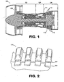
- FIG. 1 is a schematic diagram depicting a representative embodiment of a gas turbine engine 100.
- engine 100 is configured as a turbofan, there is no intention to limit the invention to use with turbofans as use with other types of gas turbine engines is contemplated.
- engine 100 incorporates a fan 102, a compressor section 104, a combustion section 106 and a turbine section 108.
- turbine section 108 includes alternating rows of stationary vanes 110 and rotating blades 112.
- the blades are configured in sets, with each set being attached to a rotatable turbine disk.
- Disk 114 is an exemplary turbine disk that includes blades 116.
- FIG. 2 is a schematic, partially cut-away view depicting a portion of disk 114 with the blades removed.
- disk 114 is configured to create a compound knife edge seal comprising two seals. Specifically, a first set of knife edges 202 forms a first of the seals, and a second set of knife edges 204 forms a second of the seals. Note also that when the blades (not shown) are in installed on the turbine disk, each of the blades also incorporates two knife edges that complete the two annular sets of knife edges that form the compound seal.
- hammer head seals For additional information on knife edge seals of comparable configurations (known as "hammer head seals"), please refer to U.S. Patent Applications, Segmented Fluid Seal Assembly ( U.S.
- Patent Application Number 11/505,165, filed on August 16, 2006 Hammerhead Fluid Seal
- U.S. Patent Application Number 11/146,801, filed on June 7, 2005 Integrated Bladed Fluid Seal
- U.S. Patent Application Number 11/260,357, filed on October 27, 2005 Blade Neck Fluid Seal
- U.S. Patent Application Number 11/146,660, filed on July 7, 2005 Combined Bladed Attachment and Disk Lug Fluid Seal
- U.S. Patent Application Number 11/146,798, filed on July 7, 2005 which are incorporated by reference herein.
- FIG. 3 is a flowchart depicting an embodiment of a method that may be used for repairing IN-100 components.
- the method may be construed as beginning at block 302, in which a knife edge of a gas turbine component formed of IN-100 is provided. This can occur during an overhaul or repair procedure, for example, and may involve disassembly and/or cleaning of a turbine rotor, which includes the disk and attached blades. Thus the disk may be removed from the engine for repair.
- the knife edge can be prepared for welding (block 304). This can include grinding and/or blending of the knife edge so that a surface suitable to receive weld material is available.
- a cladding layer or layers are applied to the knife edge in order to build up a distal surface of the knife edge.
- a laser is used to melt IN-100 powder that is dispensed in a vicinity of the laser.
- the powder is injected co-axially into the laser beam so that the powder is melted and deposited on the knife edge.
- a maximum particle size of the powder is between about 44 ⁇ m (325 standard mesh size) and about 149 ⁇ m (100 standard mesh size), preferably between about 63 ⁇ m (250 standard mesh size) and about 105 ⁇ m (150 standard mesh size).
- depositing of the material may be accomplished with an average power output of the laser of between about 200 Watts and about 1000 Watts, preferably between about 300 Watts and about 600 Watts.
- the function specified in block 306 is then repeated, as desired, to build up one or more layers of IN-100 material on the surface of the component.
- a maximum thickness of each of the layers in some embodiments is between about 0.25 mm and about 1.27 mm, preferably between about 0.51 mm and about 0.64 mm. Such thickness may be considered preferable due to the reduced heat required to produce welds of this thickness.
- the weld is finished, such as by grinding and/or blending, to a desired profile.
- An example of a repair accomplished by the embodiment of FIG. 3 is depicted in FIG. 4 .
- the distal end 402 of a knife edge 404 (which may be on a turbine blade or disk) has been built-up with seven sequentially applied layers (e.g., layer 406) of material.
- a device with an integrated laser and powder applicator capable of 5-axis motion (such as an HC-205 Laser Cladding System manufactured by Huffman) was used to provide the results depicted in FIG. 4 .
- various other devices could be used.
Landscapes
- Engineering & Computer Science (AREA)
- Mechanical Engineering (AREA)
- Physics & Mathematics (AREA)
- Optics & Photonics (AREA)
- Plasma & Fusion (AREA)
- General Engineering & Computer Science (AREA)
- Laser Beam Processing (AREA)
Abstract
Description
- The disclosure generally relates to gas turbine engine repair.
- Turbine blades are typically mounted to a disk that is attached to a rotating spool for rotating the blades. In order to prevent gas from leaking around the distal ends of the blades, knife edge seals can be used. Conventionally, a knife edge seal is formed by a conformable portion of a turbine casing and a complementary-shaped distal end portion of a turbine blade known as "knife edge". In use, the knife edge can contact the turbine casing and, thus, tends to wear over time.
- Traditionally, knife edges that are degraded, e.g., worn beyond prescribed operating limits, are remedied by replacement or repair. In the case of replacement, the entire disk and associated blades are removed from the engine and new disk and blades are installed. In the case of repair, a weld process or thermal spray can be used to build-up material at the wear location. However, some materials, such as IN-100 high-temperature nickel superalloy are not conventionally considered candidates for such repair due to the difficulty of welding IN100 material.
- Methods for repairing a gas turbine engine knife edge seals are provided. In this regard, an exemplary embodiment of a method comprises: providing a knife edge of a gas turbine component, the component comprising IN-100, the knife edge being degraded; directing a laser beam toward the knife edge; and dispensing IN-100 powder such that the IN-100 powder is melted by the laser beam and is deposited on the knife edge.
- Another embodiment of a method comprises: providing a knife edge of a gas turbine component, the component being formed of IN-100, the knife edge being degraded; directing a laser beam toward the knife edge; and injecting IN-100 powder co-axially into the laser beam such that the IN-100 powder is melted by the laser beam and is deposited on the knife edge.
- Still another embodiment of a method comprises: inspecting a knife edge of a gas turbine component, the component being formed of IN-100; determining that the knife edge is degraded; directing a laser beam toward the knife edge; and forming a layer of IN-100 on the knife edge using the laser beam and IN-100 powder.
- An embodiment of a repaired IN-100 gas turbine engine component comprises a knife edge comprising at least one layer of IN-100 material deposited thereon via laser cladding, wherein after laser cladding, the at least one layer has been finished to desired dimensions.
- Other systems, methods, features and/or advantages of this disclosure will be or may become apparent to one with skill in the art upon examination of the following drawings and detailed description. It is intended that all such additional systems, methods, features and/or advantages be included within this description and be within the scope of the present disclosure.
- Many aspects of the disclosure can be better understood with reference to the following drawings. The components in the drawings are not necessarily to scale. Moreover, in the drawings, like reference numerals designate corresponding parts throughout the several views.
-
FIG. 1 is a schematic, cross-sectional view of an embodiment of a gas turbine engine. -
FIG. 2 is a schematic, partially cut-away view of an embodiment of a turbine disk with associated blades removed. -
FIG. 3 is a flowchart depicting an embodiment of method for repairing a gas turbine engine. -
FIG. 4 is schematic diagram depicting layers of IN-100 deposited on a knife edge. - As will be described in detail here, methods for repairing gas turbine engine knife edge seals are provided. In this regard, several embodiments will be described that generally involve the use of powdered metal being melted and then deposited on the degraded end of a knife edge. In some embodiments, the material is built-up as a series of thin layers that can be sequentially applied in order to rebuild the knife edge to suitable operational dimensions. Notably, at least some of these methods may be used with IN-100, which has previously eluded repair by welding techniques.
- Referring now to the drawings,
FIG. 1 is a schematic diagram depicting a representative embodiment of agas turbine engine 100. Althoughengine 100 is configured as a turbofan, there is no intention to limit the invention to use with turbofans as use with other types of gas turbine engines is contemplated. - As shown in
FIG. 1 ,engine 100 incorporates afan 102, acompressor section 104, acombustion section 106 and aturbine section 108. Notably,turbine section 108 includes alternating rows ofstationary vanes 110 and rotatingblades 112. In this embodiment, the blades are configured in sets, with each set being attached to a rotatable turbine disk.Disk 114 is an exemplary turbine disk that includesblades 116. -
FIG. 2 is a schematic, partially cut-away view depicting a portion ofdisk 114 with the blades removed. In this embodiment,disk 114 is configured to create a compound knife edge seal comprising two seals. Specifically, a first set ofknife edges 202 forms a first of the seals, and a second set ofknife edges 204 forms a second of the seals. Note also that when the blades (not shown) are in installed on the turbine disk, each of the blades also incorporates two knife edges that complete the two annular sets of knife edges that form the compound seal. For additional information on knife edge seals of comparable configurations (known as "hammer head seals"), please refer to U.S. Patent Applications, Segmented Fluid Seal Assembly (U.S. Patent Application Number 11/505,165, filed on August 16, 2006 U.S. Patent Application Number 11/146,801, filed on June 7, 2005 U.S. Patent Application Number 11/260,357, filed on October 27, 2005 U.S. Patent Application Number 11/146,660, filed on July 7, 2005 U.S. Patent Application Number 11/146,798, filed on July 7, 2005 - At least some embodiments of turbine disks, such as those using hammer head seals, are formed of IN-100. As is known, materials such as IN-100 are not conventionally considered suitable for weld repair. This is because of a tendency to crack during the application of heat during thermal processing, including plasma arc welding. In this regard,
FIG. 3 is a flowchart depicting an embodiment of a method that may be used for repairing IN-100 components. - As shown in
FIG. 3 , the method may be construed as beginning atblock 302, in which a knife edge of a gas turbine component formed of IN-100 is provided. This can occur during an overhaul or repair procedure, for example, and may involve disassembly and/or cleaning of a turbine rotor, which includes the disk and attached blades. Thus the disk may be removed from the engine for repair. - If it is determined, such as during inspection, that the knife edge requires repair, the knife edge can be prepared for welding (block 304). This can include grinding and/or blending of the knife edge so that a surface suitable to receive weld material is available. In
block 306, a cladding layer or layers are applied to the knife edge in order to build up a distal surface of the knife edge. Specifically, a laser is used to melt IN-100 powder that is dispensed in a vicinity of the laser. In some embodiments, the powder is injected co-axially into the laser beam so that the powder is melted and deposited on the knife edge. In some embodiments, a maximum particle size of the powder is between about 44 µm (325 standard mesh size) and about 149 µm (100 standard mesh size), preferably between about 63 µm (250 standard mesh size) and about 105 µm (150 standard mesh size). - Depending upon material thickness, depositing of the material may be accomplished with an average power output of the laser of between about 200 Watts and about 1000 Watts, preferably between about 300 Watts and about 600 Watts. The function specified in
block 306 is then repeated, as desired, to build up one or more layers of IN-100 material on the surface of the component. Although the number and thickness of such layers can be established as desired, a maximum thickness of each of the layers in some embodiments is between about 0.25 mm and about 1.27 mm, preferably between about 0.51 mm and about 0.64 mm. Such thickness may be considered preferable due to the reduced heat required to produce welds of this thickness. - In
block 308, the weld is finished, such as by grinding and/or blending, to a desired profile. An example of a repair accomplished by the embodiment ofFIG. 3 is depicted inFIG. 4 . - As shown in
FIG. 4 , thedistal end 402 of a knife edge 404 (which may be on a turbine blade or disk) has been built-up with seven sequentially applied layers (e.g., layer 406) of material. It should be noted that a device with an integrated laser and powder applicator capable of 5-axis motion (such as an HC-205 Laser Cladding System manufactured by Huffman) was used to provide the results depicted inFIG. 4 . However, various other devices could be used. - It should be emphasized that the above-described embodiments are merely possible examples of implementations set forth for a clear understanding of the principles of this disclosure. Many variations and modifications may be made to the above-described embodiments without departing substantially from the principles of the disclosure. All such modifications and variations are intended to be included herein within the scope of this disclosure and protected by the accompanying claims.
Claims (14)
- A method for repairing a degraded knife edge (404) of a gas turbine component, the component comprising IN-100, the method comprising:directing a laser beam toward the knife edge (404); anddispensing IN-100 powder such that the IN-100 powder is melted by the laser beam and is deposited on the knife edge.
- The method of claim 1, wherein the IN-100 is deposited on the knife edge (404) in separately formed layers (406).
- The method of claim 1, wherein dispensing IN-100 powder comprises;injecting IN-100 powder co-axially into the laser beam such that the IN-100 powder is melted by the laser beam and is deposited on the knife edge (404).
- The method of claim 3, wherein the IN-100 is deposited on the knife edge in layers.
- The method of claim 2 or 4, wherein a maximum thickness of each of the layers is approximately 1.27 mm.
- The method of claim 2 or 4, wherein a maximum thickness of each of the layers is approximately 0.64 mm.
- The method of any preceding claim, wherein the component comprises at least one of: a blade and a turbine disk.
- The method of any preceding claim, wherein an average power output of the laser is between approximately 200 Watts and approximately 1000 Watts during the step of dispensing.
- The method of claim 1, wherein an average power output of the laser is between approximately 300 Watts and approximately 600 Watts during the step of dispensing.
- The method of any preceding claim, wherein, in dispensing the IN-100 powder, a maximum particle size of the powder is 149 µm.
- The method of any preceding claim, wherein, in dispensing the IN-100 powder, a maximum particle size of the powder is 44 µm.
- The method of any preceding claim, further comprising finishing the knife edge to a desired profile.
- The method of claim 1, further comprising forming additional layers (406) of IN-100, sequentially, on the knife edge (404).
- A repaired IN-100 gas turbine engine component comprising:a knife edge (404) comprising at least one layer (406) of IN-100 material deposited thereon via laser cladding, wherein after laser cladding, the at least one layer (406) has been finished to desired dimensions.
Applications Claiming Priority (1)
| Application Number | Priority Date | Filing Date | Title |
|---|---|---|---|
| US11/782,057 US8089028B2 (en) | 2007-07-24 | 2007-07-24 | Methods for repairing gas turbine engine knife edge seals |
Publications (1)
| Publication Number | Publication Date |
|---|---|
| EP2022597A1 true EP2022597A1 (en) | 2009-02-11 |
Family
ID=39874116
Family Applications (1)
| Application Number | Title | Priority Date | Filing Date |
|---|---|---|---|
| EP08252526A Withdrawn EP2022597A1 (en) | 2007-07-24 | 2008-07-24 | Methods for repairing gas turbine engine knife edge seals |
Country Status (2)
| Country | Link |
|---|---|
| US (1) | US8089028B2 (en) |
| EP (1) | EP2022597A1 (en) |
Cited By (1)
| Publication number | Priority date | Publication date | Assignee | Title |
|---|---|---|---|---|
| EP1985800A3 (en) * | 2007-04-27 | 2012-06-13 | United Technologies Corporation | Dimensional restoration of turbine blade knife edge seals |
Families Citing this family (4)
| Publication number | Priority date | Publication date | Assignee | Title |
|---|---|---|---|---|
| US9283593B2 (en) * | 2011-01-13 | 2016-03-15 | Siemens Energy, Inc. | Selective laser melting / sintering using powdered flux |
| AU2013207997B2 (en) | 2012-01-11 | 2016-04-28 | Fecon, Llc | Wear-resistant cutting teeth, cutting heads and related apparatus |
| WO2014158282A1 (en) | 2013-03-13 | 2014-10-02 | Daum Peter E | Laser deposition using a protrusion technique |
| US12209997B2 (en) | 2022-04-26 | 2025-01-28 | Rtx Corporation | Inspection systems and methods for sealing surfaces |
Citations (5)
| Publication number | Priority date | Publication date | Assignee | Title |
|---|---|---|---|---|
| EP0861927A1 (en) * | 1997-02-24 | 1998-09-02 | Sulzer Innotec Ag | Method for manufacturing single crystal structures |
| EP1348781A1 (en) * | 2002-03-26 | 2003-10-01 | Sulzer Markets and Technology AG | Methode de croissance épitaxiale par irradiation avec un faisceau d'énergie |
| US20040112280A1 (en) * | 2002-04-15 | 2004-06-17 | Thomas Beck | Method for producing monocrystalline structures |
| US20050120941A1 (en) * | 2003-12-04 | 2005-06-09 | Yiping Hu | Methods for repair of single crystal superalloys by laser welding and products thereof |
| EP1688211A2 (en) * | 2005-02-03 | 2006-08-09 | United Technologies Corporation | Plasma arc weld repair of high nickel metal alloys |
Family Cites Families (18)
| Publication number | Priority date | Publication date | Assignee | Title |
|---|---|---|---|---|
| US4159410A (en) * | 1977-06-13 | 1979-06-26 | General Electric Company | Method and apparatus for applying molten filler material |
| US4323756A (en) * | 1979-10-29 | 1982-04-06 | United Technologies Corporation | Method for fabricating articles by sequential layer deposition |
| US4426191A (en) * | 1980-05-16 | 1984-01-17 | United Technologies Corporation | Flow directing assembly for a gas turbine engine |
| US4483054A (en) * | 1982-11-12 | 1984-11-20 | United Technologies Corporation | Method for making a drum rotor |
| US4743165A (en) * | 1986-10-22 | 1988-05-10 | United Technologies Corporation | Drum rotors for gas turbine engines |
| US4878953A (en) * | 1988-01-13 | 1989-11-07 | Metallurgical Industries, Inc. | Method of refurbishing cast gas turbine engine components and refurbished component |
| US4924581A (en) * | 1988-11-22 | 1990-05-15 | Techniair, Inc. | Turbine air seal repair process |
| US5038014A (en) * | 1989-02-08 | 1991-08-06 | General Electric Company | Fabrication of components by layered deposition |
| US5106010A (en) * | 1990-09-28 | 1992-04-21 | Chromalloy Gas Turbine Corporation | Welding high-strength nickel base superalloys |
| US5071054A (en) * | 1990-12-18 | 1991-12-10 | General Electric Company | Fabrication of cast articles from high melting temperature superalloy compositions |
| US5449536A (en) * | 1992-12-18 | 1995-09-12 | United Technologies Corporation | Method for the application of coatings of oxide dispersion strengthened metals by laser powder injection |
| US6422815B1 (en) * | 2000-03-02 | 2002-07-23 | General Electric Company | Turbine air seal replacement rings |
| US6884964B2 (en) * | 2003-01-09 | 2005-04-26 | General Electric Company | Method of weld repairing a component and component repaired thereby |
| US7259353B2 (en) * | 2004-09-30 | 2007-08-21 | Honeywell International, Inc. | Compact coaxial nozzle for laser cladding |
| US20070023402A1 (en) * | 2005-07-26 | 2007-02-01 | United Technologies Corporation | Methods for repairing workpieces using microplasma spray coating |
| US20060219330A1 (en) * | 2005-03-29 | 2006-10-05 | Honeywell International, Inc. | Nickel-based superalloy and methods for repairing gas turbine components |
| US20060219329A1 (en) * | 2005-03-29 | 2006-10-05 | Honeywell International, Inc. | Repair nickel-based superalloy and methods for refurbishment of gas turbine components |
| US8884182B2 (en) * | 2006-12-11 | 2014-11-11 | General Electric Company | Method of modifying the end wall contour in a turbine using laser consolidation and the turbines derived therefrom |
-
2007
- 2007-07-24 US US11/782,057 patent/US8089028B2/en active Active
-
2008
- 2008-07-24 EP EP08252526A patent/EP2022597A1/en not_active Withdrawn
Patent Citations (5)
| Publication number | Priority date | Publication date | Assignee | Title |
|---|---|---|---|---|
| EP0861927A1 (en) * | 1997-02-24 | 1998-09-02 | Sulzer Innotec Ag | Method for manufacturing single crystal structures |
| EP1348781A1 (en) * | 2002-03-26 | 2003-10-01 | Sulzer Markets and Technology AG | Methode de croissance épitaxiale par irradiation avec un faisceau d'énergie |
| US20040112280A1 (en) * | 2002-04-15 | 2004-06-17 | Thomas Beck | Method for producing monocrystalline structures |
| US20050120941A1 (en) * | 2003-12-04 | 2005-06-09 | Yiping Hu | Methods for repair of single crystal superalloys by laser welding and products thereof |
| EP1688211A2 (en) * | 2005-02-03 | 2006-08-09 | United Technologies Corporation | Plasma arc weld repair of high nickel metal alloys |
Cited By (1)
| Publication number | Priority date | Publication date | Assignee | Title |
|---|---|---|---|---|
| EP1985800A3 (en) * | 2007-04-27 | 2012-06-13 | United Technologies Corporation | Dimensional restoration of turbine blade knife edge seals |
Also Published As
| Publication number | Publication date |
|---|---|
| US20090026183A1 (en) | 2009-01-29 |
| US8089028B2 (en) | 2012-01-03 |
Similar Documents
| Publication | Publication Date | Title |
|---|---|---|
| US8365405B2 (en) | Preforms and related methods for repairing abradable seals of gas turbine engines | |
| US6491208B2 (en) | Cold spray repair process | |
| JP4301402B2 (en) | How to repair a gas turbine engine stationary shroud using laser cladding | |
| EP2540961B1 (en) | Abrasive airfoil tip | |
| US6905728B1 (en) | Cold gas-dynamic spray repair on gas turbine engine components | |
| EP3415718B1 (en) | Gas turbine engine components with air-cooling features, and related methods of manufacturing the same | |
| US9145787B2 (en) | Rotatable component, coating and method of coating the rotatable component of an engine | |
| US20050235493A1 (en) | In-frame repair of gas turbine components | |
| US20170009584A1 (en) | Systems and Methods for Turbine Blade Repair | |
| US20070044306A1 (en) | Superalloy repair methods | |
| CN104937217A (en) | Sealing system for use in a turbomachine and method of manufacturing the same | |
| JP2004150432A (en) | Method of repairing gas turbine engine stationary shroud using plasma transferable arc welding | |
| US20050220995A1 (en) | Cold gas-dynamic spraying of wear resistant alloys on turbine blades | |
| EP2753799B1 (en) | Nutreparatur einer rotordrahtdichtung | |
| EP2022597A1 (en) | Methods for repairing gas turbine engine knife edge seals | |
| JP2006307856A (en) | Stator blade, turbo machine provided with blade, method for repairing blade | |
| JP2022514724A (en) | Preparations for repair of service run gas turbine parts | |
| CN109312624B (en) | Method for repairing a trailing edge of an airfoil to include a spout slot therein | |
| EP2113633A2 (en) | Method to weld repair blade outer air seals | |
| US20040261265A1 (en) | Method for improving the wear resistance of a support region between a turbine outer case and a supported turbine vane | |
| EP3056590A1 (en) | Blade restoration using shroud plating and obtained product | |
| US20170198584A1 (en) | Systems and methods for repairing a component of a rotary machine | |
| US20100284793A1 (en) | Method of electrical discharge surface repair of a variable vane trunnion | |
| JP2002206405A (en) | Steam turbine | |
| Liburdi et al. | Enabling Technologies for Advanced Turbine Component Life Extension |
Legal Events
| Date | Code | Title | Description |
|---|---|---|---|
| PUAI | Public reference made under article 153(3) epc to a published international application that has entered the european phase |
Free format text: ORIGINAL CODE: 0009012 |
|
| AK | Designated contracting states |
Kind code of ref document: A1 Designated state(s): AT BE BG CH CY CZ DE DK EE ES FI FR GB GR HR HU IE IS IT LI LT LU LV MC MT NL NO PL PT RO SE SI SK TR |
|
| AX | Request for extension of the european patent |
Extension state: AL BA MK RS |
|
| 17P | Request for examination filed |
Effective date: 20090514 |
|
| 17Q | First examination report despatched |
Effective date: 20090617 |
|
| AKX | Designation fees paid |
Designated state(s): DE GB |
|
| STAA | Information on the status of an ep patent application or granted ep patent |
Free format text: STATUS: THE APPLICATION IS DEEMED TO BE WITHDRAWN |
|
| 18D | Application deemed to be withdrawn |
Effective date: 20120703 |