EP2022065B1 - Transformer tank with system for preventing rupture of the transformer tank - Google Patents
Transformer tank with system for preventing rupture of the transformer tank Download PDFInfo
- Publication number
- EP2022065B1 EP2022065B1 EP06799142.2A EP06799142A EP2022065B1 EP 2022065 B1 EP2022065 B1 EP 2022065B1 EP 06799142 A EP06799142 A EP 06799142A EP 2022065 B1 EP2022065 B1 EP 2022065B1
- Authority
- EP
- European Patent Office
- Prior art keywords
- tank
- rupture
- transformer tank
- transformer
- relief
- Prior art date
- Legal status (The legal status is an assumption and is not a legal conclusion. Google has not performed a legal analysis and makes no representation as to the accuracy of the status listed.)
- Ceased
Links
Images



Classifications
-
- H—ELECTRICITY
- H01—ELECTRIC ELEMENTS
- H01F—MAGNETS; INDUCTANCES; TRANSFORMERS; SELECTION OF MATERIALS FOR THEIR MAGNETIC PROPERTIES
- H01F27/00—Details of transformers or inductances, in general
- H01F27/08—Cooling; Ventilating
- H01F27/10—Liquid cooling
- H01F27/12—Oil cooling
- H01F27/14—Expansion chambers; Oil conservators; Gas cushions; Arrangements for purifying, drying, or filling
-
- H—ELECTRICITY
- H01—ELECTRIC ELEMENTS
- H01F—MAGNETS; INDUCTANCES; TRANSFORMERS; SELECTION OF MATERIALS FOR THEIR MAGNETIC PROPERTIES
- H01F27/00—Details of transformers or inductances, in general
- H01F27/34—Special means for preventing or reducing unwanted electric or magnetic effects, e.g. no-load losses, reactive currents, harmonics, oscillations, leakage fields
- H01F27/36—Electric or magnetic shields or screens
-
- H—ELECTRICITY
- H01—ELECTRIC ELEMENTS
- H01F—MAGNETS; INDUCTANCES; TRANSFORMERS; SELECTION OF MATERIALS FOR THEIR MAGNETIC PROPERTIES
- H01F27/00—Details of transformers or inductances, in general
- H01F27/40—Structural association with built-in electric component, e.g. fuse
- H01F27/402—Association of measuring or protective means
- H01F2027/404—Protective devices specially adapted for fluid filled transformers
-
- H—ELECTRICITY
- H01—ELECTRIC ELEMENTS
- H01F—MAGNETS; INDUCTANCES; TRANSFORMERS; SELECTION OF MATERIALS FOR THEIR MAGNETIC PROPERTIES
- H01F27/00—Details of transformers or inductances, in general
- H01F27/02—Casings
- H01F27/025—Constructional details relating to cooling
-
- H—ELECTRICITY
- H01—ELECTRIC ELEMENTS
- H01F—MAGNETS; INDUCTANCES; TRANSFORMERS; SELECTION OF MATERIALS FOR THEIR MAGNETIC PROPERTIES
- H01F27/00—Details of transformers or inductances, in general
- H01F27/08—Cooling; Ventilating
- H01F27/10—Liquid cooling
- H01F27/12—Oil cooling
-
- H—ELECTRICITY
- H01—ELECTRIC ELEMENTS
- H01F—MAGNETS; INDUCTANCES; TRANSFORMERS; SELECTION OF MATERIALS FOR THEIR MAGNETIC PROPERTIES
- H01F27/00—Details of transformers or inductances, in general
- H01F27/28—Coils; Windings; Conductive connections
- H01F27/32—Insulating of coils, windings, or parts thereof
- H01F27/321—Insulating of coils, windings, or parts thereof using a fluid for insulating purposes only
Definitions
- the present invention relates to a transformer tank with a system tor preventing the transformer tank from rupturing, which increases the limit of the deformation of a tank constituting a transformer, thus reducing the pressure generated in the transformer, and which increases the number of rupture discs installed per unit area, thus eliminating pressure.
- transformers are pieces of electrical equipment which change a voltage to a higher or lower voltage.
- the transformers are classified into oil-immersed transformers and dry-type transformers according to the kind of insulating material.
- An oil-immersed transformer filled with insulating oil is widely used.
- the oil-immersed transformer includes a high-voltage winding, a low-voltage winding, an iron core, insulating oil, a tank, and other components.
- the oil-immersed transformer is constructed so that electric current is supplied through a bushing mounted to a bushing turret.
- a breakdown occurs in the transformer due to abnormal voltage caused by lightning or a switching surge, and thus an arc is generated, some of the insulating oil filled in the tank for insulating or cooling the transformer is instantaneously burnt. Due to the combustion of the insulating oil, the internal pressure in the transformer is suddenly increased. Such pressure ruptures the transformer tank, and air fed through the ruptured portion is supplied to an arc generating part, so that a fire may break out. Further, the insulating oil escapes out of the ruptured tank, thus causing environmental pollution.
- the conventional method of interrupting the supply of electricity to the transformer has been widely used.
- the tank may rupture even due to the rise in pressure occurring prior to interrupting the electricity supply, and thus a device for mechanically eliminating the pressure is required.
- an attempt to eliminate localized pressure has been made using rupture discs.
- the arc generating point may be far from the rupture discs.
- the tank may rupture.
- the number of rupture discs is not sufficient compared to the arc energy, so that the tank may rupture before the pressure eliminating operation is performed.
- US 6 804 092 B1 discloses a transformer tank with a system for preventing a rupture of the transformer tank, which system is provided on the transformer tank and prevents a rupture of the transformer tank due to a sudden rise in pressure in the transformer tank, the system comprising
- the system may comprise further rupture discs (35, 42) mounted to respective pipes extending outwards from the transformer tank (shown in Fig.4 ), which rupture discs rupture when the pressure in the transformer tank reaches a predetermined pressure level, thus opening passages.
- the pipes are connected to the pipe of the rupture disc (1).
- the rupture detection means is an electrical conducting wire (11) on the rupture disc which is cut when the disc ruptures.
- JP 56050502 discloses a transformer tank with a system for preventing a rupture of the transformer tank, wherein an oil gauge (7) for rupture detection is provided.
- JP 10294226 , US 3 827 018 , DE 44 46 716 Cl and US 2 923 905 disclose a transformer tank with shielding plates provided on the inner wall side of the tank in order to shield magnetic fields generated in the interior of the tank.
- an object of the present invention is to provide a system for preventing the rupture of a transformer tank wherever the arc is generated in the tank, which increases a limit of the deformation of a tank constituting a transformer, thus primarily preventing a sudden rise in pressure, and which increases the number of rupture discs installed per unit area, thus preventing the rupture of the tank.
- the present invention provides transformer tank with a system for preventing a rupture of a transformer tank according to present claim 1.
- FIG. 1 is a view showing the construction of a rupture prevention system, according to the preferred embodiment of the present invention
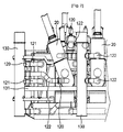
- FIG. 2 is a front view showing part of a transformer equipped with the rupture prevention system of FIG. 1
- FIG. 3 is a perspective view showing the transformer equipped with the rupture prevention system of FIG. 1
- FIG. 4 is a perspective view showing the state where shielding plates are installed by a support part of the present invention
- FIG. 5 is a detailed view showing portion 'A' of FIG. 4 .
- a rupture prevention system includes a support part 110, rupture discs 120, relief tanks 130, and oil gauges 140.
- a rupture prevention system increases the limit of deformation of a transformer tank 10 using the support part 110, and is provided with a plurality of rupture discs 120, thus efficiently preventing the transformer tank 10 from rupturing due to a sudden rise in internal pressure.
- the support part 110 is mounted to the inner surface of the tank 10 constituting the transformer, thus supporting shielding plates 111. Meanwhile, the shielding plates 111 are installed in the transformer tank 10 to absorb a magnetic field. In the prior art, the shielding plates 111 are directly mounted to the tank 10, thus increasing the strength of the tank 10, and reducing the limit of the deformation of the tank 10 due to the pressure. However, according to the present invention, the support part 110 is mounted to the inner surface of the tank 10 so as to prevent the shielding plates 111 from being directly mounted to the tank 10. The support part 110 serves to support the shielding plates 111. In a detailed description, the shielding plates 111 are welded to the front surface of the support part 110.
- the support part 110 Four corners of the support part 110 are bent backwards a predetermined length, thus providing welding parts 113.
- the welding parts 113 are welded to the inner wall of the transformer.
- Pressure transmitting holes 112 for transmitting pressure to the rupture discs 120 are formed at positions corresponding to pipes 121 on which the rupture discs 120 are mounted.
- the support part 110 defines space for flowing insulating oil between the welding parts 113 which are bent toward the back of the support part and the inner wall of the transformer, thus helping cool the transformer.
- the support part 110 prevents the shielding plates 111 from being directly mounted to the tank 10, thus allowing the tank 10 to sensitively react to variations in internal pressure.
- the rupture discs 120 rupture when the internal pressure of the transformer exceeds a predetermined pressure level, thus eliminating the internal pressure.
- the rupture discs 120 are mounted respectively on the plurality of pipes 121 extending outwards from the transformer tank 10. Since the rupture discs 120 mounted to the respective pipes 121 are already known, the detailed description of the rupture discs will be omitted. In the prior art, one to three rupture discs 120 were installed. However, according to the present invention, the deformation of the transformer tank fundamentally reduces the internal pressure for 0.08 seconds when an arc is generated. The remaining pressure is secondarily reduced by the rupture discs which are almost simultaneously operated. Thus, the number of rupture discs is calculated so that the increased pressure does not reach the rupture pressure of the tank.
- the number of rupture discs is multiplied by a factor of 5 or over, compared to the conventional number of rupture discs per unit area.
- the rupture discs are uniformly installed throughout the surface of the transformer, so that they are operated regardless of the arc generating position, even in the case the rupture discs are distant from the arc generating position.
- the tank to which the invention is applied is made of a high-strength steel plate that has rupture limit pressure twice as high as a conventional tank.
- the rupture discs 120 may be installed to eliminate pressure generated in the bushing turrets 20.
- subsidiary pipes 122 are installed to couple the bushing turrets 20 to the relief tanks 130.
- the rupture discs 120 are mounted to the subsidiary pipes 122, and rupture when the internal pressure of the bushing turrets 20 rises and exceeds a predetermined pressure level, thus eliminating the pressure.
- the relief tanks 130 provide space for storing insulating oil discharged through passages which are formed by the rupture of the rupture discs 120.
- the relief tanks having a cylindrical shape are vertically installed at a position neighboring the transformer, and are coupled to the transformer tank 110 via the pipes 121.
- a flexible tube 123 which is freely bendable is provided on one end of each pipe 121 and is coupled to the relief tank 130, thus allowing the pipes 121 to be more easily coupled to the relief tanks 130.
- the relief tanks 130 are coupled to each other by coupling pipes 131. When some of the rupture discs 120 are ruptured and passages are formed, insulating oil flows concentratedly into the associated relief tanks 130. In order to distribute the insulating oil, the relief tanks 130 are coupled to each other via the coupling pipes 131, so that the discharged insulating oil is distributed to the several relief tanks 130 to be stored therein.
- each of the relief tanks 130 is constructed so that the bottom surface 130a of the relief tank is inclined toward each oil gauge 140. This construction allows the oil gauge 140 to more rapidly detect whether insulating oil is being discharged or not.
- an opening 132 is formed in the upper end of each relief tank 130 to discharge combustion gas fed together with the insulating oil. The opening 132 is formed toward the transformer 100 to prevent a worker from being injured.
- a steel net 133 is installed in the opening 132 to prevent impurities, insects, and small animals from entering the opening 132.
- a manhole 134 is formed at a predetermined position in each relief tank 130, so that a worker enters the manhole and thus checks the interior and repairs the oil gauge 140.
- the oil gauge 140 is mounted to the lower portion in each relief tank 130, and generates a signal when the insulating oil flows into the relief tank 130, thus informing a manager of the rupture of each rupture disc 120 and the discharge of the insulating oil.
- the insulation in the transformer may break and the pressure in the transformer may increase suddenly.
- the transformer tank 10 is deformed and thus expands, thus primarily reducing the pressure, because, as described above, the shielding plates 111 are not directly mounted to the transformer tank 10 using the support part 110 so as to increase the limit of the deformation of the transformer tank 10.
- the pressure is reduced due to the deformation of the transformer tank 10, and simultaneously, the rupture discs 120, which rupture when a predetermined pressure level is reached, are operated, so that the combustion gas and the insulating oil are discharged through the pipes 121 to the relief tanks 130, thus eliminating the pressure generated in the transformer.
- the oil gauges 140 generate signals. In response to the signals, a manager can rapidly check the condition of the transformer.
- the limit of the deformation of a tank constituting a transformer is increased, and in addition, the number of rupture discs installed per unit area is increased, thus more effectively eliminating internal pressure caused by abnormal voltage. Moreover, even when an arc is generated at a position distant from the rupture discs, the transformer tank is deformed, thus eliminating pressure, therefore allowing the transformer to be more safely manufactured.
Landscapes
- Engineering & Computer Science (AREA)
- Power Engineering (AREA)
- Housings And Mounting Of Transformers (AREA)
Description
- The present invention relates to a transformer tank with a system tor preventing the transformer tank from rupturing, which increases the limit of the deformation of a tank constituting a transformer, thus reducing the pressure generated in the transformer, and which increases the number of rupture discs installed per unit area, thus eliminating pressure.
- Generally, transformers are pieces of electrical equipment which change a voltage to a higher or lower voltage. The transformers are classified into oil-immersed transformers and dry-type transformers according to the kind of insulating material. An oil-immersed transformer filled with insulating oil is widely used. The oil-immersed transformer includes a high-voltage winding, a low-voltage winding, an iron core, insulating oil, a tank, and other components.
- The oil-immersed transformer is constructed so that electric current is supplied through a bushing mounted to a bushing turret. When a breakdown occurs in the transformer due to abnormal voltage caused by lightning or a switching surge, and thus an arc is generated, some of the insulating oil filled in the tank for insulating or cooling the transformer is instantaneously burnt. Due to the combustion of the insulating oil, the internal pressure in the transformer is suddenly increased. Such pressure ruptures the transformer tank, and air fed through the ruptured portion is supplied to an arc generating part, so that a fire may break out. Further, the insulating oil escapes out of the ruptured tank, thus causing environmental pollution.
- In order to prevent the tank from rupturing, the conventional method of interrupting the supply of electricity to the transformer has been widely used. However, the tank may rupture even due to the rise in pressure occurring prior to interrupting the electricity supply, and thus a device for mechanically eliminating the pressure is required. Thus, an attempt to eliminate localized pressure has been made using rupture discs. However, in the case of a large transformer, the arc generating point may be far from the rupture discs. Hence, before the pressure eliminating operation using the rupture discs is conducted, the tank may rupture. Further, the number of rupture discs is not sufficient compared to the arc energy, so that the tank may rupture before the pressure eliminating operation is performed.
-
US 6 804 092 B1 discloses a transformer tank with a system for preventing a rupture of the transformer tank, which system is provided on the transformer tank and prevents a rupture of the transformer tank due to a sudden rise in pressure in the transformer tank, the system comprising - a rupture disc (1) (cf.
Fig.3 ) mounted to a pipe (18) extending outwards from the transformer tank (14), and ruptured when the pressure in the transformer tank (14) reaches a predetermined pressure level, thus opening a passage; - a relief tank (19) (cf.
Fig.3 ) vertically installed at a position neighbouring the transformer tank, and coupled to the pipe, thus providing space for storing insulating oil; and - a rupture detection means (11) (cf. col.4, line 59-63; col.7, line 12-14) generating a signal when the insulating oil flows into the relief tank, thus informing a manager of rupture of each of the rupture discs and discharge of the insulating oil.
- Further, the system may comprise further rupture discs (35, 42) mounted to respective pipes extending outwards from the transformer tank (shown in
Fig.4 ), which rupture discs rupture when the pressure in the transformer tank reaches a predetermined pressure level, thus opening passages. The pipes are connected to the pipe of the rupture disc (1). - The rupture detection means is an electrical conducting wire (11) on the rupture disc which is cut when the disc ruptures.
-
JP 56050502 -
JP 10294226 US 3 827 018 ,DE 44 46 716 Cl andUS 2 923 905 disclose a transformer tank with shielding plates provided on the inner wall side of the tank in order to shield magnetic fields generated in the interior of the tank. In particular, it is disclosed that is it particularly advantageous to mount the magnetic shielding plate on a support, which support plate is mounted on the tank wall, so that the shielding plate is not directly attached to the transformer tank wall. - Accordingly, the present invention has been made keeping in mind the above problems occurring in the prior art, and an object of the present invention is to provide a system for preventing the rupture of a transformer tank wherever the arc is generated in the tank, which increases a limit of the deformation of a tank constituting a transformer, thus primarily preventing a sudden rise in pressure, and which increases the number of rupture discs installed per unit area, thus preventing the rupture of the tank.
- In order to accomplish the object, the present invention provides transformer tank with a system for preventing a rupture of a transformer tank according to present claim 1.
- Hereinafter, the preferred embodiment of the present invention will be described in detail with reference to the accompanying drawings. Herein, detailed descriptions of known functions or constructions will be omitted so that those skilled in the art can clearly understand the gist of the invention.
-
FIG. 1 is a view showing the construction of a rupture prevention system, according to the preferred embodiment of the present invention,FIG. 2 is a front view showing part of a transformer equipped with the rupture prevention system ofFIG. 1 ,FIG. 3 is a perspective view showing the transformer equipped with the rupture prevention system ofFIG. 1 ,FIG. 4 is a perspective view showing the state where shielding plates are installed by a support part of the present invention, andFIG. 5 is a detailed view showing portion 'A' ofFIG. 4 . - Referring to
FIGS. 1 to 5 , a rupture prevention system according to the preferred embodiment of the present invention includes asupport part 110,rupture discs 120,relief tanks 130, andoil gauges 140. Such a rupture prevention system increases the limit of deformation of atransformer tank 10 using thesupport part 110, and is provided with a plurality ofrupture discs 120, thus efficiently preventing thetransformer tank 10 from rupturing due to a sudden rise in internal pressure. - The
support part 110 is mounted to the inner surface of thetank 10 constituting the transformer, thus supportingshielding plates 111. Meanwhile, theshielding plates 111 are installed in thetransformer tank 10 to absorb a magnetic field. In the prior art, theshielding plates 111 are directly mounted to thetank 10, thus increasing the strength of thetank 10, and reducing the limit of the deformation of thetank 10 due to the pressure. However, according to the present invention, thesupport part 110 is mounted to the inner surface of thetank 10 so as to prevent theshielding plates 111 from being directly mounted to thetank 10. Thesupport part 110 serves to support theshielding plates 111. In a detailed description, theshielding plates 111 are welded to the front surface of thesupport part 110. Four corners of thesupport part 110 are bent backwards a predetermined length, thus providingwelding parts 113. Thewelding parts 113 are welded to the inner wall of the transformer.Pressure transmitting holes 112 for transmitting pressure to therupture discs 120 are formed at positions corresponding topipes 121 on which therupture discs 120 are mounted. Thesupport part 110 defines space for flowing insulating oil between thewelding parts 113 which are bent toward the back of the support part and the inner wall of the transformer, thus helping cool the transformer. Thesupport part 110 prevents theshielding plates 111 from being directly mounted to thetank 10, thus allowing thetank 10 to sensitively react to variations in internal pressure. - The rupture discs 120 rupture when the internal pressure of the transformer exceeds a predetermined pressure level, thus eliminating the internal pressure. The
rupture discs 120 are mounted respectively on the plurality ofpipes 121 extending outwards from thetransformer tank 10. Since therupture discs 120 mounted to therespective pipes 121 are already known, the detailed description of the rupture discs will be omitted. In the prior art, one to threerupture discs 120 were installed. However, according to the present invention, the deformation of the transformer tank fundamentally reduces the internal pressure for 0.08 seconds when an arc is generated. The remaining pressure is secondarily reduced by the rupture discs which are almost simultaneously operated. Thus, the number of rupture discs is calculated so that the increased pressure does not reach the rupture pressure of the tank. This means that the number of rupture discs is multiplied by a factor of 5 or over, compared to the conventional number of rupture discs per unit area. The rupture discs are uniformly installed throughout the surface of the transformer, so that they are operated regardless of the arc generating position, even in the case the rupture discs are distant from the arc generating position. Moreover, the tank to which the invention is applied is made of a high-strength steel plate that has rupture limit pressure twice as high as a conventional tank. When bushingturrets 20 supplying an electric current to the transformer have a large size, therupture discs 120 may be installed to eliminate pressure generated in thebushing turrets 20. In a detailed description,subsidiary pipes 122 are installed to couple thebushing turrets 20 to therelief tanks 130. Therupture discs 120 are mounted to thesubsidiary pipes 122, and rupture when the internal pressure of thebushing turrets 20 rises and exceeds a predetermined pressure level, thus eliminating the pressure. - The
relief tanks 130 provide space for storing insulating oil discharged through passages which are formed by the rupture of therupture discs 120. The relief tanks having a cylindrical shape are vertically installed at a position neighboring the transformer, and are coupled to thetransformer tank 110 via thepipes 121. Aflexible tube 123 which is freely bendable is provided on one end of eachpipe 121 and is coupled to therelief tank 130, thus allowing thepipes 121 to be more easily coupled to therelief tanks 130. Therelief tanks 130 are coupled to each other by coupling pipes 131. When some of therupture discs 120 are ruptured and passages are formed, insulating oil flows concentratedly into the associatedrelief tanks 130. In order to distribute the insulating oil, therelief tanks 130 are coupled to each other via the coupling pipes 131, so that the discharged insulating oil is distributed to theseveral relief tanks 130 to be stored therein. - Meanwhile, each of the
relief tanks 130 is constructed so that thebottom surface 130a of the relief tank is inclined toward eachoil gauge 140. This construction allows theoil gauge 140 to more rapidly detect whether insulating oil is being discharged or not. Further, anopening 132 is formed in the upper end of eachrelief tank 130 to discharge combustion gas fed together with the insulating oil. Theopening 132 is formed toward the transformer 100 to prevent a worker from being injured. Asteel net 133 is installed in theopening 132 to prevent impurities, insects, and small animals from entering theopening 132. Further, amanhole 134 is formed at a predetermined position in eachrelief tank 130, so that a worker enters the manhole and thus checks the interior and repairs theoil gauge 140. - The
oil gauge 140 is mounted to the lower portion in eachrelief tank 130, and generates a signal when the insulating oil flows into therelief tank 130, thus informing a manager of the rupture of eachrupture disc 120 and the discharge of the insulating oil. - The operation of the system for preventing the rupture of the transformer tank, which is constructed as described above, will be described in the following.
- For various reasons, the insulation in the transformer may break and the pressure in the transformer may increase suddenly. At this time, the
transformer tank 10 is deformed and thus expands, thus primarily reducing the pressure, because, as described above, the shieldingplates 111 are not directly mounted to thetransformer tank 10 using thesupport part 110 so as to increase the limit of the deformation of thetransformer tank 10. The pressure is reduced due to the deformation of thetransformer tank 10, and simultaneously, therupture discs 120, which rupture when a predetermined pressure level is reached, are operated, so that the combustion gas and the insulating oil are discharged through thepipes 121 to therelief tanks 130, thus eliminating the pressure generated in the transformer. Meanwhile, when the insulating oil discharged through thepipes 121 flows into therelief tanks 130, the oil gauges 140 generate signals. In response to the signals, a manager can rapidly check the condition of the transformer. - Although the preferred embodiment according to the present invention has been disclosed with reference to the accompanying drawings, the invention is not limited to the embodiments illustrated in the drawings, and those skilled in the art will appreciate that various modifications are possible, within the scope of the invention as disclosed in the accompanying claims.
- As described above, the limit of the deformation of a tank constituting a transformer is increased, and in addition, the number of rupture discs installed per unit area is increased, thus more effectively eliminating internal pressure caused by abnormal voltage. Moreover, even when an arc is generated at a position distant from the rupture discs, the transformer tank is deformed, thus eliminating pressure, therefore allowing the transformer to be more safely manufactured.
-
-
FIG. 1 is a view showing the construction of a rupture prevention system, according to the preferred embodiment of the present invention, -
FIG. 2 is a front view showing part of a transformer equipped with the rupture prevention system ofFIG. 1 , -
FIG. 3 is a perspective view showing the transformer equipped with the rupture prevention system ofFIG. 1 , -
FIG. 4 is a perspective view showing the state where shielding plates are installed by a support part of the present invention, and -
FIG. 5 is a detailed view showing portion 'A' ofFIG. 4 . -
- (10): tank (20): bushing turret
- (100): transformer (110): support part
- (111): shielding plate (112): pressure transmitting hole
- (113): welding part
- (120): rupture disc (121): pipe
- (122): subsidiary pipe (123): flexible tube
- (130): relief tank (131): coupling pipe
- (132): opening (133): steel net
- (140): oil gauge
Claims (4)
- A transformer tank (10) with a system for preventing a rupture of the transformer tank, which system is provided on the transformer tank and prevents a rupture of the transformer tank due to a sudden rise in pressure in the transformer tank, the system comprising:a support part (110) and a shielding plate (111) installed in the transformer tank, the support part supporting the shielding plate for absorbing a magnetic field so that the shielding plate is not directly attached to the transformer tank;a plurality of rupture discs (120) and a plurality of pipes (121) extending outwards from the transformer tank, the plurality of rupture discs mounted, respectively, to the plurality of pipes extending outwards from the transformer tank, and ruptured when pressure in the transformer tank reaches a predetermined pressure level, thus opening passages of the plurality of pipes;a plurality of relief tanks (130) vertically installed at a position neighboring the transformer tank, and coupled respectively to the plurality of pipes, thus providing space for storing insulating oil; andan oil gauge (140) mounted at a lower position in each of the plurality of relief tanks, and generating a signal when the insulating oil flows into a relief tank of the plurality of relief tanks, thus informing a manager of rupture of each of the rupture discs and discharge of the insulating oil;wherein the shielding plate is welded to a front surface of the support part, and the support part has a plurality of pressure transmitting holes, (112), each at a position corresponding to a pipe of the plurality of pipes, so that the pressure in the transformer tank is transmitted to a respective rupture disc of the plurality of rupture discs, four corners of the support part being bent backwards a predetermined length, thus providing welding parts welded to an inner wall of the transformer tank.
- The transformer tank with the system for preventing rupture according to claim 1, wherein the plurality of relief tanks are coupled to each other via coupling pipes, and each of the plurality of relief tanks is constructed so that a bottom surface in the relief tank is inclined toward the oil gauge, and comprises an opening provided on an upper end of the relief tank to discharge combustion gas entering along with the insulating oil, with a steel net provided in the opening to prevent impurities, insects, and small animals from entering through the opening.
- The transformer tank with the system for preventing rupture according to claim 1, wherein each of the plurality of pipes is coupled to a corresponding relief tank of the plurality of relief tanks via a flexible tube (123) which is freely deformable.
- The transformer tank with the system for preventing rupture according to claim 1, the system further comprising:a subsidiary pipe (122), a bushing turrert (20) and an additional rupture disc (120), the subsidiary pipe coupling the bushing turret, supplying an electric current to the transformer, to a relief tank of the plurality of relief tanks, the additional rupture disc being mounted to the subsidiary pipe.
Applications Claiming Priority (2)
| Application Number | Priority Date | Filing Date | Title |
|---|---|---|---|
| KR1020060049584A KR100754740B1 (en) | 2006-06-01 | 2006-06-01 | Enclosure burst protection device of transformer |
| PCT/KR2006/004062 WO2007139252A1 (en) | 2006-06-01 | 2006-10-10 | System for preventing rupture of transformer tank |
Publications (3)
| Publication Number | Publication Date |
|---|---|
| EP2022065A1 EP2022065A1 (en) | 2009-02-11 |
| EP2022065A4 EP2022065A4 (en) | 2011-12-07 |
| EP2022065B1 true EP2022065B1 (en) | 2016-10-05 |
Family
ID=38736236
Family Applications (1)
| Application Number | Title | Priority Date | Filing Date |
|---|---|---|---|
| EP06799142.2A Ceased EP2022065B1 (en) | 2006-06-01 | 2006-10-10 | Transformer tank with system for preventing rupture of the transformer tank |
Country Status (15)
| Country | Link |
|---|---|
| US (1) | US7902950B2 (en) |
| EP (1) | EP2022065B1 (en) |
| JP (1) | JP4714785B2 (en) |
| KR (1) | KR100754740B1 (en) |
| CN (1) | CN101432826B (en) |
| AT (1) | AT506207B1 (en) |
| BR (1) | BRPI0621746B1 (en) |
| CA (1) | CA2651750C (en) |
| DE (1) | DE112006003886B4 (en) |
| MX (1) | MX2008015013A (en) |
| RU (1) | RU2383981C1 (en) |
| SE (1) | SE533227C2 (en) |
| TR (1) | TR200809054T1 (en) |
| WO (1) | WO2007139252A1 (en) |
| ZA (1) | ZA200809424B (en) |
Families Citing this family (15)
| Publication number | Priority date | Publication date | Assignee | Title |
|---|---|---|---|---|
| US8710946B2 (en) * | 2008-09-17 | 2014-04-29 | General Electric Company | Rupture resistant system |
| US8717134B2 (en) * | 2008-09-17 | 2014-05-06 | General Electric Company | System with directional pressure venting |
| KR101820644B1 (en) * | 2010-04-07 | 2018-01-22 | 에이비비 슈바이쯔 아게 | Outdoor dry-type transformer |
| KR101229631B1 (en) | 2011-10-31 | 2013-02-04 | 김은희 | Magnetic shield style transformer |
| KR101801347B1 (en) | 2012-10-31 | 2017-11-24 | 현대일렉트릭앤에너지시스템(주) | Explosion proof type cable box |
| WO2014130605A1 (en) * | 2013-02-22 | 2014-08-28 | Corning Incorporated | Rupturable reliability devices for continuous flow reactor assemblies |
| GB201318237D0 (en) * | 2013-10-15 | 2013-11-27 | Anacail Ltd | Plasma Treatment System for Rigid Containers |
| WO2016004999A1 (en) * | 2014-07-10 | 2016-01-14 | Abb Technology Ag | Electrical device comprising a gas-insulated apparatus, in particular a gas-insulated transformer or reactor |
| WO2016147158A1 (en) | 2015-03-18 | 2016-09-22 | Efacec Energia - Máquinas E Equipamentos Eléctricos S.A. | Oil immersed power transformer tank wall |
| US10217556B2 (en) * | 2015-11-03 | 2019-02-26 | Carte International Inc. | Fault-tolerant power transformer design and method of fabrication |
| CN108920774B (en) * | 2018-06-11 | 2020-07-03 | 西南交通大学 | Method for monitoring internal temperature of oil-immersed transformer |
| DE102018212144A1 (en) | 2018-07-20 | 2020-01-23 | Siemens Aktiengesellschaft | Arrangement comprising a coiled conductor strand and method for producing such an arrangement |
| EP3654354A1 (en) | 2018-11-14 | 2020-05-20 | ABB Schweiz AG | Internal supports for shell form transformers |
| US11469039B2 (en) * | 2020-04-09 | 2022-10-11 | Hitachi Energy Switzerland Ag | Expandable turret for electrical equipment |
| US12626850B2 (en) | 2020-09-18 | 2026-05-12 | Hitachi Energy Ltd | Housing part, electrical system and operating method |
Family Cites Families (30)
| Publication number | Priority date | Publication date | Assignee | Title |
|---|---|---|---|---|
| US2923905A (en) * | 1960-02-02 | Transformer tank shield | ||
| GB660181A (en) * | 1948-07-20 | 1951-10-31 | Savoisienne Const Elec | Improvements in or relating to safety devices for electric transformers |
| GB688952A (en) * | 1950-03-31 | 1953-03-18 | British Thomson Houston Co Ltd | Improvements in and relating to liquid-immersed apparatus |
| US3827018A (en) * | 1973-11-02 | 1974-07-30 | Westinghouse Electric Corp | Power transformer having flux shields surrounding metallic structural members |
| JPS5166715U (en) * | 1974-11-22 | 1976-05-26 | ||
| JPS5619607A (en) * | 1979-07-25 | 1981-02-24 | Toshiba Corp | Assembly of single-phase transformer |
| JPS5650502A (en) * | 1979-10-02 | 1981-05-07 | Mitsubishi Electric Corp | Oil-immersed electric apparatus |
| JPS56117523U (en) * | 1980-02-12 | 1981-09-08 | ||
| JPS5853810A (en) * | 1981-09-26 | 1983-03-30 | Toshiba Corp | Transformer |
| SU1065901A1 (en) * | 1982-11-04 | 1984-01-07 | Всесоюзный Ордена Дружбы Народов Научно-Исследовательский Проектно-Конструкторский И Технологический Институт Трансформаторостроения | Apparatus for protection of oil-filled device |
| US4510477A (en) * | 1983-10-19 | 1985-04-09 | Westinghouse Electric Corp. | Current transformer |
| JPS60113912A (en) * | 1983-11-26 | 1985-06-20 | Toshiba Corp | Cooling device for oil-filled electric apparatus |
| JPS6310522U (en) * | 1986-07-07 | 1988-01-23 | ||
| JPH01186605A (en) * | 1988-01-14 | 1989-07-26 | Toshiba Corp | Gas insulated induction apparatus |
| US5046354A (en) * | 1989-09-29 | 1991-09-10 | Mungia Robert R | Pressurized storage tank with automatic shut-down in case of leakage |
| CA2055109A1 (en) * | 1991-11-07 | 1993-05-08 | Eugene Y. G. Yao | Explosion resistant, oil insulated, current transformer |
| DE9204372U1 (en) * | 1992-03-31 | 1993-07-29 | Siemens AG, 80333 München | transformer |
| JP2853505B2 (en) * | 1993-03-19 | 1999-02-03 | 三菱電機株式会社 | Stationary guidance equipment |
| JPH0794337A (en) * | 1993-09-22 | 1995-04-07 | Fuji Electric Co Ltd | Oil-filled electrical equipment |
| DE4446716C1 (en) * | 1994-12-16 | 1996-10-24 | Aeg Tro Transformatoren Gmbh | Insulation arrangement for magnetic screening of transformer tank walls and of choke coils |
| JPH08222450A (en) * | 1995-02-16 | 1996-08-30 | Nissin Electric Co Ltd | Shielded air-core inductor |
| JP3441857B2 (en) * | 1995-09-06 | 2003-09-02 | 株式会社日立産機システム | Oil-filled transformer with monitoring device |
| FR2739486B1 (en) * | 1995-09-28 | 1997-11-14 | Magnier Philippe | METHOD AND DEVICE FOR PROTECTION AGAINST EXPLOSION AND FIRE OF ELECTRICAL TRANSFORMERS |
| JP3307216B2 (en) * | 1996-01-23 | 2002-07-24 | 日新電機株式会社 | Electromagnetic shield type air core induction device |
| JPH10294226A (en) * | 1997-04-22 | 1998-11-04 | Hitachi Ltd | Magnetic shield device for stationary induction equipment |
| KR200226399Y1 (en) * | 1998-08-17 | 2001-09-17 | 양우현 | Instantaneous pressure reducing device for ground transformer |
| FR2791463B1 (en) | 1999-03-22 | 2001-06-29 | Philippe Magnier | DEVICE FOR PREVENTION AGAINST EXPLOSION OF ELECTRICAL TRANSFORMERS |
| KR20010096286A (en) * | 2000-04-18 | 2001-11-07 | 공호영 | Current/Voltage Transformer for power supply |
| KR200370390Y1 (en) * | 2004-09-16 | 2004-12-14 | 한원전기공업 주식회사 | A transformer had press-regulator |
| FR2888034B1 (en) * | 2005-06-29 | 2010-10-08 | Philippe Magnier | DEVICE FOR PREVENTING THE EXPLOSION OF AN ELECTRICAL TRANSFORMER |
-
2006
- 2006-06-01 KR KR1020060049584A patent/KR100754740B1/en active Active
- 2006-10-10 CN CN2006800544733A patent/CN101432826B/en active Active
- 2006-10-10 US US12/299,733 patent/US7902950B2/en active Active
- 2006-10-10 TR TR2008/09054T patent/TR200809054T1/en unknown
- 2006-10-10 AT ATA9552/2006A patent/AT506207B1/en not_active IP Right Cessation
- 2006-10-10 SE SE0850143A patent/SE533227C2/en not_active IP Right Cessation
- 2006-10-10 BR BRPI0621746-0A patent/BRPI0621746B1/en not_active IP Right Cessation
- 2006-10-10 EP EP06799142.2A patent/EP2022065B1/en not_active Ceased
- 2006-10-10 DE DE112006003886.9T patent/DE112006003886B4/en active Active
- 2006-10-10 CA CA2651750A patent/CA2651750C/en active Active
- 2006-10-10 MX MX2008015013A patent/MX2008015013A/en active IP Right Grant
- 2006-10-10 WO PCT/KR2006/004062 patent/WO2007139252A1/en not_active Ceased
- 2006-10-10 RU RU2008147100/09A patent/RU2383981C1/en not_active IP Right Cessation
- 2006-10-10 JP JP2009513040A patent/JP4714785B2/en active Active
-
2008
- 2008-11-04 ZA ZA2008/09424A patent/ZA200809424B/en unknown
Non-Patent Citations (1)
| Title |
|---|
| None * |
Also Published As
| Publication number | Publication date |
|---|---|
| BRPI0621746A2 (en) | 2011-12-20 |
| SE0850143L (en) | 2009-02-18 |
| AT506207B1 (en) | 2012-11-15 |
| JP2009539243A (en) | 2009-11-12 |
| CA2651750A1 (en) | 2007-12-06 |
| CA2651750C (en) | 2013-02-12 |
| RU2383981C1 (en) | 2010-03-10 |
| BRPI0621746B1 (en) | 2017-09-12 |
| CN101432826B (en) | 2011-11-16 |
| JP4714785B2 (en) | 2011-06-29 |
| SE533227C2 (en) | 2010-07-27 |
| AT506207A1 (en) | 2009-07-15 |
| US7902950B2 (en) | 2011-03-08 |
| US20090072940A1 (en) | 2009-03-19 |
| DE112006003886B4 (en) | 2020-04-23 |
| EP2022065A4 (en) | 2011-12-07 |
| TR200809054T1 (en) | 2009-02-23 |
| WO2007139252A1 (en) | 2007-12-06 |
| MX2008015013A (en) | 2009-01-29 |
| ZA200809424B (en) | 2010-02-24 |
| KR100754740B1 (en) | 2007-09-03 |
| CN101432826A (en) | 2009-05-13 |
| DE112006003886T5 (en) | 2009-05-14 |
| EP2022065A1 (en) | 2009-02-11 |
Similar Documents
| Publication | Publication Date | Title |
|---|---|---|
| US7902950B2 (en) | System for preventing rupture of transformer tank | |
| KR101325252B1 (en) | Device for preventing the explosion of an electrical transformer | |
| CN1178233C (en) | Device for preventing electronic transformer from explosion | |
| JP5416133B2 (en) | System and method for preventing and protecting OLTC from fire and / or preventing and protecting transformer from explosion | |
| CA2605280C (en) | Method and device for prevention and protection of electrical transformer against explosion and fire | |
| US10403426B2 (en) | Fault-tolerant power transformer design and method of fabrication | |
| KR101992782B1 (en) | The internal arcing fault energy absorber and gas venting device for gas insulated switchgear on underground distribution line | |
| KR20230048141A (en) | Housing part, electrical system and method of operation | |
| KR20140037623A (en) | Trasformer tank | |
| US12259050B1 (en) | Technologies for preventing the explosion of electrical transformers | |
| KR102522092B1 (en) | Active rupture device for pressure relief plate | |
| CN107968348B (en) | Gas-insulated switchgear | |
| JP2883811B2 (en) | Automatic voltage regulator with built-in lightning protection | |
| WO2025178856A1 (en) | Technologies for preventing the explosion of electrical transformers | |
| KR20180053961A (en) | Decreasing instantaneous pressure device for the transformer | |
| JP2013243325A (en) | Cable replay device | |
| JPS59197108A (en) | Foil-winding transformer |
Legal Events
| Date | Code | Title | Description |
|---|---|---|---|
| PUAI | Public reference made under article 153(3) epc to a published international application that has entered the european phase |
Free format text: ORIGINAL CODE: 0009012 |
|
| 17P | Request for examination filed |
Effective date: 20081029 |
|
| AK | Designated contracting states |
Kind code of ref document: A1 Designated state(s): AT BE BG CH CY CZ DE DK EE ES FI FR GB GR HU IE IS IT LI LT LU LV MC NL PL PT RO SE SI SK TR |
|
| AX | Request for extension of the european patent |
Extension state: AL BA HR MK RS |
|
| DAX | Request for extension of the european patent (deleted) | ||
| RBV | Designated contracting states (corrected) |
Designated state(s): FR IT |
|
| REG | Reference to a national code |
Ref country code: DE Ref legal event code: 8566 |
|
| TPAC | Observations filed by third parties |
Free format text: ORIGINAL CODE: EPIDOSNTIPA |
|
| A4 | Supplementary search report drawn up and despatched |
Effective date: 20111107 |
|
| RIC1 | Information provided on ipc code assigned before grant |
Ipc: H01F 27/14 20060101AFI20111031BHEP Ipc: H01F 27/32 20060101ALN20111031BHEP Ipc: H01F 27/12 20060101ALN20111031BHEP Ipc: H01F 27/02 20060101ALI20111031BHEP Ipc: H01F 27/36 20060101ALI20111031BHEP |
|
| REG | Reference to a national code |
Ref country code: DE Ref legal event code: R079 Free format text: PREVIOUS MAIN CLASS: H01F0027020000 Ipc: H01F0027140000 |
|
| GRAP | Despatch of communication of intention to grant a patent |
Free format text: ORIGINAL CODE: EPIDOSNIGR1 |
|
| RIC1 | Information provided on ipc code assigned before grant |
Ipc: H01F 27/12 20060101ALN20160601BHEP Ipc: H01F 27/02 20060101ALN20160601BHEP Ipc: H01F 27/32 20060101ALN20160601BHEP Ipc: H01F 27/14 20060101AFI20160601BHEP |
|
| INTG | Intention to grant announced |
Effective date: 20160617 |
|
| RIN1 | Information on inventor provided before grant (corrected) |
Inventor name: SEO, HEUNG-SEOG Inventor name: KIM, JANG-KWAN Inventor name: YANG, JAE-CHEOL |
|
| GRAS | Grant fee paid |
Free format text: ORIGINAL CODE: EPIDOSNIGR3 |
|
| GRAA | (expected) grant |
Free format text: ORIGINAL CODE: 0009210 |
|
| AK | Designated contracting states |
Kind code of ref document: B1 Designated state(s): FR IT |
|
| REG | Reference to a national code |
Ref country code: FR Ref legal event code: PLFP Year of fee payment: 11 |
|
| PLBE | No opposition filed within time limit |
Free format text: ORIGINAL CODE: 0009261 |
|
| STAA | Information on the status of an ep patent application or granted ep patent |
Free format text: STATUS: NO OPPOSITION FILED WITHIN TIME LIMIT |
|
| 26N | No opposition filed |
Effective date: 20170706 |
|
| REG | Reference to a national code |
Ref country code: FR Ref legal event code: PLFP Year of fee payment: 12 |
|
| REG | Reference to a national code |
Ref country code: FR Ref legal event code: TP Owner name: HYUNDAI ELECTRIC & ENERGY SYSTEMS CO.,LTD., KR Effective date: 20171110 |
|
| REG | Reference to a national code |
Ref country code: FR Ref legal event code: PLFP Year of fee payment: 13 |
|
| PGFP | Annual fee paid to national office [announced via postgrant information from national office to epo] |
Ref country code: FR Payment date: 20190923 Year of fee payment: 14 |
|
| PGFP | Annual fee paid to national office [announced via postgrant information from national office to epo] |
Ref country code: IT Payment date: 20191016 Year of fee payment: 14 |
|
| PG25 | Lapsed in a contracting state [announced via postgrant information from national office to epo] |
Ref country code: FR Free format text: LAPSE BECAUSE OF NON-PAYMENT OF DUE FEES Effective date: 20201031 |
|
| PG25 | Lapsed in a contracting state [announced via postgrant information from national office to epo] |
Ref country code: IT Free format text: LAPSE BECAUSE OF NON-PAYMENT OF DUE FEES Effective date: 20201010 |