EP2021594B1 - Von einem Fluid durchströmbare Vorrichtung, welche als solarer Receiver ausgebildet ist - Google Patents
Von einem Fluid durchströmbare Vorrichtung, welche als solarer Receiver ausgebildet ist Download PDFInfo
- Publication number
- EP2021594B1 EP2021594B1 EP20070725178 EP07725178A EP2021594B1 EP 2021594 B1 EP2021594 B1 EP 2021594B1 EP 20070725178 EP20070725178 EP 20070725178 EP 07725178 A EP07725178 A EP 07725178A EP 2021594 B1 EP2021594 B1 EP 2021594B1
- Authority
- EP
- European Patent Office
- Prior art keywords
- cellular structure
- elements
- receiver
- walls
- flow
- Prior art date
- Legal status (The legal status is an assumption and is not a legal conclusion. Google has not performed a legal analysis and makes no representation as to the accuracy of the status listed.)
- Active
Links
Images


Classifications
-
- F—MECHANICAL ENGINEERING; LIGHTING; HEATING; WEAPONS; BLASTING
- F01—MACHINES OR ENGINES IN GENERAL; ENGINE PLANTS IN GENERAL; STEAM ENGINES
- F01N—GAS-FLOW SILENCERS OR EXHAUST APPARATUS FOR MACHINES OR ENGINES IN GENERAL; GAS-FLOW SILENCERS OR EXHAUST APPARATUS FOR INTERNAL-COMBUSTION ENGINES
- F01N3/00—Exhaust or silencing apparatus having means for purifying, rendering innocuous, or otherwise treating exhaust
- F01N3/02—Exhaust or silencing apparatus having means for purifying, rendering innocuous, or otherwise treating exhaust for cooling, or for removing solid constituents of, exhaust
- F01N3/021—Exhaust or silencing apparatus having means for purifying, rendering innocuous, or otherwise treating exhaust for cooling, or for removing solid constituents of, exhaust by means of filters
- F01N3/022—Exhaust or silencing apparatus having means for purifying, rendering innocuous, or otherwise treating exhaust for cooling, or for removing solid constituents of, exhaust by means of filters characterised by specially adapted filtering structure, e.g. honeycomb, mesh or fibrous
- F01N3/0222—Exhaust or silencing apparatus having means for purifying, rendering innocuous, or otherwise treating exhaust for cooling, or for removing solid constituents of, exhaust by means of filters characterised by specially adapted filtering structure, e.g. honeycomb, mesh or fibrous the structure being monolithic, e.g. honeycombs
-
- B—PERFORMING OPERATIONS; TRANSPORTING
- B01—PHYSICAL OR CHEMICAL PROCESSES OR APPARATUS IN GENERAL
- B01D—SEPARATION
- B01D46/00—Filters or filtering processes specially modified for separating dispersed particles from gases or vapours
- B01D46/24—Particle separators, e.g. dust precipitators, using rigid hollow filter bodies
- B01D46/2403—Particle separators, e.g. dust precipitators, using rigid hollow filter bodies characterised by the physical shape or structure of the filtering element
- B01D46/2418—Honeycomb filters
- B01D46/2425—Honeycomb filters characterized by parameters related to the physical properties of the honeycomb structure material
- B01D46/2429—Honeycomb filters characterized by parameters related to the physical properties of the honeycomb structure material of the honeycomb walls or cells
-
- B—PERFORMING OPERATIONS; TRANSPORTING
- B01—PHYSICAL OR CHEMICAL PROCESSES OR APPARATUS IN GENERAL
- B01D—SEPARATION
- B01D46/00—Filters or filtering processes specially modified for separating dispersed particles from gases or vapours
- B01D46/24—Particle separators, e.g. dust precipitators, using rigid hollow filter bodies
- B01D46/2403—Particle separators, e.g. dust precipitators, using rigid hollow filter bodies characterised by the physical shape or structure of the filtering element
- B01D46/2418—Honeycomb filters
- B01D46/2425—Honeycomb filters characterized by parameters related to the physical properties of the honeycomb structure material
- B01D46/24491—Porosity
-
- B—PERFORMING OPERATIONS; TRANSPORTING
- B01—PHYSICAL OR CHEMICAL PROCESSES OR APPARATUS IN GENERAL
- B01D—SEPARATION
- B01D46/00—Filters or filtering processes specially modified for separating dispersed particles from gases or vapours
- B01D46/24—Particle separators, e.g. dust precipitators, using rigid hollow filter bodies
- B01D46/2403—Particle separators, e.g. dust precipitators, using rigid hollow filter bodies characterised by the physical shape or structure of the filtering element
- B01D46/2418—Honeycomb filters
- B01D46/2425—Honeycomb filters characterized by parameters related to the physical properties of the honeycomb structure material
- B01D46/24494—Thermal expansion coefficient, heat capacity or thermal conductivity
-
- B—PERFORMING OPERATIONS; TRANSPORTING
- B01—PHYSICAL OR CHEMICAL PROCESSES OR APPARATUS IN GENERAL
- B01D—SEPARATION
- B01D46/00—Filters or filtering processes specially modified for separating dispersed particles from gases or vapours
- B01D46/24—Particle separators, e.g. dust precipitators, using rigid hollow filter bodies
- B01D46/2403—Particle separators, e.g. dust precipitators, using rigid hollow filter bodies characterised by the physical shape or structure of the filtering element
- B01D46/2418—Honeycomb filters
- B01D46/2451—Honeycomb filters characterized by the geometrical structure, shape, pattern or configuration or parameters related to the geometry of the structure
- B01D46/2455—Honeycomb filters characterized by the geometrical structure, shape, pattern or configuration or parameters related to the geometry of the structure of the whole honeycomb or segments
-
- B—PERFORMING OPERATIONS; TRANSPORTING
- B01—PHYSICAL OR CHEMICAL PROCESSES OR APPARATUS IN GENERAL
- B01D—SEPARATION
- B01D46/00—Filters or filtering processes specially modified for separating dispersed particles from gases or vapours
- B01D46/24—Particle separators, e.g. dust precipitators, using rigid hollow filter bodies
- B01D46/2403—Particle separators, e.g. dust precipitators, using rigid hollow filter bodies characterised by the physical shape or structure of the filtering element
- B01D46/2418—Honeycomb filters
- B01D46/2451—Honeycomb filters characterized by the geometrical structure, shape, pattern or configuration or parameters related to the geometry of the structure
- B01D46/247—Honeycomb filters characterized by the geometrical structure, shape, pattern or configuration or parameters related to the geometry of the structure of the cells
-
- B—PERFORMING OPERATIONS; TRANSPORTING
- B01—PHYSICAL OR CHEMICAL PROCESSES OR APPARATUS IN GENERAL
- B01D—SEPARATION
- B01D46/00—Filters or filtering processes specially modified for separating dispersed particles from gases or vapours
- B01D46/24—Particle separators, e.g. dust precipitators, using rigid hollow filter bodies
- B01D46/2403—Particle separators, e.g. dust precipitators, using rigid hollow filter bodies characterised by the physical shape or structure of the filtering element
- B01D46/2418—Honeycomb filters
- B01D46/2451—Honeycomb filters characterized by the geometrical structure, shape, pattern or configuration or parameters related to the geometry of the structure
- B01D46/2474—Honeycomb filters characterized by the geometrical structure, shape, pattern or configuration or parameters related to the geometry of the structure of the walls along the length of the honeycomb
-
- B—PERFORMING OPERATIONS; TRANSPORTING
- B01—PHYSICAL OR CHEMICAL PROCESSES OR APPARATUS IN GENERAL
- B01D—SEPARATION
- B01D46/00—Filters or filtering processes specially modified for separating dispersed particles from gases or vapours
- B01D46/24—Particle separators, e.g. dust precipitators, using rigid hollow filter bodies
- B01D46/2403—Particle separators, e.g. dust precipitators, using rigid hollow filter bodies characterised by the physical shape or structure of the filtering element
- B01D46/2418—Honeycomb filters
- B01D46/2451—Honeycomb filters characterized by the geometrical structure, shape, pattern or configuration or parameters related to the geometry of the structure
- B01D46/2476—Monolithic structures
-
- B—PERFORMING OPERATIONS; TRANSPORTING
- B01—PHYSICAL OR CHEMICAL PROCESSES OR APPARATUS IN GENERAL
- B01D—SEPARATION
- B01D46/00—Filters or filtering processes specially modified for separating dispersed particles from gases or vapours
- B01D46/24—Particle separators, e.g. dust precipitators, using rigid hollow filter bodies
- B01D46/2403—Particle separators, e.g. dust precipitators, using rigid hollow filter bodies characterised by the physical shape or structure of the filtering element
- B01D46/2418—Honeycomb filters
- B01D46/2451—Honeycomb filters characterized by the geometrical structure, shape, pattern or configuration or parameters related to the geometry of the structure
- B01D46/2482—Thickness, height, width, length or diameter
-
- B—PERFORMING OPERATIONS; TRANSPORTING
- B01—PHYSICAL OR CHEMICAL PROCESSES OR APPARATUS IN GENERAL
- B01D—SEPARATION
- B01D46/00—Filters or filtering processes specially modified for separating dispersed particles from gases or vapours
- B01D46/24—Particle separators, e.g. dust precipitators, using rigid hollow filter bodies
- B01D46/2403—Particle separators, e.g. dust precipitators, using rigid hollow filter bodies characterised by the physical shape or structure of the filtering element
- B01D46/2418—Honeycomb filters
- B01D46/2451—Honeycomb filters characterized by the geometrical structure, shape, pattern or configuration or parameters related to the geometry of the structure
- B01D46/2484—Cell density, area or aspect ratio
-
- B—PERFORMING OPERATIONS; TRANSPORTING
- B01—PHYSICAL OR CHEMICAL PROCESSES OR APPARATUS IN GENERAL
- B01D—SEPARATION
- B01D46/00—Filters or filtering processes specially modified for separating dispersed particles from gases or vapours
- B01D46/24—Particle separators, e.g. dust precipitators, using rigid hollow filter bodies
- B01D46/2403—Particle separators, e.g. dust precipitators, using rigid hollow filter bodies characterised by the physical shape or structure of the filtering element
- B01D46/2418—Honeycomb filters
- B01D46/2498—The honeycomb filter being defined by mathematical relationships
-
- B—PERFORMING OPERATIONS; TRANSPORTING
- B01—PHYSICAL OR CHEMICAL PROCESSES OR APPARATUS IN GENERAL
- B01J—CHEMICAL OR PHYSICAL PROCESSES, e.g. CATALYSIS OR COLLOID CHEMISTRY; THEIR RELEVANT APPARATUS
- B01J35/00—Catalysts, in general, characterised by their form or physical properties
- B01J35/50—Catalysts, in general, characterised by their form or physical properties characterised by their shape or configuration
- B01J35/56—Foraminous structures having flow-through passages or channels, e.g. grids or three-dimensional [3D] monoliths
-
- F—MECHANICAL ENGINEERING; LIGHTING; HEATING; WEAPONS; BLASTING
- F01—MACHINES OR ENGINES IN GENERAL; ENGINE PLANTS IN GENERAL; STEAM ENGINES
- F01N—GAS-FLOW SILENCERS OR EXHAUST APPARATUS FOR MACHINES OR ENGINES IN GENERAL; GAS-FLOW SILENCERS OR EXHAUST APPARATUS FOR INTERNAL-COMBUSTION ENGINES
- F01N3/00—Exhaust or silencing apparatus having means for purifying, rendering innocuous, or otherwise treating exhaust
- F01N3/08—Exhaust or silencing apparatus having means for purifying, rendering innocuous, or otherwise treating exhaust for rendering innocuous
- F01N3/10—Exhaust or silencing apparatus having means for purifying, rendering innocuous, or otherwise treating exhaust for rendering innocuous by thermal or catalytic conversion of noxious components of exhaust
- F01N3/24—Exhaust or silencing apparatus having means for purifying, rendering innocuous, or otherwise treating exhaust for rendering innocuous by thermal or catalytic conversion of noxious components of exhaust characterised by constructional aspects of converting apparatus
- F01N3/28—Construction of catalytic reactors
- F01N3/2803—Construction of catalytic reactors characterised by structure, by material or by manufacturing of catalyst support
- F01N3/2825—Ceramics
- F01N3/2828—Ceramic multi-channel monoliths, e.g. honeycombs
-
- B—PERFORMING OPERATIONS; TRANSPORTING
- B01—PHYSICAL OR CHEMICAL PROCESSES OR APPARATUS IN GENERAL
- B01D—SEPARATION
- B01D46/00—Filters or filtering processes specially modified for separating dispersed particles from gases or vapours
- B01D46/24—Particle separators, e.g. dust precipitators, using rigid hollow filter bodies
- B01D46/2403—Particle separators, e.g. dust precipitators, using rigid hollow filter bodies characterised by the physical shape or structure of the filtering element
- B01D46/2418—Honeycomb filters
- B01D46/2425—Honeycomb filters characterized by parameters related to the physical properties of the honeycomb structure material
-
- F—MECHANICAL ENGINEERING; LIGHTING; HEATING; WEAPONS; BLASTING
- F01—MACHINES OR ENGINES IN GENERAL; ENGINE PLANTS IN GENERAL; STEAM ENGINES
- F01N—GAS-FLOW SILENCERS OR EXHAUST APPARATUS FOR MACHINES OR ENGINES IN GENERAL; GAS-FLOW SILENCERS OR EXHAUST APPARATUS FOR INTERNAL-COMBUSTION ENGINES
- F01N2330/00—Structure of catalyst support or particle filter
- F01N2330/06—Ceramic, e.g. monoliths
-
- F—MECHANICAL ENGINEERING; LIGHTING; HEATING; WEAPONS; BLASTING
- F01—MACHINES OR ENGINES IN GENERAL; ENGINE PLANTS IN GENERAL; STEAM ENGINES
- F01N—GAS-FLOW SILENCERS OR EXHAUST APPARATUS FOR MACHINES OR ENGINES IN GENERAL; GAS-FLOW SILENCERS OR EXHAUST APPARATUS FOR INTERNAL-COMBUSTION ENGINES
- F01N2330/00—Structure of catalyst support or particle filter
- F01N2330/30—Honeycomb supports characterised by their structural details
-
- Y—GENERAL TAGGING OF NEW TECHNOLOGICAL DEVELOPMENTS; GENERAL TAGGING OF CROSS-SECTIONAL TECHNOLOGIES SPANNING OVER SEVERAL SECTIONS OF THE IPC; TECHNICAL SUBJECTS COVERED BY FORMER USPC CROSS-REFERENCE ART COLLECTIONS [XRACs] AND DIGESTS
- Y02—TECHNOLOGIES OR APPLICATIONS FOR MITIGATION OR ADAPTATION AGAINST CLIMATE CHANGE
- Y02T—CLIMATE CHANGE MITIGATION TECHNOLOGIES RELATED TO TRANSPORTATION
- Y02T10/00—Road transport of goods or passengers
- Y02T10/10—Internal combustion engine [ICE] based vehicles
- Y02T10/12—Improving ICE efficiencies
-
- Y—GENERAL TAGGING OF NEW TECHNOLOGICAL DEVELOPMENTS; GENERAL TAGGING OF CROSS-SECTIONAL TECHNOLOGIES SPANNING OVER SEVERAL SECTIONS OF THE IPC; TECHNICAL SUBJECTS COVERED BY FORMER USPC CROSS-REFERENCE ART COLLECTIONS [XRACs] AND DIGESTS
- Y10—TECHNICAL SUBJECTS COVERED BY FORMER USPC
- Y10T—TECHNICAL SUBJECTS COVERED BY FORMER US CLASSIFICATION
- Y10T428/00—Stock material or miscellaneous articles
- Y10T428/249921—Web or sheet containing structurally defined element or component
- Y10T428/249953—Composite having voids in a component [e.g., porous, cellular, etc.]
Definitions
- the invention relates to a device through which a fluid can flow with a cellular structure, which is designed as a solar receiver.
- the patent US 4,018,211 shows a solar receiver with a honeycomb structure, which forms fluid-carrying channels.
- the mechanical stability of a cellular structure which forms a solar receiver should be increased.
- the design feature of the invention is the integration of stress dividing and / or stress redirecting elements into the work area of the product, for example, in the area encountered in operation, in particular the filter surface.
- the invention relates to the insertion of hollow elements inside for more or less rectangular cell structures single or multiple nodes of the cellular structures, wherein the inner diameter of the voltage collection andpalsstonettilus is usually selected to be greater than that of the wall thickness of the cell structure.
- the design feature is the addition of stress peak prevention elements in the corner points of the contact points in the form that the connection angles of the channel walls, no matter what angle they take to each other are complemented by more or less pronounced rounding elements.
- the dimension and bending of the voltage spike prevention elements depends on the extent of the expected voltages and the available space.
- An exemplary embodiment comprises spacers between the individual channels of the component in the form that the example of round channels with a uniform arrangement in combination, which form a fifth channel element is used in each case at opposite circle segments, a connecting element of any length. Depending on the length of this connecting element thereby changes the ratio of the sizes of the fifth elements.
- a connecting element of any length.
- the triangular staggered arrangement of the flow channels in which three channels enclose a fourth channel is analogous to one Connecting element between the channels set.
- this connecting element thereby changes the ratio of the sizes of the fourth element.
- the construction is to be understood in such a way that this construction element can be applied to all other geometric channel shapes,
- Another problem is the uneven heating of the receiver considered as a single component
- Another problem area is the reaction inertia of the receivers with rapidly changing insolation energy concentrations.
- receiver component heights of less than 100 millimeters, preferably less than 80 millimeters, are preferably to be preferred here.
- this construction element at vertices of the receiver surface executable.
- this construction element can be carried out over the entire receiver channel length, or only on the Energyeinstrahlseite and / or on the discharge side of the carrier stream.
- the problem of the monolithically designed receiver channels of the prior art usually only causes a non-turbulent carrier air flow which, due to the uniform volume flow, has a low heat transfer effect from receiver channel surface to carrier air.
- An exemplary embodiment is a reinforcement of the duct walls after the heat entry zone. The air flow impinging on the reinforcement encounters the Broadening and is swirling there.
- the same effect is obtained when the design element is designed such that several inlet side absorber channels open into a continuation channel. At the transition point end channel walls of the inlet side and also form demolition edges and / or transitions, which lead to turbulence and thus better heat transfer.
- the problem of the receiver inertia with respect to the absorption energy causes a massive influence on the achievable temperature gradient in the carrier air.
- this is achieved by the construction of more or less round inlet openings, which are optionally assigned by the surface design of the flow channels additional absorber surfaces, for example in the form of bulges, indentations, web segments or additional segments.
- This absorber surface which can be optimally configured in terms of flow and heat transfer, can already be transferred after a few millimeters into a flow-optimized channel cross section to reduce the flow resistance.
- the receiver surface for the energy intake in the receiver with fast-reacting material compositions eg by low density, fine grain, and / or by pore volume and size directly or indirectly adjacent to a lower lying receiver part, which has a higher heat storage capacity and as a compensating receiver element serves and at the same time has stability-enhancing properties.
- the design feature for the problem of not available for energy production reactor surface is solved to the effect that the individual receivers of the reaction surface by the integration of voltage dissipating or voltage diverting sub-segments, so that according to the prior art with polygonal receiver cells larger area receiver elements can be achieved ie with at least 100 cm 2 reaction surface, but preferably with reaction surfaces of the individual solar receiver of more than 196 cm 2 .
- the reduction of the reaction surface is permanently reduced by the support structure, so that this recovered surface can be used for energy production.
- the design element for the problem of the weight load of the reactor surface substructure is solved in that the materials used for the solar receiver are provided with a porosity, which influences the effective thermal conductivity within the receiver material only insignificantly.
- the receiver material is prepared either from porous metals or porous ceramics in such a way that the crystal components intimate contact points have - and thus obtain the required strength and thermal conductivity, without the bulk density of the receiver material is high.
- the construction element of the multiple individual elements has proved to be possible.
- various flow structures and / or materials and / or material properties such as density, thermal conductivity, porosity and / or different Heratellungstechniken are packed together which leads to a package and either firmly joined together to form a component or held together only by the housing enclosure or even only by its own weight be pressed against each other, wherein the resulting pressure during operation of the carrier air flow provides its contribution to cohesion.
- This makes it possible to specifically address the various thermo-mechanical states of the solar receiver and the target requirements of the individual levels of the receiver, without having to accept material and / or shape restrictions.
- thermobooster made of high temperature resistant ceramic material with low heat distortion, but with extremely high absorber performance, followed by a metallic heat transfer element with channel shape, which is completed by a foam matrix.
- the invention provides a device through which a fluid can flow which is designed as a solar receiver and which comprises a working area with a cellular structure which consists essentially of is constructed of rectangular cell structures, wherein the work area next to the walls, which are at least required for the formation of the substantially rectangular cell structures as at least one stiffening element additional struts, which are formed by the insertion of hollow inside elements in single or multiple nodes of the cellular structure and which are adapted to split and / or redirect mechanical stresses.
- the device according to the invention comprises stiffening elements in the cellular structure.
- the device has for this purpose an area which, in addition to the walls, which are at least necessary for the formation of the cellular structure, additional struts.
- the device comprises at least two regions with different sized cells in the respective cellular structure.
- the elements of the device forming the cellular structure, in particular the walls, are porous in one embodiment variant of the invention and comprise, for example, a ceramic, in particular sintered silicon carbide, and / or at least one metal and / or at least one glass.
- the device has at least one contact strip and / or elevations and / or increase in the surface roughness of the walls on, so that the device is adapted to increase the wall contact of the flow.
- the device may have a reaction area of at least 100 centimeters square, but preferably more than 196 centimeters square.
- the device has at least one inlet and at least one outlet channel.
- the ratio of the cross-sectional area of the inlet channel to the cross-sectional area of the outlet channel is greater than 1 and is preferably in the range of about 1.4 to about 1.8, more preferably about 1.6.
- the following method is particularly suitable for producing a fluid-traversable device having a cellular structure or constructional elements described above.
- FIG. 1 denotes the reinforced outer wall, 2 a tension catching element in the outer wall, 3 an inlet channel, 4 an outlet channel, 5 a channel transition bar and 6 a rounding element.
- the shape of the transitions between the inlet and outlet channels and the shape of the voltage interception elements can be freely selected within the scope of the invention as well as the external dimensions of the component.
- a round shape for example, be selected with circular arc-shaped transitions or circular voltage interception elements.
- the shaping of the individual elements, which can be a filter segment, as in FIG. 1 include, also be non-uniform and / or include other shapes besides circular shapes, such as ellipses, bevels, polygons, and so on.
- the ratio of the cross section of the inlet channel 4 to the cross section of the outlet channel 5 may be greater than 1 and is preferably in the range of about 1.4 to about 1.8, more preferably about 1.6.
- Noninventive Example 2 Truck particulate filters Essentially, when looking at the particulate filtration of trucks similar problems as in the passenger cars of Example 1 represent. Here, however, the weighting is completely different, so that the most significant issues refer to the mileage of the drive units, which may lie in the seven-digit kilometer range. Also, the amount of soot is much larger and faster, especially when traveling by truck. Applying the system of modular problem solving component components on this application, it comes to the conclusion that for this type of drive units in the embodiment of the inlet chamber with integrated filter channels is the most meaningful and technologically effective filter element shape.
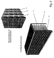
- 2 11 denotes the inlet chamber, 12 a filtration channel, and 13 the ash collecting area, in which, not shown, the discharge device can be implemented.
- structural elements of this document as they are also present in the particulate filter for passenger cars and / or those of the catalyst, can also be integrated here
- the installation direction can be selected independently, which also allows an inflow of the exhaust gas volume flow from above, which in turn benefits the ash accumulation, which is thus facilitated substantially by gravity. Shown is a filter with countercurrent. It has been shown that in this product case, the production method according to the patent EP 0627983 the most suitable one is.
- Non-Inventive Example 3 Catalyst
- FIG. 3 an exemplary example reduced in detail can be found here FIG. 3 be listed.
- 21 denotes a reinforced outer wall
- 22 the integration of voltage collecting and deflecting elements in the outer wall
- 23 denotes the integration of deflection elements for thermo-mechanical stresses in the channel structure.
- Other components can be easily integrated by the expert in this system and are also claimed.
- the system is being used for modular problem solving in the field of renewable energy generation for solar receivers, heat exchangers and wind power, as well as for use in liquid media such as gravity-driven power plants, geothermal energy plants or tidal power plants.
Landscapes
- Chemical & Material Sciences (AREA)
- Physics & Mathematics (AREA)
- Geometry (AREA)
- Chemical Kinetics & Catalysis (AREA)
- Engineering & Computer Science (AREA)
- General Engineering & Computer Science (AREA)
- Ceramic Engineering (AREA)
- Combustion & Propulsion (AREA)
- Mechanical Engineering (AREA)
- Materials Engineering (AREA)
- Organic Chemistry (AREA)
- Toxicology (AREA)
- Health & Medical Sciences (AREA)
- Thermal Sciences (AREA)
- Exhaust Gas After Treatment (AREA)
- Filtering Of Dispersed Particles In Gases (AREA)
- Physical Or Chemical Processes And Apparatus (AREA)
- Filtering Materials (AREA)
- Catalysts (AREA)
Description
- Die Erfindung betrifft eine von einem Fluid durchströmbare Vorrichtung mit einer zellulären Struktur, welche als solarer Receiver ausgebildet ist.
- Die Patentschrift
US 4,018,211 zeigt einen solaren Receiver mit einer Wabenstruktur, die fluidführende Kanäle bildet. - Gemäß vorliegender Erfindung soll die mechanische Stabilität einer zellulären Struktur, welche einen solaren Receiver bildet, erhöht werden.
- Während konventionelle zelluläre Strukturen die Fortpflanzung von Kraftfeldlinien, hervorgerufen durch mechanische und/oder durch thermische Spannungen, durch Zugspannungen, durch Druckspannungen, durch Biegespannungen oder durch Kombinationen derselben, ermöglichen, ist das erfindungsgemäße Konstruktionsmerkmal die Integration von spannungsaufteilenden und / oder spannungsumlenkenden Elementen in den Arbeitsbereich des Produktes, beispielsweise in die im Betrieb angeströmte Fläche, insbesondere die Filterfläche.
- Die Erfindung betrifft für mehr oder weniger rechteckige Zellstrukturen die Einfügung von innen hohlen Elementen in einzelnen oder mehreren Knotenpunkten der zellulären Strukturen, wobei der Innendurchmesser der Spannungsauffang- und Spannungsumlenkelemente meist größer gewählt ist als die der Wandstärke der Zellstruktur.
- Thermische und mechanische Spannungen bewirken an den Wandübergangostellen und / oder an Verbindungsstellen eine erhöhte Gefahr der Rissbildung hervorgerufen durch Spannungsspitzen. Erfindungsgemäß ist das Konstruktionsmerkmal die Zufügung von Spannungsspitzenverhinderungselementen in den Eckpunkten der Kontaktstellen in der Form, dass die Verbindungswinkel der Kanalwandungen, egal welchen Winkel sie zueinander einnehmen durch mehr oder weniger ausgeprägte Abrundungselemente ergänzt werden. Die Dimension und Biegung der Spannungsspitzenverhinderungselemente richtet sich dabei nach dem Maß der zu erwartenden Spannungen und dem verfügbaren Platz.
- Insbesondere aber nicht ausschließlich ist ein unterschiedliches Volumen- und / oder Querschnittsverhältnis der Zellen in einem Bauteil erforderlich. Eine beispielhafte Ausführungsform umfaßt Abstandselemente zwischen den einzelnen Kanälen des Bauteiles in der Form, dass am Beispiel von runden Kanälen mit gleichmäßiger Anordnung in Viererkombination, die ein fünftes Kanalelement bilden jeweils an gegenüberliegenden Kreissegmenten ein Verbindungselement beliebiger Länge eingesetzt wird. Je nach Länge dieses Verbindungselementes verändert sich dabei das Verhältnis der Größen der fünften Elemente. In der Ausführungsform der dreieckigen versetzten Anordnung der Strömungskanäle, bei denen drei Kanäle einen vierten Kanal umschließen wird analog jeweils ein Verbindungselement zwischen die Kanäle gesetzt. Je nach Länge dieses Verbindungselementes verändert sich dabei das Verhältnis der Größen des vierten Elementes. Analog ist die Konstruktion dahingehend zu verstehen, dass dieses Konstruktionselement auf alle anderen geometrischen Kanalformen angewendet werden kann,
- Nachstehend werden einige Problematiken der solaren Receiver und deren Konstruktionselemente beispielhaft und ohne Beschränkung der Allgemeinheit stellvertretend dargestellt und erfindungsgemäß in Anspruch genommen:
- In der solaren Energiegewinnung bestehen Problematiken bei den solaren Receivern für die als Solarthermiekraftwerke genannten Energiewandler. Ein Problemfeld ist der Strömungswiderstand der Receiver, der die Strömungsgeschwindigkeit der Wärmetauscherluft nachhaltig beeinflusst
- Ein weiteres Problemfeld ist die ungleichmäßige Aufheizung der Receiver als Einzelbauteil betrachtet
- Ein weiteres Problemfeld ist die monolithische gleichförmige Bauform der Strömungskanäle, die in sich lediglich einen begrenzten Energieübergang zwischen Receiver und Trägerluft ermöglichen
- Ein weiteres Problemfeld ist die Reaktionsträgheit der Receiver bei schnell wechselnden Einstrahlungsenergiekonzentrationen.
- In der Energiegewinnung von nicht unbeachtlicher Bedeutung ist die Problematik des Verlustes an Reaktionsfläche für den Energietransfer durch Montageflächen
- Ein letztes genanntes Problem, welches nicht als abschließend zu werten ist, ist die durch die Receiver hervorgerufene Gewichtsbelastung auf die Unterkonstruktion
- Die insbesondere für diese Problemfelder definierbaren Konstruktionselemente stellen sich erfindungsgemäß nachstehend dar, wobei die Aufstellung lediglich beispielhaft ist. Weitergehende Konstruktionselemente erkennt der Fachmann in den Prinzipien, die sich aus den Beispielen ergeben
- Das funktionelle Problem des zur Strömungserzeugung notwendigen Druckes kann ganz grundsätzlich durch das Konstruktionselement der verkürzten Länge der solaren Receiverkanäle entgegengewirkt werden. Bei der Erhöhung der Wandkontakte durch geeignete Elemente, welche zu erhöhtem Wärmeaustausch zwischen Receiverwandoberfläche und Trägerluft führen ist eine funktionelle Verkürzung der Receiverlänge auf Werte von unter 100 Millimeter möglich. Unter dem Aspekt der Wirtschaftlichkeit im Anlagenbau sind hier vorzugsweise Receiverbauteilhöhen von unterhalb 100 Millimeter, vorzugsweise unterhalb von 80 Millimeter idealerweise zu bevorzugen.
- Der Grundsatzproblematik der ungleichmäßigen Aufheizung der solaren Receiver über deren Querschnitt kann durch das Konstruktionselement dahingehend entgegengewirkt werden, dass experimentell und / oder rechnerisch ermittelte bereiche erhöhter Temperatur eine höhere Trägerluftdurchströmung zugeordnet wird als denen geringerer Temperaturen.
- Erreicht wird dies in dem Konstruktionselement durch eine Vergrößerung der Receiverkanalquerschnitte und / oder durch die Integration von Strömungskanalquerschnitten geringeren Strömungswiderstandes.
- Die dadurch bedingte Erhöhung der Durchströmungsgeschwindigkeit des Trägermediums bewirkt eine stärkere Abkühlung und führt so zu einem Temperaturausgleich. Besonders vorteilhaft ist dieses Konstruktionselement an Eckpunkten der Receiveroberfläche ausführbar. Dabei kann dieses Konstruktionselement über die ganze Receiverkanallänge ausgeführt werden, oder lediglich auf der Energieeinstrahlseite und / oder auf der Austragungsseite des Trägerstromes.
- Die Problematik der nach dem Stand der Technik monolithisch ausgeführten Receiverkanäle bewirkt durch die niedrigen Strömungsgeschwindigkeiten meistens nur einen nicht turbulenten Trägerluftstrom, der durch den gleichförmigen Volumenfluss eine geringe Wärmeübergangswirkung von Receiverkanaloberfläche zu Trägerluft aufweist.
- Diesem Problem kann durch ein Konstruktionselement dahingehend Rechnung getragen werden, dass in den Strömungsverlauf Abrisskanten eingebaut werden, die eine moderate Verwirbelung des Volumenstromes bewirken, ohne dabei selbst thermische Blockaden auszulösen. Eine exemplarische Ausführungsform ist dabei eine Verstärkung der Kanalwandungen nach der wärmeeintrittszone. Die auf die Verstärkung treffende Luftströmung stößt auf die Verbreiterung und wird dort verwirbelt. Die gleiche Wirkung ergibt sich, wenn das Konstruktionselement dahingehend ausgeführt wird, dass mehrere Absorberkanäle der Eintrittseite in einem Fortführungskanal münden. An der Übergangsstelle enden Kanalwandungen der Eintrittseite und bilden ebenfalls Abrisskanten und / oder Übergänge, die zu Verwirbelungen und damit besserem Wärmeübergang führen.
- Die Problematik der Receiverträgheit in Bezug auf die Absorptionsenergie bewirkt eine massive Beeinflussung des erreichbaren Temperaturgradienten in der Trägerluft. Je größer die Temperaturdifferenz der eingeleiteten Luft zur aufgeheizten Luft nach Receiverdurchtritt ist, umso geringer kann der Luftvolumenstrom bei gleicher Energietransportleistung gewählt werden, und / oder bei gleicher Volumenstromdimension die nutzbare Energietransformation entsprechend erhöht werden. Da die einleitenden Energiestrahlen nur wenige Millimeter direkt in die Receiveroberfläche eindringen ist das Konstruktionselement das der maximalen Absorptionsoberfläche bei geringstem Strömungswiderstand.
- Vorzugsweise, aber nicht ausschließlich wird dies durch die Konstruktion von mehr oder weniger runden Einlassöffnungen erreicht, denen optional durch die Oberflächengestaltung der Strömungskanäle zusätzliche Absorberflächen z.B. in der Form von Ausbuchtungen, Einbuchtungen, Stegsegmenten oder Zusatzsegmenten zugeordnet wird. Diese unter strömungs- und wärmeübergangsmäßig optimal konfigurierbare Absorberoberfläche kann zur Reduzierung des Strömungswiderstandes bereits nach wenigen Millimetern in einen strömungstechnisch optimalen Kanalquerschnitt überführt werden. Dabei ist es von erfindungsgemäßem Vorteil, wenn die Receiveroberfläche für die Energieaufnahme in den Receiver mit schnell reagierenden Materialkompositionen, z.B. durch geringe Dichte, durch Feinkörnigkeit, und / oder durch Porenvolumen und Größe direkt oder indirekt an einen tiefer liegenden Receiverteil angrenzen, der eine höhere Wärmspeicherkapazität aufweist und als ausgleichendes Receiverelement dient und dabei gleichzeitig stabilitätserhöhende Eigenschaften aufweist.
- Das Konstruktionsmerkmal für die Problematik der für die Energiegewinnung nicht zur Verfügung stehenden Reaktorfläche wird dahingehend gelöst, dass die einzelnen Receiver der Reaktionsfläche durch die Integration von spannungsabführenden oder spannungsumleitenden Teilsegmenten, so dass nach dem Stand der Technik mit mehreckigen Receiverzellen größer flächige Receiverelemente erreicht werden können, d.h. mit mindestens 100 cm2 Reaktionsfläche, vorzugsweise jedoch mit Reaktionsflächen der einzelnen solaren Receiver von mehr als 196 cm2. Dadurch wird die Reduzierung der Reaktionsfläche durch die Trägerkonstruktion nachhaltig verringert, so dass diese gewonnene Fläche für die Energiegewinnung verwendet werden kann.
- Das Konstruktionselement für die Problematik der Gewichtsbelastung der Reaktorflächenunterkonstruktion wird dahingehend gelöst, dass die für die solaren Receiver eingesetzten Materialien mit einer Porosierung versehen werden, welche die effektive Wärmeleitfähigkeit innerhalb des Receivermaterials nur unwesentlich beeinflusst. Zu diesem Zweck wird das Receivermaterial entweder aus porösen Metallen oder aus porösen Keramiken derart aufbereitet, dass die Kristallbestandteile innige Kontaktstellen aufweisen - und damit die erforderliche Festigkeit und Wärmeleitungsfähigkeit erlangen, ohne dass die Rohdichte des Receivermaterials hoch ist.
- Für eine technologische Optimierung der solaren Receiver hat sich das Konstruktionselement der multiplen Einzelelemente als möglich erwiesen. Mit diesem Element werden verschiedenartige Strömungsstrukturen und / oder Materialien und / oder Materialeigenschaften wie Dichte, Wärmeleitfähigkeit, Porosität und / oder verschiedener Heratellungstechniken aufeinandergepackt was zu einem Packet führt und entweder zu einem Bauteil fest zusammengefügt oder lediglich durch die Gehäuseeinfassung zusammengehalten oder gar nur durch das Eigengewicht aufeinandergedrückt werden , wobei der beim Betrieb entstehende Druck des Trägerluftstromes seinen Beitrag zum Zusammenhalt liefert. Dadurch ist es möglich auf die unterschiedlichsten thermomechanischen Zustände des solaren Receivers und den Zielanforderungen an die einzelnen Ebenen des Receivers gezielt einzugehen, ohne Material- und / oder Formeinschränkungen in Kauf nehmen zu müssen. So kann beispielhaft, und damit nicht ausschließlich, in der Eintrittszone des solaren Receivers ein Thermobooster aus hochtemperaturbeständigem keramischen Material mit geringer Wärmeformänderung, aber mit extrem hoher Absorberleistung eingesetzt werden, gefolgt von einem metallischem wärmeübertragungselement mit Kanalform, welcher von einer Schaummatrix abgeschlossen wird.
- Die Erfindung stellt eine von einem Fluid durchströmbare vorrichtung zur Verfügung welche als solarer Receiver ausgebildet ist und welche einen Arbeitsbereich mit einer zelluläre Struktur umfaßt, welche aus im wesentlichen rechteckigen Zellstrukturen aufgebaut ist, wobei der Arbeitsbereich neben den Wänden, welche zur Bildung der im wesentlichen rechteckigen Zellstrukturen mindestens erforderlich sind, als mindestens ein Versteifungselement zusätzliche Verstrebungen aufweist, welche durch die Einfügung von innen hohlen Elementen in einzelnen oder mehreren Knotenpunkten der zellulären Struktur gebildet sind und welche dazu geeignet sind, mechanische Spannungen aufzuteilen und/oder umzulenken.
- Die erfindungsgemäße Vorrichtung umfaßt Versteifungselemente in der zellulären Struktur. Die Vorrichtung weist dazu einen Bereich auf, welcher neben den Wänden, welche zur Bildung der zellulären Struktur mindestens erforderlich sind, zusätzliche Verstrebungen auf.
- In einer weiteren Ausführungsform der Erfindung umfaßt die Vorrichtung mindestens zwei Bereiche mit unterschiedlich großen Zellen in der jeweiligen zellulären Struktur.
- Die die zelluläre Struktur bildenden Elemente der Vorrichtung, insbesondere die Wände, sind in einer Ausführungsvariante der Erfindung porös und umfassen beispielsweise eine Keramik, insbesondere gesintertes Siliziumkarbid, und/oder zumindest ein Metall und/oder zumindest ein Glas.
- Bei einer Weiterbildung der Erfindung weist die Vorrichtung zumindest einen Kontaktstreifen und/oder Erhöhungen und/oder Erhöhung der Oberflächenrauhigkeit der Wandungen auf, so daß die Vorrichtung dazu geeignet ist, den Wandkontakt des Volumenstromes zu erhöhen.
- Durch die Integration von spannungsumlenkenden und/oder spannungsaufnehmenden Elementen in der Kanalstruktur kann die Vorrichtung eine Reaktionsfläche von mindestens 100 Zentimetern im Quadrat, vorzugsweise jedoch mehr als 196 Zentimetern im Quadrat aufweisen.
- In einer bevorzugten Ausführungsform der Erfindung weist die Vorrichtung zumindest einen Einlass- und zumindest einen Auslaßkanal auf. Vorteilhafterweise ist bei dieser Vorrichtung gemäß der Erfindung das Verhältnis der Querschnittsfläche des Einlaßkanals zur Querschnittsfläche des Auslaßkanals größer als 1 und liegt bevorzugt im Bereich von etwa 1,4 bis etwa 1,8, besonders bevorzugt bei etwa 1,6.
- Zur Herstellung einer von einem Fluid durchströmten Vorrichtung, wie sie zuvor beschrieben ist, steht ein Verfahren zur Verfügung, bei welchem eine von einem Fluid durchströmbare Vorrichtung mit einer zellulären Struktur geschaffen wird, wobei die die zelluläre Struktur aufbauenden Elemente, insbesondere die Wände der Vorrichtung, porös sind, wobei eine plastisch verformbare und anschließend verfestigbare Masse bereitgestellt wird und die folgenden beiden Schritte abwechselnd wiederholt, um schichtenweise eine bestimmte zelluläre Struktur aufzubauen:
- Erzeugen einer entsprechend der zellulären Struktur strukturierten Schicht aus der Masse,
- Verfestigen der Schicht,
- Zur Verdeutlichung der Systematik der Systemlösung über modulare Bauteile sind nachstehend einige exemplarische, und damit nicht ausschließliche, Ausführungsbeispiele für die Umsetzung der Erfindung aufgeführt.
Das System der modularen Problembehandlung über Komponenten kann im Rahmen eines Herstellungsverfahrens des dreidimensionalen Siebdruckes nach derEP 0627983 oder aber auch zum Drucken des Filterlementes über die, ebenfalls in dieser Patentschrift beschriebenen Methode des Düsendruckens angewendet werden. - Besonders geeignet zum Herstellen einer oben beschriebenen von einem Fluid durchströmbaren Vorrichtung mit einer zellulären Struktur oder eines oben beschriebenen Konstruktionselemente ist das folgende Verfahren.
- Dies betrifft ein Verfahren zum Herstellen einer von einem Fluid durchströmbaren Vorrichtung mit einer zellulären Struktur oder eines Konstruktionselements, insbesondere wie oben beschrieben, wobei die die zelluläre Struktur aufbauenden Elemente, insbesondere die Wände der Vorrichtung, porös sind, wobei eine plastisch verformbare und anschließend verfestigbare Masse bereitgestellt wird und die folgenden beiden Schritte abwechselnd wiederholt werden, um schichtenweise eine bestimmte zelluläre Struktur aufzubauen:
- Erzeugen einer entsprechend der zellulären Struktur strukturierten Schicht aus der Masse,
- Verfestigen der Schicht,
- Die Erfindung wird nachfolgend unter Bezugnahme auf die beigefügten Figuren anhand von weiteren Ausführungsbeispielen näher erläutert, wobei im Zusammenhang mit den die Erfindung betreffenden zellulären Strukturen diese auch im Zusammenhang mit von einem Fluid durchströmbaren Vorrichtungen beschreiben werden, die nicht als solarer Receiver ausgebildet sind.
- Es zeigen:
-
Figur 1 Eine schematische Darstellung einer zellulären Struktur für einen Dieselpartikelfilter im Querschnitt (links) und in einer vergrößerten Detailansicht (rechts), -
Figur 2 schematische Darstellungen von Elementkombinationen für einen Dieselpartikelfilter in einer weiteren Ausführungsform der Erfindung, -
Figur 3 eine schematische Darstellung einer zellulären Struktur für einen Katalysator im Querschnitt, und -
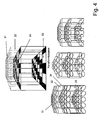
Figur 4 schematische Darstellungen zellulärer Strukturen für einen Solarthermiereceiver. - Exemplarisch, und damit nicht ausschließlich, sondern lediglich stellvertretend für andere aus der Schrift ableitbaren Lösungsprodukte, ist ein Ausführungsbeispiel für einen Dieselpartikelfilter für Personenkraftwagen in
Figur 1 dargestellt. Dabei bezeichnet 1 die verstärkte Außenwandung, 2 ein Spannungsauffangelement in der Außenwandung, 3 einen Einlasskanal, 4 einen Auslasskanal, 5 einen Kanalübergangssteg und 6 bezeichnet ein Abrundungselement. - Die Form der Übergänge zwischen Einlaß- und Auslaßkanälen sowie die Form der Spannungsauffangelemente kann im Rahmen der Erfindung ebenso wie die Außenmaße des Bauteils frei gewählt werden. Insbesondere kann, wie in
Figur 1 gezeigt, eine runde Formgebung, beispielsweise mit kreisbogenförmigen Übergängen beziehungsweise kreisförmigen Spannungsauffangelementen gewählt werden. Je nach Anwendungsfall kann die Formgebung der einzelnen Elemente, die ein Filtersegment, wie inFigur 1 dargestellt, umfassen, auch ungleichmäßig sein und/oder neben Kreisformen auch andere Formen wie beispielsweise Ellipsen, Schrägen, Vielecke und so weiter umfassen. - Zusätzlich oder alternativ zur Formgebung kann das Verhältnis des Querschnitts des Einlaßkanals 4 zum Querschntt des Auslaßkanals 5 größer als 1 und liegt bevorzugt im Bereich von etwa 1,4 bis etwa 1,8, besonders bevorzugt bei etwa 1,6 liegen.
- Nicht erfindungsgemäßes Beispiel 2; LKW Rußfilter Im wesentlichen stellen sich bei der Betrachtung der Partikelfiltration von Lastkraftwagen ähnliche Problematiken wie bei den Personenkraftwagen aus Beispiel 1 dar. Hier ist allerdings die Gewichtung vollkommen anders ausgerichtet, so dass die wesentlichsten Problematiken sich auf die Laufleistung der Antriebsaggregate beziehen, die im siebenstelligen Kilometer-Bereich liegen können. Auch ist der Anfall der Rußmenge besonders bei Lastfahrten wesentlich größer und schneller. Wendet man das System der modularen Problemlösung über Komponentenbausteine auf diesen Anwendungsfall hin an, so kommt man zu dem Ergebnis, dass für diese Art von Antriebsaggregaten in der Ausgestaltungsform der Einlasskammer mit integrierten Filterkanälen die sinnvollste und technologisch wirkungsvollste Filterelementform ist. Die in der Patentanmeldung
WO 2005/033477 beschriebene Beruhigungskammer stellt dabei keine Lösung der Austragungsproblematik für die Asche dar, da sich in dieser nicht nur Asche, sondern im wesentlichen Ruß ansammelt, der kaum von den regenerativen Bedingungen erreicht werden kann. In einer Ausgestaltungsform ist ein solcher erfindungsgemäßer Dieselpartikelfilter, der aus einem Teil, aber auch aus mehreren zusammengesetzten Teilen bestehen kann, zur Verdeutlichung in Figur II dargestellt. Es versteht sich, dass in der konstruktiven Gestaltung die Integration von Gradienten in der Teileanordnung und Lage, die Graduierung von Porositäten und , aber nicht ausschließlich die Strömungsrichtungen und anderes, leicht vom Fachmann nachvollziehen lassen können und in das Lösungssystem integriert werden können.
Dabei wird inFigur 2 mit 11 die Einlasskammer, mit 12 ein Filtrationskanal und mit 13 der Ascheansammlungsbereich bezeichnet bei dem, nicht dargestellt, die Austragungsvorrichtung implementiert werden kann. In dieser Ausführung ist es selbstverständlich, dass Konstruktionselemente dieser Schrift, wie sie auch bei dem Partikelfilter für Personenkraftwagen vorliegen und / oder denen des Katalysators, auch hier integriert werden können Besonders ist in diesem Beispiel hervorzuheben, dass die Einbaurichtung unabhängig gewählt werden kann, was auch eine Einströmung des Abgasvolumenstromes von oben her ermöglicht, was wiederum der Ascheansammlung zugute kommt, die damit wesentlich durch die Schwerkraft erleichtert wird. Dargestellt ist ein Filter mit Gegenstrom.
Es hat sich gezeigt, dass auch in diesem Produktfall, die Herstellungsmethode nach der PatentschriftEP 0627983 die geeignetste ist. - Nicht erfindungsgemäßes Beispiel 3: Katalysator Im Falle der Katalysatoren stellen sich die heutigen Problematiken weniger dramatisch dar und ein dringender Handlungsbedarf zur Verbesserung derselben besteht im Wesentlichen nur aus marketingrechtlicher Sicht, insbesondere als Abgrenzungsmerkmal im Verdrängungswettkampf, insbesondere in der Besetzung von Nischenmärkten. Insofern kann als eine beispielhafte und damit nicht ausschließliche Anwandungsausführung des Systems der modularen Problemlösung durch Komponentenelemente hier ein exemplarisches, um Einzelheiten reduziertes Beispiel in
Figur 3 aufgeführt werden. Dabei bezeichnet 21 eine verstärkte Außenwandung, 22 die Integration von Spannungsauffang- und umlenkelementen in der Außenwandung und 23 bezeichnet die Integration von Umlenkelementen für thermomechanische Spannungen in die Kanalstruktur. Weitere Komponentenelemente lassen sich vom Fachmann leicht in dieses System integrieren und werden ebenfalls beansprucht. - In der solarthermischen Energiegewinnung wir die gebündelte Lichtenergie auf die Oberfläche des Absorbers geleitet und von diesem aufgenommen. Dabei wird in Einstrahlungsrichtung Luft durch den Absorber gesaugt, welche sich durch die absorbierte Wärmeenergie der Lichtstrahlung aufheizt und im Anschluss entweder direkt verwendet wird, oder durch Wärmetauscherprozesse, z.B. Dampferzeugung, zur konventionellen Gewinnung elektrischer Energie verwendet wird. In dem exemplarisch ausgeführten Beispielen der
Figur 4 sind einige, und damit nicht ausschließliche, Möglichkeiten der solaren Receivergestaltung skizziert, wie sie aus der vorliegenden Schrift generiert und hergestellt werden können. Es ist für den Fachmann leicht nachvollziehbar, dass hier auch Konstruktionselemente der Partikelfilter, der Katalysatoren und anderer Anwendungen auf den solaren Receiver angewendet werden können, die erfindungsgemäß ebenfalls beansprucht werden. Dabei bezeichnet 31 die einleitende Oberfläche des solaren Receivers, 32 die Energieübertragungskanäle, 33 die Strömungskanäle und 34 bezeichnet die Strömungsabrisskante. - Das System wird zur modularen Problemlösung in dem Bereich der erneuerbaren Energiegewinnung für den solaren Receiver, dem Wärmetauscher und der Windkraftnutzung, aber auch bei dessen Verwendung in flüssigen Medien wie schwerkraftbetriebenen Energiegewinnungsanlagen, erdwärmebezogenen Energiegewinnungsanlagen oder gezeitenbetriebene Energiegewinnungsanlagen, in Anspruch genommen.
- Des weiteren wird das System zur modularen Problemlösung in dem Bereich der Fügtechnik, beispielhaft und damit nicht ausschließlich für die Gehäusekomponentenabdichtung, den Entkoppelungskomponenten und den Ausgleichskomponenten in Anlagenbauteilen und deren Verbindung, in Anspruch genommen.
- Allen Konstruktionselementen gemeinsam ist, dass diese am besten mit dem Herstellungsverfahren nach der Patentschrift
EP 0627983 ausgeführt werden können, Insbesondere der dreidimensionale Siebdruck erlaubt hier eine umfangreiche Abdeckung der Herstellungsmöglichkeit für die vorstehenden Produkte mit weitreichender Überlappung der Komponentenlösungen innerhalb eines Bauteiles. Es wird daher beansprucht, dass die Verwendung der Systemlösung anhand von Modulen nach dieser Schrift vorzugsweise aber nicht ausschließlich mittels dem Verfahren nach derEP 0627983 umgesetzt wird. Realisierbar ist die Umsetzung des Systems der modularen Lösung für zelluläre Produkte mit den Herstellungsverfahren des Strangpressens, des Foliengießens, des Folienziehens, des Schlickergießens, des Schäumens, des Düsendruckens und weiterer geeigneter Herstellungsverfahren, welche eine serientaugliche Umsetzung erlauben.
Claims (5)
- Von einem Fluid durchströmbare Vorrichtung, welche als solarer Receiver ausgebildet ist und welche einen Arbeitsbereich mit einer zellulären Struktur umfaßt, welche aus im wesentlichen rechteckigen Zellstrukturen aufgebaut ist,
wobei der Arbeitsbereich neben den Wänden, welche zur Bildung der im wesentlichen rechteckigen Zellstrukturen mindestens erforderlich sind, als mindestens ein Versteifungselement zusätzliche Verstrebungen aufweist,
welche durch die Einfügung von innen hohlen Elementen in einzelnen oder mehreren Knotenpunkten der zellulären Struktur gebildet sind, welche dazu geeignet sind, mechanische Spannungen aufzuteilen und/oder umzulenken. - Vorrichtung nach Anspruch 1 mit mindestens zwei Bereichen mit unterschiedlich großen Zellen in der jeweiligen zellulären Struktur.
- Vorrichtung nach einem der vorangegangenen Ansprüche wobei die die zelluläre Struktur bildenden Elemente, insbesondere die Wände, porös sind und beispielsweise eine Keramik, insbesondere gesintertes Siliziumkarbid, und/oder zumindest ein Metall und/oder zumindest ein Glas umfassen.
- Vorrichtung nach einem der vorangegangenen Ansprüche, dadurch gekennzeichnet, dass die Vorrichtung zumindest einen Kontaktstreifen und/oder Erhöhungen und/oder Erhöhung der Oberflächenrauhigkeit der wandungen aufweist, so daß die Vorrichtung dazu geeignet ist, den Wandkontakt des Volumenstromes zu erhöhen.
- Vorrichtung nach einem der vorstehenden Ansprüche,
dadurch gekennzeichnet, dass durch die Integration von spannungsumlenkenden und/oder spannungsaufnehmenden Elementen in der Kanalstruktur eine Reaktionsfläche von mindestens 100 Zentimetern im Quadrat, vorzugsweise jedoch mehr als 196 Zentimetern im Quadrat aufweist.
Applications Claiming Priority (2)
| Application Number | Priority Date | Filing Date | Title |
|---|---|---|---|
| DE200620007876 DE202006007876U1 (de) | 2006-05-15 | 2006-05-15 | Optimierung von zellulären Strukturen, insbesondere für die Abgasreinigung von Verbrennungsaggregaten und andere Anwendungsbereiche |
| PCT/EP2007/004259 WO2007131755A1 (de) | 2006-05-15 | 2007-05-14 | Optimierung von zellulären strukturen, insbesondere für die abgasreinigung von vebrennungsaggregaten und andere anwendungsbereiche |
Publications (2)
| Publication Number | Publication Date |
|---|---|
| EP2021594A1 EP2021594A1 (de) | 2009-02-11 |
| EP2021594B1 true EP2021594B1 (de) | 2012-10-03 |
Family
ID=38426476
Family Applications (1)
| Application Number | Title | Priority Date | Filing Date |
|---|---|---|---|
| EP20070725178 Active EP2021594B1 (de) | 2006-05-15 | 2007-05-14 | Von einem Fluid durchströmbare Vorrichtung, welche als solarer Receiver ausgebildet ist |
Country Status (7)
| Country | Link |
|---|---|
| US (1) | US20090308035A1 (de) |
| EP (1) | EP2021594B1 (de) |
| JP (1) | JP2009537722A (de) |
| CN (1) | CN101484669A (de) |
| DE (1) | DE202006007876U1 (de) |
| ES (1) | ES2394413T3 (de) |
| WO (1) | WO2007131755A1 (de) |
Families Citing this family (6)
| Publication number | Priority date | Publication date | Assignee | Title |
|---|---|---|---|---|
| JPWO2008126329A1 (ja) * | 2007-03-30 | 2010-07-22 | イビデン株式会社 | ハニカムフィルタ |
| JP2009270455A (ja) * | 2008-05-02 | 2009-11-19 | Nagamine Seisakusho:Kk | ハニカム構造体 |
| KR101112662B1 (ko) * | 2010-04-05 | 2012-02-15 | 주식회사 아모그린텍 | 대용량 금속 촉매 담체 및 이를 이용한 촉매 컨버터 |
| DE202013004745U1 (de) | 2013-05-23 | 2014-08-26 | Exentis-Knowledge Ag | Anlage zur Herstellung von dreidimensionalen Siebdrucken |
| CH711115A2 (de) * | 2015-05-22 | 2016-11-30 | Exentis Tech Ag | Mehrstufiger Körper mit einer Vielzahl von Strömungskanälen. |
| US10814266B2 (en) * | 2017-11-24 | 2020-10-27 | Ngk Insulators, Ltd. | Honeycomb filter |
Family Cites Families (42)
| Publication number | Priority date | Publication date | Assignee | Title |
|---|---|---|---|---|
| US3853485A (en) * | 1972-12-11 | 1974-12-10 | Corning Glass Works | Core member for catalytic oxidation converter |
| US4018211A (en) | 1974-05-01 | 1977-04-19 | Aai Corporation | Solar energy collection and transfer arrangement and method, and method of assembly |
| US4042738A (en) * | 1975-07-28 | 1977-08-16 | Corning Glass Works | Honeycomb structure with high thermal shock resistance |
| US4417908A (en) * | 1982-02-22 | 1983-11-29 | Corning Glass Works | Honeycomb filter and method of making it |
| US4420316A (en) * | 1982-02-22 | 1983-12-13 | Corning Glass Works | Filter apparatus and method of making it |
| US4428758A (en) * | 1982-02-22 | 1984-01-31 | Corning Glass Works | Solid particulate filters |
| US4416676A (en) * | 1982-02-22 | 1983-11-22 | Corning Glass Works | Honeycomb filter and method of making it |
| DE3235363A1 (de) * | 1982-09-24 | 1984-03-29 | Volkswagenwerk Ag, 3180 Wolfsburg | Keramikfilter, insbesondere fuer russ in der abgasstroemung einer brennkraftmaschine |
| JPH084749B2 (ja) * | 1985-01-21 | 1996-01-24 | 日本碍子株式会社 | セラミツクハニカム構造体 |
| JPH0634923B2 (ja) * | 1987-03-14 | 1994-05-11 | 日本碍子株式会社 | セラミツクハニカム構造体 |
| JPH0735730B2 (ja) * | 1987-03-31 | 1995-04-19 | 日本碍子株式会社 | 圧力波式過給機用排気ガス駆動セラミックローターとその製造方法 |
| DE3852937T2 (de) * | 1987-12-01 | 1995-09-07 | Asahi Glass Co Ltd | Abgasfilter. |
| US5013232A (en) * | 1989-08-24 | 1991-05-07 | General Motors Corporation | Extrusion die construction |
| DE4205969C2 (de) | 1992-02-27 | 1994-07-07 | Merck Patent Gmbh | Verfahren zur Herstellung von Formkörpern mit vorbestimmter Porenstruktur |
| NL9201923A (nl) * | 1992-11-04 | 1994-06-01 | Univ Delft Tech | Katalysator-orgaan, reactor voorzien van een dergelijk katalysator-orgaan, mal voor het vervaardigen van een dergelijk katalysator-orgaan, en werkwijze voor het hydrogenerend omzetten van een olie. |
| DE69800531T2 (de) * | 1997-04-09 | 2001-09-27 | Societe Des Ceramiques Techniques, Bazet | Makroporöser Träger mit einem Porositätsgradient und Methode zu dessen Herstellung |
| ATE236700T1 (de) * | 1998-07-07 | 2003-04-15 | Corning Inc | Dieselabgasfilter |
| DE19830342C1 (de) * | 1998-07-07 | 1999-11-25 | Siemens Ag | Katalysatorkörper |
| JP2002530175A (ja) * | 1998-11-20 | 2002-09-17 | コーニンクレッカ フィリップス エレクトロニクス エヌ ヴィ | コードレス走査ヘッドの充電器を備える超音波診断イメージングシステム |
| DE20023986U1 (de) * | 1999-09-29 | 2008-09-18 | IBIDEN CO., LTD., Ogaki-shi | Keramische Filteranordnung |
| US6673414B2 (en) * | 2000-12-20 | 2004-01-06 | Corning Incorporated | Diesel particulate filters |
| DE10240483A1 (de) * | 2002-09-03 | 2004-03-11 | EISENMANN Maschinenbau KG (Komplementär: Eisenmann-Stiftung) | Keramischer Wabenkörper zur Verwendung in einer thermischen Abgasbehandlungsvorrichtung |
| US7326270B2 (en) * | 2002-09-13 | 2008-02-05 | Ibiden Co., Ltd. | Filter |
| US7189375B2 (en) * | 2002-09-16 | 2007-03-13 | Delphi Technologies, Inc. | Exhaust treatment device |
| JP4437084B2 (ja) * | 2002-10-07 | 2010-03-24 | イビデン株式会社 | ハニカム構造体 |
| US7582270B2 (en) * | 2002-10-28 | 2009-09-01 | Geo2 Technologies, Inc. | Multi-functional substantially fibrous mullite filtration substrates and devices |
| US7574796B2 (en) * | 2002-10-28 | 2009-08-18 | Geo2 Technologies, Inc. | Nonwoven composites and related products and methods |
| JP4369141B2 (ja) * | 2003-02-18 | 2009-11-18 | 日本碍子株式会社 | ハニカムフィルタ及び排ガス浄化システム |
| KR100469066B1 (ko) * | 2003-04-14 | 2005-02-02 | 에스케이 주식회사 | 디젤차량 입자상 물질 제거용 필터 및 이의 제조방법 |
| DE602004011997T2 (de) * | 2003-06-05 | 2009-02-26 | Ibiden Co., Ltd., Ogaki | Wabenkörperstruktur |
| DE10343046A1 (de) | 2003-09-16 | 2005-05-12 | Deutsch Zentr Luft & Raumfahrt | Partikelfilter für einen Verbrennungsmotor |
| PL1676620T5 (pl) * | 2003-10-20 | 2012-10-31 | Ibiden Co Ltd | Struktura plastra miodu |
| US20070152364A1 (en) * | 2005-11-16 | 2007-07-05 | Bilal Zuberi | Process for extruding a porous substrate |
| KR100804933B1 (ko) * | 2004-05-06 | 2008-02-20 | 이비덴 가부시키가이샤 | 벌집형 구조체 및 그 제조 방법 |
| WO2005110578A1 (ja) * | 2004-05-18 | 2005-11-24 | Ibiden Co., Ltd. | ハニカム構造体及び排気ガス浄化装置 |
| DE202004013009U1 (de) * | 2004-08-18 | 2006-01-05 | Robert Bosch Gmbh | Reinigungseinsatz für Abgasreinigungsanlagen |
| DE102004027818A1 (de) * | 2004-06-08 | 2006-01-05 | Robert Bosch Gmbh | Filtereinrichtung für ein Abgassystem einer Brennkraftmaschine, sowie Verfahren zum Herstellen einer solchen Filtereinrichtung |
| FR2874647B1 (fr) * | 2004-08-25 | 2009-04-10 | Saint Gobain Ct Recherches | Bloc filtrant a ailettes pour la filtration de particules contenues dans les gaz d'echappement d'un moteur a combustion interne |
| JP4511396B2 (ja) * | 2005-03-22 | 2010-07-28 | 日本碍子株式会社 | ハニカム構造体及びその製造方法 |
| JP4805823B2 (ja) * | 2005-04-07 | 2011-11-02 | イビデン株式会社 | ハニカム構造体 |
| EP1957184A1 (de) * | 2005-12-05 | 2008-08-20 | Eidgenössische Materialprüfungs- und Forschungsanstalt Empa | Diffusor für abgasreinigungssysteme |
| JP2009154124A (ja) * | 2007-12-27 | 2009-07-16 | Ngk Insulators Ltd | 部分目封止レスdpf |
-
2006
- 2006-05-15 DE DE200620007876 patent/DE202006007876U1/de not_active Expired - Lifetime
-
2007
- 2007-05-14 US US12/300,576 patent/US20090308035A1/en not_active Abandoned
- 2007-05-14 WO PCT/EP2007/004259 patent/WO2007131755A1/de not_active Ceased
- 2007-05-14 EP EP20070725178 patent/EP2021594B1/de active Active
- 2007-05-14 JP JP2009510338A patent/JP2009537722A/ja active Pending
- 2007-05-14 ES ES07725178T patent/ES2394413T3/es active Active
- 2007-05-14 CN CNA2007800247676A patent/CN101484669A/zh active Pending
Also Published As
| Publication number | Publication date |
|---|---|
| ES2394413T3 (es) | 2013-01-31 |
| WO2007131755A1 (de) | 2007-11-22 |
| DE202006007876U1 (de) | 2007-09-20 |
| US20090308035A1 (en) | 2009-12-17 |
| EP2021594A1 (de) | 2009-02-11 |
| CN101484669A (zh) | 2009-07-15 |
| JP2009537722A (ja) | 2009-10-29 |
Similar Documents
| Publication | Publication Date | Title |
|---|---|---|
| EP3143357B1 (de) | Wärmeübertragungsvorrichtung und deren verwendung | |
| DE102009015849A1 (de) | Wärmetauscher | |
| DE20321503U1 (de) | Wabenstrukturkörper | |
| WO2012017041A2 (de) | Hochtemperatur-wärmespeicher für solarthermische kraftwerke | |
| EP0881447A2 (de) | Wärmeübertrager sowie Wärmeübertrageranordnung für ein Kraftfahrzeug | |
| WO2010086443A2 (de) | Solarabsorbermodul und solarabsorberanordnung | |
| DE60207120T3 (de) | Partikelfilterwabenstruktur mit Haupt- und Neben-Wabenstrukturen | |
| DE69505459T2 (de) | Honigwaben-Regenerator | |
| WO2011064109A1 (de) | Abgasreinigungskomponente mit umlenkfläche und verfahren zu deren herstellung | |
| EP2041800A2 (de) | Solarmodul | |
| EP2678615B1 (de) | Flachwärmetauscher | |
| EP1019617A1 (de) | Wabenkörperanordnung mit tragabschnitten | |
| WO2007131755A1 (de) | Optimierung von zellulären strukturen, insbesondere für die abgasreinigung von vebrennungsaggregaten und andere anwendungsbereiche | |
| EP3297759B1 (de) | Mehrstufiger körper mit einer vielzahl von strömungskanälen, herstellung und verwendung | |
| DE19807080A1 (de) | Geschichteter Wärmetauscher | |
| EP0843804B1 (de) | Speicherblock für regenerativ-wärmetauscher | |
| EP1753520B1 (de) | Reinigungseinsatz für abgasreinigungsanlagen, insbesondere für partikelfilter | |
| WO2002102492A1 (de) | Abgaspartikelfilter aus sintermetall | |
| DE102019207136A1 (de) | Kühler für eine Batterie, Verwendung von Kunststoffröhren in einem Kühler und Batterie mit zumindest einem Kühler | |
| DE102015101356A1 (de) | Roststab mit Kühlmittel-Kanal | |
| EP1525377B1 (de) | Abgasfilter mit mindestens einer filterlage und verfahren zur herstellung einer filterlage | |
| DE102020203157B4 (de) | Poröse keramikstruktur | |
| DE102005055955B3 (de) | Solarempfänger | |
| DE68905402T2 (de) | Waermeaustauscher zwischen einem gas und einer fluessigkeit mit erhoehten thermischen austauschfaehigkeiten. | |
| AT501042B1 (de) | Vorrichtung zum reinigen von kraftfahrzeugabgasen |
Legal Events
| Date | Code | Title | Description |
|---|---|---|---|
| PUAI | Public reference made under article 153(3) epc to a published international application that has entered the european phase |
Free format text: ORIGINAL CODE: 0009012 |
|
| AK | Designated contracting states |
Kind code of ref document: A1 Designated state(s): AT BE BG CH CY CZ DE DK EE ES FI FR GB GR HU IE IS IT LI LT LU LV MC MT NL PL PT RO SE SI SK TR |
|
| AX | Request for extension of the european patent |
Extension state: AL BA HR MK RS |
|
| 17P | Request for examination filed |
Effective date: 20081212 |
|
| 17Q | First examination report despatched |
Effective date: 20090508 |
|
| RIN1 | Information on inventor provided before grant (corrected) |
Inventor name: BAUER, ELKE Inventor name: KRYTS, OTTMAR Inventor name: BAUER, JOERG |
|
| RAP1 | Party data changed (applicant data changed or rights of an application transferred) |
Owner name: BAUER TECHNOLOGIES GMBH |
|
| RTI1 | Title (correction) |
Free format text: DEVICE SUITABLE FOR A FLUID THROUGH-FLOW FORMED AS A SOLAR RECEIVER |
|
| GRAP | Despatch of communication of intention to grant a patent |
Free format text: ORIGINAL CODE: EPIDOSNIGR1 |
|
| RAX | Requested extension states of the european patent have changed |
Extension state: HR Payment date: 20081212 |
|
| GRAS | Grant fee paid |
Free format text: ORIGINAL CODE: EPIDOSNIGR3 |
|
| GRAA | (expected) grant |
Free format text: ORIGINAL CODE: 0009210 |
|
| AK | Designated contracting states |
Kind code of ref document: B1 Designated state(s): AT BE BG CH CY CZ DE DK EE ES FI FR GB GR HU IE IS IT LI LT LU LV MC MT NL PL PT RO SE SI SK TR |
|
| AX | Request for extension of the european patent |
Extension state: HR |
|
| REG | Reference to a national code |
Ref country code: GB Ref legal event code: FG4D Free format text: NOT ENGLISH |
|
| REG | Reference to a national code |
Ref country code: AT Ref legal event code: REF Ref document number: 578086 Country of ref document: AT Kind code of ref document: T Effective date: 20121015 Ref country code: CH Ref legal event code: EP |
|
| REG | Reference to a national code |
Ref country code: IE Ref legal event code: FG4D Free format text: LANGUAGE OF EP DOCUMENT: GERMAN |
|
| REG | Reference to a national code |
Ref country code: DE Ref legal event code: R096 Ref document number: 502007010635 Country of ref document: DE Effective date: 20121129 |
|
| REG | Reference to a national code |
Ref country code: CH Ref legal event code: NV Representative=s name: BOVARD AG, CH |
|
| REG | Reference to a national code |
Ref country code: ES Ref legal event code: FG2A Ref document number: 2394413 Country of ref document: ES Kind code of ref document: T3 Effective date: 20130131 |
|
| PG25 | Lapsed in a contracting state [announced via postgrant information from national office to epo] |
Ref country code: SI Free format text: LAPSE BECAUSE OF FAILURE TO SUBMIT A TRANSLATION OF THE DESCRIPTION OR TO PAY THE FEE WITHIN THE PRESCRIBED TIME-LIMIT Effective date: 20121003 |
|
| REG | Reference to a national code |
Ref country code: NL Ref legal event code: VDEP Effective date: 20121003 |
|
| REG | Reference to a national code |
Ref country code: LT Ref legal event code: MG4D |
|
| PG25 | Lapsed in a contracting state [announced via postgrant information from national office to epo] |
Ref country code: FI Free format text: LAPSE BECAUSE OF FAILURE TO SUBMIT A TRANSLATION OF THE DESCRIPTION OR TO PAY THE FEE WITHIN THE PRESCRIBED TIME-LIMIT Effective date: 20121003 Ref country code: IS Free format text: LAPSE BECAUSE OF FAILURE TO SUBMIT A TRANSLATION OF THE DESCRIPTION OR TO PAY THE FEE WITHIN THE PRESCRIBED TIME-LIMIT Effective date: 20130203 Ref country code: SE Free format text: LAPSE BECAUSE OF FAILURE TO SUBMIT A TRANSLATION OF THE DESCRIPTION OR TO PAY THE FEE WITHIN THE PRESCRIBED TIME-LIMIT Effective date: 20121003 Ref country code: NL Free format text: LAPSE BECAUSE OF FAILURE TO SUBMIT A TRANSLATION OF THE DESCRIPTION OR TO PAY THE FEE WITHIN THE PRESCRIBED TIME-LIMIT Effective date: 20121003 Ref country code: LT Free format text: LAPSE BECAUSE OF FAILURE TO SUBMIT A TRANSLATION OF THE DESCRIPTION OR TO PAY THE FEE WITHIN THE PRESCRIBED TIME-LIMIT Effective date: 20121003 |
|
| PG25 | Lapsed in a contracting state [announced via postgrant information from national office to epo] |
Ref country code: LV Free format text: LAPSE BECAUSE OF FAILURE TO SUBMIT A TRANSLATION OF THE DESCRIPTION OR TO PAY THE FEE WITHIN THE PRESCRIBED TIME-LIMIT Effective date: 20121003 Ref country code: CY Free format text: LAPSE BECAUSE OF FAILURE TO SUBMIT A TRANSLATION OF THE DESCRIPTION OR TO PAY THE FEE WITHIN THE PRESCRIBED TIME-LIMIT Effective date: 20121003 Ref country code: PT Free format text: LAPSE BECAUSE OF FAILURE TO SUBMIT A TRANSLATION OF THE DESCRIPTION OR TO PAY THE FEE WITHIN THE PRESCRIBED TIME-LIMIT Effective date: 20130204 Ref country code: GR Free format text: LAPSE BECAUSE OF FAILURE TO SUBMIT A TRANSLATION OF THE DESCRIPTION OR TO PAY THE FEE WITHIN THE PRESCRIBED TIME-LIMIT Effective date: 20130104 Ref country code: PL Free format text: LAPSE BECAUSE OF FAILURE TO SUBMIT A TRANSLATION OF THE DESCRIPTION OR TO PAY THE FEE WITHIN THE PRESCRIBED TIME-LIMIT Effective date: 20121003 |
|
| PG25 | Lapsed in a contracting state [announced via postgrant information from national office to epo] |
Ref country code: DK Free format text: LAPSE BECAUSE OF FAILURE TO SUBMIT A TRANSLATION OF THE DESCRIPTION OR TO PAY THE FEE WITHIN THE PRESCRIBED TIME-LIMIT Effective date: 20121003 Ref country code: CZ Free format text: LAPSE BECAUSE OF FAILURE TO SUBMIT A TRANSLATION OF THE DESCRIPTION OR TO PAY THE FEE WITHIN THE PRESCRIBED TIME-LIMIT Effective date: 20121003 Ref country code: SK Free format text: LAPSE BECAUSE OF FAILURE TO SUBMIT A TRANSLATION OF THE DESCRIPTION OR TO PAY THE FEE WITHIN THE PRESCRIBED TIME-LIMIT Effective date: 20121003 Ref country code: BG Free format text: LAPSE BECAUSE OF FAILURE TO SUBMIT A TRANSLATION OF THE DESCRIPTION OR TO PAY THE FEE WITHIN THE PRESCRIBED TIME-LIMIT Effective date: 20130103 Ref country code: EE Free format text: LAPSE BECAUSE OF FAILURE TO SUBMIT A TRANSLATION OF THE DESCRIPTION OR TO PAY THE FEE WITHIN THE PRESCRIBED TIME-LIMIT Effective date: 20121003 |
|
| PLBE | No opposition filed within time limit |
Free format text: ORIGINAL CODE: 0009261 |
|
| STAA | Information on the status of an ep patent application or granted ep patent |
Free format text: STATUS: NO OPPOSITION FILED WITHIN TIME LIMIT |
|
| PG25 | Lapsed in a contracting state [announced via postgrant information from national office to epo] |
Ref country code: RO Free format text: LAPSE BECAUSE OF FAILURE TO SUBMIT A TRANSLATION OF THE DESCRIPTION OR TO PAY THE FEE WITHIN THE PRESCRIBED TIME-LIMIT Effective date: 20121003 Ref country code: IT Free format text: LAPSE BECAUSE OF FAILURE TO SUBMIT A TRANSLATION OF THE DESCRIPTION OR TO PAY THE FEE WITHIN THE PRESCRIBED TIME-LIMIT Effective date: 20121003 |
|
| 26N | No opposition filed |
Effective date: 20130704 |
|
| REG | Reference to a national code |
Ref country code: DE Ref legal event code: R097 Ref document number: 502007010635 Country of ref document: DE Effective date: 20130704 |
|
| BERE | Be: lapsed |
Owner name: BAUER TECHNOLOGIES G.M.B.H. Effective date: 20130531 |
|
| PG25 | Lapsed in a contracting state [announced via postgrant information from national office to epo] |
Ref country code: MC Free format text: LAPSE BECAUSE OF FAILURE TO SUBMIT A TRANSLATION OF THE DESCRIPTION OR TO PAY THE FEE WITHIN THE PRESCRIBED TIME-LIMIT Effective date: 20121003 |
|
| REG | Reference to a national code |
Ref country code: IE Ref legal event code: MM4A |
|
| PG25 | Lapsed in a contracting state [announced via postgrant information from national office to epo] |
Ref country code: BE Free format text: LAPSE BECAUSE OF NON-PAYMENT OF DUE FEES Effective date: 20130531 |
|
| PG25 | Lapsed in a contracting state [announced via postgrant information from national office to epo] |
Ref country code: IE Free format text: LAPSE BECAUSE OF NON-PAYMENT OF DUE FEES Effective date: 20130514 |
|
| PG25 | Lapsed in a contracting state [announced via postgrant information from national office to epo] |
Ref country code: MT Free format text: LAPSE BECAUSE OF FAILURE TO SUBMIT A TRANSLATION OF THE DESCRIPTION OR TO PAY THE FEE WITHIN THE PRESCRIBED TIME-LIMIT Effective date: 20121003 |
|
| PG25 | Lapsed in a contracting state [announced via postgrant information from national office to epo] |
Ref country code: TR Free format text: LAPSE BECAUSE OF FAILURE TO SUBMIT A TRANSLATION OF THE DESCRIPTION OR TO PAY THE FEE WITHIN THE PRESCRIBED TIME-LIMIT Effective date: 20121003 |
|
| PG25 | Lapsed in a contracting state [announced via postgrant information from national office to epo] |
Ref country code: LU Free format text: LAPSE BECAUSE OF NON-PAYMENT OF DUE FEES Effective date: 20130514 Ref country code: HU Free format text: LAPSE BECAUSE OF FAILURE TO SUBMIT A TRANSLATION OF THE DESCRIPTION OR TO PAY THE FEE WITHIN THE PRESCRIBED TIME-LIMIT; INVALID AB INITIO Effective date: 20070514 |
|
| REG | Reference to a national code |
Ref country code: FR Ref legal event code: PLFP Year of fee payment: 10 |
|
| REG | Reference to a national code |
Ref country code: FR Ref legal event code: PLFP Year of fee payment: 11 |
|
| REG | Reference to a national code |
Ref country code: FR Ref legal event code: PLFP Year of fee payment: 12 |
|
| REG | Reference to a national code |
Ref country code: DE Ref legal event code: R082 Ref document number: 502007010635 Country of ref document: DE Representative=s name: BLUMBACH ZINNGREBE PATENTANWAELTE PARTG MBB, DE Ref country code: DE Ref legal event code: R082 Ref document number: 502007010635 Country of ref document: DE Representative=s name: MANITZ FINSTERWALD PATENT- UND RECHTSANWALTSPA, DE Ref country code: DE Ref legal event code: R082 Ref document number: 502007010635 Country of ref document: DE Representative=s name: HENKEL & PARTNER MBB PATENTANWALTSKANZLEI, REC, DE Ref country code: DE Ref legal event code: R082 Ref document number: 502007010635 Country of ref document: DE Representative=s name: WENZEL NEMETZADE WARTHMUELLER PATENTANWAELTE P, DE Ref country code: DE Ref legal event code: R082 Ref document number: 502007010635 Country of ref document: DE Representative=s name: BLUMBACH ZINNGREBE PATENT- UND RECHTSANWAELTE , DE Ref country code: DE Ref legal event code: R081 Ref document number: 502007010635 Country of ref document: DE Owner name: EXENTIS KNOWLEDGE GMBH, CH Free format text: FORMER OWNER: BAUER TECHNOLOGIES GMBH, 56204 HILLSCHEID, DE |
|
| REG | Reference to a national code |
Ref country code: CH Ref legal event code: PUE Owner name: EXENTIS KNOWLEDGE GMBH, CH Free format text: FORMER OWNER: BAUER TECHNOLOGIES GMBH, DE |
|
| REG | Reference to a national code |
Ref country code: GB Ref legal event code: 732E Free format text: REGISTERED BETWEEN 20180927 AND 20181005 |
|
| REG | Reference to a national code |
Ref country code: FR Ref legal event code: CD Owner name: EXENTIS KNOWLEDGE GMBH, CH Effective date: 20181025 Ref country code: FR Ref legal event code: TP Owner name: EXENTIS KNOWLEDGE GMBH, CH Effective date: 20181025 |
|
| REG | Reference to a national code |
Ref country code: ES Ref legal event code: PC2A Owner name: EXENTIS KNOWLEDGE GMBH Effective date: 20190130 |
|
| REG | Reference to a national code |
Ref country code: AT Ref legal event code: PC Ref document number: 578086 Country of ref document: AT Kind code of ref document: T Owner name: EXENTIS KNOWLEDGE GMBH, CH Effective date: 20190304 |
|
| REG | Reference to a national code |
Ref country code: DE Ref legal event code: R082 Ref document number: 502007010635 Country of ref document: DE Representative=s name: MANITZ FINSTERWALD PATENT- UND RECHTSANWALTSPA, DE Ref country code: DE Ref legal event code: R082 Ref document number: 502007010635 Country of ref document: DE Representative=s name: HENKEL & PARTNER MBB PATENTANWALTSKANZLEI, REC, DE Ref country code: DE Ref legal event code: R082 Ref document number: 502007010635 Country of ref document: DE Representative=s name: WENZEL NEMETZADE WARTHMUELLER PATENTANWAELTE P, DE |
|
| REG | Reference to a national code |
Ref country code: DE Ref legal event code: R082 Ref document number: 502007010635 Country of ref document: DE Representative=s name: HENKEL & PARTNER MBB PATENTANWALTSKANZLEI, REC, DE Ref country code: DE Ref legal event code: R082 Ref document number: 502007010635 Country of ref document: DE Representative=s name: WENZEL NEMETZADE WARTHMUELLER PATENTANWAELTE P, DE |
|
| PGFP | Annual fee paid to national office [announced via postgrant information from national office to epo] |
Ref country code: AT Payment date: 20200515 Year of fee payment: 14 |
|
| REG | Reference to a national code |
Ref country code: DE Ref legal event code: R082 Ref document number: 502007010635 Country of ref document: DE Representative=s name: WENZEL NEMETZADE WARTHMUELLER PATENTANWAELTE P, DE |
|
| REG | Reference to a national code |
Ref country code: AT Ref legal event code: MM01 Ref document number: 578086 Country of ref document: AT Kind code of ref document: T Effective date: 20210514 |
|
| PG25 | Lapsed in a contracting state [announced via postgrant information from national office to epo] |
Ref country code: AT Free format text: LAPSE BECAUSE OF NON-PAYMENT OF DUE FEES Effective date: 20210514 |
|
| PGFP | Annual fee paid to national office [announced via postgrant information from national office to epo] |
Ref country code: DE Payment date: 20250519 Year of fee payment: 19 |
|
| PGFP | Annual fee paid to national office [announced via postgrant information from national office to epo] |
Ref country code: GB Payment date: 20250522 Year of fee payment: 19 Ref country code: ES Payment date: 20250616 Year of fee payment: 19 |
|
| PGFP | Annual fee paid to national office [announced via postgrant information from national office to epo] |
Ref country code: FR Payment date: 20250523 Year of fee payment: 19 |
|
| PGFP | Annual fee paid to national office [announced via postgrant information from national office to epo] |
Ref country code: CH Payment date: 20250601 Year of fee payment: 19 |
|
| REG | Reference to a national code |
Ref country code: CH Ref legal event code: S11 Free format text: ST27 STATUS EVENT CODE: U-0-0-S10-S11 (AS PROVIDED BY THE NATIONAL OFFICE) Effective date: 20260327 Ref country code: CH Ref legal event code: Y10 Free format text: ST27 STATUS EVENT CODE: U-0-0-Y10-Y00 (AS PROVIDED BY THE NATIONAL OFFICE) Effective date: 20260327 |