EP2021100B1 - Procédé pour préparer un mélange gazeux - Google Patents
Procédé pour préparer un mélange gazeux Download PDFInfo
- Publication number
- EP2021100B1 EP2021100B1 EP07725274.0A EP07725274A EP2021100B1 EP 2021100 B1 EP2021100 B1 EP 2021100B1 EP 07725274 A EP07725274 A EP 07725274A EP 2021100 B1 EP2021100 B1 EP 2021100B1
- Authority
- EP
- European Patent Office
- Prior art keywords
- reducing agent
- evaporator chamber
- evaporator
- aqueous solution
- line
- Prior art date
- Legal status (The legal status is an assumption and is not a legal conclusion. Google has not performed a legal analysis and makes no representation as to the accuracy of the status listed.)
- Expired - Fee Related
Links
- 0 C=*1*CCC1 Chemical compound C=*1*CCC1 0.000 description 1
Images


Classifications
-
- B—PERFORMING OPERATIONS; TRANSPORTING
- B01—PHYSICAL OR CHEMICAL PROCESSES OR APPARATUS IN GENERAL
- B01D—SEPARATION
- B01D53/00—Separation of gases or vapours; Recovering vapours of volatile solvents from gases; Chemical or biological purification of waste gases, e.g. engine exhaust gases, smoke, fumes, flue gases, aerosols
- B01D53/34—Chemical or biological purification of waste gases
- B01D53/74—General processes for purification of waste gases; Apparatus or devices specially adapted therefor
- B01D53/86—Catalytic processes
- B01D53/90—Injecting reactants
-
- B—PERFORMING OPERATIONS; TRANSPORTING
- B01—PHYSICAL OR CHEMICAL PROCESSES OR APPARATUS IN GENERAL
- B01D—SEPARATION
- B01D53/00—Separation of gases or vapours; Recovering vapours of volatile solvents from gases; Chemical or biological purification of waste gases, e.g. engine exhaust gases, smoke, fumes, flue gases, aerosols
- B01D53/34—Chemical or biological purification of waste gases
- B01D53/92—Chemical or biological purification of waste gases of engine exhaust gases
- B01D53/94—Chemical or biological purification of waste gases of engine exhaust gases by catalytic processes
- B01D53/9404—Removing only nitrogen compounds
- B01D53/9409—Nitrogen oxides
- B01D53/9431—Processes characterised by a specific device
-
- B—PERFORMING OPERATIONS; TRANSPORTING
- B01—PHYSICAL OR CHEMICAL PROCESSES OR APPARATUS IN GENERAL
- B01D—SEPARATION
- B01D53/00—Separation of gases or vapours; Recovering vapours of volatile solvents from gases; Chemical or biological purification of waste gases, e.g. engine exhaust gases, smoke, fumes, flue gases, aerosols
- B01D53/34—Chemical or biological purification of waste gases
- B01D53/92—Chemical or biological purification of waste gases of engine exhaust gases
- B01D53/94—Chemical or biological purification of waste gases of engine exhaust gases by catalytic processes
-
- C—CHEMISTRY; METALLURGY
- C01—INORGANIC CHEMISTRY
- C01C—AMMONIA; CYANOGEN; COMPOUNDS THEREOF
- C01C1/00—Ammonia; Compounds thereof
- C01C1/02—Preparation, purification or separation of ammonia
- C01C1/08—Preparation of ammonia from nitrogenous organic substances
-
- C—CHEMISTRY; METALLURGY
- C01—INORGANIC CHEMISTRY
- C01C—AMMONIA; CYANOGEN; COMPOUNDS THEREOF
- C01C1/00—Ammonia; Compounds thereof
- C01C1/02—Preparation, purification or separation of ammonia
- C01C1/08—Preparation of ammonia from nitrogenous organic substances
- C01C1/086—Preparation of ammonia from nitrogenous organic substances from urea
-
- F—MECHANICAL ENGINEERING; LIGHTING; HEATING; WEAPONS; BLASTING
- F01—MACHINES OR ENGINES IN GENERAL; ENGINE PLANTS IN GENERAL; STEAM ENGINES
- F01N—GAS-FLOW SILENCERS OR EXHAUST APPARATUS FOR MACHINES OR ENGINES IN GENERAL; GAS-FLOW SILENCERS OR EXHAUST APPARATUS FOR INTERNAL COMBUSTION ENGINES
- F01N3/00—Exhaust or silencing apparatus having means for purifying, rendering innocuous, or otherwise treating exhaust
- F01N3/08—Exhaust or silencing apparatus having means for purifying, rendering innocuous, or otherwise treating exhaust for rendering innocuous
- F01N3/10—Exhaust or silencing apparatus having means for purifying, rendering innocuous, or otherwise treating exhaust for rendering innocuous by thermal or catalytic conversion of noxious components of exhaust
- F01N3/18—Exhaust or silencing apparatus having means for purifying, rendering innocuous, or otherwise treating exhaust for rendering innocuous by thermal or catalytic conversion of noxious components of exhaust characterised by methods of operation; Control
- F01N3/20—Exhaust or silencing apparatus having means for purifying, rendering innocuous, or otherwise treating exhaust for rendering innocuous by thermal or catalytic conversion of noxious components of exhaust characterised by methods of operation; Control specially adapted for catalytic conversion ; Methods of operation or control of catalytic converters
- F01N3/2066—Selective catalytic reduction [SCR]
-
- F—MECHANICAL ENGINEERING; LIGHTING; HEATING; WEAPONS; BLASTING
- F01—MACHINES OR ENGINES IN GENERAL; ENGINE PLANTS IN GENERAL; STEAM ENGINES
- F01N—GAS-FLOW SILENCERS OR EXHAUST APPARATUS FOR MACHINES OR ENGINES IN GENERAL; GAS-FLOW SILENCERS OR EXHAUST APPARATUS FOR INTERNAL COMBUSTION ENGINES
- F01N2240/00—Combination or association of two or more different exhaust treating devices, or of at least one such device with an auxiliary device, not covered by indexing codes F01N2230/00 or F01N2250/00, one of the devices being
- F01N2240/20—Combination or association of two or more different exhaust treating devices, or of at least one such device with an auxiliary device, not covered by indexing codes F01N2230/00 or F01N2250/00, one of the devices being a flow director or deflector
-
- F—MECHANICAL ENGINEERING; LIGHTING; HEATING; WEAPONS; BLASTING
- F01—MACHINES OR ENGINES IN GENERAL; ENGINE PLANTS IN GENERAL; STEAM ENGINES
- F01N—GAS-FLOW SILENCERS OR EXHAUST APPARATUS FOR MACHINES OR ENGINES IN GENERAL; GAS-FLOW SILENCERS OR EXHAUST APPARATUS FOR INTERNAL COMBUSTION ENGINES
- F01N2240/00—Combination or association of two or more different exhaust treating devices, or of at least one such device with an auxiliary device, not covered by indexing codes F01N2230/00 or F01N2250/00, one of the devices being
- F01N2240/40—Combination or association of two or more different exhaust treating devices, or of at least one such device with an auxiliary device, not covered by indexing codes F01N2230/00 or F01N2250/00, one of the devices being a hydrolysis catalyst
-
- F—MECHANICAL ENGINEERING; LIGHTING; HEATING; WEAPONS; BLASTING
- F01—MACHINES OR ENGINES IN GENERAL; ENGINE PLANTS IN GENERAL; STEAM ENGINES
- F01N—GAS-FLOW SILENCERS OR EXHAUST APPARATUS FOR MACHINES OR ENGINES IN GENERAL; GAS-FLOW SILENCERS OR EXHAUST APPARATUS FOR INTERNAL COMBUSTION ENGINES
- F01N2610/00—Adding substances to exhaust gases
- F01N2610/02—Adding substances to exhaust gases the substance being ammonia or urea
-
- F—MECHANICAL ENGINEERING; LIGHTING; HEATING; WEAPONS; BLASTING
- F01—MACHINES OR ENGINES IN GENERAL; ENGINE PLANTS IN GENERAL; STEAM ENGINES
- F01N—GAS-FLOW SILENCERS OR EXHAUST APPARATUS FOR MACHINES OR ENGINES IN GENERAL; GAS-FLOW SILENCERS OR EXHAUST APPARATUS FOR INTERNAL COMBUSTION ENGINES
- F01N2610/00—Adding substances to exhaust gases
- F01N2610/06—Adding substances to exhaust gases the substance being in the gaseous form
-
- F—MECHANICAL ENGINEERING; LIGHTING; HEATING; WEAPONS; BLASTING
- F01—MACHINES OR ENGINES IN GENERAL; ENGINE PLANTS IN GENERAL; STEAM ENGINES
- F01N—GAS-FLOW SILENCERS OR EXHAUST APPARATUS FOR MACHINES OR ENGINES IN GENERAL; GAS-FLOW SILENCERS OR EXHAUST APPARATUS FOR INTERNAL COMBUSTION ENGINES
- F01N2610/00—Adding substances to exhaust gases
- F01N2610/10—Adding substances to exhaust gases the substance being heated, e.g. by heating tank or supply line of the added substance
-
- F—MECHANICAL ENGINEERING; LIGHTING; HEATING; WEAPONS; BLASTING
- F01—MACHINES OR ENGINES IN GENERAL; ENGINE PLANTS IN GENERAL; STEAM ENGINES
- F01N—GAS-FLOW SILENCERS OR EXHAUST APPARATUS FOR MACHINES OR ENGINES IN GENERAL; GAS-FLOW SILENCERS OR EXHAUST APPARATUS FOR INTERNAL COMBUSTION ENGINES
- F01N2610/00—Adding substances to exhaust gases
- F01N2610/11—Adding substances to exhaust gases the substance or part of the dosing system being cooled
-
- Y—GENERAL TAGGING OF NEW TECHNOLOGICAL DEVELOPMENTS; GENERAL TAGGING OF CROSS-SECTIONAL TECHNOLOGIES SPANNING OVER SEVERAL SECTIONS OF THE IPC; TECHNICAL SUBJECTS COVERED BY FORMER USPC CROSS-REFERENCE ART COLLECTIONS [XRACs] AND DIGESTS
- Y02—TECHNOLOGIES OR APPLICATIONS FOR MITIGATION OR ADAPTATION AGAINST CLIMATE CHANGE
- Y02T—CLIMATE CHANGE MITIGATION TECHNOLOGIES RELATED TO TRANSPORTATION
- Y02T10/00—Road transport of goods or passengers
- Y02T10/10—Internal combustion engine [ICE] based vehicles
- Y02T10/12—Improving ICE efficiencies
Definitions
- the present invention can be used to provide reducing agents in the selective catalytic reduction of nitrogen oxides in the exhaust system of internal combustion engines.
- the exhaust of internal combustion engines has substances whose emission into the environment is undesirable.
- nitrogen oxides (NO x ) may only be contained in the exhaust gas of internal combustion engines up to a certain limit value.
- the emission of nitrogen oxides, aftertreatment methods have been established with which a further reduction of nitrogen oxide emissions is possible.
- SCR selective catalytic reduction
- a selective reduction of the nitrogen oxides to molecular nitrogen (N 2 ) takes place with the use of a selectively acting reducing agent.
- One possible reducing agent is ammonia (NH 3 ).
- Ammonia is often not stored in the form of ammonia, but rather an ammonia precursor is stored, which is converted into ammonia if necessary.
- Possible ammonia precursors are, for example, urea ((NH 2 ) 2 CO), ammonium carbamate, isoceranoic acid (HCNO), cyanuric acid and the like.
- urea has proven to be easy to store. Preference is given to storing urea in the form of a urea-water solution. Urea and in particular urea-water solution is harmless to health, easy to distribute and store. Such a urea-water solution is marketed under the name "AdBlue”.
- the heater can be designed with a plate or with a microwave generator:
- a method in which a urea-water solution upstream of a hydrolysis catalyst is metered into a partial flow of an exhaust gas of an internal combustion engine.
- a hydro- and thermolysis of the urea to ammonia takes place, which is used in a downstream SCR catalyst as a reducing agent.
- the process described here has the disadvantage that the hydrolysis catalyst is cooled by the evaporation of the urea-water solution.
- the hydrolysis catalyst is cooled by the evaporation of the urea-water solution.
- it can come at least in areas of the hydrolysis to such a strong cooling that here the hydrolysis reaction no longer or no longer completely runs.
- damage to the hydrolysis catalyst and, in particular, detachment of a catalytically active coating may occur.
- the object of the present invention is to propose a method with which the disadvantages known from the prior art can at least be alleviated.
- a reservoir for an aqueous solution comprising at least one reducing agent precursor, which can be brought into fluid communication with an evaporator chamber. Furthermore, a means for dosing the aqueous solution is formed in the evaporator chamber.
- the device is characterized in that means for heating the evaporator chamber are formed, with which the evaporator chamber can be heated to a temperature greater than or equal to a critical temperature at which the aqueous solution evaporates at least partially.
- the evaporator chamber is part of an evaporator unit.
- the evaporator unit has means for separating droplets formed within a feed line or in the evaporator chamber.
- the means is connected to the metering line through which steam passes.
- In the means one or more baffles are formed, which force the steam flow to deflections.
- the one or more baffles and / or a housing of the agent are heated, in particular so that deposited drops are also evaporated.
- the aqueous solution comprises urea as a reducing agent precursor and the gaseous mixture comprises ammonia and / or urea.
- a corresponding aqueous solution is sold under the brand name "AdBlue”.
- the aqueous solution may comprise further substances which serve, for example, to lower the melting point of the solution.
- the aqueous solution may comprise formic acid and / or ammonium formate.
- a corresponding aqueous solution is sold under the trade name "Denoxium”.
- a fluidic connection between the reservoir and the evaporator chamber is understood in particular to mean that a fluid can flow from the reservoir to the evaporator chamber.
- you can Reservoir and evaporator chamber may be connected by a delivery line through which the aqueous solution can flow during operation.
- the critical temperature is chosen so that a complete evaporation of the aqueous solution takes place.
- a reducing agent precursor is understood in particular to mean a substance which can split off or be converted into the reducing agent.
- the means for dosing the aqueous solution in the evaporator chamber is in particular designed so that the metering is done in Eintropen single drops or a jet of droplets in the evaporator chamber.
- the dosing means comprises in particular a correspondingly formed nozzle.
- a catalyst is understood in particular as a catalyst carrier body which is provided with a corresponding catalytically active coating.
- a hydrolysis catalyst refers to a catalyst carrier body provided with a coating that catalyzes hydrolysis of the reducing agent precursor.
- An SCR catalyst refers to a catalyst carrier body provided with a catalytically active coating for catalyzing the selective catalytic reduction of nitrogen oxides.
- the device can be advantageously avoided by using the device that the latter is substantially cooled upon impact of the reducing agent precursor on the hydrolysis, since this does not have to muster the evaporation enthalpy of the aqueous solution.
- the harmful consequences of local cooling of the hydrolysis catalyst can be avoided.
- it can thus be ensured that even with relatively large amounts of reducing agent precursor or aqueous solution which meets the hydrolysis catalyst, the cooling of the hydrolysis catalyst does not take place so strongly that the hydrolysis proceeds only incompletely.
- the evaporator chamber comprises a substantially closed volume which has only a first opening for connection of a delivery line for the aqueous solution and a second opening for connection of a metering line for discharging the gaseous substance mixture.
- the evaporation chamber comprises a substantially closed volume, which has only a first opening for connection of a delivery line for the aqueous solution, a second opening for connection of a metering line for discharging the gaseous substance mixture and a third opening for the addition of exhaust gas.
- aqueous solution can be brought into the evaporator chamber through the delivery line and that the gaseous substance mixture is removed from the evaporator chamber through the addition line and fed to an exhaust system, in particular upstream of a hydrolysis catalytic converter.
- an exhaust system in particular upstream of a hydrolysis catalytic converter.
- a closed volume means that this is not just a catalyst carrier body, which is heated, for example, but that here a further component is formed, which largely is completed.
- the cross sections of the first and the second opening together are preferably at most 10% of the surface of the evaporator chamber.
- the means for heating the evaporator chamber comprise at least one of the following components: a) an electrical resistance heater and b) a burner for burning a fuel.
- the electrical resistance heater comprises a heating wire, which is in thermal contact with the evaporator chamber.
- the evaporator chamber is wrapped with the heating wire or this is introduced into the wall of the evaporator chamber.
- the electrical resistance heating is particularly preferred because it can be controlled in a simple manner and is very dynamically controllable in particular with a corresponding configuration of the evaporator chamber with regard to the choice of material and thickness of the material. This means that very quickly the output of gaseous substance mixture can be adapted to the demand for reducing agent in the exhaust system of an internal combustion engine.
- the means for heating the evaporator chamber may comprise a Peltier element and / or utilize the waste heat from other components.
- a Peltier element is understood to mean, in particular, an electrical component which, when current flows through, generates a temperature difference which is based on the so-called Peltier effect.
- a Peltier element comprises one or more elements of p- and n-doped semiconductor material, which are alternately interconnected via electrically conductive material. The sign of the temperature difference is dependent on the direction of the current flow, so that both a cooling and a heating with a Peltier element can be realized.
- a fuel is understood in particular hydrocarbons and / or hydrogen. Hydrocarbons can be taken from the corresponding tank of the internal combustion engine.
- the evaporator chamber is substantially spherically symmetric.
- a vaporizer chamber volume which is heated as uniformly as possible is preferred because it avoids the formation of regions of lower temperature, since droplets often form in these regions from condensed reducing agent precursor, which possibly precipitates in the interior of the vaporizer chamber or is discharged through the admixing line into the exhaust system.
- An essentially spherically symmetrical evaporator chamber advantageously permits the most uniform possible temperature control within the evaporator chamber.
- the evaporator chamber has a radius of 2 mm to 10 mm
- radii proposed here have proven to be particularly advantageous, since a relatively low power input, for example, an electrical resistance heating a fast, reliable and flexible dynamic control of the output of the gaseous mixture could be achieved.
- radii of 2 mm and more are possible and according to the invention.
- a radius of 3 to 4 mm has proven particularly advantageous.
- the corresponding radius can be adapted to the maximum amount of reducing agent required or to the maximum amount of aqueous solution to be evaporated, so that, for example, for use in a passenger car, a radius of 2 to 35 mm is advantageous, while for use in trucks a radius of 50 to 150 mm is advantageous.
- the evaporator chamber has a volume of 30 to 4000 mm 3 .
- the volume of the evaporator chamber is chosen in particular so that even at maximum load conditions of the internal combustion engine, a sufficiently large amount of the gaseous substance mixture can be provided, so that sufficient reducing agent for selective catalytic reduction (SCR, selective catalytic reduction) is available.
- SCR selective catalytic reduction
- the evaporator chamber volume in the exhaust system of passenger cars is up to 150 ml, preferably from about 100 mm 3 to 500 mm 3 .
- the volume of the evaporator chamber is preferably in the range of up to 750 ml.
- the means for heating the evaporator chamber can apply a heating power of up to 5000 W (watts).
- heating powers have been found to be particularly advantageous, since peaks of the demand for reducing agent can also be achieved by corresponding provision of a corresponding volume of the vaporous substance mixture with these heating powers.
- a heating power of up to 500 W has been found to be advantageous for trucks, this heating power is preferably in the range of up to 1500 W.
- a delivery line for conveying the aqueous solution is formed in the evaporator chamber, which connects the evaporator chamber with a reservoir and it is further a conveying means, by means of which a fluid can be conveyed through the delivery line.
- this may be a pump.
- the control of the entering into the evaporator chamber amount of aqueous solution can be done by regulating the pump and / or a corresponding valve.
- the device is designed so that in operation the temperature of the evaporator chamber is at most 25 ° C above and below a mean temperature.
- a temperature of the evaporator chamber is understood in particular a temperature of the wall of the evaporator chamber.
- An accurate temperature of the evaporator chamber has been found in experiments to be particularly essential, since a very uniform temperature control of a precipitate of reducing agent or by-products can be effectively avoided or at least limited. It has been found that even a relatively small deviation from the average - critical - temperature is sufficient to bring undesirable substances to precipitate.
- the design of the device comprises in particular a corresponding design of the means for heating the evaporator chamber. This is especially designed so that a very uniform energy input into the evaporator chamber.
- the evaporator chamber may advantageously be surrounded by a heating conductor. Also by a selection of an appropriate material can be achieved in an advantageous manner, a very uniform temperature of the evaporator chamber.
- the evaporator chamber has, at least in partial areas, means for increasing the wettability of the surface.
- This may in particular be a corresponding structuring of the surface of the evaporator chamber, which may include, for example, macroscopic structures or a corresponding coating.
- the evaporator chamber may comprise, at least in some areas, a hydrolysis catalyst coating which catalyzes the hydrolysis, in particular of urea to ammonia.
- An aqueous solution of at least one reducing agent precursor is conveyed into an evaporator chamber, wherein the evaporator chamber is heated so that the aqueous solution evaporates completely to the gaseous substance mixture.
- the heating of the evaporator chamber is carried out so that in addition to evaporation of the reducing agent precursor in aqueous solution, an at least partially thermolytic decomposition of the reducing agent precursor to a reducing agent.
- the method according to the invention can preferably be carried out in the device.
- a complete evaporation means in particular an evaporation of at least 90% by weight of the aqueous solution, preferably of 95% by weight, more preferably of at least 98% by weight.
- the promotion of the aqueous solution in the evaporator chamber is preferably carried out in droplet form, in particular in the form of individual drops and / or in the form of a droplet jet.
- the promotion can be made by a suitably trained and controllable nozzle.
- the evaporator chamber comprises a substantially closed volume, which has only a first opening for connection of a delivery line for the aqueous solution and a second opening for connection of a metering line for discharging the gaseous substance mixture.
- the evaporator chamber comprises a substantially closed volume, which has only a first opening for connection of a delivery line for the aqueous solution, a second port for connecting a metering line for discharging the gaseous mixture and a third port for the addition of exhaust gas ,
- the process control in the form that a substantially closed evaporator volume is used to evaporate the aqueous solution advantageously makes it possible to carry out a process in which, with a relatively low use of energy, a relatively high vapor yield of the aqueous solution can be achieved.
- the process control is designed so that the heating and evaporation of the aqueous solution take place through the walls of the substantially closed evaporator volume.
- the evaporator chamber is not filled with the liquid aqueous solution, but only drops of the aqueous solution are metered or injected.
- a nozzle may be formed, which injects the aqueous solution into the evaporator volume.
- the evaporator chamber is heated by an electrical resistance heater.
- further means for heating the evaporator chamber can be used.
- this may be the waste heat of other components or an additional burner, which is operated with fuel and which heats the evaporator chamber.
- at least one Peltier element can be used to control the temperature of the evaporator chamber.
- a temperature control is understood in particular to mean heating or cooling.
- the temperature control of the evaporator chamber is controlled.
- a control loop may be formed which determines the temperature at or in the evaporator chamber by means of at least one thermocouple and accordingly carries out a control.
- Other temperature sensors may be designed, from the values of which can be calculated back to the temperature in the evaporator chamber.
- mathematical models can be used, which were formed by the corresponding system.
- other elements can be integrated into this control loop alternatively or additionally.
- the temperature of a downstream hydrolysis catalyst can likewise be subjected to a regulation.
- the evaporator chamber is heated to an average temperature of 350 to 450 ° C, preferably about 370 to 390 ° C, in particular about 380 ° C.
- These temperatures advantageously allow evaporation of 90% by weight of the aqueous solution and more, preferably 95% by weight and more, more preferably 98% by weight or more.
- the evaporator chamber is heated to an average temperature which does not deviate at any point in the evaporator chamber by more than + 25 ° C or -25 ° C.
- the temperature or the average temperature of the evaporator chamber is understood to be the temperature at the outer or inner surface of the evaporator chamber.
- the inventive very precise control of the temperature of the evaporator chamber which allows a range of fluctuation of only a maximum of +/- 5 ° C to an average temperature, advantageously allows a process control in which the probability that the reducing agent, the reducing agent precursor or even at an undesirable side reaction resulting product on the surface of the evaporator chamber precipitates, is very low.
- experiments have shown that even very small deviations from the average temperature in individual areas of the evaporator chamber lead to precipitation of substances. Therefore, a very precise temperature control and regulation of advantage.
- the details and advantages disclosed for the device can be transferred and applied to the method according to the invention.
- the details and advantages disclosed for the method according to the invention can be transferred and applied to the device.
- the device 1 comprises a metering line 2 with discharge opening 3. Furthermore, means 4 for heating the metering line 2 are formed, with which the metering line 2 can be heated above a first critical temperature which is greater than the boiling point of water.
- the device 1 further comprises a reservoir, not shown here yet, which can be brought into fluidic connection with the metering line 2. Ie. in particular, that a fluid stored in the reservoir, such as, for example, an aqueous solution comprising at least one reducing agent precursor, can flow through the metering line 2 towards the discharge opening 3 during operation.
- a gaseous mixture of substances can be provided, which contains at least one reducing agent and / or at least one reducing agent precursor.
- the means 4 for heating the metering line 2 are coiled together with this spiral. Characterized a flowing through the metering line 2 fluid is heated and finally evaporated. As a result, a gaseous substance mixture which contains at least at least one reducing agent precursor is dispensed through the discharge opening 3.
- a gaseous substance mixture which contains at least at least one reducing agent precursor is dispensed through the discharge opening 3.
- the temperature of the means 4 for heating the metering line 2 can even take place at least partially thermolysis of the reducing agent precursor in the metering line 2, so that the discharged through the discharge opening gaseous mixture in addition to a reducing agent precursor such as urea already contains reducing agent such as ammonia ,
- the device 1 for providing a gaseous substance mixture also comprises a measuring sensor 5 with which the temperature can be measured at at least one point of the metering line 2.
- the sensor 5 may be, for example, a conventional thermocouple or a conventional thermoresistor.
- the device 1 and / or the individual components which require an electrical connection preferably comprise a cable tail for the realization of the electrical connections. Under a cable tail is understood in particular a cable connection, which is at least half a meter, preferably at least one meter long. This allows the formation of plug contacts in areas that are exposed to particularly low levels of environmental impact such as splashing water, rockfall or the like, especially in automobiles.
- Fig. 2 shows the device 1 from Fig. 1 on average.
- the feed line 2 through which the aqueous solution comprising at least one reducing agent precursor can flow during operation, and the means 4 for heating the metering line 2 can clearly be seen.
- the metering line 2 can have a constant cross section, but this can also be variable as in the present example ,
- the flow-through cross-section of the metering line 2 is, however, preferably between 0.75 mm 2 and 20 mm 2 , preferably the flow-through cross section is in the range of about 3 mm 2 .
- Fig. 2 also shows the sensor 5 for determining the temperature of the metering line 2.
- the means 4 are operated for heating the metering line 2 so that during operation, the temperature over the length of the metering line 2 at most 5 ° C above and below a mean temperature.
- the mean temperature corresponds essentially to the first critical temperature.
- the metering line 2 is formed in particular of a copper alloy.
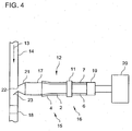
- Fig. 3 schematically shows the delivery line 6, via which the metering line 2 is connected in operation with a reservoir not shown here.
- the delivery line 6 has means 7 for tempering.
- the means 7 for tempering comprise in this embodiment in each case a plurality of Peltier elements 8 and a heat sink 9.
- the Peltier elements 8 are each provided with electrical connections 10, via which they can be supplied with power. Depending on the polarity of the current while the Peltier elements 8 are used for heating or cooling, so that with them a basic temperature of the delivery line 6 can be achieved.
- the heat sink 9 is used in particular for radiating heat energy when the feed line 6 is cooled by the Peltier element (s) 8.
- connection unit 11 is formed at least partially of a material having a thermal conductivity of less than 10 W / m K (watts per meter and Kelvin).
- the connection unit 11 is formed in particular from a ceramic material and / or polytetrafluoroethylene (PTFE).
- PTFE polytetrafluoroethylene
- the evaporator unit 12 and / or the metering line 2 has a significantly higher temperature than the delivery line 6.
- the evaporator unit a temperature of 300 ° C or more, 400 ° C or more or 420 ° C or have more and so to a substantially complete evaporation the aqueous solution within the evaporator unit 12, while the delivery line 6 only has a temperature level of 70 ° C or more, 80 ° C or more, or 90 ° C or more, to ensure that the aqueous solution is not yet in the delivery line 6 evaporated.
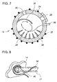
- Fig. 4 schematically shows a device 15 for the treatment of the exhaust gas 13 of an internal combustion engine, not shown.
- the exhaust gas 13 of the internal combustion engine flows through an exhaust pipe 14.
- the internal combustion engine processing apparatus 13 comprises a reducing agent solution evaporator 16, a hydrolysis catalyst 17, and an SCR catalyst 18.
- an aqueous solution comprising a reducing agent precursor is evaporated.
- urea is used as the reducing agent precursor.
- the reducing agent solution evaporator 16 in this exemplary embodiment comprises an evaporator unit 12 comprising a metering line 2 which is heated by means 4 for heating the metering line 2 and is connected to a delivery line 6 via a connecting unit 11.
- the delivery line 6 is surrounded by means 7 for controlling the temperature of the delivery line 6, which may comprise, for example, as shown above, one or more Peltier elements 8 and / or a heat sink 9.
- the aqueous solution of at least one reducing agent precursor can be conveyed from a corresponding reservoir 20 into the conveying line 6.
- a gas is provided which comprises at least one reducing agent precursor such as, for example, urea and possibly also ammonia already formed from the thermolysis of urea. This gaseous substance mixture is introduced into the hydrolysis catalyst 17 formed downstream of the reducing agent solution evaporator 16.
- the hydrolysis catalyst 17 is designed such that in particular urea is hydrolyzed to ammonia by a corresponding catalytically active coating applied to it. Generally, the hydrolysis catalyst 17 serves to hydrolyze a reducing agent precursor to a reducing agent.
- the gas leaving the hydrolysis catalyst 17, which contains a reducing agent and as a reducing agent mixture is designated is added via a metering 21 in the exhaust pipe 14.
- the metering line 21 opens into a metering opening in the exhaust pipe 14, which is upstream of the SCR catalyst 18. Downstream of the metering opening 22 and upstream of the SCR catalyst 18 mixing means 23 are formed in the form of a guide plate, which cause a mixing of the reducing agent mixture with the exhaust gas 13.
- the SCR catalyst reaches a mixture of reducing agent and exhaust gas, which leads to a reduction of the nitrogen oxides contained in the exhaust gas 13 in the SCR catalyst 18.
- an amount of reducing agent mixture is preferably provided such that as complete a conversion of the nitrogen oxides in the exhaust gas 13 in the SCR catalytic converter 18 can take place.
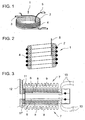
- Fig. 5 schematically shows a further embodiment of an evaporator unit 12.
- the evaporator unit 12 includes an evaporator chamber 24 that includes a substantially closed volume.
- the evaporator chamber 24 has only a first opening 25 for connecting a delivery line 6, not shown here, for conveying the aqueous solution, and a second opening 26 for connecting a metering line 2, not shown here, for discharging the gaseous substance mixture.
- a nozzle 62 is formed as a means for metering the aqueous solution 45 into the evaporator chamber 24. With this nozzle 62, the aqueous solution 45 is metered into the evaporator chamber 24.
- the evaporator unit 12 additionally has means for heating the evaporator chamber 24.
- These means are formed in the present embodiment by corresponding heating element 27, which are in contact with the evaporator chamber 24.
- this heating conductor 27 may be formed asymmetrically, ie in the areas which are substantially opposite the first opening 25, a greater density of heating conductors per unit area is formed than in the areas which are not substantially opposite the first opening 25.
- these funds include here cumulatively a means 63 for burning hydrocarbons such as a burner. Such a burner may also be suitable for carrying out a flame-free combustion of hydrocarbons.
- the evaporator chamber 24 is preferably made of a material comprising at least one of the following materials: a) copper; b) aluminum; c) stainless steel; d) nickel base material and e) chromium-nickel steel.
- the volume of the evaporator chamber 24 is preferably 1.5 to 10 cm 3 .
- an embodiment of the evaporator chamber 24 is preferably at least partially made of aluminum.
- the heating conductor 27 is preferably operated at a heating power that is up to about one kilowatt per second, the maximum heating power being determined depending on the application.
- the maximum heating power is in passenger cars preferably at about 500 to 700 W / s, in trucks at about 1200 to 1500 W / s.
- the heat capacity of the evaporator chamber 24 is preferably less than 120 J / K, more preferably 100 to 110 J / K.
- the first opening 25 and the second opening 26 preferably include an angle of 30 to 70 °.
- the aqueous solution 45 is preferably conveyed into the evaporator chamber 24 at up to 150 ml / min, preferably at up to 100 ml / min, more preferably at up to 30 ml / min.
- the evaporator chamber 24 in the region of the second opening 26 means, with which penetration of drops into the second opening 26 can be avoided.
- these are means by means of which a gas film lying between the drop and the wall of the evaporator chamber 24 can be broken through.
- these are projections of the walls or the like.
- the structures 28 may also be formed in this area.
- These structures 28 are drawn relatively large in the present embodiment, but it can also be a structured Surface acting, for example, by applying a corresponding coating on the inner surface of the evaporator chamber 24 can be achieved.
- these structures 28 may also comprise macroscopic structures having a structural amplitude of a few millimeters or even more. In general, these structures 28 are to be understood as means for increasing the wettability of the surface of the evaporator chamber 24.
- Fig. 6 schematically shows the first embodiment of the evaporator chamber 24 following an exhaust pipe 14.
- the evaporator chamber 24 is provided with a sheath 29.
- This jacket 29 is preferably formed from a corresponding thermal insulator which reduces heat losses to the environment.
- the means 27 for heating the evaporator chamber 24 can be connected via Schuleiteran Why 30 with a power source, not shown.
- the evaporator unit 12 is connected to a hydrolysis catalytic converter 17.
- the hydrolysis catalytic converter 17 has means 31 for controlling the temperature of the hydrolysis catalytic converter 17, which in the present embodiment consist of a corresponding heating wire with which the hydrolysis catalytic converter 17 is wound.
- To the hydrolysis catalyst 17 around a corresponding sheath 32 is formed, which is in particular a thermal insulation of the hydrolysis 17 relative to the environment to minimize occurring heat losses as possible.
- the hydrolysis catalyst is connected directly to the exhaust pipe 14 by protruding into this.
- a corresponding bore is formed in the exhaust gas line 14, into which the hydrolysis catalytic converter 17 or its jacket 32 can be introduced as tightly as possible.
- a baffle 34 is formed as passive mixing means, by means of which the hydrolysis catalyst 17 leaving reducing agent mixture 35 is mixed with the exhaust gas flowing in the exhaust pipe 14.
- a gaseous mixture of an aqueous solution containing urea as a reducing agent precursor is produced by the evaporator unit 12.
- the gaseous mixture formed in the evaporator unit 12 contains at least urea and possibly also already ammonia, which has been formed by thermolysis of the corresponding urea.
- This substance mixture is conducted via the second opening 26 into the hydrolysis catalytic converter 17, in which a substantially complete hydrolysis of the urea to ammonia takes place.
- a reducing agent mixture 35 which comprises ammonia is formed in the hydrolysis catalyst.
- a methodology is preferred in which 98% or more of the urea is ultimately converted to ammonia.
- Fig. 7 schematically shows an alternative embodiment of the evaporator unit of the FIGS. 5 and 6 ,
- the latter additionally has a third opening 36.
- exhaust gas can be introduced into the evaporator chamber 24 continuously or pulsately during operation.
- a better distribution of the urea in the resulting gas can be achieved compared to the first embodiment.
- such an evaporator unit 12 can also be used for the evaporation of solid urea, since water is introduced into the evaporator chamber 24 through the introduced through the third opening 36 exhaust gases of the internal combustion engine, which can be used later in the hydrolysis catalyst 17 for the hydrolysis of urea to ammonia.
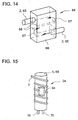
- Fig. 8 schematically shows the mouth of a metering 21 in the exhaust pipe 14 as part of a corresponding addition unit 46.
- the metering 21 is surrounded by a heating element 38, which is also formed around the mouth of the metering 21 into the exhaust pipe 14 around.
- Fig. 9 schematically shows a further possibility of a device 1 for providing a gaseous mixture comprising a reducing agent in a first intersection.
- the device 1 comprises a metering line 2, which is wrapped with a corresponding means 4 for the view of the metering line 2 or wound together with this.
- the metering line 2 and the means 4 for heating the metering line 2 are formed together in a casing 29.
- a first temperature sensor 39 is formed within the winding of the metering line 2.
- This first temperature sensor 39 can be connected via a first connecting element 40 to a corresponding control unit, not shown here.
- the evaporator unit 12 is connected to a hydrolysis catalyst 17.
- the hydrolysis catalyst 17 has a coating which catalyzes the hydrolysis of urea to ammonia.
- the hydrolysis catalytic converter 17 is surrounded by means 31 for controlling the temperature of the hydrolysis catalytic converter, which comprise a correspondingly formed heating wire.
- These means 31 for controlling the temperature of the hydrolysis catalytic converter 17 can be electrically conductively connected by corresponding first heating conductor connections 41 to a corresponding power supply. The same applies to the means 4 for heating the metering line 2, which can be provided via corresponding second Schuleiteran say 42 with a corresponding power supply.
- the hydrolysis catalytic converter 17 has a second temperature sensor 43, which can be connected via a corresponding second connecting element 44 to a control unit, not shown. By means of the second temperature sensor 43, the temperature within or on the hydrolysis catalyst 17 can be determined.
- an aqueous urea solution 45 is conveyed into the metering line 2.
- the corresponding gaseous mixture is added to the hydrolysis catalyst 17, which undergoes hydrolysis, preferably substantially complete hydrolysis of the urea comprising ammonia.
- the hydrolysis catalyst 17 leaves a corresponding reducing agent mixture 35, which can be introduced into an exhaust gas line 14 of the exhaust system of an internal combustion engine.
- Fig. 10 schematically shows an apparatus 1 for providing a gaseous substance mixture 35 comprising at least one reducing agent.
- This comprises sequentially a delivery line 6, by means of which an aqueous solution from a reservoir, not shown, is conveyed into an evaporator unit 12.
- the evaporator unit 12 is adjoined by a hydrolysis catalytic converter 17 and to this a metering line 21 for adding the corresponding substance mixture to an exhaust line 14 (not shown) or an addition unit 46 for adding the reducing agent mixture to the exhaust gas line 14.
- the evaporator unit 12 has a third temperature sensor 47. With this third temperature sensor 47, the temperature of or in the delivery line 6 can be measured.
- the metering line 21 and / or the adding unit 46 has a fourth temperature measuring sensor 48, with which the temperature of the metering line 21 and / or the adding unit 46 or the temperature in the metering line 21 and / or the adding unit 46 can be determined.
- the evaporator unit 12 has means 4 for heating the metering line 2 and / or means 27 for heating the evaporator chamber 24.
- the hydrolysis catalytic converter 17 may optionally or as an alternative and / or as an additive to the means 4, 27 have means 31 for controlling the temperature of the hydrolysis catalytic converter 17.
- the delivery line 6 comprises temperature control means 49, by means of which the delivery line 6 can be tempered.
- Peltier elements are possible here, advantageously and according to the invention.
- the dosing line 21 and / or the adding unit 46 have addition temperature control means 50, by means of which the dosing line 21 and / or the adding unit 46 can be tempered.
- the use of at least one Peltier element is advantageous.
- Fig. 11 schematically shows a section of a device for providing a gaseous mixture of substances.
- a honeycomb body 52 is formed in front of an SCR catalyst 18 with channels through which a fluid can flow, which is part of a corresponding mixing agent 53.
- the honeycomb body 52 is formed such that the exhaust gas can flow through it at least partially at an angle to the main flow direction of the exhaust gas.
- the main flow direction 54 is indicated by a corresponding arrow in Fig. 11 indicated.
- the honeycomb body 52 is conical.
- the honeycomb body has a larger recess 55, which is free of channels. In this recess 55, the metering 21 opens as part of the addition unit 46 through which the reducing agent mixture 35 is entered during operation.
- Fig. 12 schematically shows an example of an addition unit 46 with a metering 21 for adding the reducing agent mixture in an exhaust pipe 14.
- the metering 21 penetrates the wall of the exhaust pipe 14 in a curved state.
- the metering line 21 has perforations 56 in the region which projects into the exhaust gas line 14.
- the curvature or the curved entry of the metering 21 into the exhaust pipe 14 is not mandatory, just as well could the dosing 21 also occur perpendicular or straight into the exhaust pipe 14.
- a baffle 23 is formed, which leads to a further improved mixing of the reducing agent mixture with the exhaust gas 13 in the exhaust pipe 14.
- Fig. 13 schematically shows an embodiment of the device 1 for the treatment of an exhaust gas of an internal combustion engine, not shown.
- a first exhaust line 58 in this case the evaporation unit 12 and the hydrolysis catalyst 17 are formed.
- a distribution of the exhaust gas to the first 58 and a second exhaust line 59 is achieved.
- the SCR catalytic converter 18 is formed downstream of the junction 61 of the first exhaust gas line 58 into the second exhaust gas line 59.
- the evaporator unit 12 has means 64 for the separation of drops, which may be formed, for example, within the metering line 2 or into or after the second opening 26 of the evaporator chamber 24.
- Fig. 14 shows an embodiment of such means 64 for depositing drops.
- This means 64 is connected to the metering line 2 or generally a conduit 65 through which steam passes. If there are still drops in the vapor, they are deposited in the present example by inertia effect.
- one or more baffles 66 are formed, which force the flow to deflections 67. Baffle plate 66 and / or the housing 68 of the means 64 are heated, so that deposited drops are also evaporated.
- the droplet deposition means 64 shown here other measures may alternatively or cumulatively be taken, for example
- the metering line 2 or the line 65 may have partially narrowed cross sections, projections, deflections or the like.
- Fig. 15 schematically shows a further embodiment of an evaporator unit 12, in which a metering line 2 by means 4 for heating the metering line 2 can be heated.
- the means 4 for heating the metering line 2 comprise. here a rod-shaped heating element 69, which is connectable via electrical connections 70 to a power source.
- a means 64 for the separation of drops is formed, which is heated via the contact to the rod-shaped heating element 69.
- Fig. 16 schematically shows a further embodiment of an evaporator unit 12, in which the metering line 2 is wound in the form of a loop twice around the rod-shaped heating element 69.
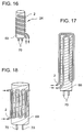
- FIGS. 17 and 18 show embodiments of evaporator units 12, in which the metering line 2 is not wound around the longitudinal axis of the rod-shaped heating element 69 but is secured in loops on the rod-shaped heating element 69.
- a cohesive connection between the metering line 2 and the rod-shaped heating element 69 is preferred, in particular a brazed connection.
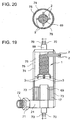
- FIGS. 19 and 20 schematically show a further embodiment of a device 1 for providing a gaseous substance mixture comprising at least one of the following substances: a) a reducing agent, preferably ammonia, and b) at least one reducing agent precursor, in particular urea with a hydrolysis catalyst 17.
- the device 1 comprises at least one metering line 2 , In the present embodiment, four Zugabe Oberen 2, which are spirally wound around a rod-shaped heating element 69.
- Each of the metering lines 2 has in each case a discharge opening 3, through which a gaseous mixture of substances is emitted during operation, which comprises a reducing agent.
- the discharge openings 3 are each distributed so as to be substantially evenly distributed on a circle.
- the metering lines 2 are connected to a reservoir 20, not shown here, from which an aqueous solution 45 of at least one reducing agent precursor is conveyed into the metering line 2 by means of a conveying means 19.
- Addition lines 2 and heating element 69 are part of a corresponding reducing agent solution evaporator 16.
- a hydrolysis catalytic converter 17 Downstream of the discharge openings 3, a hydrolysis catalytic converter 17 is formed, which can likewise be heated by a rod-shaped heating element 69. In an advantageous development, only a rod-shaped heating element 69 is formed, which is in thermal contact with both the or the metering lines 2 and with the hydrolysis catalyst 17.
- the Hydrolysekatlysator 17 is designed in the present embodiment as an annular honeycomb body. Downstream of the hydrolysis catalytic converter 17 is followed by a metering line 21, via which, during operation, the gas stream comprising at least one reducing agent can be guided into the exhaust gas line 14. About the connecting means 71, a mechanical connection to the exhaust pipe 14 can be produced.
- a thermal insulation 72 is formed, by means of which the hydrolysis catalytic converter 17 is thermally decoupled from the exhaust gas line 14. Furthermore, a heat shield 73 is formed, by means of which the hydrolysis catalytic converter 17 is protected against a radiation of heat. Furthermore, an air gap insulation 74 between an outer housing 75 and an inner housing 76 is formed, which also serves the thermal insulation.
- Fig. 20 shows a cross section through in the region of the metering lines 2, which can be seen around the rod-shaped heating element 69.
- Fig. 21 schematically shows a further embodiment of an apparatus 15 for the treatment of exhaust gas 13.
- a valve 77 is formed, which for dosing the aqueous solution 45 in the evaporator unit 12 is used.
- the valve 77 can be actuated via a control connection 78.
- Fig. 22 schematically shows a mouth portion 79 of an adding unit 46 in the exhaust pipe 14.
- the exhaust pipe 14 and / or the addition unit here has a diaphragm 80, which creates a dead or reassurance zone of the exhaust gas flow and thus a region of reduced pressure during operation in the mouth region 79 and thus ensures that no exhaust gas is pressed into the addition unit 46.
- the addition unit 46 further comprises a temperature sensor 81 comprising an annularly formed thermoresistor. Should deposits form in this area, the temperature sensor 81 may be connected to a power source (not shown) so as to increase the temperature to a second setpoint temperature, For example, from 550 ° C or more, preferably from 600 ° C or more cause a dissolution or reduction of deposits.
- Fig. 23 schematically shows a cross section of a honeycomb body 82, which can be used both as a hydrolysis 17 and as an SCR catalyst 18, wherein in this case other catalytically active coatings must be applied.
- the honeycomb body 82 is made up of smooth metallic layers 83 and corrugated metallic layers 84, which in this embodiment have been stacked into three stacks and then wound together.
- the honeycomb body 82 further comprises a jacket tube 85, which closes the honeycomb body 82 to the outside. Smooth 83 and corrugated layers 84 form channels 86, which can be flowed through for exhaust gas 13.
- Fig. 24 shows a further example of a honeycomb body 87 which is annular and can be used both as a hydrolysis catalyst 17 and as an SCR catalyst 18, wherein in this case other catalytically active coatings must be applied.
- the honeycomb body 87 is formed of layers 88 having smooth 89 and corrugated portions 90 folded together and channels 86, which can be flowed through for exhaust gas 13
- the honeycomb body 87 is closed by an outer jacket tube 91 and an inner jacket tube 92.
- hydrolysis 17 is in principle also provided with a the hydrolysis of urea to ammonia catalyzing coating provided pipe or a jacket tube with at least one inside the outer circumference attached structured metallic layer, which preferably has a freely flow-through cross-section radially in its interior, at least 20 % of the total cross-section of the jacket tube.
- These embodiments are preferably heated from the outside.
- the evaporator unit 12 If the temperature of the SCR catalytic converter 18 is above a predefinable limit, which is in particular the start-up temperature ("light off" temperature) of the SCR catalytic converter 18, the evaporator unit 12 is charged with the aqueous solution 45. If the evaporation unit 12, the metering line 2 and / or the evaporator chamber 24 are still essentially at their operating temperature, the above-mentioned diagnostic steps can be omitted.
- a predefinable limit which is in particular the start-up temperature ("light off" temperature) of the SCR catalytic converter 18
- the evaporator unit 12 If the temperature of the SCR catalytic converter 18 is above a predefinable limit, which is in particular the start-up temperature ("light off" temperature) of the SCR catalytic converter 18, the evaporator unit 12 is charged with the aqueous solution 45. If the evaporation unit 12, the metering line 2 and / or the evaporator chamber 24
- the heating power introduced into the evaporator unit 12 is correlated with the flow rate of aqueous solution 45. In particular, this means that it is checked what is required for a desired heating power for the evaporation of the respective flow rate. If the measured actual heating power is below the desired heating power for a period of time, then a warning is output to the user, since then a reduction of the cross section of the metering line 2 and / or the metering line 21 can be present.
- a return promotion of the aqueous solution 45 can be made from the metering line 2.
- the promotion of aqueous solution 45 are set, but still the evaporator unit 12, the metering line 2 and / or the evaporator chamber 24 is heated to the usual temperature, so as to perform a complete evaporation and thus to prevent the return conveyor also possible impurities in the evaporator unit 12, the metering line 2 and / or the evaporator chamber 24 in the delivery line 6 arrive.
- the return conveyance can then be initiated by the conveying means 19.
- a valve is formed on the connecting unit 11 or adjacent to this, by means of which air can be sucked in the return conveyance. is. In principle, it is conveyed back until the delivery line 6 is substantially emptied into the reservoir 20.
- delivery line 6, evaporator unit 12, metering line 2, evaporator chamber 24 and / or hydrolysis catalyst 17 may be formed in thermal contact, for example, to the fuel tank of the internal combustion engine. This usually has for reasons of frost protection to a heater, which can then also offer frost protection for the above components.
- an aqueous solution 45 comprising at least one reducing agent precursor is vaporisable.
- the SCR catalyst 18 is formed in the exhaust pipe 14, and the reducing agent solution evaporator 16 and the hydrolysis catalyst 17 are formed outside the exhaust pipe 14 and connectable thereto.
- the hydrolysis catalyst preferably comprises a jacket tube, wherein the jacket tube is not taken into account in determining the above-mentioned heat capacity.
- At least one at least partially structured metallic layer is preferably formed in the jacket tube.
- a free region without formation of at least partially structured layers is provided in the inner region, which comprises at least 20 or even 50 area% of the cross-sectional area of the jacket tube.
- the hydrolysis catalyst 17 advantageously has a cell density of less than 600 cpsi (cells per square inch), preferably of 400 cpsi and less, more preferably of 300, 200 or 100 cpsi and less.
- the hydrolysis catalyst 17 is mechanically connected to the exhaust pipe 14.
- the hydrolysis catalytic converter 17 is preferably thermally decoupled from the exhaust gas line 14.
- the honeycomb body 52 has passages through which fluid can flow and openings which connect adjacent channels to one another.
- a thermal insulation 72 is formed downstream of the hydrolysis catalytic converter 17. This thermal insulation 72 is preferably formed immediately after the hydrolysis catalytic converter 17.
- this temperature sensor can be connected to a power supply, so that it can also be used for heating the corresponding component a) to g).
- a conveying means 19 is formed, by means of which the aqueous solution 45 can be conveyed from a reservoir to the evaporator unit 24.
- the conveying means 19 preferably comprises at least one pump, preferably a metering pump.
- the pump can build up a delivery pressure which is greater than the highest possible exhaust gas pressure during operation of the internal combustion engine at the addition unit 46 and / or the dosing line 21.
- at least one valve for metering the aqueous solution 45 is formed between the conveying means 19 and the evaporator unit 12.
- step b) the reducing agent mixture 35 is mixed with at least parts of the exhaust gas 14.
- this process can be further developed in that, in step a), an evaporation of an aqueous solution 45 comprising at least one reducing agent precursor takes place in an evaporator unit 12. Furthermore, it is preferred that step b) takes place at least partially in a hydrolysis catalytic converter 17.
- a further embodiment of this method comprises the delivery of the aqueous solution 45 through a delivery line 6 to the reducing agent solution evaporator 16.
- the aqueous solution 45 can be recirculated through the delivery line 6.
- up to 2.5 ml of the aqueous solution 45 are evaporated within one second.
- a further advantageous development of this device is characterized in that the device 1 is designed so that during operation the temperature over the length of the metering line 2 is at most 25 ° C above and below a mean temperature.
- the metering line 2 has in particular a length of 0.1 to 5 m, preferably a length of 0.3. to 0.7 m, more preferably substantially 0.5 m.
- the metering line 2 preferably has a wall thickness of 0.1 to 0.5 mm.
- the addition line 2 preferably has a heat capacity of at least 150 J / K (Joules per Kelvin).
- the metering line 2 and the means 4 for heating the metering line 2 are connected to one another in a material-locking manner, at least in partial regions.
- a cohesive connection is understood in particular to be a soldered and / or welded connection.
- the metering line 2 is at least partially provided with a coating catalyzing the hydrolysis of a reducing agent precursor to a reducing agent.
- the device 1 comprises at least one sensor 5 for determining the temperature of the metering line 2.
- this sensor is connectable to a power source 5, so as to allow heating of the metering line 2 above the critical temperature, for example in the context of an emergency program.
- the temperatures in the metering line 2 at an average temperature between 380 ° C and 450 ° C.
- the temperature over a length of the feed line 2 is at most 25 ° C above or below an average temperature, preferably an average temperature of 380 ° C to 450 ° C.
- a heating power is used in the heating, which changes by up to 500 W / s.
- an amount of 0.5 ml / s of the aqueous solution 45 is conveyed into the metering line 2.
- the metering line 2 has a flow-through cross section of at most 20 mm 2 .
- the metering line 2 is heated to a second temperature which is greater than the critical temperature at which a complete evaporation of the aqueous solution 45 takes place so as to dissolve any deposits that may be present.
- the temperature of the metering line 2 is determined before the start of the evaporation and adjusted with other known temperatures. These may, for example, be other temperatures known or measured in the automobile, such as, for example, the external temperature measured via an outside temperature sensor or the cooling water temperature.
- the heating of the metering line 2 via an electrical resistance heater wherein before the start of the heating of the resistance of this resistance heating is determined and takes place in response to the determined resistance heating of the metering line.
- a further advantageous development of this method is directed to the fact that the introduced heating power is monitored during the heating of the metering line 2.
- the heating is interrupted when the heating power remains below a value dependent on the amount of aqueous solution to be evaporated for a presettable period of time.
- the device 1 and the method according to the invention advantageously allow the provision of a reducing agent for the selective catalytic reduction of nitrogen oxides in the exhaust gas of an internal combustion engine.
- the preferred embodiment of the evaporator unit 12 as the evaporator chamber 24 and the hydrolysis catalytic converter 17 outside the exhaust system advantageously permits a small design of the hydrolysis catalytic converter 17 and thus a compact design.
Landscapes
- Chemical & Material Sciences (AREA)
- Engineering & Computer Science (AREA)
- Chemical Kinetics & Catalysis (AREA)
- Analytical Chemistry (AREA)
- Health & Medical Sciences (AREA)
- Environmental & Geological Engineering (AREA)
- Organic Chemistry (AREA)
- General Chemical & Material Sciences (AREA)
- Oil, Petroleum & Natural Gas (AREA)
- Biomedical Technology (AREA)
- Combustion & Propulsion (AREA)
- Inorganic Chemistry (AREA)
- Toxicology (AREA)
- General Engineering & Computer Science (AREA)
- Mechanical Engineering (AREA)
- Exhaust Gas After Treatment (AREA)
- Treating Waste Gases (AREA)
Claims (5)
- Procédé de préparation d'un mélange de substances gazeux, comprenant au moins l'une des substances suivantea) au moins un agent réducteur etb) au moins un précurseur d'agent réducteur,dans lequel on transporte une solution (45) aqueuse d'au moins un précurseur d'agent réducteur dans une chambre (24) d'évaporateur d'une unité (12) à évaporateur, caractérisé en ce que l'on chauffe la chambre (24) de l'évaporateur de manière à évaporer la solution (45) aqueuse complètement en le mélange de substances gazeux, l'unité (12) à évaporateur ayant des moyens (64) de dépôt de gouttes qui se forment au sein d'un conduit (22) d'addition ou dans la chambre (24) de l'évaporateur, les moyens (64) étant reliés au conduit (2) d'addition par lequel entre de la vapeur, dans lequel, dans les moyens (64), sont constituées une ou plusieurs plaques (66) de rebondissement, qui obligent le courant de vapeur à des déviations (67), dans lequel la une ou les plusieurs plaques (66) de rebondissement et/ou une enveloppe (68) des moyens (64) sont chauffées, notamment de manière à ce que des gouttes déposées soient également évaporées, la chambre (24) de l'évaporateur étant portée à une température moyenne de 350 à 450°C, dont on ne s'écarte en aucun point de la chambre (24) de l'évaporateur de plus de +25°C ou -25°C.
- Procédé suivant la revendication 1, dans lequel le conduit (2) d'addition a, par tronçon, des sections transversales rétrécies, des saillies, des déviations ou analogues.
- Procédé suivant la revendication 1 ou 2, dans lequel on transporte la solution (45) aqueuse sous forme de gouttes dans la chambre (24) de l'évaporateur.
- Procédé suivant l'une des revendications 1 à 3, dans lequel la chambre (24) de l'évaporateur comprend un volume sensiblement fermé, qui a seulement une première ouverture (25) de raccordement d'un conduit (6) de transport de la solution (45) aqueuse et une deuxième ouverture (26) de raccordement d'un conduit (2) d'addition pour l'évacuation du mélange de substances gazeux.
- Procédé suivant l'une des revendications 1 à 4, dans lequel on chauffe la chambre (24) de l'évaporateur par un chauffage (27) à résistance électrique.
Applications Claiming Priority (2)
| Application Number | Priority Date | Filing Date | Title |
|---|---|---|---|
| DE102006023147A DE102006023147A1 (de) | 2006-05-16 | 2006-05-16 | Verfahren und Vorrichtung zum Bereitstellen eines gasförmigen Stoffgemisches |
| PCT/EP2007/004358 WO2007131784A1 (fr) | 2006-05-16 | 2007-05-16 | Procédé et dispositif pour préparer un mélange gazeux |
Publications (2)
| Publication Number | Publication Date |
|---|---|
| EP2021100A1 EP2021100A1 (fr) | 2009-02-11 |
| EP2021100B1 true EP2021100B1 (fr) | 2016-06-22 |
Family
ID=38226673
Family Applications (1)
| Application Number | Title | Priority Date | Filing Date |
|---|---|---|---|
| EP07725274.0A Expired - Fee Related EP2021100B1 (fr) | 2006-05-16 | 2007-05-16 | Procédé pour préparer un mélange gazeux |
Country Status (8)
| Country | Link |
|---|---|
| US (1) | US8155509B2 (fr) |
| EP (1) | EP2021100B1 (fr) |
| JP (1) | JP2009537723A (fr) |
| KR (1) | KR101031201B1 (fr) |
| CN (1) | CN101443096B (fr) |
| DE (1) | DE102006023147A1 (fr) |
| RU (1) | RU2453351C2 (fr) |
| WO (1) | WO2007131784A1 (fr) |
Families Citing this family (37)
| Publication number | Priority date | Publication date | Assignee | Title |
|---|---|---|---|---|
| DE202008001547U1 (de) | 2007-07-24 | 2008-04-10 | Emcon Technologies Germany (Augsburg) Gmbh | Baugruppe zur Einbringung eines Reduktionsmittels in die Abgasleitung einer Abgasanlage einer Verbrennungskraftmaschine |
| WO2009106609A1 (fr) | 2008-02-29 | 2009-09-03 | Emitec Gesellschaft Für Emissionstechnologie Mbh | Unité d'évaporation destinée à la génération d'un gaz contenant au moins un précurseur d'agent de réduction et/ou un agent de réduction |
| DE102008012972A1 (de) * | 2008-03-06 | 2009-09-10 | Emitec Gesellschaft Für Emissionstechnologie Mbh | Verdampfungseinheit zur Erzeugung eines mindestens einen Reduktionsmittelvorläufer und/oder ein Reduktionsmittel umfassenden Gases |
| KR101221701B1 (ko) * | 2008-02-29 | 2013-01-11 | 에미텍 게젤샤프트 퓌어 에미시온스테크놀로기 엠베하 | 가스상태의 암모니아를 생성시키는 증발 유닛 |
| DE102008024470B4 (de) | 2008-05-21 | 2022-10-20 | Faurecia Emissions Control Technologies, Germany Gmbh | Verfahren zum Regenerieren eines Abgasreinigungsfilters sowie Verdampfer |
| JP5228832B2 (ja) * | 2008-11-20 | 2013-07-03 | いすゞ自動車株式会社 | 排気ガス浄化システム及び排気ガス浄化方法 |
| DE102009015419A1 (de) | 2009-03-27 | 2010-09-30 | Emitec Gesellschaft Für Emissionstechnologie Mbh | Verfahren zur Zufuhr von Reduktionsmittel in ein Abgassystem und entsprechendes Abgassystem |
| DE102009025135A1 (de) * | 2009-06-17 | 2010-12-23 | Emitec Gesellschaft Für Emissionstechnologie Mbh | Vorrichtung zur Verdampfung einer Harnstoff-Wasser-Lösung |
| BR112013003290A2 (pt) | 2010-08-19 | 2019-09-24 | Dow Global Technologies Llc | sistema de controle de emissão em veículo e método para aquecer materiais contendo uréia em emissão de veículos |
| US20120177553A1 (en) * | 2010-12-07 | 2012-07-12 | Lindemann Scott H | Injector And Method For Reducing Nox Emissions From Boilers, IC Engines and Combustion Processes |
| WO2012128145A1 (fr) | 2011-03-18 | 2012-09-27 | 日野自動車株式会社 | Reformeur de solution d'urée et épurateur de gaz d'échappement utilisant celui-ci |
| JP5865074B2 (ja) * | 2011-12-28 | 2016-02-17 | 日野自動車株式会社 | 排ガス浄化装置 |
| DE102011106233A1 (de) | 2011-07-01 | 2013-01-03 | Alzchem Ag | Verfahren zur Erzeugung von Ammoniak aus einer Ammoniakvorläufersubstanz zur Reduzierung von Stickoxiden in Abgasen |
| DE102011106243A1 (de) | 2011-07-01 | 2013-01-03 | Alzchem Ag | Ammoniakgasgenerator zur Erzeugung von Ammoniak zur Reduzierung von Stickoxiden in Abgasen |
| DE102011106237A1 (de) | 2011-07-01 | 2013-01-03 | Alzchem Ag | Ammoniakgasgenerator sowie Verfahren zur Erzeugung von Ammoniak zur Reduzierung von Stickoxiden in Abgasen |
| DE202012012933U1 (de) | 2011-07-01 | 2014-04-09 | Alzchem Ag | Ammoniakgasgenerator zur Erzeugung von Ammoniak zur Reduzierung von Stickoxiden in Abgasen |
| FR2986824B1 (fr) * | 2012-02-09 | 2015-10-30 | Coutier Moulage Gen Ind | Dispositif d'introduction d'un produit additif dans une ligne de traitement |
| FR2992349B1 (fr) * | 2012-06-22 | 2014-08-08 | Peugeot Citroen Automobiles Sa | Procede de commande d'un systeme d'alimentation en agent reducteur pour le traitement d'oxydes d'azote dans une ligne d'echappement de vehicule automobile |
| KR200474568Y1 (ko) * | 2012-11-19 | 2014-09-26 | 두산엔진주식회사 | 선택적 촉매 환원 반응용 우레아 가수분해 장치 |
| DE102012025112A1 (de) | 2012-12-21 | 2014-06-26 | Alzchem Ag | Ammoniakgasgenerator sowie Verwendung desselben zur Reduktion von Stickoxiden in Abgasen |
| DE102012025113A1 (de) | 2012-12-21 | 2014-06-26 | Alzchem Ag | Ammoniakgasgenerator, Verfahren zur Herstellung von Ammoniak sowie Verwendung derselben zur Reduktion von Stickoxiden in Abgasen |
| CN104797529B (zh) * | 2012-12-21 | 2018-06-22 | 澳泽化学股份公司 | 氨气发生器、用于产生氨的方法及其用于还原废气中的氮氧化物的用途 |
| US9616383B2 (en) | 2014-02-06 | 2017-04-11 | Johnson Matthey Catalysts (Germany) Gmbh | Compact selective catalytic reduction system for nitrogen oxide reduction in the oxygen-rich exhaust of 500 to 4500 kW internal combustion engines |
| KR20160130456A (ko) * | 2014-03-11 | 2016-11-11 | 존슨 매세이 카탈리스츠 (저머니) 게엠베하 | 500 내지 4500 kw 내연 엔진의 산소-풍부 배기물 중의 질소 산화물 환원을 위한 소형의 선택적 촉매 환원 시스템 |
| US20150321145A1 (en) * | 2014-05-06 | 2015-11-12 | Southwest Research Institute | Internally Heated Urea Reactor/Injector For Use With SCR Emissions Control Device |
| EP3152419B1 (fr) | 2014-06-03 | 2020-03-04 | Faurecia Emissions Control Technologies, USA, LLC | Agencement de doseur cônique |
| US9719397B2 (en) | 2015-04-30 | 2017-08-01 | Faurecia Emissions Control Technologies Usa, Llc | Mixer with integrated doser cone |
| US9726064B2 (en) | 2015-04-30 | 2017-08-08 | Faurecia Emissions Control Technologies, Usa, Llc | Mixer for use in a vehicle exhaust system |
| WO2016176078A1 (fr) | 2015-04-30 | 2016-11-03 | Faurecia Emissions Control Technologies, Usa, Llc | Mélangeur pourvu d'un cône doseur intégré |
| US11585253B2 (en) | 2015-08-07 | 2023-02-21 | Cummins Emission Solutions Inc. | Converging liquid reductant injector nozzle in selective catalytic reduction systems |
| US20170058742A1 (en) * | 2015-08-28 | 2017-03-02 | General Electric Company | Methods and systems related to selective catalytic reduction |
| DE102016102506A1 (de) * | 2015-12-22 | 2017-06-22 | Elringklinger Ag | Packung und Kolonne umfassend eine oder mehrere Packungen |
| US10933387B2 (en) | 2016-10-21 | 2021-03-02 | Faurecia Emissions Control Technologies, Usa, Llc | Reducing agent mixer |
| CN110741141B (zh) * | 2017-06-16 | 2022-05-03 | 沃特洛电气制造公司 | 试剂分布的基于温度的控制 |
| DE102018210622A1 (de) * | 2018-06-28 | 2020-01-02 | Dr Pley Engineering & Consulting (Bucharest) Srl | Reaktor zur thermohydrolyse von harnstoff |
| US10787946B2 (en) | 2018-09-19 | 2020-09-29 | Faurecia Emissions Control Technologies, Usa, Llc | Heated dosing mixer |
| CN109289573B (zh) * | 2018-10-16 | 2024-04-05 | 中国华电科工集团有限公司 | 一种应用于脱硝系统的气体混合装置及方法 |
Citations (1)
| Publication number | Priority date | Publication date | Assignee | Title |
|---|---|---|---|---|
| DE19922959A1 (de) * | 1999-05-19 | 2000-11-23 | Daimler Chrysler Ag | Abgasreinigungsanlage mit Stickoxidreduktion unter Reduktionsmittelzugabe |
Family Cites Families (25)
| Publication number | Priority date | Publication date | Assignee | Title |
|---|---|---|---|---|
| DE4038054A1 (de) * | 1990-11-29 | 1992-06-04 | Man Technologie Gmbh | Verfahren und vorrichtung zur selektiven katalytischen no(pfeil abwaerts)x(pfeil abwaerts)-reduktion in sauerstoffhaltigen abgasen |
| JPH04358521A (ja) * | 1991-03-08 | 1992-12-11 | Sekiyu Sangyo Kasseika Center | 脱硝装置およびその運転方法 |
| DE4200514A1 (de) * | 1992-01-11 | 1993-07-15 | Asea Brown Boveri | Verfahren zur katalytischen entstickung von abgasen |
| US5296206A (en) * | 1992-07-31 | 1994-03-22 | Foster Wheeler Energy Corporation | Using flue gas energy to vaporize aqueous reducing agent for reduction of NOx in flue gas |
| RU2040737C1 (ru) * | 1992-08-10 | 1995-07-25 | Государственная академия нефти и газа им.И.М.Губкина | СПОСОБ ОЧИСТКИ ПРОДУКТОВ СГОРАНИЯ ОТ NOx И УСТАНОВКА ДЛЯ ЕГО ОСУЩЕСТВЛЕНИЯ |
| JP3369229B2 (ja) * | 1992-11-30 | 2003-01-20 | バブコック日立株式会社 | 尿素を用いた脱硝方法および装置 |
| JP3638638B2 (ja) * | 1994-08-24 | 2005-04-13 | バブコック日立株式会社 | 固体還元剤を用いた脱硝装置 |
| US5728357A (en) * | 1996-04-10 | 1998-03-17 | Nalco Fuel Tech | Reduction of NOx emissions from rotary cement kilns by selective noncatalytic reduction |
| US6077491A (en) * | 1997-03-21 | 2000-06-20 | Ec&C Technologies | Methods for the production of ammonia from urea and/or biuret, and uses for NOx and/or particulate matter removal |
| DE19818448A1 (de) * | 1998-04-24 | 1999-10-28 | Siemens Ag | Verfahren und Vorrichtung zur katalytischen Reduzierung von Stickoxiden im Abgas einer Verbrennungsanlage |
| WO1999056858A2 (fr) * | 1998-04-30 | 1999-11-11 | Siemens Aktiengesellschaft | Procede et dispositif pour la reduction catalytique des oxydes d'azote |
| DE19913462A1 (de) | 1999-03-25 | 2000-09-28 | Man Nutzfahrzeuge Ag | Verfahren zur thermischen Hydrolyse und Dosierung von Harnstoff bzw. wässriger Harnstofflösung in einem Reaktor |
| DE19949296A1 (de) * | 1999-10-13 | 2001-04-19 | Fev Motorentech Gmbh | Einrichtung zur Erzeugung eines gasförmigen Reduktionsmittels für die katalytische Reinigung von Abgasen eines Verbrennungsmotors |
| US7615200B2 (en) * | 2000-12-01 | 2009-11-10 | Fuel Tech, Inc. | Selective catalytic reduction of NOx enabled by urea decomposition in heat-exchanger bypass |
| DE10154421A1 (de) * | 2001-11-06 | 2003-05-22 | Bosch Gmbh Robert | Verfahren und Vorrichtung zur Verminderung von Stickoxiden eines Abgases |
| DE10206028A1 (de) * | 2002-02-14 | 2003-08-28 | Man Nutzfahrzeuge Ag | Verfahren und Vorrichtung zur Erzeugung von Ammoniak |
| JP3869314B2 (ja) * | 2002-03-29 | 2007-01-17 | バブコック日立株式会社 | 排ガス脱硝装置およびこれに用いる尿素気化器 |
| WO2003100225A1 (fr) * | 2002-05-07 | 2003-12-04 | Extengine Transport Systems | Systeme de reglage d'emissions |
| EP1464354A1 (fr) * | 2003-03-31 | 2004-10-06 | Toshiba Ceramics Co., Ltd. | Générateur de vapeur et mélangeur utilisant ce dernier |
| JP4262522B2 (ja) * | 2003-05-28 | 2009-05-13 | 株式会社日立ハイテクノロジーズ | エンジン用排気ガス処理装置および排気ガス処理方法 |
| DE102004042225B4 (de) * | 2004-09-01 | 2017-08-31 | MAN Truck & Bus Aktiengesellschaft | Vorrichtung und Verfahren zur Erzeugung von Ammoniak aus festen Harnstoff-Pellets |
| DE102005017402A1 (de) * | 2005-04-15 | 2006-10-19 | Emitec Gesellschaft Für Emissionstechnologie Mbh | Verfahren und Vorrichtung zur dosierten Bereitstellung eines, insbesondere als Feststoff vorliegenden, Reduktionsmittels für Abgassysteme |
| EP1715151B1 (fr) * | 2005-04-18 | 2007-09-19 | DBK David + Baader GmbH | Dispositif de chauffage et réacteur thermique pour chauffer et vaporiser de l'urée |
| JP2007032472A (ja) * | 2005-07-28 | 2007-02-08 | Hitachi Ltd | 尿素水を用いた排気処理装置 |
| JP2007301524A (ja) * | 2006-05-15 | 2007-11-22 | Takuma Co Ltd | 脱硝方法および脱硝設備 |
-
2006
- 2006-05-16 DE DE102006023147A patent/DE102006023147A1/de not_active Ceased
-
2007
- 2007-05-16 CN CN2007800175818A patent/CN101443096B/zh not_active Expired - Fee Related
- 2007-05-16 KR KR1020087030483A patent/KR101031201B1/ko not_active IP Right Cessation
- 2007-05-16 JP JP2009510346A patent/JP2009537723A/ja active Pending
- 2007-05-16 WO PCT/EP2007/004358 patent/WO2007131784A1/fr active Application Filing
- 2007-05-16 EP EP07725274.0A patent/EP2021100B1/fr not_active Expired - Fee Related
- 2007-05-16 RU RU2008149240/05A patent/RU2453351C2/ru not_active IP Right Cessation
-
2008
- 2008-11-17 US US12/272,384 patent/US8155509B2/en not_active Expired - Fee Related
Patent Citations (1)
| Publication number | Priority date | Publication date | Assignee | Title |
|---|---|---|---|---|
| DE19922959A1 (de) * | 1999-05-19 | 2000-11-23 | Daimler Chrysler Ag | Abgasreinigungsanlage mit Stickoxidreduktion unter Reduktionsmittelzugabe |
Also Published As
| Publication number | Publication date |
|---|---|
| JP2009537723A (ja) | 2009-10-29 |
| RU2008149240A (ru) | 2011-06-10 |
| DE102006023147A1 (de) | 2008-01-10 |
| KR101031201B1 (ko) | 2011-04-27 |
| US8155509B2 (en) | 2012-04-10 |
| EP2021100A1 (fr) | 2009-02-11 |
| US20090127511A1 (en) | 2009-05-21 |
| CN101443096B (zh) | 2012-07-11 |
| CN101443096A (zh) | 2009-05-27 |
| WO2007131784A1 (fr) | 2007-11-22 |
| RU2453351C2 (ru) | 2012-06-20 |
| KR20090037398A (ko) | 2009-04-15 |
Similar Documents
| Publication | Publication Date | Title |
|---|---|---|
| EP2021100B1 (fr) | Procédé pour préparer un mélange gazeux | |
| EP2021101B1 (fr) | Procede et dispositif pour traiter les gaz d'echappement d'un moteur a combustion interne | |
| EP2021102B1 (fr) | Procédé et dispositif pour préparer un mélange gazeux | |
| EP2257351B1 (fr) | Unité d'évaporation destinée à la génération d'un gaz contenant au moins un précurseur d'agent de réduction et/ou un agent de réduction | |
| EP2057360B1 (fr) | Procédé et dispositif de mise à disposition d'un flux gazeux contenant un agent réducteur | |
| EP2244798B1 (fr) | Unité d'évaporation pour la production d'ammoniac gazeux | |
| EP2061580B1 (fr) | Dispositif d'évaporation d'un réactif | |
| EP1977090B1 (fr) | Dispositif de reduction des oxydes d'azote dans les gaz d'echappement de moteurs a combustion interne | |
| WO2007131786A1 (fr) | Dispositif de traitement de gaz d'échappement de moteur à combustion interne | |
| WO2005025725A1 (fr) | Dispositif de traitement d'une solution produit semi-fini d'agent reducteur pour traitement posterieur de gaz d'echappement | |
| DE102009015419A1 (de) | Verfahren zur Zufuhr von Reduktionsmittel in ein Abgassystem und entsprechendes Abgassystem | |
| WO2000066885A1 (fr) | Dispositif de logement pour une soupape de dosage d'une installation de traitement de gaz brules | |
| EP2146791B1 (fr) | Dispositif d'évaporation pour la production de gaz ammoniac mobile, et procédé de production d'un tel dispositif | |
| DE202015104421U1 (de) | Duales Katalysator-Heizsystem | |
| WO2010040666A1 (fr) | Procédé de fonctionnement d'une unité de vaporisation destinée à produire de l'ammoniac gazeux | |
| DE102007058486A1 (de) | Verdampfervorrichtung zur mobilen Ammoniakgas-Erzeugung und Verfahren zur Herstellung einer solchen | |
| DE102008012972A1 (de) | Verdampfungseinheit zur Erzeugung eines mindestens einen Reduktionsmittelvorläufer und/oder ein Reduktionsmittel umfassenden Gases | |
| DE102015214907A1 (de) | Duales Katalysator-Heizsystem | |
| DE102022119639A1 (de) | Elektrisch erwärmtes Mischrohr zum Behandeln von Dieselabgasfluid in einem System selektiver katalytischer Reduktion |
Legal Events
| Date | Code | Title | Description |
|---|---|---|---|
| PUAI | Public reference made under article 153(3) epc to a published international application that has entered the european phase |
Free format text: ORIGINAL CODE: 0009012 |
|
| 17P | Request for examination filed |
Effective date: 20081107 |
|
| AK | Designated contracting states |
Kind code of ref document: A1 Designated state(s): AT BE BG CH CY CZ DE DK EE ES FI FR GB GR HU IE IS IT LI LT LU LV MC MT NL PL PT RO SE SI SK TR |
|
| AX | Request for extension of the european patent |
Extension state: AL BA HR MK RS |
|
| DAX | Request for extension of the european patent (deleted) | ||
| RBV | Designated contracting states (corrected) |
Designated state(s): DE ES FR GB IT PL |
|
| 17Q | First examination report despatched |
Effective date: 20100607 |
|
| RIC1 | Information provided on ipc code assigned before grant |
Ipc: B01D 53/90 20060101AFI20110930BHEP Ipc: B01D 53/94 20060101ALI20110930BHEP Ipc: C01C 1/08 20060101ALI20110930BHEP Ipc: F01N 3/20 20060101ALI20110930BHEP |
|
| GRAP | Despatch of communication of intention to grant a patent |
Free format text: ORIGINAL CODE: EPIDOSNIGR1 |
|
| INTG | Intention to grant announced |
Effective date: 20151222 |
|
| RAP1 | Party data changed (applicant data changed or rights of an application transferred) |
Owner name: CONTINENTAL AUTOMOTIVE GMBH |
|
| GRAS | Grant fee paid |
Free format text: ORIGINAL CODE: EPIDOSNIGR3 |
|
| GRAA | (expected) grant |
Free format text: ORIGINAL CODE: 0009210 |
|
| AK | Designated contracting states |
Kind code of ref document: B1 Designated state(s): DE ES FR GB IT PL |
|
| REG | Reference to a national code |
Ref country code: GB Ref legal event code: FG4D Free format text: NOT ENGLISH |
|
| REG | Reference to a national code |
Ref country code: DE Ref legal event code: R096 Ref document number: 502007014887 Country of ref document: DE |
|
| PG25 | Lapsed in a contracting state [announced via postgrant information from national office to epo] |
Ref country code: IT Free format text: LAPSE BECAUSE OF FAILURE TO SUBMIT A TRANSLATION OF THE DESCRIPTION OR TO PAY THE FEE WITHIN THE PRESCRIBED TIME-LIMIT Effective date: 20160622 |
|
| PG25 | Lapsed in a contracting state [announced via postgrant information from national office to epo] |
Ref country code: ES Free format text: LAPSE BECAUSE OF FAILURE TO SUBMIT A TRANSLATION OF THE DESCRIPTION OR TO PAY THE FEE WITHIN THE PRESCRIBED TIME-LIMIT Effective date: 20160622 Ref country code: PL Free format text: LAPSE BECAUSE OF FAILURE TO SUBMIT A TRANSLATION OF THE DESCRIPTION OR TO PAY THE FEE WITHIN THE PRESCRIBED TIME-LIMIT Effective date: 20160622 |
|
| REG | Reference to a national code |
Ref country code: DE Ref legal event code: R097 Ref document number: 502007014887 Country of ref document: DE |
|
| PLBE | No opposition filed within time limit |
Free format text: ORIGINAL CODE: 0009261 |
|
| STAA | Information on the status of an ep patent application or granted ep patent |
Free format text: STATUS: NO OPPOSITION FILED WITHIN TIME LIMIT |
|
| REG | Reference to a national code |
Ref country code: FR Ref legal event code: PLFP Year of fee payment: 11 |
|
| 26N | No opposition filed |
Effective date: 20170323 |
|
| GBPC | Gb: european patent ceased through non-payment of renewal fee |
Effective date: 20170516 |
|
| PG25 | Lapsed in a contracting state [announced via postgrant information from national office to epo] |
Ref country code: GB Free format text: LAPSE BECAUSE OF NON-PAYMENT OF DUE FEES Effective date: 20170516 |
|
| REG | Reference to a national code |
Ref country code: FR Ref legal event code: PLFP Year of fee payment: 12 |
|
| PGFP | Annual fee paid to national office [announced via postgrant information from national office to epo] |
Ref country code: FR Payment date: 20180522 Year of fee payment: 12 |
|
| PGFP | Annual fee paid to national office [announced via postgrant information from national office to epo] |
Ref country code: DE Payment date: 20190531 Year of fee payment: 13 |
|
| REG | Reference to a national code |
Ref country code: DE Ref legal event code: R081 Ref document number: 502007014887 Country of ref document: DE Owner name: VITESCO TECHNOLOGIES GMBH, DE Free format text: FORMER OWNER: CONTINENTAL AUTOMOTIVE GMBH, 30165 HANNOVER, DE |
|
| PG25 | Lapsed in a contracting state [announced via postgrant information from national office to epo] |
Ref country code: FR Free format text: LAPSE BECAUSE OF NON-PAYMENT OF DUE FEES Effective date: 20190531 |
|
| REG | Reference to a national code |
Ref country code: DE Ref legal event code: R119 Ref document number: 502007014887 Country of ref document: DE |
|
| PG25 | Lapsed in a contracting state [announced via postgrant information from national office to epo] |
Ref country code: DE Free format text: LAPSE BECAUSE OF NON-PAYMENT OF DUE FEES Effective date: 20201201 |
|
| REG | Reference to a national code |
Ref country code: DE Ref legal event code: R081 Ref document number: 502007014887 Country of ref document: DE Owner name: VITESCO TECHNOLOGIES GMBH, DE Free format text: FORMER OWNER: VITESCO TECHNOLOGIES GMBH, 30165 HANNOVER, DE |