EP2020918B1 - Impedance measurements - Google Patents
Impedance measurements Download PDFInfo
- Publication number
- EP2020918B1 EP2020918B1 EP20070718972 EP07718972A EP2020918B1 EP 2020918 B1 EP2020918 B1 EP 2020918B1 EP 20070718972 EP20070718972 EP 20070718972 EP 07718972 A EP07718972 A EP 07718972A EP 2020918 B1 EP2020918 B1 EP 2020918B1
- Authority
- EP
- European Patent Office
- Prior art keywords
- impedance
- khz
- frequencies
- determining
- model
- Prior art date
- Legal status (The legal status is an assumption and is not a legal conclusion. Google has not performed a legal analysis and makes no representation as to the accuracy of the status listed.)
- Not-in-force
Links
Images


Classifications
-
- A—HUMAN NECESSITIES
- A61—MEDICAL OR VETERINARY SCIENCE; HYGIENE
- A61B—DIAGNOSIS; SURGERY; IDENTIFICATION
- A61B5/00—Measuring for diagnostic purposes; Identification of persons
- A61B5/05—Detecting, measuring or recording for diagnosis by means of electric currents or magnetic fields; Measuring using microwaves or radio waves
- A61B5/053—Measuring electrical impedance or conductance of a portion of the body
- A61B5/0537—Measuring body composition by impedance, e.g. tissue hydration or fat content
-
- A—HUMAN NECESSITIES
- A61—MEDICAL OR VETERINARY SCIENCE; HYGIENE
- A61B—DIAGNOSIS; SURGERY; IDENTIFICATION
- A61B5/00—Measuring for diagnostic purposes; Identification of persons
- A61B5/05—Detecting, measuring or recording for diagnosis by means of electric currents or magnetic fields; Measuring using microwaves or radio waves
- A61B5/053—Measuring electrical impedance or conductance of a portion of the body
-
- A—HUMAN NECESSITIES
- A61—MEDICAL OR VETERINARY SCIENCE; HYGIENE
- A61B—DIAGNOSIS; SURGERY; IDENTIFICATION
- A61B5/00—Measuring for diagnostic purposes; Identification of persons
- A61B5/48—Other medical applications
- A61B5/4869—Determining body composition
Definitions
- the present invention relates to a method and apparatus for determining frequencies for use in performing impedance measurements on a subject, as well as to a method and apparatus for performing impedance measurements.
- Bioelectrical Impedance Analysis measures the impedance to flow of an alternating electrical current passed through biological tissue. Such impedance measurements are typically performed at a number of different frequencies, allowing a subject's impedance response to be modelled, using a mathematic relationship, such as the Cole model. This in turn enables the estimation of various parameters, which can in turn be used to derive information regarding a subject's health.
- the frequencies used are typically selected randomly, or based on the ability of the measuring device used to perform the measurements. Consequently the effectiveness and accuracy of the measurements varies greatly.
- Bioimpedance Spectrometry in the Determination of Body Water Compartments: Accuracy and Clinical Significance by B. J. THOMAS*1, L. C. WARD2 and B. H. CORNISH Appl. Radiat. Isot. Vol. 49, No. 5/6, pp. 447-455, 1998 describes that bioelectrical impedance analysis (BIA) offers the potential for a simple, portable and relatively inexpensive technique for the in vivo measurement of total body water (TBW) and body composition.
- MFBIA multi-frequency BIA
- the document considers the principles, methodology and applications of BIA, the basic theory of BIA and the relative merits of single and multiple frequency BIA.
- WO 01/67098 describes a method for differentiating tissue types, which is suitable as a method for obtaining data to enable a cancer screening process, comprises applying an alternating electric current to an area of tissue across a range of frequencies.
- the tissue impedance is measured at each frequency and the results titled to a Cole equation. It has been found that the method is good at distinguishing between tissues having different size nuclei, or different ratios of nuclear to cytoplasm volume. This is related to the resistance (S) to electrical current flow through cytoplasm. Results may be improved by combining S with a value (R) for the resistance offered to electrical current through pathways between the cells.
- the method may be used in vivo or in vitro.
- the present invention provides a method of determining frequencies for use in performing impedance measurements according to claim 1, the method including:
- the method includes, determining the estimates for the parameter values at least in part using a model of the subject's impedance response.
- the method includes:
- the method of determining the residual variance model includes using an expectation maximization algorithm.
- the method includes determining a range of parameter values representing the impedance response of a number of subjects.
- the method includes:
- the model includes at least one of:
- the model includes determining the design by optimising the determinant of the Fisher information matrix.
- the design is a D-optimal design.
- the method includes determining a design space to take into account practical limitations.
- the method includes, modifying the design by at least one of:
- the method is performed at least in part using a processing system.
- the method includes, in the processing system:
- the method includes, in the processing system:
- the method includes, in the processing system:
- the method includes, in the processing system, optimising a determinant of the Fisher information matrix for the model.
- the method includes, in the processing system:
- the method includes, in the processing system, determining frequencies for use in impedance measurements within the range :
- the present invention provides apparatus according to claim 11 for determining frequencies for use in performing impedance measurements, the apparatus including, a processing system for:
- the apparatus is for performing the first broad form of the invention.
- the present invention provides a method of measuring the impedance of a subject the method including, the method including, in a measuring device.
- the method includes determining one or more impedance parameter values based on the plurality of measured impedance values.
- the present invention provides apparatus for measuring the impedance of a subject the apparatus including a measuring device for:
- the measuring device includes:
- the apparatus is for performing the method of the third broad form of the invention.
- parameter values are determined representing the impedance response of one or more subjects.
- the parameter values may be determined in any one of a number of manners, such by modelling impedance data collected from a number of subjects from a prior study, as will be described in more detail below.
- the parameter values are used to determine an optimal design for studying the impedance response of the one or more subjects. This can be achieved, by optimising designs representing frequencies that may be used in performing impedance measurements according to optimality criteria.
- the optimal designs may optionally be modified to take into account practical effects, such as the variants of subjects within a population to impedance measurement.
- the optimal designs are used to determine frequencies that may be used for performing impedance measurements.
- the process may be performed manually, but typically requires advanced computation and therefore typically requires the use of a processing system.
- FIG. 2 An example processing system is shown in Figure 2 .
- the processing system 200 is formed from a processor 210, a memory 211, an input/output device 212 and an optional external interface 213 interconnected via a bus 214.
- the external interface 213 may be used to couple the processing system 200 to a database 220.
- the processing system 200 executes applications software stored in the memory 211, to allow parts of the process to be performed, as will be described in more detail below. It will be appreciated from this that the processing system 200 may be any suitable form of processing system 200, such as a personal computer, desktop, laptop, super computer, Sparc station, or the like.
- impedance data is collected from a sample population of subjects.
- the data is collected using a suitable measuring device that applies alternating electrical signals to a subject, and measures the electrical response of the subject. This is typically achieved by applying alternating currents to the subject at a number of different frequencies, and then measures voltage signals across the subject, to allow the impedance to be determined at each frequency.
- a suitable measuring device that applies alternating electrical signals to a subject, and measures the electrical response of the subject. This is typically achieved by applying alternating currents to the subject at a number of different frequencies, and then measures voltage signals across the subject, to allow the impedance to be determined at each frequency.
- An example measuring device will be described in more detail below.
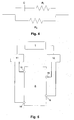
- the impedance response of the subject can be modelled using a suitable model, such the Cole model, which is based on an equivalent circuit that effectively models the electrical behaviour of biological tissue, an example of which is shown in Figure 4 .
- the equivalent circuit includes two branches representing current flow through extracellular fluid and intracellular fluid.
- the extracellular component of biological impedance is represented by a resistance R e
- the intracellular component is represented by a resistance R i and a capacitance C.
- equation (A) can be modified to include an exponent ⁇ to account for the distribution of time constants observed in biological tissues (or systems), as follows:
- Z R ⁇ + R 0 - R ⁇ 1 + j ⁇ ⁇ 1 - ⁇
- R 1 , R e , C and ⁇ are parameters in the model
- Z is the predicted impedance
- j - 1
- f is the frequency of the current passed through the body.
- R 1 and R e are the resistances due to the intracellular and extracellular fluids in the body, respectively.
- a residual variance model is selected to allow variations from the predicted response to be taken into account.
- the residual variance model may be selected in any one of ways as will be described in more detail below.
- parameter estimates are determined that represent the measured responses of the subjects.
- the initial parameters are parameters which when inserted into the models provide an estimate of the response of the sample population.
- a number of Cole models are constructed across the parameter space, using the range of parameter values. This effectively models the range of different impedance responses of the subjects within the population.
- a Fisher information matrix is determined for the residual and Cole models. This can be achieved in any one of a number of ways, but typically involves using suitable applications software, such as the software package POPT by S. B. Duffull, implemented by the processing system 200.
- the product determinant of the Fisher information matrices is optimised: Again, this may be achieved in any one of a number of manners, such as by using a simulated annealing approach to find maxima for the expression. This provides an optimised design which represents the theoretical preferred frequencies at which impedance measurements may be made.
- the optimal design can be used to determine preferred practical frequencies at which impedance measurements may be performed, together with an indication of the relative efficiency of the measurement procedure.
- the above-described process operates by utilising impedance measurements for a sample population to determine optimal design, which can in turn be used to determine preferred frequencies for performing impedance measurements.
- the process is used to determine that in general at least four frequencies should be used for performing impedance measurements. This can also be used to determine preferred frequency ranges for the four frequencies.
- the preferred frequency ranges are as follows:
- the range of frequencies can be further limited to specific values as follows:
- Determination of the frequencies allows an impedance measuring device to be provided, which is adapted to utilise the preferred frequencies, as shown for example in Figure 5 .
- the impedance measuring device typically includes a processing system 1 coupled to a current source 11 and a voltage sensor 12.
- the current source 11 is coupled via electrodes 13, 14 to a subject S with the voltage sensor being coupled to the subject S via electrodes 15, 16.
- the processing system 1 causes the current source 11 to apply alternating current signals to the subject S via the electrodes 13, 14, at each of the preferred frequencies determined using the above described process.
- the response of subject S is then measured via the electrodes 15, 16 using the voltage sensor 12.
- the processing system 1 can then use details of the applied current and the measured voltage signals to determine an impedance value at each of the preferred frequencies.
- parameters of the Cole model By utilising the four measured frequencies, this allows parameters of the Cole model to be determined, such as the subject's impedance at a characteristic frequency Z c , as well as values for the intracellular and extracellular impedance. This in turn allows information such as indicators of the subject's of intracellular or extracellular fluid, or the ratio there between, to be determined.
- the Cole equation described in Cole, K S (1940) Permeability and impermeability of cell membranes for ions Cold Spring Harbor Symposia on Quantitative Biology 8 110-122, is used to model bioimpedance.
- the model includes nonlinear parameters, which are known to vary between individuals. Accordingly the process uses the theory of experimental design to find the frequencies at which measurements of bioimpedance are optimally made. This can also be used to determine how many frequencies are needed in each patient in order to obtain good estimates of the parameters.
- a design ⁇ is D-optimal if it maximizes the determinant of the expected fisher information matrix. That is, arg max ⁇
- Such D-optimal designs therefore, in general provide good estimates of parameters since they minimise the ellipsoidal confidence regions around an estimate.
- a D-efficiency of 0.5 for ⁇ compared with ⁇ * means that twice as many samples need to be taken using ⁇ in order to obtain as accurate parameter estimates as given by ⁇ *
- ⁇ is normally distributed with zero mean and a diagonal variance matrix characterized by parameters s and t so that s relates to the additive error component while t relates to the multiplicative error component.
- ⁇ i is defined by ⁇ + b i
- ⁇ is the vector of fixed effects
- b is the vector of random effects for individual i .
- b i is normally distributed with mean zero and variance ⁇ .
- ⁇ i is defined by g ( ⁇ ,b i ,x i ) , where g is a known function.
- the Fisher information matrix for given values of x is given by: E y
- l ( ⁇ ; y ) is the log-likelihood of observations y for the population parameters ⁇ . Due to the nonlinearity of f with respect to ⁇ , there is no analytical expression for l ( ⁇ ; y ).
- the likelihood can be expressed as: L ⁇ ; Y
- x i , ⁇ i ⁇ L ⁇ ; y i ; b i
- x i , ⁇ i d b i ⁇ L ⁇ ; y i
- this integral is generally intractable.
- One solution for this integral is to approximate the nonlinear function with a first order Taylor expansion around the expected values of the random effects. The model is therefore: y ⁇ f g ⁇ v ⁇ x , ⁇ + ⁇ f ⁇ v ⁇ x , ⁇ ⁇ v ⁇ v - v ⁇ + ⁇ ⁇ s + t f g ⁇ v ⁇ x ⁇ ⁇
- the Fisher information matrices are determined using the software package POPT written by S. B. Duffull.
- the search routine uses an adapted version of a simulated annealing algorithm for continuous variables. Together these techniques provide a means of finding D-optimal designs for nonlinear mixed and fixed effects models across a continuous search space.
- Modelling was performed using the software package MONOLIX, which is a MATLAB based package that uses stochastic approximation to the expectation maximization (SAEM) algorithm, in parametric maximum likelihood estimation for nonlinear mixed effects models.
- SAEM expectation maximization
- the Expectation-Maximization (EM) algorithm is an iterative procedure used for likelihood function maximization given incomplete data sets formed from observable and non observable data.
- the E-step in this algorithm cannot be performed in closed formed due to the nonlinearity in f of the random effects, as described above.
- the SAEM algorithm replaces this step with a stochastic procedure.
- the SAEM replaces this step by drawing b i k from the conditional distribution p (.
- y ; ⁇ k ) and updates Q k ( ⁇ ) as follows: Q k ⁇ Q k - 1 ⁇ + ⁇ k ⁇ log p y b i k ⁇ - Q k - 1 ⁇ where ⁇ k is a decreasing sequence of positive numbers.
- initial parameter estimates are also needed.
- initial estimates of fixed effects were taken from previous studies, and estimates of variance were found by what is called a 'Standard Two Stage Approach'. This involves estimating fixed effects for all data specific to each individual. Then, the variance of these estimates is calculated and used as an estimate for ⁇ .
- the first stage of the modeling process was to find a suitable residual variance model such that the residuals are normally distributed around zero so that tests, such as the likelihood ratio test, are valid. Given the initial estimates, the first run uses a diagonal variance-covariance matrix with all four parameters having a normally distributed random component and the model having additive residuals. The residual plot is shown in Figure 6 .
- This additive variance model can then be compared with the multiplicative and additive plus multiplicative error models.
- the residual plot was best when the additive error model was used.
- the initial model can then be compared with different models having various fixed effects parameters. For example, the initial model can be compared with a model setting the parameter c to have no random component to it, that is having a fixed effect only.
- the likelihood ratio test for nested models can then be used to compare these models with the initial run. In this instance it was found that the initial run significantly increased the log-likelihood to justify having all parameters in the model.
- the final step of the modeling process is to allow some or all of the random effects to have a log-normal distribution. This shows that found parameter estimates were not biologically plausible and can therefore be disregarded.
- the initial model chosen to start the modeling process was the one chosen based on the above reasoning. It was also the model that provided the maximum value of the log-likelihood of ( y; ⁇ ).
- CV% coefficient of variation
- C(E, V) is set to a block matrix of zeros. Then, under this assumption, the fixed and random effects of the model are independent.
- the D-efficiency of the fixed effect design under the mixed effects model is 0.9692.
- Such a high efficiency of the fixed effects D-optimal design suggests that, in this case, accounting for between subject variance only marginally improves the ability to estimate the parameters of the Cole equation.
- An assessment of the preferred model can be made by adding a variance function into the model that mimics the variance of bioimpedance in real life studies.
- the D-optimal design will provide the best estimates of the parameters. Inherent in this design will be the ideal range to restrict our frequencies, based on the variance function used.
- y i f ⁇ i ⁇ i + ⁇ i ⁇ s 1 + s 2 ⁇ h ⁇ 1
- h( ⁇ i ) a function of frequency
- Bioimpedance is made up of two parts, resistance and reactance, relating to the real and imaginary parts of the Cole equation, respectively.
- An example plot of resistance vs reactance is shown in Figure 7 . This plot is of real data and as such shows the real life deviations from the theoretical semi-circle that would be produced from the pure circuit seen in Figure 4 .
- the peak of the locus of the semi-circle identifies the characteristic frequency f c .
- This frequency yields the smallest variance due to the variance function and consequently, it is assumed that at this frequency the constant additive variance dominates.
- the variance function needs to be such that there is relatively small variance between the chosen interval, for example [4, 750], with rapidly increasing variance for frequencies outside these bounds.
- a double exponential model centred around f c , can be used to adequately model the variance of such a study.
- frequencies between f c and 1000 are rescaled to be between 0 and 1.
- frequencies between 0 and f c are rescaled so that they are between 1 and 0.
- the new vector of rescaled frequencies is then exponentiated twice, and scaled such that the vector has a minimum and a maximum at 0 and 1, respectively.
- slightly extra variability is added to frequencies greater than f c by multiplying the rescaled numbers which relate to these frequencies by 2. This whole vector is then multiplied by ⁇ extra 2 .
- Example residual plots of this variance function h ( ⁇ ) for various ⁇ extra 2 values are shown in Figure 8 .
- the log of frequency is shown in all four plots.
- Table 3 shows D-optimal designs found for various values of ⁇ extra 2 .
- the D-efficiencies shown refer to the efficiency of each design compared with the D-optimal design described above.
- the model considered is from equation 16.
- a broad set of preferred frequency ranges can be defined as follows:
- a product design is generally more robust to changes in initial parameter estimates than local D-optimal designs for each parameter set. Thus, a product design is preferred if uncertainty exists in the initial parameter estimates.
- the product design is formed by optimizing over the product of the determinants of the respective variance-covariance matrices of the eight models as a single function.
- the idea behind forming product designs in this way is that optimizing across all eight models will provide a design which is efficient across a wide range of parameter estimates.
- the efficiency of the product design can be calculated by comparing its D-value under each model compared to the D-optimal value under the respective model.
- Table 5 shows the efficiency of the product design compared to each D-optimal design for each parameter set. Relatively high efficiencies across all models suggest that the product design is a good means for allowing for uncertainty in initial parameter estimates. Further, given the range of parameter values considered, it is believed that these designs will efficiently estimate model parameters for a variety of individuals. Hence, this approach and the frequencies found should benefit bioimpedance analysis.
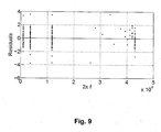
- Figure 9 shows the residual plot for this fit, indicating that the nonlinear regression assumptions discussed above hold.
- Table 7 shows that the coefficients of variation estimated from the full data set are similar to those estimated from the extracted data set. This suggests that only four measurements of impedance per individual are needed to efficiently estimate the parameters of the Cole equation.
- Table 7 Full Data Set Extracted Data Set Expected R 0 2.04 1.76 4.15 R inf 1.58 2.51 6.33 C 2.08 11.11 14.24 ⁇ 1.07 1.57 4.74 18.39 20.09 19.14 19.04 22.04 42.18 19.27 24.48 177.34 16.39 28.69 36.82 s 2 0.93 12.35 9.80
- Table 7 also shows the expected coefficients of variation calculated by using the expected Fisher information matrix to form the expected standard errors of estimates.
- D-optimal designs can also be applied to real data where it was shown to perform well against the full data set. It is hoped that the D-optimal design approach used here and the designs found will aid BIA researchers in the design of optimised multiple frequency BIA instrumentation. This will mitigate the acknowledged inadequacy of some currently used instrumentation and provide for better clinical utility, for example, the accurate prediction of lean body mass for drug dosing in the obese.
Description
- The present invention relates to a method and apparatus for determining frequencies for use in performing impedance measurements on a subject, as well as to a method and apparatus for performing impedance measurements.
- The reference in this specification to any prior publication (or information derived from it), or to any matter which is known, is not, and should not be taken as an acknowledgment or admission or any form of suggestion that the prior publication (or information derived from it) or known matter forms part of the common general knowledge in the field of endeavour to which this specification relates.
- Bioelectrical Impedance Analysis (BIA) measures the impedance to flow of an alternating electrical current passed through biological tissue. Such impedance measurements are typically performed at a number of different frequencies, allowing a subject's impedance response to be modelled, using a mathematic relationship, such as the Cole model. This in turn enables the estimation of various parameters, which can in turn be used to derive information regarding a subject's health.
- However, the frequencies used are typically selected randomly, or based on the ability of the measuring device used to perform the measurements. Consequently the effectiveness and accuracy of the measurements varies greatly.
- "Bioimpedance Spectrometry in the Determination of Body Water Compartments: Accuracy and Clinical Significance" by B. J. THOMAS*1, L. C. WARD2 and B. H. CORNISH Appl. Radiat. Isot. Vol. 49, No. 5/6, pp. 447-455, 1998 describes that bioelectrical impedance analysis (BIA) offers the potential for a simple, portable and relatively inexpensive technique for the in vivo measurement of total body water (TBW) and body composition. The document also discusses multi-frequency BIA (MFBIA) which can be used in the independent assessment not only of TBW but also of the extracellular fluid volume (ECW). The document considers the principles, methodology and applications of BIA, the basic theory of BIA and the relative merits of single and multiple frequency BIA.
-
WO 01/67098 - In a first broad form the present invention provides a method of determining frequencies for use in performing impedance measurements according to
claim 1, the method including: - a) determining estimates for parameter values representing an impedance response for at least one subject;
- b) using the estimated parameter values to determine a design; and,
- c) using the design to determine frequencies for use in impedance measurements.
- Typically the method includes, determining the estimates for the parameter values at least in part using a model of the subject's impedance response.
- Typically the method includes:
- a) determining a residual variance model having a predetermined distribution; and,
- b) determining the estimates for the parameter values at least in part using the selecting variance model.
- Typically the method of determining the residual variance model includes using an expectation maximization algorithm.
- Typically the method includes determining a range of parameter values representing the impedance response of a number of subjects.
- Typically the method includes:
- a) determining a Fisher information matrix for a model of the impedance response of the at least one subject; and,
- b) determining a design using the Fisher information matrix.
- Typically the model includes at least one of:
- a) A Cole model; and,
- b) A residual variance model.
- Typically the model includes determining the design by optimising the determinant of the Fisher information matrix.
- Typically the design is a D-optimal design.
- Typically the method includes determining a design space to take into account practical limitations.
- Typically the method includes, modifying the design by at least one of:
- a) restricting the frequencies; and,
- b) providing an error structure as a function of frequency.
- Typically the method is performed at least in part using a processing system.
- Typically the method includes, in the processing system:
- a) determining impedance data representing the impedance response of the at least one subject; and,
- b) using the impedance data to determine the estimates for the parameter values.
- Typically the method includes, in the processing system:
- a) determining an impedance model; and,
- b) using the impedance model and the estimated parameter values to determine the design.
- Typically the method includes, in the processing system:
- a) calculating a Fisher information matrix for the model; and,
- b) using the Fisher information matrix to determine the design.
- Typically the method includes, in the processing system, optimising a determinant of the Fisher information matrix for the model.
- Typically the method includes, in the processing system:
- a) receiving limits on applicable frequencies; and,
- b) using the limits and the design to determine the frequencies.
- Typically the method includes, in the processing system, determining frequencies for use in impedance measurements within the range :
- a) 0-50 kHz;
- b) 2-200 kHz;
- c) 50-500 kHz; and,
- d) 200-1000 kHz.
- Typically the frequencies are within the ranges:
- a) 0-24 kHz;
- b) 5-74 kHz;
- c) 77-200 kHz;
- d) 530-1000 kHz.
- Typically the frequencies are:
- a) 14 kHz
- b) 57 kHz
- c) 188 kHz
- d) 679 kHz
- Typically the frequencies are:
- a) 14.1844 kHz
- b) 56.9201 kHz
- c) 187.5397 kHz
- d) 679.1141 kHz
- In a second broad form the present invention provides apparatus according to claim 11 for determining frequencies for use in performing impedance measurements, the apparatus including, a processing system for:
- a) determining estimates for parameter values representing an impedance response for at least one subject;
- b) using the estimated parameter values to determine a design; and,
- c) using the design to determine frequencies for use in impedance measurements.
- Typically the apparatus is for performing the first broad form of the invention.
- In a third broad form the present invention provides a method of measuring the impedance of a subject the method including, the method including, in a measuring device.
- a) causing one or more electrical signals to be applied to the subject using a first set of electrodes, the one or more electrical signals having four frequencies;
- b) measuring electrical signals across a second set of electrodes applied to the subject in response to the applied one or more signals;
- c) determining from the applied signals and the measured signals at least one measured impedance value at each of the four frequencies, wherein the four frequencies are in the ranges:
- i) 0-50 kHz;
- ii) 2-200 kHz;
- iii) 50-500 kHz; and,
- iv) 200-1000 kHz.
- Typically a restricted range of frequencies can be defined by the ranges:
- a) 0-24 kHz;
- b) 5-74 kHz;
- c) 77-200 kHz;
- d) 530-1000 kHz.
- Typically the frequencies are approximately:
- a) 14 kHz
- b) 57 kHz
- c) 188 kHz
- d) 679 kHz
- Typically the frequencies are:
- a) 14.1844 kHz
- b) 56.9201 kHz
- c) 187.5397 kHz
- d) 679.1141 kHz
- Typically the method includes determining one or more impedance parameter values based on the plurality of measured impedance values.
- In a fourth broad form the present invention provides apparatus for measuring the impedance of a subject the apparatus including a measuring device for:
- a) causing one or more electrical signals to be applied to the subject using a first set of electrodes, the one or more electrical signals having four frequencies;
- b) measuring electrical signals across a second set of electrodes applied to the subject in response to the applied one or more signals;
- c) determining from the applied signals and the measured signals at least one measured impedance value at each of the four frequencies, wherein the four frequencies are in the ranges:
- i) 0-50 kHz;
- ii) 2-200 kHz;
- iii) 50-500 kHz; and,
- iv) 200-1000 kHz.
- Typically the measuring device includes:
- a) a current source for applying current signals to the subject;
- b) a voltage sensor for measuring voltages signals across the subject; and,
- c) a processing system could to the current source and the voltage sensor for:
- i) causing the current signals to be applied to the subject; and,
- ii) determining the impedance using the applied current signals and measured voltage signals.
- Typically the apparatus is for performing the method of the third broad form of the invention.
- Examples of the present invention will now be described with reference to the accompanying drawings, in which: -
-
Figure 1 is a flow chart of an example of a process for determining frequencies for use in performing impedance measurements; -
Figure 2 is a schematic diagram of an example of a processing system for use in determining frequencies; -
Figure 3 is a flow chart of a specific example of a process for determining frequencies for use in performing impedance measurements; -
Figure 4 is a schematic diagram of an example of an "idealised" equivalent circuit for the Cole model; -
Figure 5 is a schematic diagram of an example of apparatus for measuring impedance; -
Figure 6 is an example of a residual plot for determining an initial model fit; -
Figure 7 is an example of a resistance versus reactance plot for example impedance measurements; -
Figure 8 is an example of plots of a variance function for various values of σ2; and, -
Figure 9 is an example of a plot of residuals from a model fit using an example extracted data set. - An example of a process for determining frequencies at which impedance measurements may be made will now be described with reference to
Figure 1 . - At
step 100 parameter values are determined representing the impedance response of one or more subjects. The parameter values may be determined in any one of a number of manners, such by modelling impedance data collected from a number of subjects from a prior study, as will be described in more detail below. - At
step 110 the parameter values are used to determine an optimal design for studying the impedance response of the one or more subjects. This can be achieved, by optimising designs representing frequencies that may be used in performing impedance measurements according to optimality criteria. - At
step 120 the optimal designs may optionally be modified to take into account practical effects, such as the variants of subjects within a population to impedance measurement. - At
step 130 the optimal designs are used to determine frequencies that may be used for performing impedance measurements. - The process may be performed manually, but typically requires advanced computation and therefore typically requires the use of a processing system.
- An example processing system is shown in
Figure 2 . In this example, theprocessing system 200 is formed from aprocessor 210, amemory 211, an input/output device 212 and an optionalexternal interface 213 interconnected via abus 214. Theexternal interface 213 may be used to couple theprocessing system 200 to adatabase 220. - In use the
processing system 200 executes applications software stored in thememory 211, to allow parts of the process to be performed, as will be described in more detail below. It will be appreciated from this that theprocessing system 200 may be any suitable form ofprocessing system 200, such as a personal computer, desktop, laptop, super computer, Sparc station, or the like. - An example of the process will now be described in more detail with respect to
Figure 3 . - In this example, at
step 300 impedance data is collected from a sample population of subjects. The data is collected using a suitable measuring device that applies alternating electrical signals to a subject, and measures the electrical response of the subject. This is typically achieved by applying alternating currents to the subject at a number of different frequencies, and then measures voltage signals across the subject, to allow the impedance to be determined at each frequency. An example measuring device will be described in more detail below. - The impedance response of the subject can be modelled using a suitable model, such the Cole model, which is based on an equivalent circuit that effectively models the electrical behaviour of biological tissue, an example of which is shown in
Figure 4 . - In this example, the equivalent circuit includes two branches representing current flow through extracellular fluid and intracellular fluid. The extracellular component of biological impedance is represented by a resistance Re, whilst the intracellular component is represented by a resistance Ri and a capacitance C.
- Accordingly, the impedance of the equivalent circuit of
Figure 4 at an angular frequency ω, where ω=2π*frequency, is given by:
where: - R∞= impedance at infinite applied frequency = RiRe/(Ri+Re),
- R0= impedance at zero applied frequency = Re and,
- τ is the time constant of the capacitive circuit.
- However, as an alternative to the equivalent circuit described above, an alternative equivalent circuit incorporating a Fricke constant phase element (CPE) can be used, as will be understood by persons skilled in the art.
- In any event, the equation (A) can be modified to include an exponent α to account for the distribution of time constants observed in biological tissues (or systems), as follows:

- In this equation, R 1 , Re, C and α are parameters in the model, Z is the predicted impedance,

- However, this is a theoretical model and in practice a subject's response will vary. Accordingly, at step 310 a residual variance model is selected to allow variations from the predicted response to be taken into account. The residual variance model may be selected in any one of ways as will be described in more detail below.
- At
step 320, parameter estimates are determined that represent the measured responses of the subjects. The initial parameters are parameters which when inserted into the models provide an estimate of the response of the sample population. - It will be appreciated that as different subjects within the sample population will have a range of different responses to impedance measurements. Accordingly, it is typical to model the range of responses across the sample population to allow the mean and variability of the parameters between subjects to be determined. This is effectively used to define a range of parameter values representing a parameter space.
- At
step 330, a number of Cole models are constructed across the parameter space, using the range of parameter values. This effectively models the range of different impedance responses of the subjects within the population. - At step 340 a Fisher information matrix is determined for the residual and Cole models. This can be achieved in any one of a number of ways, but typically involves using suitable applications software, such as the software package POPT by S. B. Duffull, implemented by the
processing system 200. - At
step 350, the product determinant of the Fisher information matrices is optimised: Again, this may be achieved in any one of a number of manners, such as by using a simulated annealing approach to find maxima for the expression. This provides an optimised design which represents the theoretical preferred frequencies at which impedance measurements may be made. - However, certain frequency measurements may not be practically achievable, or desirable. Thus, for example, theory may predict that the application of an
electrical signal 0 kHz frequency will result in an improved subject response and hence improved impedance measurements. However, as the application of such a frequency is not practical, such a frequency is usually excluded. Similarly, high frequency measurements whilst theoretically advantageous, can be difficult to measure from a practical point of view, thereby further limiting the range of available frequencies. Accordingly, atstep 360, a design space is selected that can be used to exclude such impractical frequencies. - At
step 370 the optimal design can be used to determine preferred practical frequencies at which impedance measurements may be performed, together with an indication of the relative efficiency of the measurement procedure. - Accordingly, the above-described process operates by utilising impedance measurements for a sample population to determine optimal design, which can in turn be used to determine preferred frequencies for performing impedance measurements.
- In one example, described in more detail in the specific example below, the process is used to determine that in general at least four frequencies should be used for performing impedance measurements. This can also be used to determine preferred frequency ranges for the four frequencies.
- In one example, the preferred frequency ranges are as follows:
- 0-50 kHz;
- 2-200 kHz;
- 50-500 kHz; and,
- 200-1000 kHz.
- Limiting the design space based on practical constraints can lead to more specific frequency ranges as follows:
- 0-24 kHz;
- 5-74 kHz;
- 77-200 kHz;
- 530-1000 kHz.
- Even more preferably, the range of frequencies can be further limited to specific values as follows:
- 14 kHz
- 57 kHz
- 188 kHz
- 679 kHz
- These are based on theoretical preferred frequencies calculated to be as follows:
- 14.1844 kHz
- 56.9201 kHz
- 187.5397 kHz
- 679.1141 kHz
- Determination of the frequencies allows an impedance measuring device to be provided, which is adapted to utilise the preferred frequencies, as shown for example in
Figure 5 . - In this example the impedance measuring device typically includes a
processing system 1 coupled to acurrent source 11 and avoltage sensor 12. Thecurrent source 11 is coupled viaelectrodes electrodes - In use the
processing system 1 causes thecurrent source 11 to apply alternating current signals to the subject S via theelectrodes electrodes voltage sensor 12. Theprocessing system 1 can then use details of the applied current and the measured voltage signals to determine an impedance value at each of the preferred frequencies. - By utilising the four measured frequencies, this allows parameters of the Cole model to be determined, such as the subject's impedance at a characteristic frequency Zc, as well as values for the intracellular and extracellular impedance. This in turn allows information such as indicators of the subject's of intracellular or extracellular fluid, or the ratio there between, to be determined.
- A specific example of the above process will now be described in more detail.
- In this example, the Cole equation described in Cole, K S (1940) Permeability and impermeability of cell membranes for ions Cold Spring Harbor Symposia on
Quantitative Biology 8 110-122, is used to model bioimpedance. The model includes nonlinear parameters, which are known to vary between individuals. Accordingly the process uses the theory of experimental design to find the frequencies at which measurements of bioimpedance are optimally made. This can also be used to determine how many frequencies are needed in each patient in order to obtain good estimates of the parameters. - Much of experimental design focuses on parameter estimation. A design is optimized, that is, the best choice of covariate settings and experimental effort is chosen, through assessment of an optimality criterion. Criteria considered in this paper are D-optimality and product design optimality, which are typically used to gain good parameter estimates for one or more models. Such criteria are based on the expected Fisher information matrix described in more detail below:
- A Design ξ is defined by:

where wi is the experimental effort given to the i -th vector of covariates xi. - Use of the experimental effort factor is optional and included in this design for the purpose of example only and the following discussion will focus in examples in which the experimental effort is not taken into account, in which case the preferred Design ξ is defined by

If xi ∈ χ, then the design space can be written as
- For a model with response vector y = (y 1 , ... , yn), dependent upon parameters θ and a design ξ, the expected Fisher information matrix can be defined as:

where l(θ; y) is the log-likelihood. - The Cramer-Rao lower bound described in H. Cramer "Mathematical methods of statistics." Princeton, NJ: Princeton University Press, pages 474-477, 1946, states that the variance-covariance matrix of any unbiased estimator of θ is bounded below by M -1 (θ,ξ). Thus, for given a design ξ, the expected Fisher information indicates how well to estimate the parameters in the model.
- A design ξ is D-optimal if it maximizes the determinant of the expected fisher information matrix. That is, arg maxξ|M(θ,ξ)|. This design will minimize |M -1(θ,ξ)| which, minimizes the variance-covariance of θ̂. Such D-optimal designs, therefore, in general provide good estimates of parameters since they minimise the ellipsoidal confidence regions around an estimate.
- When comparing a designs ability to estimate model parameters, its D-efficiency is considered. The D-efficiency of the design ξ compared to the D-optimal design ξ * for a particular model is:

where pi is the number of parameters in the model. - A D-efficiency of 0.5 for ξ compared with ξ * means that twice as many samples need to be taken using ξ in order to obtain as accurate parameter estimates as given by ξ *
- Product design is found when trying to obtain efficient parameter estimates for more than one model. Here the product of the determinants, scaled by the number of parameters, of each model is maximized giving a design ξ *D 1 ,D 2 which should yield good parameter estimates under each model. That is,

where M 1(θ 1,ξ) is the expected Fisher information matrix formodel 1 with parameters θ 1 and p 1 is the number of model parameters. Similarly formodel 2. - A nonlinear model is specified by two main parts; a function expressing the predicted response and residual response variance structure. This, for the jth observation, can be written as follows:

where: - yj is the jth predicted response,
- xj are the covariates,
- θ refers to the model parameters and
- εj is error or uncertainty in the response for a given individual.
- When modelling nonlinear data it is assumed that:
- (i) E└εj ┘= 0; for j = 1, ... ,m
- (ii) Cor└εj,εl ┘= 0; for j = 1, ... ,m and for l = 1, ...,m
- (iii) Var[εj ] = σ2 , and are identically distributed for all xi for j = 1, ... ,m;
- (iv) εj ∼ N(µ,σ 2) for j = 1, ... ,m.
- Often in practical applications, some of these assumptions do not hold. Accordingly, some generalizations or relaxations of this framework can be used so that the theory of nonlinear regression can be applied in these areas.
- One relaxation is a generalization of the assumption of constant variance. Such a relaxation will allow flexibility in specifying intra-individual variance. This involves specifying a variance function h which can depend upon the predicted response E[yj], covariates xj and/or additional parameters δ. The model is then specified by:


- Such a specification generalizes assumption (iii) and allows for heteroscedasticity in the model.
- The above defines a fixed effects model. However, to take into account variations between individuals, mixed effects models are typically used.
- For a single individual, a fixed effects model (of the form yi = f(xi,θ)+εi ) is considered. The expected fisher information matrix is defined as follows:

where:
and W is adiagonalized nx 1 vector of weights and
- Mixed effects models allow for the analysis of individual data by incorporating fixed and random effects into a model. This gives two sources of variation; residuals within individuals and variation between individuals. Accordingly, the models have two types of coefficients; population-average and individual specific. One of the main applications of this theory is to repeated measures data.
- It is known that where yi is a ni -vector of observations for the i-th individual, where i = 1, . .. , N, and let the model be described by F(θi,ξi ). Then:

where ξi = (x i1,...,x ini )' is a ni -vector of explanatory variables for the individual i, θi is the p-vector of individual parameters and εi is the ni -vector of random errors. - Here ε is normally distributed with zero mean and a diagonal variance matrix characterized by parameters s and t so that s relates to the additive error component while t relates to the multiplicative error component.
- Where θi is defined by β+bi, β is the vector of fixed effects and b is the vector of random effects for individual i. Here bi is normally distributed with mean zero and variance Ω.
- The covariates for individual i is denoted by the vector xi , and θi is defined by g(β,bi,xi ), where g is a known function. Ψ is an estimate of a vector of all population parameters, let γ be the vector of all variance terms. Then, Ψ'=[β',γ']
- The Fisher information matrix for a population design

- The Fisher information matrix for given values of x is given by:

where l(θ;y) is the log-likelihood of observations y for the population parameters θ. Due to the nonlinearity of f with respect to θ, there is no analytical expression for l(θ;y). That is, in general; for say N individuals where Y is a matrix of responses for the whole population and yi is the vector of responses for the ith individual, the likelihood can be expressed as:
where
- Given the nonlinearity of bi in f, this integral is generally intractable. One solution for this integral is to approximate the nonlinear function with a first order Taylor expansion around the expected values of the random effects. The model is therefore:

- Then the log-likelihood I is approximated by:

where E and V are the marginal expectation and variance of y given by:

- Then the Fisher information matrix can be expressed as:

where


- Thus, the approximate expected information matrix for a nonlinear mixed effects model is formed. This can now be used in a variety of optimality criteria to form designs with desired properties.
- The application of these techniques to Bioelectical impedance analysis (BIA), as modeled using the Cole equation, will now be explained. In particular D-optimal designs are derived based on different assumptions about the interaction between frequency and impedance and also the practical limitations of such a study.
- This is achieved by obtaining initial parameter estimates by modeling data on individuals, using these initial estimates to form D-optimal designs and then extending these D-optimal designs so that they perform well in practice.
- In this example the Fisher information matrices are determined using the software package POPT written by S. B. Duffull. The search routine uses an adapted version of a simulated annealing algorithm for continuous variables. Together these techniques provide a means of finding D-optimal designs for nonlinear mixed and fixed effects models across a continuous search space.
- For the Cole equation, initial parameter estimates were found by modeling paired frequency and bioimpedance data on 61 subjects. Whole-body, wrist to ankle, multifrequency bioimpedance data were recorded over the
frequency range 5 to 1024 kHz using an Impedimed-SEAC SFB3 tetra-polar impedance instrument. - Modelling was performed using the software package MONOLIX, which is a MATLAB based package that uses stochastic approximation to the expectation maximization (SAEM) algorithm, in parametric maximum likelihood estimation for nonlinear mixed effects models.
- The Expectation-Maximization (EM) algorithm is an iterative procedure used for likelihood function maximization given incomplete data sets formed from observable and non observable data. The E-step in this algorithm cannot be performed in closed formed due to the nonlinearity in f of the random effects, as described above.
- The SAEM algorithm replaces this step with a stochastic procedure. Thus, the usual EM algorithm computes, at the kth iteration, the conditional expectation of the log-likelihood giving Qk (Ψ)=E[logp(y,bi ;Ψ)|y,Ψ k-1)], where p(y,bi ;Ψ) is the likelihood of (y,bi ).
- The SAEM replaces this step by drawing


where δk is a decreasing sequence of positive numbers. - To fit a nonlinear model to data, initial parameter estimates are also needed. For this model, initial estimates of fixed effects were taken from previous studies, and estimates of variance were found by what is called a 'Standard Two Stage Approach'. This involves estimating fixed effects for all data specific to each individual. Then, the variance of these estimates is calculated and used as an estimate for Ω.
- The first stage of the modeling process was to find a suitable residual variance model such that the residuals are normally distributed around zero so that tests, such as the likelihood ratio test, are valid. Given the initial estimates, the first run uses a diagonal variance-covariance matrix with all four parameters having a normally distributed random component and the model having additive residuals. The residual plot is shown in
Figure 6 . - This shows that the assumption about additive variance holds reasonably well and the residuals are centered around zero. Whilst the plot is not completely random at low frequencies, due for example to technical errors of measurements and inaccuracies associated with using the Cole equation to model bioelectrical impedance, this is considered acceptable.
- This additive variance model can then be compared with the multiplicative and additive plus multiplicative error models. The residual plot was best when the additive error model was used.
- The initial model can then be compared with different models having various fixed effects parameters. For example, the initial model can be compared with a model setting the parameter c to have no random component to it, that is having a fixed effect only. The likelihood ratio test for nested models can then be used to compare these models with the initial run. In this instance it was found that the initial run significantly increased the log-likelihood to justify having all parameters in the model.
- The final step of the modeling process is to allow some or all of the random effects to have a log-normal distribution. This shows that found parameter estimates were not biologically plausible and can therefore be disregarded.
- In the end, the initial model chosen to start the modeling process was the one chosen based on the above reasoning. It was also the model that provided the maximum value of the log-likelihood of (y;θ).
- Using the model described above, the final estimates can be found in table 1, where the random effects are normally distributed around zero with variance SZ; a diagonal matrix with
diagonal elements 
Table 1. Parameter Estimate (CV%) R0 861.00 (2.04) Rinf 320 (1.58) C 2.4e-006 (2.08) α 0.649 (1.07) 
1.92e+004 (18.39) 
1.66e+003 (19.04) 
1.64e-013 (19.27) 
0.00302 (16.39) s 2 5.46 (0.93) - It will be appreciated that these values are derived from actual physical measurements and will therefore depend on collected data. The above values are therefore for the purpose of illustration only and are not intended to be limiting.
- A coefficient of variation (CV%) is calculated by dividing the standard error of an estimate by its estimate and multiplying this by 100 to form a percentage. Typically, acceptable CV%'s for fixed parameters and random parameters are 20% and 50%, respectively. From the table 1, we can see that the CV%'s for our estimates are more than reasonable.
- Examining a design for one individual using the fixed effects model will now be described using the initial estimates found in the previous section, θ = [R 0 ,Rinf,C,α]'= [861, 320, 2.4e-006, 0.649]'. The design which maximises the determinant of the information matrix is:

- However, as described above, this is for the values shown in Table 1 and if different values are used, a different matrix will be determined.
- D-optimality generally selects extreme values of covariates, but this also occurs to an extent due to the nature of the Cole equation. If
ω approaches zero, the Cole equation will approach Z =R 0. Alternatively, ifω approaches infinity Z = R ∞. Thus, extreme frequencies provide simpler expressions for R 0 and R ∞. - The calculation of the D-efficiency will be described below, providing an indication of the limitation of not accounting for between subject variability seen in the next section.
- For the Cole equation, parameter estimates are known to vary between subjects, and accordingly a mixed effects model must be used.
- For the purpose of this analysis it will be assumed that it is possible to administer electrical currents through the, body at frequencies [0, 1000] kHz, and obtain an accurate reading of bioelectrical impedance Thus, this can assume a model:

- Using the initial estimates from the fixed effects model determined above, and shown in table 1, the following D-optimal design was found by maximizing the determinant of equation 11:

- When forming the expected fisher information matrix for this design, C(E, V) is set to a block matrix of zeros. Then, under this assumption, the fixed and random effects of the model are independent.
- The D-efficiency of the fixed effect design under the mixed effects model is 0.9692. Such a high efficiency of the fixed effects D-optimal design suggests that, in this case, accounting for between subject variance only marginally improves the ability to estimate the parameters of the Cole equation.
- With bioelectrical impedance studies, it is known that low and high frequencies produce more highly variable readings of bioimpedance compared with less extreme frequencies.
- Two possible approaches to account for this variability will now be described. The first restricts the design space to exclude frequencies where readings of bioimpedance are inaccurate. The second allows the residual variance to depend on the frequency in some manner that mimics real life patterns.
- The straight forward approach to dealing with such a variance structure is to avoid frequencies which produce highly variable bioimpedance measures. At present, such bioimpehdance studies limit the frequencies to being between a variety of ranges due to this added variability Examples of such ranges are [4, 200], [4, 500] and [4, 750]. These intervals, therefore are used to define restricted designs.
- Allowing parameters to vary between individuals the following D-optimal designs were found for the above example:
Table 2 Range Frequency D-eff under Mixed Effects Design [4, 200] 4.0000 0.4320 15.1909 60.4311 200.0000 [4, 500] 4.0000 0.5977 18.8903 114.7364 500.0000 [4, 750] 4.0000 0.06752 21.5242 143.0364 750.0000 - The D-efficiencies of these restricted designs under the mixed effects models are also shown in table 2. As the range becomes more restricted, the efficiencies decrease. This is highlighted by the D-efficiencies of these designs, which suggest that, under the assumption of constant additive variance, restricting the frequencies to certain intervals creates a significant loss in our ability to estimate parameters precisely. Consequently we will be forced to sample more often in the restricted case to obtain as precise estimates as in the unrestricted case.
- An assessment of the preferred model can be made by adding a variance function into the model that mimics the variance of bioimpedance in real life studies.
- In this case, once the true variance structure has been captured by the function, the D-optimal design will provide the best estimates of the parameters. Inherent in this design will be the ideal range to restrict our frequencies, based on the variance function used.
- To achieve this, a model of the following form is used:

where h(ξi), a function of frequency, specifies the variance function. - Relaxing the assumption about constant variance of the residuals by forming a variance function described above, allows accurate capture and mimicking of the residual structure, without violating any nonlinear regression assumptions.
- Bioimpedance is made up of two parts, resistance and reactance, relating to the real and imaginary parts of the Cole equation, respectively. An example plot of resistance vs reactance is shown in
Figure 7 . This plot is of real data and as such shows the real life deviations from the theoretical semi-circle that would be produced from the pure circuit seen inFigure 4 . - The peak of the locus of the semi-circle identifies the characteristic frequency fc . This frequency yields the smallest variance due to the variance function and consequently, it is assumed that at this frequency the constant additive variance dominates. The variance function needs to be such that there is relatively small variance between the chosen interval, for example [4, 750], with rapidly increasing variance for frequencies outside these bounds.
- Accordingly, a double exponential model, centred around fc , can be used to adequately model the variance of such a study. Thus, for the
range 0 kHz to 1000 kHz, frequencies between fc and 1000 are rescaled to be between 0 and 1. Similarly, frequencies between 0 and fc are rescaled so that they are between 1 and 0. The new vector of rescaled frequencies is then exponentiated twice, and scaled such that the vector has a minimum and a maximum at 0 and 1, respectively. Finally, slightly extra variability is added to frequencies greater than fc by multiplying the rescaled numbers which relate to these frequencies by 2. This whole vector is then multiplied by σ extra 2. - Example residual plots of this variance function h(ξ) for various σextra 2 values are shown in
Figure 8 . In order to illustrate the variation of impedance at small frequencies, the log of frequency is shown in all four plots. - From this it can be seen that the actual structure of the function does not change, but is merely at a different scale. This also shows how variable readings of bioimpedance can be at low and high frequencies, particularly when σextra 2 is large, and how there exists relatively small variance between 4 and 750.
- This leads to another consideration for this variance structure, in particular, how much should bioimpedance vary at low and high frequencies, and therefore how large should σextra 2 be such that it will capture the real life variance structure of bioimpedance.
- Table 3 shows D-optimal designs found for various values of σextra 2 . The D-efficiencies shown refer to the efficiency of each design compared with the D-optimal design described above. For all designs, the model considered is from
equation 16.Table 3 σextra 2 ξD*multi D- eff 0 0.0001 1.0000 5.0371 77.4409 1000.000 0.1 0.0001 0.6837 15.3454 109.5900 699.9127 0.2 14.6420 0.6383 59.5391 186.4495 680.5794 0.5 20.6291 0.5831 68.7527 183.2815 595.1341 1 25.7367 0.5409 74.3527 175.7765 530.8203 - This shows that as the variance increases at the low and high frequencies, the criterion starts to choose frequencies at the less extreme values, thereby avoiding regions which relate to a highly variable reading of bioimpedance. Thus, it is up of the experimenter to decide how variable bioimpedance can be. Once this is decided, the D-optimal design will take this variability into account and find the design which will give the best estimates of parameters:
- For example, at a first instance, a broad set of preferred frequency ranges can be defined as follows:
- 0-50 kHz;
- 2-200 kHz;
- 50-500 kHz and,
- 200-1000 kHz.
- However, using a more limited design space based on the above mentioned practical constraints can lead to more specific frequency ranges as follows:
- 0-24 kHz;
- 5-74 kHz;
- 77-200 kHz;
- 530-1000 kHz.
- In a more extreme limitation, for example, assuming σ2 = 0.2 is a true representation of the variance, then the optimal design can be seen in the above table, indicating that measurements at frequencies lower than 14.64 kHz and higher than 680.60 kHz are too variable and should be avoided.
- Inaccurate prior estimates of parameters for nonlinear models can lead to designs that have a limited ability to estimate parameters that diverse considerably from what was expected. In order to find a design that offers efficient parameter estimates across a wide range of prior estimates, we can look at product design optimality discussed above.
- A product design is generally more robust to changes in initial parameter estimates than local D-optimal designs for each parameter set. Thus, a product design is preferred if uncertainty exists in the initial parameter estimates.
- Given the initial parameters estimates above, 5th and 95th percentiles of the population can be found using the estimates of the between subject variability. For example, given the initial estimate of R 0 = 861 with ω 1 = 138, the 5th and 95th percentiles would be 584 and 1138, respectively.
- Such percentiles can be determined for all four model parameters giving a set of eight different initial estimates which would be used as eight different impedance models in the product design. The eight parameter sets considered can be seen in table 4.
Table 4 Model R0 Rinf C α 1 1138 370 2.40e-06 0.6490 2 584 370 2.40e-06 0.6490 3 861 401 2.40e-06 0.6490 4 861 239 2.40e-06 0.6490 5 861 320 3.21e-06 0.6490 6 861 320 1.59e-06 0.6490 7 861 320 2.40e-06 0.7589 8 861 320 2.40e-06 0.5391 - The product design is formed by optimizing over the product of the determinants of the respective variance-covariance matrices of the eight models as a single function. The idea behind forming product designs in this way is that optimizing across all eight models will provide a design which is efficient across a wide range of parameter estimates. The model considered is of the form of equation 16 (σextra 2=0.2), the values for which are set out in Table 3 as:

- The following product design is given by:

- To analyze how efficient the product design is at estimating parameters across all models, the efficiency of the design under each model is determined, as shown in table 5, in which the efficiency of the product design is compared to each D-optimal design for each parameter set.
Table 5 Model D- eff 1 0.9923 2 0.9932 3 0.9890 4 0.8129 5 0.9573 6 0.7298 7 0.9982 8 0.9997 - The efficiency of the product design can be calculated by comparing its D-value under each model compared to the D-optimal value under the respective model. Table 5 shows the efficiency of the product design compared to each D-optimal design for each parameter set. Relatively high efficiencies across all models suggest that the product design is a good means for allowing for uncertainty in initial parameter estimates. Further, given the range of parameter values considered, it is believed that these designs will efficiently estimate model parameters for a variety of individuals. Hence, this approach and the frequencies found should benefit bioimpedance analysis.
- A practical approach, applies real data to determine how well model parameters can be estimated. Given the design:

and the data on 61 individuals, impedance at these frequencies were extracted from the data set of all individuals and a nonlinear mixed effects model was fitted to this extracted data set. Using the same model and initial parameter estimates as discussed in the modelling section above, MONOLIX provides estimates for the parameter values as shown in table 6 and estimates of coefficients of variation found in table 7.Table 6 Parameter Full Data Set Extracted Data Set R0 861 879 R inf320 303 C 2.4e-006 3.25e-006 α 0.649 0.68 
1.92e+004 1.1e+04 
1.66e+003 1.52e+003 
1.64e-013 5.31e-012 
30.2e-003 1.37e-003 s 2 5.46 5.24 -
Figure 9 shows the residual plot for this fit, indicating that the nonlinear regression assumptions discussed above hold. - The new estimates shown in table 6 are similar to those found using the full data set of observations. Given this and the residual plot, it is concluded that this D-optimal design performs well in practice and as such, with the use of only four frequencies, we have been able to form estimates of parameters of the Cole equation similar to those found by using the full data set.
- It is also clear that the product design performs well in practice and requires of only four frequencies per individual. That is, the optimal choice of these frequencies yields the ability to efficiently estimate model parameters. Further, it highlights the apparent lack of information gained by choosing over 100 unique frequencies per individual to model bioimpedance.
- Table 7 shows that the coefficients of variation estimated from the full data set are similar to those estimated from the extracted data set. This suggests that only four measurements of impedance per individual are needed to efficiently estimate the parameters of the Cole equation.
Table 7 Full Data Set Extracted Data Set Expected R0 2.04 1.76 4.15 Rinf 1.58 2.51 6.33 C 2.08 11.11 14.24 α 1.07 1.57 4.74 
18.39 20.09 19.14 
19.04 22.04 42.18 
19.27 24.48 177.34 
16.39 28.69 36.82 s 2 0.93 12.35 9.80 - Table 7 also shows the expected coefficients of variation calculated by using the expected Fisher information matrix to form the expected standard errors of estimates.
- Accordingly, this shows that experimental design for nonlinear fixed and mixed effects models can be applied BIA, allowing preferred frequency measuring models to be determined. Numerous four frequency designs were found relating to D-optimal designs based on various assumptions about how frequency relates to bioimpedance and how parameters vary between individuals. Product designs were also found. These designs should be robust to changes in initial estimates.
- D-optimal designs can also be applied to real data where it was shown to perform well against the full data set. It is hoped that the D-optimal design approach used here and the designs found will aid BIA researchers in the design of optimised multiple frequency BIA instrumentation. This will mitigate the acknowledged inadequacy of some currently used instrumentation and provide for better clinical utility, for example, the accurate prediction of lean body mass for drug dosing in the obese.
Claims (11)
- A method of determining frequencies for use in performing impedance measurements, the method including:a) obtaining impedance data from a sample population (300);b) determining estimates for parameter values (320) of parameters (Ri, Re, C) in an impedance model that effectively models the electrical behaviour of biological tissue, the parameter values representing an impedance response for a subject, the estimates representing the measured responses of subjects of the sample population, characterised in that the method comprises determining estimates for the parameter values by:i) determining (310) a residual variance model having a predetermined distribution, and,ii) determining (320) estimates for the parameter values using the residual variance model, the impedance data and said impedance modeland wherein the method further includes using the estimated parameter values to determine a design (110) by:i) constructing (330) a number of constructed impedance models using different estimated parameter value and said impedance modelii) determining a Fisher information matrix for each of the constructed impedance models (340); andiii) optimising the product of the determinants of the Fisher information matrices to determine a design representing frequencies for use in impedance measurements; and (e) using the design to determine frequencies for use in impedance measurements (370).
- A method according to claim 1, wherein the method of determining the residual variance model includes using an expectation maximization algorithm.
- A method according to claim 1 or claim 2, wherein the method includes determining a range of parameter values representing the impedance response of a number of subjects.
- A method according to any one of the claims 1 to 3, wherein the method includes determining a design space to take into account practical limitations by excluding frequency measurements which may not be practically achievable, or desirable.
- A method according to claim 4, wherein the method includes, modifying the design by at least one of:a) restricting the frequencies; and,b) providing an error structure as a function of frequency.
- A method according to claim 5, wherein the method includes, in the processing system:a) receiving limits on applicable frequencies; and,b) using the limits and the design to determine the frequencies.
- A method according to any one of the claims 1 to 6, wherein the method includes, in the processing system, determining frequencies for use in impedance measurements within the ranges:a) 0-50 kHz;b) 2-200 kHz;c) 50-500 kHz; and,d) 200-1000 kHz.
- A method according to claim 7, wherein the frequencies are within the ranges:a) 0-24 kHz;b) 5-74 kHz;c) 77-200 kHz;d) 530-1000 kHz.
- A method according to claim 8, wherein the frequencies are:a) 14 kHzb) 57 kHzc) 188 kHzd) 679 kHz
- A method according to any one of the claims 1 to 9, wherein the method includes:a) causing one or more electrical signals to be applied to the subject using a first set of electrodes, the one or more electrical signals having four frequencies;b) measuring electrical signals across a second set of electrodes applied to the subject in response to the applied one or more signals;c) determining from the applied signals and the measured signals at least one measured impedance value at each of the four frequencies, wherein the four frequencies are in the ranges:i) 0-50 kHz;ii) 2-200 kHz;iii) 50-500 kHz; and,iv) 200-1000 kHz.
- Apparatus for determining frequencies for use in performing impedance measurements, the apparatus including, a processing system adapted for:a) obtaining impedance data from a sample population;b) determining estimates for parameter values of arameters (Ri, Re, C) in an impedance model that effectively models the electrical behaviour of biological tissue, the parameter values; representing an impedance response for a subject, the estimates representing the measured responses of subjects of the sample population, characterised in that the processing system is further adapted for determining estimates for the parameter values by:i) determining a residual variance model having a predetermined distribution;ii) determining estimates for the parameter values using the residual variance model, the impedance data and said impedance model;and wherein, the processing system is further adapted for using the estimated parameter values to determine a design by:i) constructing a number of constructed impedance models using different estimated parameter values and said impedance model;ii) determining a Fisher information matrix for each of the constructed impedance models; and,iii) optimising the product of the determinants of the Fisher information matrices to determine a design representing frequencies for use in impedance measurements; and (e) using the design to determine frequencies for use in impedance measurements (370).
Applications Claiming Priority (2)
| Application Number | Priority Date | Filing Date | Title |
|---|---|---|---|
| AU2006902907A AU2006902907A0 (en) | 2006-05-30 | Impedance Measurements | |
| PCT/AU2007/000726 WO2007137333A1 (en) | 2006-05-30 | 2007-05-25 | Impedance measurements |
Publications (3)
| Publication Number | Publication Date |
|---|---|
| EP2020918A1 EP2020918A1 (en) | 2009-02-11 |
| EP2020918A4 EP2020918A4 (en) | 2010-03-31 |
| EP2020918B1 true EP2020918B1 (en) | 2015-05-20 |
Family
ID=38777994
Family Applications (1)
| Application Number | Title | Priority Date | Filing Date |
|---|---|---|---|
| EP20070718972 Not-in-force EP2020918B1 (en) | 2006-05-30 | 2007-05-25 | Impedance measurements |
Country Status (7)
| Country | Link |
|---|---|
| US (1) | US8761870B2 (en) |
| EP (1) | EP2020918B1 (en) |
| JP (1) | JP5431147B2 (en) |
| AU (1) | AU2007266311B2 (en) |
| CA (1) | CA2653406C (en) |
| ES (1) | ES2545730T3 (en) |
| WO (1) | WO2007137333A1 (en) |
Families Citing this family (5)
| Publication number | Priority date | Publication date | Assignee | Title |
|---|---|---|---|---|
| CN105184062A (en) * | 2015-08-25 | 2015-12-23 | 中国人民解放军后勤工程学院 | User perception quality evaluation method based on confidence interval in crowd-sourcing perception network |
| CN105534524A (en) * | 2016-02-05 | 2016-05-04 | 思澜科技(成都)有限公司 | Device and method for quickly recognizing parathyroid gland in thyroid surgery |
| WO2017139839A1 (en) * | 2016-02-16 | 2017-08-24 | Impedimed Limited | Heart failure indicator |
| CN108852352B (en) * | 2018-03-26 | 2021-07-30 | 深圳市麦德安医疗设备有限公司 | Parameter estimation method of bio-impedance Cole equation, intelligent device and storage medium |
| US20220007956A1 (en) * | 2018-09-27 | 2022-01-13 | Impedimed Limited | Evaluating impedance measurements |
Family Cites Families (332)
| Publication number | Priority date | Publication date | Assignee | Title |
|---|---|---|---|---|
| FR1344459A (en) | 1962-10-18 | 1963-11-29 | Method and apparatus for the electrical study of living organisms | |
| USRE30101E (en) | 1964-08-19 | 1979-09-25 | Regents Of The University Of Minnesota | Impedance plethysmograph |
| US4314563A (en) | 1970-09-24 | 1982-02-09 | The United States Of America As Represented By The Administrator Of The Veterans Administration | Apparatus for measuring relative changes in blood volume in a portion of an animal body to detect a venous occlusion |
| US3834374A (en) | 1972-04-06 | 1974-09-10 | M Ensanian | Diagnostic electrical scanning |
| US3871359A (en) | 1973-06-25 | 1975-03-18 | Interscience Technology Corp | Impedance measuring system |
| US3851641A (en) | 1973-11-29 | 1974-12-03 | J Toole | Method and apparatus for determining internal impedance of animal body part |
| US3996924A (en) | 1974-06-19 | 1976-12-14 | Wheeler H Brownell | Occlusive impedance phlebograph and method therefor |
| US4008712A (en) | 1975-11-14 | 1977-02-22 | J. M. Richards Laboratories | Method for monitoring body characteristics |
| US4034854A (en) | 1976-07-16 | 1977-07-12 | M I Systems, Inc. | Electrode package |
| US4184486A (en) | 1977-08-11 | 1980-01-22 | Radelkis Elektrokemiai Muszergyarto Szovetkezet | Diagnostic method and sensor device for detecting lesions in body tissues |
| IL53286A (en) | 1977-11-02 | 1980-01-31 | Yeda Res & Dev | Apparatus and method for detection of tumors in tissue |
| US4458694A (en) | 1977-11-02 | 1984-07-10 | Yeda Research & Development Co., Ltd. | Apparatus and method for detection of tumors in tissue |
| DE2912349A1 (en) | 1979-03-29 | 1980-10-16 | Liebisch Geb | Detector system for human skin moisture content - has scanning head with two contact electrodes attached to skin under specified pressure |
| US4365634A (en) | 1979-12-06 | 1982-12-28 | C. R. Bard, Inc. | Medical electrode construction |
| US4353372A (en) | 1980-02-11 | 1982-10-12 | Bunker Ramo Corporation | Medical cable set and electrode therefor |
| FR2486386A1 (en) | 1980-07-09 | 1982-01-15 | Argamakoff Alexis | Thermographic and impedance measurer for cancer scanning - has single electrode or matrix supplying temp. and impedance signals |
| US4407300A (en) | 1980-07-14 | 1983-10-04 | Davis Robert E | Potentiometric diagnosis of cancer in vivo |
| JPS5772627A (en) | 1980-10-21 | 1982-05-07 | Tokyo Shibaura Electric Co | Apparatus for detecting abnormal cell |
| US4401356A (en) | 1980-11-24 | 1983-08-30 | C. R. Bard, Inc. | Electrical terminal |
| US4942880A (en) | 1981-01-28 | 1990-07-24 | Ceske Vysoke Uceni Technicke V Praze | Method for non-invasive electric diagnosis and therapy in hemodialysis and general medicine |
| US4407288B1 (en) | 1981-02-18 | 2000-09-19 | Mieczyslaw Mirowski | Implantable heart stimulator and stimulation method |
| IL62861A (en) | 1981-05-13 | 1988-01-31 | Yeda Res & Dev | Method and apparatus for carrying out electric tomography |
| CA1196691A (en) | 1982-01-12 | 1985-11-12 | Bradley Fry | Reconstruction system and methods for impedance imaging |
| SE455043B (en) | 1982-04-22 | 1988-06-20 | Karolinska Inst | DEVICE FOR MONITORING THE LIQUID BALANCE OF THE HUMAN BODY BY MEASURING THE IMPEDANCE OF THE BODY |
| US4617939A (en) | 1982-04-30 | 1986-10-21 | The University Of Sheffield | Tomography |
| US4450527A (en) | 1982-06-29 | 1984-05-22 | Bomed Medical Mfg. Ltd. | Noninvasive continuous cardiac output monitor |
| GB2126732B (en) | 1982-09-02 | 1986-01-15 | British Telecomm | Impedance measurement in 4-wire to 2-wire converters |
| GB2131558B (en) | 1982-11-05 | 1986-03-05 | Walter Farrer | Measuring potential difference |
| SU1132911A1 (en) | 1983-02-18 | 1985-01-07 | Muzhikov Valerij G | Method of diagnosis of vascular insufficiency of lower extremities |
| US4557271A (en) | 1983-05-11 | 1985-12-10 | Stoller Kenneth P | Method and apparatus for detecting body illness, dysfunction, disease and/or pathology |
| FR2557318A1 (en) | 1983-12-26 | 1985-06-28 | A2F | ELECTRONIC DEVICE PROVIDING A UNIVERSAL INTERFACE BETWEEN SENSORS AND AN APPARATUS FOR INPUT AND SIGNAL PROCESSING FROM SUCH SENSORS |
| US4583549A (en) | 1984-05-30 | 1986-04-22 | Samir Manoli | ECG electrode pad |
| US4646754A (en) | 1985-02-19 | 1987-03-03 | Seale Joseph B | Non-invasive determination of mechanical characteristics in the body |
| US4688580A (en) | 1985-07-11 | 1987-08-25 | The Johns Hopkins University | Non-invasive electromagnetic technique for monitoring bone healing and bone fracture localization |
| US4686477A (en) | 1985-09-30 | 1987-08-11 | Mobil Oil Corporation | Multiple frequency electric excitation method and identifying complex lithologies of subsurface formations |
| US4763660A (en) | 1985-12-10 | 1988-08-16 | Cherne Industries, Inc. | Flexible and disposable electrode belt device |
| ATE133570T1 (en) | 1987-03-26 | 1996-02-15 | Dynamis Medizintechnik Ag | METHOD FOR SIGNAL CONTROL AND ARRANGEMENT FOR ELECTRICAL TREATMENT |
| US4832608A (en) | 1987-05-22 | 1989-05-23 | Cherne Medical, Inc. | Electrode belt adapter |
| CN1024161C (en) | 1987-09-05 | 1994-04-13 | 哈尔滨工业大学 | Intellectual faculties type free respiration resistant tachogram picturing instrument |
| US4911175A (en) | 1987-09-17 | 1990-03-27 | Diana Twyman | Method for measuring total body cell mass and total extracellular mass by bioelectrical resistance and reactance |
| US4924875A (en) | 1987-10-09 | 1990-05-15 | Biometrak Corporation | Cardiac biopotential analysis system and method |
| US5078134A (en) | 1988-04-25 | 1992-01-07 | Lifecor, Inc. | Portable device for sensing cardiac function and automatically delivering electrical therapy |
| US4895163A (en) | 1988-05-24 | 1990-01-23 | Bio Analogics, Inc. | System for body impedance data acquisition |
| US4951682A (en) | 1988-06-22 | 1990-08-28 | The Cleveland Clinic Foundation | Continuous cardiac output by impedance measurements in the heart |
| US4890630A (en) | 1989-01-23 | 1990-01-02 | Cherne Medical, Inc. | Bio-electric noise cancellation system |
| US5511553A (en) | 1989-02-15 | 1996-04-30 | Segalowitz; Jacob | Device-system and method for monitoring multiple physiological parameters (MMPP) continuously and simultaneously |
| US4905705A (en) | 1989-03-03 | 1990-03-06 | Research Triangle Institute | Impedance cardiometer |
| IL91193A (en) | 1989-08-02 | 1996-01-19 | Yeda Res & Dev | Tumor detection system |
| US5086781A (en) | 1989-11-14 | 1992-02-11 | Bookspan Mark A | Bioelectric apparatus for monitoring body fluid compartments |
| GB9013177D0 (en) | 1990-06-13 | 1990-08-01 | Brown Brian H | Real-time imaging, etc. |
| US5063937A (en) | 1990-09-12 | 1991-11-12 | Wright State University | Multiple frequency bio-impedance measurement system |
| US5526808A (en) | 1990-10-04 | 1996-06-18 | Microcor, Inc. | Method and apparatus for noninvasively determining hematocrit |
| US5199432A (en) | 1990-10-30 | 1993-04-06 | American Home Products Corporation | Fetal electrode product for use in monitoring fetal heart rate |
| DE4100568A1 (en) | 1991-01-11 | 1992-07-16 | Fehling Guido | DEVICE FOR MONITORING A PATIENT FOR REPELLATION REACTIONS OF AN IMPLANTED ORGAN |
| US5101828A (en) | 1991-04-11 | 1992-04-07 | Rutgers, The State University Of Nj | Methods and apparatus for nonivasive monitoring of dynamic cardiac performance |
| US5280429A (en) | 1991-04-30 | 1994-01-18 | Xitron Technologies | Method and apparatus for displaying multi-frequency bio-impedance |
| US5197479A (en) | 1991-05-13 | 1993-03-30 | Mortara Instrument | Automatic electrode channel impedance measurement system for egg monitor |
| JPH05196681A (en) | 1991-06-26 | 1993-08-06 | Digital Equip Corp <Dec> | Method and apparatus for testing interconnection of continuously moving electric circuit |
| US5588429A (en) | 1991-07-09 | 1996-12-31 | Rensselaer Polytechnic Institute | Process for producing optimal current patterns for electrical impedance tomography |
| US5544662A (en) | 1991-07-09 | 1996-08-13 | Rensselaer Polytechnic Institute | High-speed electric tomography |
| GB9116215D0 (en) | 1991-07-26 | 1991-09-11 | Nat Res Dev | Electrical impedance tomography |
| US5309917A (en) | 1991-09-12 | 1994-05-10 | Drexel University | System and method of impedance cardiography and heartbeat determination |
| US5423326A (en) | 1991-09-12 | 1995-06-13 | Drexel University | Apparatus and method for measuring cardiac output |
| GB2260416B (en) | 1991-10-10 | 1995-07-26 | Smiths Industries Plc | Resistance monitors |
| DE4134960A1 (en) | 1991-10-23 | 1993-04-29 | Popp Fritz Albert Dr | METHOD FOR A HOLISTIC ANALYSIS OF THE HEALTH CONDITION |
| US5305192A (en) | 1991-11-01 | 1994-04-19 | Linear Technology Corporation | Switching regulator circuit using magnetic flux-sensing |
| US5415164A (en) | 1991-11-04 | 1995-05-16 | Biofield Corp. | Apparatus and method for screening and diagnosing trauma or disease in body tissues |
| US5906614A (en) | 1991-11-08 | 1999-05-25 | Ep Technologies, Inc. | Tissue heating and ablation systems and methods using predicted temperature for monitoring and control |
| US5282840A (en) | 1992-03-26 | 1994-02-01 | Medtronic, Inc. | Multiple frequency impedance measurement system |
| IL102300A (en) | 1992-06-24 | 1996-07-23 | N I Medical Ltd | Non-invasive system for determining of the main cardiorespiratory parameters of the human body |
| US5735284A (en) | 1992-06-24 | 1998-04-07 | N.I. Medical Ltd. | Method and system for non-invasive determination of the main cardiorespiratory parameters of the human body |
| US5372141A (en) | 1992-07-01 | 1994-12-13 | Body Composition Analyzers, Inc. | Body composition analyzer |
| GB9222888D0 (en) | 1992-10-30 | 1992-12-16 | British Tech Group | Tomography |
| WO1994010922A1 (en) | 1992-11-13 | 1994-05-26 | Ep Technologies, Inc. | Cardial ablation systems using temperature monitoring |
| US5557210A (en) | 1992-11-20 | 1996-09-17 | Pacesetter, Inc. | Universal cable connector for temporarily connecting implantable stimulation leads and implantable stimulation devices with a non-implantable system analyzer |
| GB9226376D0 (en) | 1992-12-18 | 1993-02-10 | British Tech Group | Tomography |
| GB9312327D0 (en) | 1993-06-15 | 1993-07-28 | British Tech Group | Laser ultrasound probe and ablator |
| US5454377A (en) | 1993-10-08 | 1995-10-03 | The Ohio State University | Method for measuring the myocardial electrical impedance spectrum |
| ZA948393B (en) | 1993-11-01 | 1995-06-26 | Polartechnics Ltd | Method and apparatus for tissue type recognition |
| JP3759606B2 (en) | 1994-03-11 | 2006-03-29 | ビーティージー・インターナショナル・リミテッド | Electrical impedance tomography |
| RU2112416C1 (en) | 1994-05-10 | 1998-06-10 | Научно-исследовательский институт вычислительной техники | Method for checking of tissue or organ condition after operation and device for its realization |
| WO1995035060A1 (en) | 1994-06-20 | 1995-12-28 | Auckland Uniservices Limited | Brain damage monitor |
| US5704355A (en) | 1994-07-01 | 1998-01-06 | Bridges; Jack E. | Non-invasive system for breast cancer detection |
| US5505209A (en) | 1994-07-07 | 1996-04-09 | Reining International, Ltd. | Impedance cardiograph apparatus and method |
| US6560480B1 (en) | 1994-10-24 | 2003-05-06 | Transscan Medical Ltd. | Localization of anomalies in tissue and guidance of invasive tools based on impedance imaging |
| NZ287251A (en) | 1994-10-24 | 1998-09-24 | Transscan Res & Dev Co Ltd | Multi electrode probe and method for impedance imaging of living biological tissue |
| US5810742A (en) | 1994-10-24 | 1998-09-22 | Transcan Research & Development Co., Ltd. | Tissue characterization based on impedance images and on impedance measurements |
| US5562607A (en) | 1995-01-18 | 1996-10-08 | Alza Corporation | Electrotransport device having reusable controller power saver |
| US5503157A (en) | 1995-03-17 | 1996-04-02 | Sramek; Bohumir | System for detection of electrical bioimpedance signals |
| DE19514698C1 (en) | 1995-04-13 | 1996-12-12 | Siemens Ag | Procedure for taking a distance measurement |
| US5557242A (en) | 1995-05-22 | 1996-09-17 | Motorola, Inc. | Method and apparatus for dielectric absorption compensation |
| US5919142A (en) | 1995-06-22 | 1999-07-06 | Btg International Limited | Electrical impedance tomography method and apparatus |
| NL1001282C2 (en) * | 1995-09-26 | 1997-03-28 | A J Van Liebergen Holding B V | Stroke volume determination device for a human heart. |
| US5813404A (en) | 1995-10-20 | 1998-09-29 | Aspect Medical Systems, Inc. | Electrode connector system |
| US5807272A (en) | 1995-10-31 | 1998-09-15 | Worcester Polytechnic Institute | Impedance spectroscopy system for ischemia monitoring and detection |
| GB9524968D0 (en) | 1995-12-06 | 1996-02-07 | Brown Brian H | Impedance pneumography |
| US5685316A (en) | 1996-04-08 | 1997-11-11 | Rheo-Graphic Pte Ltd. | Non-invasive monitoring of hemodynamic parameters using impedance cardiography |
| US6011992A (en) | 1996-05-09 | 2000-01-04 | Church Of Spirtual Technology | System for measuring and indicating changes in the resistance of a living body |
| EP0956089A4 (en) | 1996-05-10 | 2000-11-08 | Survivalink Corp | Defibrillator electrode circuitry |
| FR2748928A1 (en) | 1996-05-23 | 1997-11-28 | Jabourian Artin Pascal | Portable electronic cardiac rhythm detector |
| RU2138193C1 (en) | 1996-06-26 | 1999-09-27 | Государственное предприятие конструкторское бюро "СПЕЦВУЗАВТОМАТИКА" | Method of separation of electrical component of cardiac activity |
| US5732710A (en) | 1996-08-09 | 1998-03-31 | R.S. Medical Monitoring Ltd. | Method and device for stable impedance plethysmography |
| US5749369A (en) | 1996-08-09 | 1998-05-12 | R.S. Medical Monitoring Ltd. | Method and device for stable impedance plethysmography |
| US5759159A (en) | 1996-09-25 | 1998-06-02 | Ormco Corporation | Method and apparatus for apical detection with complex impedance measurement |
| CN1180513A (en) | 1996-10-23 | 1998-05-06 | 黄莹 | Cardiac function recording transmitter |
| RU2127075C1 (en) | 1996-12-11 | 1999-03-10 | Корженевский Александр Владимирович | Method for producing tomographic image of body and electrical-impedance tomographic scanner |
| US5957861A (en) | 1997-01-31 | 1999-09-28 | Medtronic, Inc. | Impedance monitor for discerning edema through evaluation of respiratory rate |
| US5876353A (en) | 1997-01-31 | 1999-03-02 | Medtronic, Inc. | Impedance monitor for discerning edema through evaluation of respiratory rate |
| ES2151774B1 (en) | 1997-03-06 | 2001-07-01 | Nte Sa | APPARATUS AND PROCEDURE FOR THE MEASUREMENT OF GLOBAL AND SEGMENTAL BODY VOLUMES AND COMPOSITION IN HUMAN BEINGS. |
| US6026323A (en) | 1997-03-20 | 2000-02-15 | Polartechnics Limited | Tissue diagnostic system |
| US6248083B1 (en) | 1997-03-25 | 2001-06-19 | Radi Medical Systems Ab | Device for pressure measurements |
| US5788643A (en) | 1997-04-22 | 1998-08-04 | Zymed Medical Instrumentation, Inc. | Process for monitoring patients with chronic congestive heart failure |
| FI972067A0 (en) | 1997-05-14 | 1997-05-14 | Tiit Koeoebi | Apparaturer ocffaranden Foer utvaendig maetning av physiologiska parametar |
| US5895298A (en) | 1997-05-29 | 1999-04-20 | Biofield Corp. | DC biopotential electrode connector and connector condition sensor |
| US6745070B2 (en) | 1997-10-03 | 2004-06-01 | Tasc Ltd. | High definition electrical impedance tomography |
| US6018677A (en) | 1997-11-25 | 2000-01-25 | Tectrix Fitness Equipment, Inc. | Heart rate monitor and method |
| US6125297A (en) | 1998-02-06 | 2000-09-26 | The United States Of America As Represented By The United States National Aeronautics And Space Administration | Body fluids monitor |
| US6006125A (en) | 1998-02-12 | 1999-12-21 | Unilead International Inc. | Universal electrocardiogram sensor positioning device and method |
| FR2775581B1 (en) | 1998-03-03 | 2000-05-05 | Seb Sa | APPARATUS AND METHOD FOR MEASURING BODY COMPOSITION |
| US6173003B1 (en) | 1998-03-26 | 2001-01-09 | Visteon Global Technologies, Inc. | Dither noise source with notched frequency spectrum |
| US6354996B1 (en) | 1998-04-15 | 2002-03-12 | Braun Gmbh | Body composition analyzer with trend display |
| US6122544A (en) | 1998-05-01 | 2000-09-19 | Organ; Leslie William | Electrical impedance method and apparatus for detecting and diagnosing diseases |
| CA2231038C (en) | 1998-05-05 | 2005-12-13 | Leslie W. Organ | Electrical impedance method and apparatus for detecting and diagnosing diseases |
| BR9911866A (en) | 1998-07-06 | 2002-01-29 | Aleksander Pastor | Apparatus for evaluating skin impedance variations |
| JP3778330B2 (en) | 1998-10-01 | 2006-05-24 | 株式会社デンソー | Health care equipment |
| US6845264B1 (en) | 1998-10-08 | 2005-01-18 | Victor Skladnev | Apparatus for recognizing tissue types |
| US6469732B1 (en) | 1998-11-06 | 2002-10-22 | Vtel Corporation | Acoustic source location using a microphone array |
| JP4025438B2 (en) | 1998-11-10 | 2007-12-19 | 積水化学工業株式会社 | Body composition estimation device |
| US6142949A (en) | 1998-11-24 | 2000-11-07 | Ortivus Ab | Lead protection and identification system |
| DE19857090A1 (en) | 1998-12-10 | 2000-06-29 | Stephan Boehm | Procedure for the regional determination of alveolar opening and closing of the lungs |
| WO2000040955A1 (en) * | 1999-01-05 | 2000-07-13 | Kaiku Limited | Impedance measurements of bodily matter |
| US6317628B1 (en) | 1999-01-25 | 2001-11-13 | Cardiac Pacemakers, Inc. | Cardiac rhythm management system with painless defribillation lead impedance measurement |
| US6151520A (en) | 1999-01-26 | 2000-11-21 | Ge Medical Systems Information Technologies, Inc. | Connector for fetal probe |
| US6233473B1 (en) | 1999-02-16 | 2001-05-15 | Hologic, Inc. | Determining body composition using fan beam dual-energy x-ray absorptiometry |
| CN1236597A (en) | 1999-03-16 | 1999-12-01 | 秦大明 | Automatic analysis system for remote-measuring dynamic cardiac function and method for measuring dynamic cardiac kinetic energy. |
| US6497659B1 (en) | 1999-04-09 | 2002-12-24 | Spacelabs Medical, Inc. | System for identifying a cable transmitting a signal from a sensor to an electronic instrument |
| AUPQ113799A0 (en) | 1999-06-22 | 1999-07-15 | University Of Queensland, The | A method and device for measuring lymphoedema |
| US6512949B1 (en) | 1999-07-12 | 2003-01-28 | Medtronic, Inc. | Implantable medical device for measuring time varying physiologic conditions especially edema and for responding thereto |
| JP2001037735A (en) | 1999-07-27 | 2001-02-13 | Matsushita Electric Ind Co Ltd | Biological impedance measuring instrument |
| US6408204B1 (en) | 1999-07-28 | 2002-06-18 | Medrad, Inc. | Apparatuses and methods for extravasation detection |
| KR100333166B1 (en) | 1999-07-29 | 2002-04-18 | 차기철 | Useful Apparatus and Method for Analyzing Body Composition Based on Bioelectrical Impedance |
| JP3907353B2 (en) | 1999-08-26 | 2007-04-18 | 株式会社タニタ | Bioimpedance measurement device |
| JP2001070273A (en) | 1999-09-03 | 2001-03-21 | Tanita Corp | Method for measuring of biological electric impedance and body composition measuring device |
| WO2001028416A1 (en) | 1999-09-24 | 2001-04-26 | Healthetech, Inc. | Physiological monitor and associated computation, display and communication unit |
| WO2001027605A1 (en) | 1999-10-12 | 2001-04-19 | Gerald Wiegand | Highly time resolved impedance spectroscopy |
| EP1466555B1 (en) | 1999-10-12 | 2008-01-09 | Tanita Corporation | Living body measuring apparatus |
| JP2001187035A (en) | 1999-12-28 | 2001-07-10 | Tanita Corp | Lesion recovery degree judging device |
| JP4064028B2 (en) | 2000-01-05 | 2008-03-19 | 株式会社タニタ | Physical fatigue assessment device |
| US6292690B1 (en) | 2000-01-12 | 2001-09-18 | Measurement Specialities Inc. | Apparatus and method for measuring bioelectric impedance |
| JP2001198098A (en) | 2000-01-21 | 2001-07-24 | Tanita Corp | Dropsy measurement method and dropsy measurement device |
| JP2001212098A (en) | 2000-01-31 | 2001-08-07 | Tanita Corp | Equipment for measuring bioelectric impedance whose circuit is integrated into one chip |
| US20010025139A1 (en) | 2000-01-31 | 2001-09-27 | Pearlman Justin D. | Multivariate cardiac monitor |
| JP4454092B2 (en) | 2000-02-15 | 2010-04-21 | 大和製衡株式会社 | Body fat mass measuring device |
| US7499745B2 (en) | 2000-02-28 | 2009-03-03 | Barbara Ann Karmanos Cancer Institute | Multidimensional bioelectrical tissue analyzer |
| GB0005247D0 (en) * | 2000-03-03 | 2000-04-26 | Btg Int Ltd | Electrical impedance method for differentiating tissue types |
| US6714814B2 (en) | 2000-03-30 | 2004-03-30 | Tanita Corporation | Bioelectrical impedance measuring apparatus |
| JP4401529B2 (en) | 2000-04-10 | 2010-01-20 | パナソニック株式会社 | Laminate voltage measuring device |
| WO2001078005A2 (en) | 2000-04-11 | 2001-10-18 | Cornell Research Foundation, Inc. | System and method for three-dimensional image rendering and analysis |
| AU5359901A (en) | 2000-04-17 | 2001-10-30 | Vivometrics Inc | Systems and methods for ambulatory monitoring of physiological signs |
| WO2001080741A1 (en) | 2000-04-20 | 2001-11-01 | Pulmosonix Pty Ltd | Method and apparatus for determining conditions of biological tissues |
| ATE463831T1 (en) | 2000-04-21 | 2010-04-15 | Omron Tateisi Electronics Co | STATIC RELAY AND COMMUNICATION DEVICE USING SAME |
| US6496721B1 (en) | 2000-04-28 | 2002-12-17 | Cardiac Pacemakers, Inc. | Automatic input impedance balancing for electrocardiogram (ECG) sensing applications |
| JP2001321352A (en) | 2000-05-16 | 2001-11-20 | Sekisui Chem Co Ltd | Electric characteristic measuring device |
| WO2001087154A1 (en) | 2000-05-18 | 2001-11-22 | Nuvasive, Inc. | Tissue discrimination and applications in medical procedures |
| AU2000246082A1 (en) | 2000-05-21 | 2001-12-03 | Transscan Medical Ltd. | Apparatus for impedance imaging coupled with another modality |
| IL163684A0 (en) | 2000-05-31 | 2005-12-18 | Given Imaging Ltd | Measurement of electrical characteristics of tissue |
| JP4755801B2 (en) | 2000-06-09 | 2011-08-24 | シュテファン・ベーン | Method and apparatus for displaying information obtained from electrical impedance tomography data |
| JP3792489B2 (en) | 2000-06-30 | 2006-07-05 | 株式会社タニタ | Bioimpedance measurement device |
| US6569160B1 (en) | 2000-07-07 | 2003-05-27 | Biosense, Inc. | System and method for detecting electrode-tissue contact |
| US6602201B1 (en) | 2000-07-10 | 2003-08-05 | Cardiodynamics International Corporation | Apparatus and method for determining cardiac output in a living subject |
| US6636754B1 (en) | 2000-07-10 | 2003-10-21 | Cardiodynamics International Corporation | Apparatus and method for determining cardiac output in a living subject |
| US7149576B1 (en) | 2000-07-10 | 2006-12-12 | Cardiodynamics International Corporation | Apparatus and method for defibrillation of a living subject |
| AU7596501A (en) | 2000-07-18 | 2002-01-30 | Motorola Inc | Wireless electrocardiograph system and method |
| JP3699640B2 (en) | 2000-08-01 | 2005-09-28 | 株式会社タニタ | Body water content state determination device by multi-frequency bioimpedance measurement |
| US7801598B2 (en) | 2000-08-14 | 2010-09-21 | Fresenius Medical Care Holdings, Inc. | Device and method for the determination of dry weight by continuous measurement of resistance and calculation of circumference in a body segment using segmental bioimpedance analysis |
| US7228170B2 (en) | 2000-08-14 | 2007-06-05 | Renal Research Institute, Llc | Device and method for monitoring and controlling physiologic parameters of a dialysis patient using segmental bioimpedance |
| US6615077B1 (en) | 2000-08-14 | 2003-09-02 | Renal Research Institute, Llc | Device and method for monitoring and controlling physiologic parameters of a dialysis patient using segmental bioimpedence |
| US6505079B1 (en) | 2000-09-13 | 2003-01-07 | Foster Bio Technology Corp. | Electrical stimulation of tissue for therapeutic and diagnostic purposes |
| WO2002043586A1 (en) | 2000-11-29 | 2002-06-06 | Art Haven 9 Co., Ltd. | Method and device for measuring body compositions |
| US20040054298A1 (en) | 2000-12-14 | 2004-03-18 | Yoshihisa Masuo | Body impedance measuring instrument |
| JP3947651B2 (en) | 2000-12-28 | 2007-07-25 | 株式会社タニタ | Postpartum support device |
| US6768921B2 (en) | 2000-12-28 | 2004-07-27 | Z-Tech (Canada) Inc. | Electrical impedance method and apparatus for detecting and diagnosing diseases |
| DE10100569A1 (en) | 2001-01-09 | 2002-07-11 | Koninkl Philips Electronics Nv | Driver circuit for display device |
| US6561986B2 (en) | 2001-01-17 | 2003-05-13 | Cardiodynamics International Corporation | Method and apparatus for hemodynamic assessment including fiducial point detection |
| CN1471373A (en) | 2001-02-05 | 2004-01-28 | ��³��ɭ˹��˾ | Methods of determining concentration of glucose in blood |
| ITBO20010110A1 (en) | 2001-03-01 | 2002-09-01 | Tre Esse Progettazione Biomedi | PROCEDURE AND IMPLANTABLE DEVICE FOR THE INTRA-PULMONARY MEASUREMENT OF PHYSICAL PROPERTIES OF THE PULMONARY FABRIC DEPENDENT ON ITS DENSIT |
| US6631292B1 (en) | 2001-03-23 | 2003-10-07 | Rjl Systems, Inc. | Bio-electrical impedance analyzer |
| US6931605B2 (en) | 2001-03-28 | 2005-08-16 | Council Of Scientific & Industrial Research | Simulated circuit layout for low voltage, low paper and high performance type II current conveyor |
| US6511438B2 (en) | 2001-04-03 | 2003-01-28 | Osypka Medical Gmbh | Apparatus and method for determining an approximation of the stroke volume and the cardiac output of the heart |
| US6807443B2 (en) | 2001-05-01 | 2004-10-19 | Cheetah Medical Inc. | High-resolution medical monitoring apparatus particularly useful for electrocardiographs |
| JP2002330938A (en) | 2001-05-10 | 2002-11-19 | Inax Corp | Toilet seat cover device with body fat meter |
| JPWO2002094096A1 (en) | 2001-05-22 | 2004-09-02 | バンブーカンパニー有限会社 | Diagnostic device for neuromusculoskeletal system and method of using the same |
| AUPR571801A0 (en) | 2001-06-15 | 2001-07-12 | Polartechnics Limited | Apparatus for tissue type recognition using multiple measurement techniques |
| US7044911B2 (en) | 2001-06-29 | 2006-05-16 | Philometron, Inc. | Gateway platform for biological monitoring and delivery of therapeutic compounds |
| US6870109B1 (en) | 2001-06-29 | 2005-03-22 | Cadwell Industries, Inc. | System and device for reducing signal interference in patient monitoring systems |
| US7933642B2 (en) | 2001-07-17 | 2011-04-26 | Rud Istvan | Wireless ECG system |
| US6625487B2 (en) | 2001-07-17 | 2003-09-23 | Koninklijke Philips Electronics N.V. | Bioelectrical impedance ECG measurement and defibrillator implementing same |
| JP3792547B2 (en) | 2001-07-19 | 2006-07-05 | 株式会社タニタ | Biometric device |
| US6595927B2 (en) | 2001-07-23 | 2003-07-22 | Medtronic, Inc. | Method and system for diagnosing and administering therapy of pulmonary congestion |
| CA2470801C (en) | 2001-07-26 | 2014-01-28 | Medrad, Inc. | Detection of fluids in tissue |
| US7191000B2 (en) | 2001-07-31 | 2007-03-13 | Cardiac Pacemakers, Inc. | Cardiac rhythm management system for edema |
| US20050137480A1 (en) | 2001-10-01 | 2005-06-23 | Eckhard Alt | Remote control of implantable device through medical implant communication service band |
| US8777851B2 (en) | 2001-10-01 | 2014-07-15 | Medtronic, Inc. | Congestive heart failure monitor and ventilation measuring implant |
| DE10148440A1 (en) | 2001-10-01 | 2003-04-17 | Inflow Dynamics Inc | Implantable medical device for monitoring congestive heart failure comprises electrodes for measuring lung and heart tissue impedance, with an increase in impedance above a threshold value triggering an alarm |
| US6623312B2 (en) | 2001-10-04 | 2003-09-23 | Unilead International | Precordial electrocardiogram electrode connector |
| US20050101875A1 (en) | 2001-10-04 | 2005-05-12 | Right Corporation | Non-invasive body composition monitor, system and method |
| JP3947379B2 (en) | 2001-10-12 | 2007-07-18 | 積水化学工業株式会社 | Electrical property measuring device |
| FR2830740B1 (en) | 2001-10-12 | 2004-07-23 | Seb Sa | BODY COMPOSITION MEASURING APPARATUS |
| ATE363859T1 (en) | 2001-12-12 | 2007-06-15 | Fresenius Medical Care De Gmbh | DETERMINING A PATIENT'S HYDRATION STATE |
| US6829501B2 (en) | 2001-12-20 | 2004-12-07 | Ge Medical Systems Information Technologies, Inc. | Patient monitor and method with non-invasive cardiac output monitoring |
| US7169107B2 (en) | 2002-01-25 | 2007-01-30 | Karen Jersey-Willuhn | Conductivity reconstruction based on inverse finite element measurements in a tissue monitoring system |
| JP3943955B2 (en) | 2002-02-25 | 2007-07-11 | 株式会社タニタ | Deep vein thrombosis determination device |
| JP3089347U (en) | 2002-04-17 | 2002-10-25 | 船井電機株式会社 | Remote control for TV with body fat measurement function |
| US6922586B2 (en) | 2002-05-20 | 2005-07-26 | Richard J. Davies | Method and system for detecting electrophysiological changes in pre-cancerous and cancerous tissue |
| US6780182B2 (en) | 2002-05-23 | 2004-08-24 | Adiana, Inc. | Catheter placement detection system and operator interface |
| WO2004000115A1 (en) | 2002-06-19 | 2003-12-31 | Brainz Instruments Limited | Artefact removal during eeg recordings |
| US7907998B2 (en) | 2002-07-03 | 2011-03-15 | Tel Aviv University Future Technology Development L.P. | Bio-impedance apparatus and method |
| US7096061B2 (en) | 2002-07-03 | 2006-08-22 | Tel-Aviv University Future Technology Development L.P. | Apparatus for monitoring CHF patients using bio-impedance technique |
| DE10232018B4 (en) * | 2002-07-16 | 2008-05-21 | Dräger Medical AG & Co. KG | Method and device for determining the correlation of signals of an electrical impedance tomograph |
| US20040019292A1 (en) | 2002-07-29 | 2004-01-29 | Drinan Darrel Dean | Method and apparatus for bioelectric impedance based identification of subjects |
| US7085598B2 (en) | 2002-08-23 | 2006-08-01 | Nihon Kohden Corporation | Biological electrode and connector for the same |
| US20060125475A1 (en) | 2002-09-17 | 2006-06-15 | Sodickson Daniel K | Radio frequency impedance mapping |
| US7783345B2 (en) | 2002-10-07 | 2010-08-24 | Cnsystems Medizintechnik Gmbh | Impedance-based measuring method for hemodynamic parameters |
| AT413189B (en) | 2002-10-07 | 2005-12-15 | Cnsystems Medizintechnik Gmbh | MEDICAL ELECTRODE ELEMENT |
| AU2002951925A0 (en) | 2002-10-09 | 2002-10-24 | Queensland University Of Technology | An Impedence Cardiography Device |
| US20060122523A1 (en) | 2002-10-17 | 2006-06-08 | Giorgio Bonmassar | Arrangement and method for detecting abnormalities and inconsistencies in a body |
| US20080064981A1 (en) | 2002-11-07 | 2008-03-13 | Christopher Gregory | Method and apparatus for determining electrical properties of objects containing inhomogeneities |
| JP2006507057A (en) | 2002-11-22 | 2006-03-02 | インぺディメッド プロプライエタリー リミテッド | Multi-frequency bioimpedance measurement method |
| US7313434B2 (en) | 2002-11-25 | 2007-12-25 | Regents Of The University Of Minnesota | Impedance monitoring for detecting pulmonary edema and thoracic congestion |
| EP1571981A2 (en) | 2002-11-27 | 2005-09-14 | Z-Tech (Canada) Inc. | Eliminating interface artifact errors in bioimpedance measurements |
| EP1567052A2 (en) | 2002-11-29 | 2005-08-31 | Z-Tech (Canada) Inc. | Improved breast electrode array and method of analysis for detecting and diagnosing diseases |
| NO20025803D0 (en) * | 2002-12-03 | 2002-12-03 | Idex Asa | Live finger |
| GB0228375D0 (en) | 2002-12-05 | 2003-01-08 | Innovation And Entpr Off Of | Wound mapping |
| EE04767B1 (en) | 2002-12-06 | 2007-02-15 | Tallinna Tehnika�likool | Method and apparatus for measuring electrical bio-impedance |
| DE60238105D1 (en) | 2002-12-14 | 2010-12-09 | Univ Tsinghua Res Inst | Apparatus and method for monitoring the composition of the body by determining the dielectric constant and the impedance of the body based on digital frequency sweep |
| US20040167423A1 (en) | 2002-12-20 | 2004-08-26 | Luana Pillon | RXc graph and RXc Z-score graph methods |
| US6790185B1 (en) | 2002-12-31 | 2004-09-14 | Biopsy Sciences, Llc | Sealant plug delivery methods |
| ATE344637T1 (en) | 2003-01-09 | 2006-11-15 | Ge Healthcare Finland Oy | SHIELDING ARRANGEMENT FOR ECG CONNECTION WIRES |
| US7257244B2 (en) | 2003-02-24 | 2007-08-14 | Vanderbilt University | Elastography imaging modalities for characterizing properties of tissue |
| JP3907595B2 (en) | 2003-02-25 | 2007-04-18 | 株式会社タニタ | Vein extensibility evaluation index measuring device |
| JP2004255120A (en) | 2003-02-28 | 2004-09-16 | Tanita Corp | Estimating method and measuring device for body composition |
| US20060264775A1 (en) | 2003-03-14 | 2006-11-23 | Mills Gary N | Methods of and apparatus for determining fluid volume presence in mammalian tissue |
| EP1517140A3 (en) | 2003-03-19 | 2005-04-06 | TF Instruments GmbH | Method and device for diagnostic investigation of biological samples |
| US7945318B2 (en) | 2003-03-20 | 2011-05-17 | Smithmarks, Inc. | Peripheral impedance plethysmography electrode and system with detection of electrode spacing |
| US8045770B2 (en) | 2003-03-24 | 2011-10-25 | Cornell Research Foundation, Inc. | System and method for three-dimensional image rendering and analysis |
| US7491174B2 (en) | 2003-03-25 | 2009-02-17 | Renal Research Institute, Llc | Device and method for performing electrical impedance tomography |
| DE10315863B4 (en) | 2003-04-08 | 2013-03-14 | Dräger Medical GmbH | electrode belt |
| US20040204658A1 (en) | 2003-04-10 | 2004-10-14 | Dietz Phillip W. | Systems and methods for providing an enhanced bioelectric sensing surface |
| US7149573B2 (en) | 2003-04-25 | 2006-12-12 | Medtronic, Inc. | Method and apparatus for impedance signal localizations from implanted devices |
| JP2004329412A (en) | 2003-05-02 | 2004-11-25 | Tanita Corp | Body composition measuring instrument |
| US8414498B2 (en) | 2003-05-12 | 2013-04-09 | Cheetah Medical, Inc. | System, method and apparatus for measuring blood flow and blood volume |
| US20040236202A1 (en) | 2003-05-22 | 2004-11-25 | Burton Steven Angell | Expandable strap for use in electrical impedance tomography |
| US7186220B2 (en) | 2003-07-02 | 2007-03-06 | Cardiac Pacemakers, Inc. | Implantable devices and methods using frequency-domain analysis of thoracic signal |
| US8682424B2 (en) | 2003-07-31 | 2014-03-25 | Dst Delta Segments Technology, Inc. | Noninvasive multi-channel monitoring of hemodynamic parameters |
| EP1677674A4 (en) | 2003-08-20 | 2009-03-25 | Philometron Inc | Hydration monitoring |
| KR101091271B1 (en) | 2003-09-12 | 2011-12-07 | 레날 리서치 인스티튜트, 엘엘씨 | Bioimpedance methods and apparatus |
| JP4406549B2 (en) | 2003-09-22 | 2010-01-27 | 富士フイルム株式会社 | Light modulation element, light modulation array element, and exposure apparatus using the same |
| US7390303B2 (en) | 2003-09-30 | 2008-06-24 | Ehud Dafni | Assessment of vascular dilatation |
| US8428717B2 (en) | 2003-10-14 | 2013-04-23 | Medtronic, Inc. | Method and apparatus for monitoring tissue fluid content for use in an implantable cardiac device |
| JP4600916B2 (en) | 2003-11-07 | 2010-12-22 | 株式会社タニタ | Shielded cable and bioelectrical impedance value or biological composition information acquisition device using shielded cable |
| JP2005143786A (en) | 2003-11-14 | 2005-06-09 | Tanita Corp | Organism measurement instrument |
| US20050113704A1 (en) | 2003-11-26 | 2005-05-26 | Lawson Corey J. | Patient monitoring system that incorporates memory into patient parameter cables |
| US7184821B2 (en) | 2003-12-03 | 2007-02-27 | Regents Of The University Of Minnesota | Monitoring thoracic fluid changes |
| KR20050072990A (en) | 2004-01-08 | 2005-07-13 | 황인덕 | Electrical impedance measuring apparatus |
| EP1723570A4 (en) | 2004-02-09 | 2010-06-02 | Inst Cardiologie De Montreal M | Computation of a geometric parameter of a cardiac chamber from a cardiac tomography data set |
| CA2555807A1 (en) | 2004-02-12 | 2005-08-25 | Biopeak Corporation | Non-invasive method and apparatus for determining a physiological parameter |
| JP4646614B2 (en) | 2004-03-01 | 2011-03-09 | 株式会社タニタ | Body composition measuring device |
| JP2005253840A (en) | 2004-03-15 | 2005-09-22 | Tanita Corp | Skin condition estimating device |
| WO2005094498A2 (en) | 2004-03-24 | 2005-10-13 | Noninvasive Medical Technologies, Llc | Thoracic impedance monitor and electrode array and method of use |
| US20050261743A1 (en) | 2004-05-19 | 2005-11-24 | Kroll Mark W | System and method for automated fluid monitoring |
| US7970461B2 (en) | 2004-06-18 | 2011-06-28 | Andres Kink | Method and apparatus for determining conditions of a biological tissue |
| US8744564B2 (en) | 2004-06-18 | 2014-06-03 | Impedimed Limited | Oedema detection |
| WO2005122881A1 (en) | 2004-06-21 | 2005-12-29 | Aorora Technologies Pty Ltd | Cardiac monitoring system |
| US8068906B2 (en) | 2004-06-21 | 2011-11-29 | Aorora Technologies Pty Ltd | Cardiac monitoring system |
| US7387610B2 (en) | 2004-08-19 | 2008-06-17 | Cardiac Pacemakers, Inc. | Thoracic impedance detection with blood resistivity compensation |
| JP4578187B2 (en) | 2004-08-31 | 2010-11-10 | 株式会社タニタ | Body composition meter with judgment function for children |
| US9820658B2 (en) | 2006-06-30 | 2017-11-21 | Bao Q. Tran | Systems and methods for providing interoperability among healthcare devices |
| US20060085048A1 (en) | 2004-10-20 | 2006-04-20 | Nervonix, Inc. | Algorithms for an active electrode, bioimpedance-based tissue discrimination system |
| US7865236B2 (en) | 2004-10-20 | 2011-01-04 | Nervonix, Inc. | Active electrode, bio-impedance based, tissue discrimination system and methods of use |
| US7660617B2 (en) | 2004-11-13 | 2010-02-09 | The Boeing Company | Electrical impedance tomography using a virtual short measurement technique |
| US7214107B2 (en) | 2004-11-22 | 2007-05-08 | Cardiodynamics International Corporation | Electrical connector apparatus and methods |
| US20060111652A1 (en) | 2004-11-22 | 2006-05-25 | Mcleod Kenneth J | Method for enhancing blood and lymph flow in the extremities |
| US7270580B2 (en) | 2004-11-22 | 2007-09-18 | Cardio Dynamics International Corporation | Methods and apparatus for conducting electrical current |
| CA2528303A1 (en) | 2004-11-26 | 2006-05-26 | Z-Tech (Canada) Inc. | Weighted gradient method and system for diagnosing disease |
| DE102004059082A1 (en) | 2004-12-02 | 2006-06-08 | Biotronik Crm Patent Ag | Device for determining the thorax impedance |
| US7701227B2 (en) | 2005-01-05 | 2010-04-20 | Rensselaer Polytechnic Institute | High precision voltage source for electrical impedance tomography |
| US7242169B2 (en) | 2005-03-01 | 2007-07-10 | Apple Inc. | Method and apparatus for voltage compensation for parasitic impedance |
| JP4645266B2 (en) | 2005-03-30 | 2011-03-09 | オムロンヘルスケア株式会社 | Body fat measuring device |
| US20060224079A1 (en) | 2005-03-31 | 2006-10-05 | Washchuk Bohdan O | Edema monitoring system and method utilizing an implantable medical device |
| US7603170B2 (en) | 2005-04-26 | 2009-10-13 | Cardiac Pacemakers, Inc. | Calibration of impedance monitoring of respiratory volumes using thoracic D.C. impedance |
| US7389147B2 (en) | 2005-04-29 | 2008-06-17 | Medtronic, Inc. | Therapy delivery mode selection |
| US7907997B2 (en) | 2005-05-11 | 2011-03-15 | Cardiac Pacemakers, Inc. | Enhancements to the detection of pulmonary edema when using transthoracic impedance |
| US9089275B2 (en) | 2005-05-11 | 2015-07-28 | Cardiac Pacemakers, Inc. | Sensitivity and specificity of pulmonary edema detection when using transthoracic impedance |
| US7340296B2 (en) | 2005-05-18 | 2008-03-04 | Cardiac Pacemakers, Inc. | Detection of pleural effusion using transthoracic impedance |
| GB0511323D0 (en) | 2005-06-03 | 2005-07-13 | Sheffield Teaching Hospitals | Apparatus for measuring tissue sample electrical impedance |
| GB2426824A (en) | 2005-06-03 | 2006-12-06 | Sheffield Teaching Hospitals | Body tissue impedance measuring probe with wireless transmitter |
| EP2460468A1 (en) | 2005-07-01 | 2012-06-06 | Impedimed Limited | Monitoring system |
| US8781551B2 (en) | 2005-07-01 | 2014-07-15 | Impedimed Limited | Apparatus for connecting impedance measurement apparatus to an electrode |
| DE102005031752B4 (en) | 2005-07-07 | 2017-11-02 | Drägerwerk AG & Co. KGaA | Electroimpedance tomography device with common-mode signal suppression |
| US7205782B2 (en) | 2005-07-11 | 2007-04-17 | Brigham Young University | Scanned impedance imaging system method and apparatus |
| CA2615845A1 (en) | 2005-07-20 | 2007-01-25 | Impedance Cardiology Systems, Inc. | Index determination |
| EP1912563B1 (en) * | 2005-08-02 | 2016-04-20 | Impedimed Limited | Impedance parameter values |
| DE602005004282T2 (en) | 2005-08-17 | 2008-11-27 | Osypka Medical Gmbh | Digital demodulation apparatus and method for measuring electrical bioimpedance or bioadmittance |
| DE102005041385B4 (en) | 2005-09-01 | 2018-10-04 | Drägerwerk AG & Co. KGaA | Device for protecting an electrical impedance tomograph against overvoltage pulses |
| WO2007041783A1 (en) | 2005-10-11 | 2007-04-19 | Impedance Cardiology Systems, Inc. | Hydration status monitoring |
| US7733224B2 (en) | 2006-06-30 | 2010-06-08 | Bao Tran | Mesh network personal emergency response appliance |
| CN100423688C (en) | 2005-10-19 | 2008-10-08 | 深圳迈瑞生物医疗电子股份有限公司 | Method and apparatus for inhibiting power frequency common-mode interference |
| US8108047B2 (en) | 2005-11-08 | 2012-01-31 | Newlife Sciences Llc | Device and method for the treatment of pain with electrical energy |
| US7353058B2 (en) | 2005-12-07 | 2008-04-01 | Healthy Biotech Corp. Ltd. | Bio-impedance sensing device for homecare and eHealth |
| JP5124881B2 (en) | 2005-12-20 | 2013-01-23 | アウトポイエジ・パルテイシパソエス・リミタダ | Electrode assembly for electrical impedance tomography |
| US8442627B2 (en) | 2005-12-30 | 2013-05-14 | Medtronic, Inc. | Advanced thoracic fluid monitoring capability with impedance |
| KR100700112B1 (en) | 2006-02-03 | 2007-03-28 | 경희대학교 산학협력단 | System and method for Electrical Impedance Tomography |
| JP5069878B2 (en) | 2006-07-19 | 2012-11-07 | フクダ電子株式会社 | Vein inspection device |
| US9504406B2 (en) | 2006-11-30 | 2016-11-29 | Impedimed Limited | Measurement apparatus |
| JP5400618B2 (en) | 2007-01-15 | 2014-01-29 | インぺディメッド リミテッド | Monitoring system |
| US8487686B2 (en) | 2007-03-30 | 2013-07-16 | Impedimed Limited | Active guarding for reduction of resistive and capacitive signal loading with adjustable control of compensation level |
| US20090318778A1 (en) | 2007-04-30 | 2009-12-24 | Clifford Dacso | Non-invasive monitoring of physiological measurements in a distributed health care environment |
| WO2008133897A1 (en) | 2007-04-30 | 2008-11-06 | Dacso Clifford C | Non-invasive monitoring of physiological measurements in a distributed health care environment |
| US20110251513A1 (en) | 2007-05-14 | 2011-10-13 | Impedimed Limited | Indicator |
| JP5425077B2 (en) | 2007-08-23 | 2014-02-26 | バイオネス インコーポレイテッド | System for transmitting current to body tissue |
| EP2203114B1 (en) | 2007-09-07 | 2011-11-16 | Flore, Ingo | Medical measuring device for bioelectrical impedance measurement |
| US20090076350A1 (en) | 2007-09-14 | 2009-03-19 | Corventis, Inc. | Data Collection in a Multi-Sensor Patient Monitor |
| US20090076343A1 (en) | 2007-09-14 | 2009-03-19 | Corventis, Inc. | Energy Management for Adherent Patient Monitor |
| US8790257B2 (en) | 2007-09-14 | 2014-07-29 | Corventis, Inc. | Multi-sensor patient monitor to detect impending cardiac decompensation |
| WO2009036313A1 (en) | 2007-09-14 | 2009-03-19 | Corventis, Inc. | Adherent device with multiple physiological sensors |
| US9204449B2 (en) | 2008-01-22 | 2015-12-01 | Alcatel Lucent | Method of assigning an idle state access terminal to a carrier in a multiple carrier wireless communication system based on load on control channel resources |
| AU2008207672B2 (en) | 2008-02-15 | 2013-10-31 | Impedimed Limited | Impedance Analysis |
| US20090264776A1 (en) | 2008-04-17 | 2009-10-22 | Terence Vardy | Measurement of physiological characteristics |
| GB0822237D0 (en) | 2008-12-05 | 2009-01-14 | Howell Steven | Remote health and security monitoring |
| EP2467059B1 (en) | 2009-08-21 | 2019-11-06 | Beth Israel Deaconess Medical Center, Inc. | A hand-held device for electrical impedance myography |
| WO2011050393A1 (en) | 2009-10-26 | 2011-05-05 | Impedimed Limited | Fluid level indicator determination |
| AU2010336012B2 (en) | 2009-12-21 | 2015-11-05 | Impedimed Limited | Analysing impedance measurements |
-
2007
- 2007-05-25 CA CA2653406A patent/CA2653406C/en not_active Expired - Fee Related
- 2007-05-25 ES ES07718972.8T patent/ES2545730T3/en active Active
- 2007-05-25 EP EP20070718972 patent/EP2020918B1/en not_active Not-in-force
- 2007-05-25 WO PCT/AU2007/000726 patent/WO2007137333A1/en active Application Filing
- 2007-05-25 AU AU2007266311A patent/AU2007266311B2/en not_active Ceased
- 2007-05-25 US US12/302,914 patent/US8761870B2/en not_active Expired - Fee Related
- 2007-05-25 JP JP2009512367A patent/JP5431147B2/en not_active Expired - Fee Related
Also Published As
| Publication number | Publication date |
|---|---|
| EP2020918A1 (en) | 2009-02-11 |
| WO2007137333A1 (en) | 2007-12-06 |
| AU2007266311B2 (en) | 2014-01-30 |
| US8761870B2 (en) | 2014-06-24 |
| AU2007266311A1 (en) | 2007-12-06 |
| EP2020918A4 (en) | 2010-03-31 |
| JP2009538642A (en) | 2009-11-12 |
| CA2653406C (en) | 2015-03-17 |
| US20100087750A1 (en) | 2010-04-08 |
| CA2653406A1 (en) | 2007-12-06 |
| ES2545730T3 (en) | 2015-09-15 |
| JP5431147B2 (en) | 2014-03-05 |
Similar Documents
| Publication | Publication Date | Title |
|---|---|---|
| Li et al. | Deconvolving distribution of relaxation times, resistances and inductance from electrochemical impedance spectroscopy via statistical model selection: Exploiting structural-sparsity regularization and data-driven parameter tuning | |
| EP2020918B1 (en) | Impedance measurements | |
| Masuda et al. | Configuration model for correlation matrices preserving the node strength | |
| Mavrevski et al. | Approaches to modeling of biological experimental data with GraphPad Prism software | |
| Sanchez et al. | Propagation of measurement errors through body composition equations for body impedance analysis | |
| Pechlivanidis et al. | Robust informational entropy-based descriptors of flow in catchment hydrology | |
| Daly et al. | Inference-based assessment of parameter identifiability in nonlinear biological models | |
| Yúfera et al. | Cell biometrics based on bio-impedance measurements | |
| EP3612826A1 (en) | Analyte measurement system and method | |
| CN111887847A (en) | Visceral fat measuring method and device based on human body composition meter, computer equipment and storage medium | |
| Huang et al. | Bayesian semiparametric nonlinear mixed-effects joint models for data with skewness, missing responses, and measurement errors in covariates | |
| Staudenmayer et al. | Robustness for general design mixed models using the t-distribution | |
| Malekzadeh et al. | Inferences on the common mean of several heterogeneous log-normal distributions | |
| Contoyiannis et al. | Criticality in the relaxation phase of a spontaneously contracting atria isolated from a frog's heart | |
| Renaut et al. | Stability and error analysis of the polarization estimation inverse problem for microbial fuel cells | |
| Del Corso et al. | Sensitivity analysis of an electrophysiology model for the left ventricle | |
| Ibrahim et al. | Skin layer classification by feedforward neural network in bioelectrical impedance spectroscopy | |
| Olarte et al. | Measurement and characterization of glucose in NaCl aqueous solutions by electrochemical impedance spectroscopy | |
| Olarte et al. | Using the best linear approximation as a first step to a new non-invasive glucose measurement | |
| Cudeck et al. | Nonlinear multilevel models for repeated measures data | |
| Olarte et al. | Fractional models in electrical impedance spectroscopy data for glucose detection | |
| Cappello et al. | Bayesian Change Point Detection with Spike-and-Slab Priors | |
| Dominicus et al. | Modelling variability in longitudinal data using random change point models | |
| Akhtar et al. | Digital signal processing techniques for gene finding in eukaryotes | |
| McGree et al. | Optimal designs for studying bioimpedance |
Legal Events
| Date | Code | Title | Description |
|---|---|---|---|
| PUAI | Public reference made under article 153(3) epc to a published international application that has entered the european phase |
Free format text: ORIGINAL CODE: 0009012 |
|
| 17P | Request for examination filed |
Effective date: 20081117 |
|
| AK | Designated contracting states |
Kind code of ref document: A1 Designated state(s): AT BE BG CH CY CZ DE DK EE ES FI FR GB GR HU IE IS IT LI LT LU LV MC MT NL PL PT RO SE SI SK TR |
|
| AX | Request for extension of the european patent |
Extension state: AL BA HR MK RS |
|
| RAP1 | Party data changed (applicant data changed or rights of an application transferred) |
Owner name: IMPEDIMED LIMITED |
|
| A4 | Supplementary search report drawn up and despatched |
Effective date: 20100302 |
|
| 17Q | First examination report despatched |
Effective date: 20111102 |
|
| DAX | Request for extension of the european patent (deleted) | ||
| REG | Reference to a national code |
Ref country code: DE Ref legal event code: R079 Ref document number: 602007041493 Country of ref document: DE Free format text: PREVIOUS MAIN CLASS: A61B0005053000 Ipc: A61B0005000000 |
|
| GRAP | Despatch of communication of intention to grant a patent |
Free format text: ORIGINAL CODE: EPIDOSNIGR1 |
|
| RIC1 | Information provided on ipc code assigned before grant |
Ipc: A61B 5/00 20060101AFI20141112BHEP Ipc: A61B 5/053 20060101ALI20141112BHEP |
|
| INTG | Intention to grant announced |
Effective date: 20141210 |
|
| GRAS | Grant fee paid |
Free format text: ORIGINAL CODE: EPIDOSNIGR3 |
|
| GRAA | (expected) grant |
Free format text: ORIGINAL CODE: 0009210 |
|
| AK | Designated contracting states |
Kind code of ref document: B1 Designated state(s): AT BE BG CH CY CZ DE DK EE ES FI FR GB GR HU IE IS IT LI LT LU LV MC MT NL PL PT RO SE SI SK TR |
|
| REG | Reference to a national code |
Ref country code: GB Ref legal event code: FG4D |
|
| REG | Reference to a national code |
Ref country code: CH Ref legal event code: EP |
|
| REG | Reference to a national code |
Ref country code: AT Ref legal event code: REF Ref document number: 727293 Country of ref document: AT Kind code of ref document: T Effective date: 20150615 |
|
| REG | Reference to a national code |
Ref country code: IE Ref legal event code: FG4D |
|
| REG | Reference to a national code |
Ref country code: DE Ref legal event code: R096 Ref document number: 602007041493 Country of ref document: DE Effective date: 20150702 |
|
| REG | Reference to a national code |
Ref country code: NL Ref legal event code: T3 |
|
| REG | Reference to a national code |
Ref country code: ES Ref legal event code: FG2A Ref document number: 2545730 Country of ref document: ES Kind code of ref document: T3 Effective date: 20150915 |
|
| REG | Reference to a national code |
Ref country code: AT Ref legal event code: MK05 Ref document number: 727293 Country of ref document: AT Kind code of ref document: T Effective date: 20150520 |
|
| REG | Reference to a national code |
Ref country code: LT Ref legal event code: MG4D |
|
| PG25 | Lapsed in a contracting state [announced via postgrant information from national office to epo] |
Ref country code: LT Free format text: LAPSE BECAUSE OF FAILURE TO SUBMIT A TRANSLATION OF THE DESCRIPTION OR TO PAY THE FEE WITHIN THE PRESCRIBED TIME-LIMIT Effective date: 20150520 Ref country code: PT Free format text: LAPSE BECAUSE OF FAILURE TO SUBMIT A TRANSLATION OF THE DESCRIPTION OR TO PAY THE FEE WITHIN THE PRESCRIBED TIME-LIMIT Effective date: 20150921 Ref country code: FI Free format text: LAPSE BECAUSE OF FAILURE TO SUBMIT A TRANSLATION OF THE DESCRIPTION OR TO PAY THE FEE WITHIN THE PRESCRIBED TIME-LIMIT Effective date: 20150520 |
|
| PG25 | Lapsed in a contracting state [announced via postgrant information from national office to epo] |
Ref country code: IS Free format text: LAPSE BECAUSE OF FAILURE TO SUBMIT A TRANSLATION OF THE DESCRIPTION OR TO PAY THE FEE WITHIN THE PRESCRIBED TIME-LIMIT Effective date: 20150920 Ref country code: GR Free format text: LAPSE BECAUSE OF FAILURE TO SUBMIT A TRANSLATION OF THE DESCRIPTION OR TO PAY THE FEE WITHIN THE PRESCRIBED TIME-LIMIT Effective date: 20150821 Ref country code: BG Free format text: LAPSE BECAUSE OF FAILURE TO SUBMIT A TRANSLATION OF THE DESCRIPTION OR TO PAY THE FEE WITHIN THE PRESCRIBED TIME-LIMIT Effective date: 20150820 Ref country code: LV Free format text: LAPSE BECAUSE OF FAILURE TO SUBMIT A TRANSLATION OF THE DESCRIPTION OR TO PAY THE FEE WITHIN THE PRESCRIBED TIME-LIMIT Effective date: 20150520 Ref country code: AT Free format text: LAPSE BECAUSE OF FAILURE TO SUBMIT A TRANSLATION OF THE DESCRIPTION OR TO PAY THE FEE WITHIN THE PRESCRIBED TIME-LIMIT Effective date: 20150520 |
|
| REG | Reference to a national code |
Ref country code: CH Ref legal event code: PL |
|
| PG25 | Lapsed in a contracting state [announced via postgrant information from national office to epo] |
Ref country code: LI Free format text: LAPSE BECAUSE OF NON-PAYMENT OF DUE FEES Effective date: 20150531 Ref country code: DK Free format text: LAPSE BECAUSE OF FAILURE TO SUBMIT A TRANSLATION OF THE DESCRIPTION OR TO PAY THE FEE WITHIN THE PRESCRIBED TIME-LIMIT Effective date: 20150520 Ref country code: CH Free format text: LAPSE BECAUSE OF NON-PAYMENT OF DUE FEES Effective date: 20150531 Ref country code: EE Free format text: LAPSE BECAUSE OF FAILURE TO SUBMIT A TRANSLATION OF THE DESCRIPTION OR TO PAY THE FEE WITHIN THE PRESCRIBED TIME-LIMIT Effective date: 20150520 |
|
| REG | Reference to a national code |
Ref country code: DE Ref legal event code: R097 Ref document number: 602007041493 Country of ref document: DE |
|
| REG | Reference to a national code |
Ref country code: IE Ref legal event code: MM4A |
|
| PG25 | Lapsed in a contracting state [announced via postgrant information from national office to epo] |
Ref country code: SK Free format text: LAPSE BECAUSE OF FAILURE TO SUBMIT A TRANSLATION OF THE DESCRIPTION OR TO PAY THE FEE WITHIN THE PRESCRIBED TIME-LIMIT Effective date: 20150520 Ref country code: MC Free format text: LAPSE BECAUSE OF FAILURE TO SUBMIT A TRANSLATION OF THE DESCRIPTION OR TO PAY THE FEE WITHIN THE PRESCRIBED TIME-LIMIT Effective date: 20150520 Ref country code: PL Free format text: LAPSE BECAUSE OF FAILURE TO SUBMIT A TRANSLATION OF THE DESCRIPTION OR TO PAY THE FEE WITHIN THE PRESCRIBED TIME-LIMIT Effective date: 20150520 Ref country code: CZ Free format text: LAPSE BECAUSE OF FAILURE TO SUBMIT A TRANSLATION OF THE DESCRIPTION OR TO PAY THE FEE WITHIN THE PRESCRIBED TIME-LIMIT Effective date: 20150520 Ref country code: RO Free format text: LAPSE BECAUSE OF NON-PAYMENT OF DUE FEES Effective date: 20150520 |
|
| PLBE | No opposition filed within time limit |
Free format text: ORIGINAL CODE: 0009261 |
|
| STAA | Information on the status of an ep patent application or granted ep patent |
Free format text: STATUS: NO OPPOSITION FILED WITHIN TIME LIMIT |
|
| REG | Reference to a national code |
Ref country code: FR Ref legal event code: PLFP Year of fee payment: 10 |
|
| 26N | No opposition filed |
Effective date: 20160223 |
|
| PG25 | Lapsed in a contracting state [announced via postgrant information from national office to epo] |
Ref country code: IE Free format text: LAPSE BECAUSE OF NON-PAYMENT OF DUE FEES Effective date: 20150525 |
|
| PG25 | Lapsed in a contracting state [announced via postgrant information from national office to epo] |
Ref country code: SI Free format text: LAPSE BECAUSE OF FAILURE TO SUBMIT A TRANSLATION OF THE DESCRIPTION OR TO PAY THE FEE WITHIN THE PRESCRIBED TIME-LIMIT Effective date: 20150520 |
|
| PG25 | Lapsed in a contracting state [announced via postgrant information from national office to epo] |
Ref country code: BE Free format text: LAPSE BECAUSE OF FAILURE TO SUBMIT A TRANSLATION OF THE DESCRIPTION OR TO PAY THE FEE WITHIN THE PRESCRIBED TIME-LIMIT Effective date: 20150520 |
|
| PG25 | Lapsed in a contracting state [announced via postgrant information from national office to epo] |
Ref country code: MT Free format text: LAPSE BECAUSE OF FAILURE TO SUBMIT A TRANSLATION OF THE DESCRIPTION OR TO PAY THE FEE WITHIN THE PRESCRIBED TIME-LIMIT Effective date: 20150520 |
|
| REG | Reference to a national code |
Ref country code: FR Ref legal event code: PLFP Year of fee payment: 11 |
|
| PG25 | Lapsed in a contracting state [announced via postgrant information from national office to epo] |
Ref country code: HU Free format text: LAPSE BECAUSE OF FAILURE TO SUBMIT A TRANSLATION OF THE DESCRIPTION OR TO PAY THE FEE WITHIN THE PRESCRIBED TIME-LIMIT; INVALID AB INITIO Effective date: 20070525 |
|
| PG25 | Lapsed in a contracting state [announced via postgrant information from national office to epo] |
Ref country code: CY Free format text: LAPSE BECAUSE OF FAILURE TO SUBMIT A TRANSLATION OF THE DESCRIPTION OR TO PAY THE FEE WITHIN THE PRESCRIBED TIME-LIMIT Effective date: 20150520 Ref country code: SE Free format text: LAPSE BECAUSE OF FAILURE TO SUBMIT A TRANSLATION OF THE DESCRIPTION OR TO PAY THE FEE WITHIN THE PRESCRIBED TIME-LIMIT Effective date: 20150520 |
|
| PGFP | Annual fee paid to national office [announced via postgrant information from national office to epo] |
Ref country code: NL Payment date: 20170512 Year of fee payment: 11 |
|
| PGFP | Annual fee paid to national office [announced via postgrant information from national office to epo] |
Ref country code: DE Payment date: 20170516 Year of fee payment: 11 Ref country code: GB Payment date: 20170524 Year of fee payment: 11 Ref country code: FR Payment date: 20170413 Year of fee payment: 11 |
|
| PG25 | Lapsed in a contracting state [announced via postgrant information from national office to epo] |
Ref country code: TR Free format text: LAPSE BECAUSE OF FAILURE TO SUBMIT A TRANSLATION OF THE DESCRIPTION OR TO PAY THE FEE WITHIN THE PRESCRIBED TIME-LIMIT Effective date: 20150520 |
|
| PGFP | Annual fee paid to national office [announced via postgrant information from national office to epo] |
Ref country code: IT Payment date: 20170522 Year of fee payment: 11 Ref country code: ES Payment date: 20170602 Year of fee payment: 11 |
|
| PG25 | Lapsed in a contracting state [announced via postgrant information from national office to epo] |
Ref country code: LU Free format text: LAPSE BECAUSE OF NON-PAYMENT OF DUE FEES Effective date: 20150525 |
|
| REG | Reference to a national code |
Ref country code: DE Ref legal event code: R119 Ref document number: 602007041493 Country of ref document: DE |
|
| REG | Reference to a national code |
Ref country code: NL Ref legal event code: MM Effective date: 20180601 |
|
| GBPC | Gb: european patent ceased through non-payment of renewal fee |
Effective date: 20180525 |
|
| PG25 | Lapsed in a contracting state [announced via postgrant information from national office to epo] |
Ref country code: DE Free format text: LAPSE BECAUSE OF NON-PAYMENT OF DUE FEES Effective date: 20181201 Ref country code: FR Free format text: LAPSE BECAUSE OF NON-PAYMENT OF DUE FEES Effective date: 20180531 Ref country code: GB Free format text: LAPSE BECAUSE OF NON-PAYMENT OF DUE FEES Effective date: 20180525 Ref country code: NL Free format text: LAPSE BECAUSE OF NON-PAYMENT OF DUE FEES Effective date: 20180601 Ref country code: IT Free format text: LAPSE BECAUSE OF NON-PAYMENT OF DUE FEES Effective date: 20180525 |
|
| REG | Reference to a national code |
Ref country code: ES Ref legal event code: FD2A Effective date: 20190913 |
|
| PG25 | Lapsed in a contracting state [announced via postgrant information from national office to epo] |
Ref country code: ES Free format text: LAPSE BECAUSE OF NON-PAYMENT OF DUE FEES Effective date: 20180526 |