EP2020638A1 - Method for designing turbo-machine blades, specifically gas turbine and steam turbine blades - Google Patents
Method for designing turbo-machine blades, specifically gas turbine and steam turbine blades Download PDFInfo
- Publication number
- EP2020638A1 EP2020638A1 EP07425485A EP07425485A EP2020638A1 EP 2020638 A1 EP2020638 A1 EP 2020638A1 EP 07425485 A EP07425485 A EP 07425485A EP 07425485 A EP07425485 A EP 07425485A EP 2020638 A1 EP2020638 A1 EP 2020638A1
- Authority
- EP
- European Patent Office
- Prior art keywords
- points
- fds
- fluid
- dynamic data
- determining
- Prior art date
- Legal status (The legal status is an assumption and is not a legal conclusion. Google has not performed a legal analysis and makes no representation as to the accuracy of the status listed.)
- Withdrawn
Links
Images

Classifications
-
- F—MECHANICAL ENGINEERING; LIGHTING; HEATING; WEAPONS; BLASTING
- F01—MACHINES OR ENGINES IN GENERAL; ENGINE PLANTS IN GENERAL; STEAM ENGINES
- F01D—NON-POSITIVE DISPLACEMENT MACHINES OR ENGINES, e.g. STEAM TURBINES
- F01D5/00—Blades; Blade-carrying members; Heating, heat-insulating, cooling or antivibration means on the blades or the members
- F01D5/12—Blades
- F01D5/14—Form or construction
- F01D5/141—Shape, i.e. outer, aerodynamic form
-
- G—PHYSICS
- G06—COMPUTING OR CALCULATING; COUNTING
- G06F—ELECTRIC DIGITAL DATA PROCESSING
- G06F30/00—Computer-aided design [CAD]
-
- F—MECHANICAL ENGINEERING; LIGHTING; HEATING; WEAPONS; BLASTING
- F05—INDEXING SCHEMES RELATING TO ENGINES OR PUMPS IN VARIOUS SUBCLASSES OF CLASSES F01-F04
- F05D—INDEXING SCHEME FOR ASPECTS RELATING TO NON-POSITIVE-DISPLACEMENT MACHINES OR ENGINES, GAS-TURBINES OR JET-PROPULSION PLANTS
- F05D2250/00—Geometry
- F05D2250/70—Shape
- F05D2250/74—Shape given by a set or table of xyz-coordinates
-
- G—PHYSICS
- G06—COMPUTING OR CALCULATING; COUNTING
- G06F—ELECTRIC DIGITAL DATA PROCESSING
- G06F2111/00—Details relating to CAD techniques
- G06F2111/10—Numerical modelling
Definitions
- the present invention relates to a method for designing turbo-machine blades, specifically gas turbine and steam turbine blades.
- turbo-machine blades which allows to overcome the described drawbacks and, specifically, allows the automatic interfacing of fluid-dynamic data and structural data.
- a maximum number of throat points N+ and a maximum number of back points N- are selected from the previously stored throat points numbers N J + and the previously stored back points numbers N J - and interpolations are performed to uniform the number and the distribution of the points P IJ on all the primary blade sections S 1 , S 2 , ..., S K .
- N+ throat points P IJ + and N- back points P IJ - are selected for each primary blade section S 1 , S 2 , ..., S K .
- the selected throat points P IJ + have the same curvilinear coordinate values C J (I) as the throat points P IJ + of the primary blade section S 1 , S 2 , ..., S K having the maximum number of throat points N+;
- the back points P IJ - have the same curvilinear coordinate values C J (I) as the back points P IJ - of the primary blade section S 1 , S 2 , ..., S K having the maximum number of back points N-.
- the Cartesian coordinates X IJ , Y IJ , the temperature values T IJ and the heat exchange coefficient values H IJ are determined by interpolation for all the homologous points P IJ ' defined by the modified curvilinear coordinate C J (I) for each primary blade section S 1 , S 2 , ..., S K (block 150). Cubic spline type interpolation functions are used for this purpose. Furthermore, on the primary blade sections S 1 , S 2 , ..., S K , the interpolation is performed starting from points P IJ selected in the fluid-dynamic data FDS and thus having known features (e.g. the minimum coordinate points X IJ of each primary blade section S 1 , S 2 , ..., S K , which define the origin of the curvilinear coordinates).
- interpolated fluid-dynamic data set FDS' is generated (block 160). More in detail, interpolated blade sections S INTH are generated, interposed in equal number between corresponding pairs of primary blade sections S 1 , S 2 , ..., S K so that the distance in radial direction between adjacent sections is constant. For example, between each pair of primary blade sections S 1 , S 2 , ..., S K there are interposed 20 equidistant interpolated blade sections S INTH , each of which includes N+ throat points and N- back points, defined by the curvilinear coordinate C J (I). Therefore, also the interpolated blade sections S INTH have the same number and the same point distribution as the primary blade sections S 1 , S 2 , ..., S K .
- Cartesian coordinates X IH , Y IH , Z IH of interpolated points P IH of each interpolated blade section S INTH are determined by the intersection between the plane on which the interpolated blade section S INTH lays and lines joining pairs of homologous points P IJ ' of adjacent primary blade sections S 1 , S 2 , ..., S K (see in this regard figure 5 ).
- all the interpolated points P IH have homologous points P IJ , defined by equal values of the curvilinear coordinate C J (I), on the primary blade sections S 1 , S 2 , ..., S K .
- temperature values T IH and heat exchange coefficient values H IH which are determined by linear interpolation starting from the temperature values T IJ and the heat exchange coefficient values H IJ of the homologous points P IJ ' of the adjacent primary blade sections S 1 , S 2 , ..., S K are associated to the interpolated points P IH .
- the interpolation is weighed according to the distance between the interpolated blade section S INTH and the adjacent primary blade sections S 1 , S 2 , ..., S K .
- an interpolation by spline-type functions e.g. cubic, is performed.
- the synthesis module 5 has processed a modified fluid-dynamic data set FDS" which includes fluid-dynamic data FDS and interpolated fluid-dynamic data FDS'.
- the modified fluid-dynamic data FDS present a higher density, are homogenous and define a three-dimensional fluid-dynamic grid.
- the points of the fluid-dynamic grid will be thereinafter indicated by P F , regardless of whether they are points P IJ of primary blade sections S 1 , S 2 , ..., S K or interpolated points P IH of interpolated blade sections S INTH .
- the synthesis module 5 defines background conditions for each point of the structural grid defined by the structural data SDS, according to the modified fluid-dynamic data FDS" (block 170).
- the temperature value T SIJ and the thermal exchange coefficient value H SIJ of the closest point P F of the fluid-dynamic grid are associated to each point of the structural grid, generically indicated by P S and defined by Cartesian coordinates X IS , Y IS , Z IS .
- the points P S of the structural grid and of the corresponding temperature values T SIJ and heat exchange coefficient values H SIJ define a background conditions set BDS, which are returned to the structural calculation module 3 for calculating the thermo-mechanical stresses which the blade is subjected to, under working conditions (block 180).
- the structural calculation module 3 generates, in an intrinsically known manner, validation data V related to the expected response of the blade to stresses.
- the validation data V are then compared with the corresponding safety ranges to verify the feasibility of the blade (block 185). If the test result is positive, i.e. if the validation data V do not exceed the safety ranges (YES output from block 185), the blade is made (block 190). Otherwise (NO output from block 185), the blade design data are modified, updated fluid-dynamic data FDS and structural data SDS are generated (block 195) and the described procedure is repeated starting from the determination of the curvilinear coordinate C J (I).
- the method according to the invention is advantageous because it allows to automatically process the fluid-dynamic data and to associate them to structural data for calculating thermo-mechanical stresses. Furthermore, the higher density of the fluid-dynamic data may be chosen in the most convenient manner, so as not to produce significant errors with the necessary approximations and to concurrently contain the required computing load. Specifically, the method allows to thoroughly and accurately define the temperature value gradients and the local heat exchange coefficient value gradients on the entire blade surface, avoiding gross approximations. The data transfer from the fluid-dynamic environment to the structural environment may thus occur extremely rapidly and with a very low error margin.
- the described method is moreover flexible and equally suitable to be employed for designing rotor and stator blades of gas and steam turbines, as well as of compressors.
- the interpolated blade sections comprised between two adjacent primary blade sections may be arranged with variable pitch instead of being reciprocally equidistant.
Landscapes
- Engineering & Computer Science (AREA)
- Physics & Mathematics (AREA)
- Theoretical Computer Science (AREA)
- General Engineering & Computer Science (AREA)
- Computer Hardware Design (AREA)
- Evolutionary Computation (AREA)
- Geometry (AREA)
- General Physics & Mathematics (AREA)
- Fluid Mechanics (AREA)
- Mechanical Engineering (AREA)
- Turbine Rotor Nozzle Sealing (AREA)
Abstract
Description
- The present invention relates to a method for designing turbo-machine blades, specifically gas turbine and steam turbine blades.
- It is known that in making gas turbine or steam turbine plants, the design of the blades is of paramount importance, because the blades are indeed the elements subjected to the most demanding working conditions and thus more easily subject to deterioration or breakage. Specifically, the blades of gas turbines are constantly subjected to considerable mechanical stress in presence of very high temperatures, which may easily understood if one considers that the total efficiency of the system is strongly influenced by the maximum cycle temperature which may be reached. The increase of maximum cycle temperatures is thus, on one hand, an objective of primary importance, but on the other hand implies the need to make components, namely gas turbine blades, capable of continuously operating in extreme conditions.
- One of the most critical aspects in the design of turbine blades is the integration of the data deriving from fluid-dynamic analysis under working conditions with the data which define the mechanical structure of the blades themselves. Indeed, due to the high required computing load, the fluid-dynamic analysis is normally of the two-dimensional type and is conducted on a very limited number of significant blade sections (e.g. five), at different distances from the machine axis. Furthermore, even considering the profile of a same section, the thermodynamic data and the structural data are however provided on grids having nodes with very different positions and density. The instruments which generate the fluid-dynamic data and the structural data cope indeed with entirely different issues and, inevitably, produce results for non-coinciding nodes.
- No instruments which allow to automatically interface the fluid-dynamic data and the structural data are currently available. The transfer must therefore be performed manually and thus, however expert and prepared the personnel in charge is, it is impossible to eliminate consistent risks of error due to the bulk of information to be managed. Furthermore, performing gross simplifications which, not rarely, lead to poorly reliable results is inevitable. The consequence is that the blades made according to the design are not capable of offering the expected performance and thus may incur early deterioration or breakage, sometimes with disastrous results.
- It is thus the object of the present invention to provide a method for designing turbo-machine blades which allows to overcome the described drawbacks and, specifically, allows the automatic interfacing of fluid-dynamic data and structural data.
- According to the present invention a method for designing turbo-machine blades is provided, as claimed in
claim 1. - The present invention will now be described with reference to the accompanying drawings which illustrate a non-limitative embodiment thereof, in which:
-
figure 1 shows a simplified block diagram of an apparatus implementing a turbo-machine blade designing method according to an embodiment of the invention; -
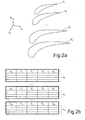
figure 2a is a chart which shows magnitudes used in the present method; -
figure 2b shows the data infigure 2a in table form; -
figure 3 is a flow diagram related to the present method; -
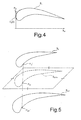
figure 4 is a chart which shows further magnitudes used in the present method; and -
figure 5 is a chart related to a step of the present method.
Infigure 1 , an apparatus for automatically designing turbo-machine blades, specifically gas turbine and steam turbine blades, is indicated byreference number 1. Theapparatus 1 comprises a fluid-dynamic calculation module 2, astructural calculation module 3 and a synthesis module 5.
As shown infigure 2a , the fluid-dynamic calculation module 2, of known type, generates a two-dimensional fluid-dynamic data set FDS, on a plurality of primary blade sections S1, S2, ..., SK (e.g., K = 5), at corresponding distances from the machine axis. The fluid-dynamic data FDS are supplied in the form of tables 6 (figure 2b ) related to a corresponding number of points N1, N2, ..., NK along the profile of each primary blade section S1, S2, ..., SK and comprise, for each point PIJ of the generic primary blade section SJ, Cartesian coordinates XIJ (parallel to the machine axis), YIJ, ZIJ, a temperature value TIJ and a local heat exchange coefficient value HIJ.
Thestructural calculation module 3, also of known type, generates a structural data set SDS in form of a three-dimensional grid of points, which represent the structure and the mechanical features of the blade being studied. Specifically, the structural data SDS allow to define the mechanical behaviour of the blade in running conditions, once synthesized with the fluid-dynamic data FDS, which are used to define the background conditions.
The fluid-dynamic data FDS and the structural data SDS are supplied to the synthesis module 5, which associates corresponding temperature and local heat exchange values starting from the fluid-dynamic data FDS to points of the three-dimensional structural grid defined by the structural data SDS, as shown infigure 3 and explained below. Specifically, reference will be made to a generic primary blade section SJ, meaning the same procedure is also applied to all the others.
A curvilinear coordinate CJ(I) normalized along its profile (Cf. alsofigure 4 ) is initially defined for the primary blade section SJ. More in detail, the point PIJ of the profile of primary blade section SJ having minimum coordinate XIJ is identified and chosen as origin CJ(0) for the curvilinear coordinate CJ(I) (block 100). Then, points PIJ+ belonging to the throat or pressure face of the primary blade section SJ and points PIJ- belonging to the back or suction face of the primary blade section SJ itself are identified and aggregated (block 110).
The curvilinear coordinate CJ(I) is then defined according to the relation (block 120):
- In this step, the number of throat points NJ+ and the number of back points NJ- are counted and stored (such numbers are neither necessarily equal to one another, nor equal for all sections; block 130).
- After having defined the curvilinear coordinate CJ(I) for all the primary blade sections S1, S2, ..., SK, a maximum number of throat points N+ and a maximum number of back points N- (block 140) are selected from the previously stored throat points numbers NJ+ and the previously stored back points numbers NJ- and interpolations are performed to uniform the number and the distribution of the points PIJ on all the primary blade sections S1, S2, ..., SK.
- In practice, N+ throat points PIJ+ and N- back points PIJ- are selected for each primary blade section S1, S2, ..., SK. On each primary blade section S1, S2, ..., SK, the selected throat points PIJ+ have the same curvilinear coordinate values CJ(I) as the throat points PIJ+ of the primary blade section S1, S2, ..., SK having the maximum number of throat points N+; and the back points PIJ- have the same curvilinear coordinate values CJ(I) as the back points PIJ- of the primary blade section S1, S2, ..., SK having the maximum number of back points N-. In this manner, the same number of throat points PIJ+ and back points PIJ- is identified on each primary blade section. Furthermore, the distribution of the points on the various primary blade sections S1, S2, ..., SK is the same. Points of different primary blade sections S1, S2, ..., SK defined by equal curvilinear coordinate values CJ(I) will be indicated hereinafter as homologous.
- Therefore, the Cartesian coordinates XIJ, YIJ, the temperature values TIJ and the heat exchange coefficient values HIJ are determined by interpolation for all the homologous points PIJ' defined by the modified curvilinear coordinate CJ(I) for each primary blade section S1, S2, ..., SK (block 150). Cubic spline type interpolation functions are used for this purpose. Furthermore, on the primary blade sections S1, S2, ..., SK, the interpolation is performed starting from points PIJ selected in the fluid-dynamic data FDS and thus having known features (e.g. the minimum coordinate points XIJ of each primary blade section S1, S2, ..., SK, which define the origin of the curvilinear coordinates).
- Subsequently, an interpolated fluid-dynamic data set FDS' is generated (block 160). More in detail, interpolated blade sections SINTH are generated, interposed in equal number between corresponding pairs of primary blade sections S1, S2, ..., SK so that the distance in radial direction between adjacent sections is constant. For example, between each pair of primary blade sections S1, S2, ..., SK there are interposed 20 equidistant interpolated blade sections SINTH, each of which includes N+ throat points and N- back points, defined by the curvilinear coordinate CJ(I). Therefore, also the interpolated blade sections SINTH have the same number and the same point distribution as the primary blade sections S1, S2, ..., SK. More in detail, Cartesian coordinates XIH, YIH, ZIH of interpolated points PIH of each interpolated blade section SINTH are determined by the intersection between the plane on which the interpolated blade section SINTH lays and lines joining pairs of homologous points PIJ' of adjacent primary blade sections S1, S2, ..., SK (see in this regard
figure 5 ). In practice, all the interpolated points PIH have homologous points PIJ, defined by equal values of the curvilinear coordinate CJ(I), on the primary blade sections S1, S2, ..., SK. Furthermore, temperature values TIH and heat exchange coefficient values HIH which are determined by linear interpolation starting from the temperature values TIJ and the heat exchange coefficient values HIJ of the homologous points PIJ' of the adjacent primary blade sections S1, S2, ..., SK are associated to the interpolated points PIH. Preferably, the interpolation is weighed according to the distance between the interpolated blade section SINTH and the adjacent primary blade sections S1, S2, ..., SK. - Alternatively to the interpolation by joining lines and to weighed linear interpolation, in an embodiment of the invention, an interpolation by spline-type functions, e.g. cubic, is performed.
- At this point, the synthesis module 5 has processed a modified fluid-dynamic data set FDS" which includes fluid-dynamic data FDS and interpolated fluid-dynamic data FDS'. With respect to the fluid-dynamic data FDS initially supplied by the fluid-
dynamic calculation module 3, the modified fluid-dynamic data FDS" present a higher density, are homogenous and define a three-dimensional fluid-dynamic grid. For the sake of simplicity, the points of the fluid-dynamic grid will be thereinafter indicated by PF, regardless of whether they are points PIJ of primary blade sections S1, S2, ..., SK or interpolated points PIH of interpolated blade sections SINTH. - After, the synthesis module 5 defines background conditions for each point of the structural grid defined by the structural data SDS, according to the modified fluid-dynamic data FDS" (block 170). In practice, the temperature value TSIJ and the thermal exchange coefficient value HSIJ of the closest point PF of the fluid-dynamic grid (i.e. having minimum Euclidean distance) are associated to each point of the structural grid, generically indicated by PS and defined by Cartesian coordinates XIS, YIS, ZIS.
- The points PS of the structural grid and of the corresponding temperature values TSIJ and heat exchange coefficient values HSIJ define a background conditions set BDS, which are returned to the
structural calculation module 3 for calculating the thermo-mechanical stresses which the blade is subjected to, under working conditions (block 180). Specifically, thestructural calculation module 3 generates, in an intrinsically known manner, validation data V related to the expected response of the blade to stresses. - The validation data V are then compared with the corresponding safety ranges to verify the feasibility of the blade (block 185). If the test result is positive, i.e. if the validation data V do not exceed the safety ranges (YES output from block 185), the blade is made (block 190). Otherwise (NO output from block 185), the blade design data are modified, updated fluid-dynamic data FDS and structural data SDS are generated (block 195) and the described procedure is repeated starting from the determination of the curvilinear coordinate CJ(I).
- The method according to the invention is advantageous because it allows to automatically process the fluid-dynamic data and to associate them to structural data for calculating thermo-mechanical stresses. Furthermore, the higher density of the fluid-dynamic data may be chosen in the most convenient manner, so as not to produce significant errors with the necessary approximations and to concurrently contain the required computing load. Specifically, the method allows to thoroughly and accurately define the temperature value gradients and the local heat exchange coefficient value gradients on the entire blade surface, avoiding gross approximations. The data transfer from the fluid-dynamic environment to the structural environment may thus occur extremely rapidly and with a very low error margin. The described method is moreover flexible and equally suitable to be employed for designing rotor and stator blades of gas and steam turbines, as well as of compressors.
- It is finally apparent that changes and variations may be made to the described method without departing from the scope of the present invention, as defined in the appended claims. Specifically, it is apparent that other interpolating functions different from those indicated above (cubic spline) may be used to obtain the higher density of the points on the primary blade sections. Furthermore, the number of points on each section may be chosen arbitrarily.
- The interpolated blade sections comprised between two adjacent primary blade sections may be arranged with variable pitch instead of being reciprocally equidistant.
Claims (12)
- A method for designing turbo-machine blades comprising:determining primary fluid-dynamic data (FDS) related to a plurality of first blade sections (S1, S2, ..., SK);determining structural data (SDS); andcorrelating fluid-dynamic data (FDS) to corresponding structural data (SDS);characterized in that correlating fluid-dynamic data (FDS) to corresponding structural data (SDS) comprises:determining interpolated fluid-dynamic data (FDS'), related to a plurality of second blade sections (SINTH) interposed between corresponding first blade sections (S1, S2, ..., SK), starting from the primary fluid-dynamic data (FDS);defining a modified fluid-dynamic data set (FDS"), including primary fluid-dynamic data (FDS) and interpolated fluid-dynamic data (FDS'); andassociating modified fluid-dynamic data (FDS") to corresponding structural data (SDS).
- A method according to claim 1, wherein the modified fluid-dynamic data comprise:coordinates of a plurality of first points (PF) of the first blade sections (S1, S2, ..., SK) and of the second blade sections (SINTH);temperature values (TIJ, TIH), associated to corresponding first points (PF); andheat exchange coefficient values (HIJ, HIH), associated to corresponding first points (PF).
- A method according to claim 2, wherein the structural data (SDS) comprise coordinates of a plurality of second points (PS).
- A method according to claim 3, wherein determining interpolated fluid-dynamic data (FDS') comprises:defining a normalized curvilinear coordinate (CJ(I)) for each first blade section (S1, S2, ..., SK);determining sets of first homologous points (PIJ') having values equal to the normalized curvilinear coordinate (CJ(I)) between the first points (PF) of the first blade sections (S1, S2, ..., SK),; anddetermining corresponding coordinates (XIJ, YIJ, ZIJ), corresponding temperature values (TIJ, TIJ) and corresponding heat exchange coefficient values (HIJ) for the first homologous points (PIJ').
- A method according to claim 4, wherein determining sets of first homologous points (PIJ') comprises:determining a number of throat points (NJ+) and a number of back points (NJ-) for each first blade section (S1, S2, ..., SK);identifying a maximum number of throat points (N+) and a maximum number of back points (N-) between the numbers of throat points (NJ+) and the number of back points (NJ-);selecting, on each first blade section (S1, S2, ..., SK), first homologous points (PIJ') having values of the normalized curvilinear coordinate (CJ(I)) equal to corresponding first throat points (PIJ+) of the first blade section (S1, S2, ..., SK) with the maximum number of throat points (N+) and to corresponding first back points (PIJ-) of the first blade section (S1, S2, ..., SK) having the maximum number of back points (NJ-).
- A method according to claim 5, wherein determining first homologous point sets (PIJ') further comprises performing interpolations starting from the fluid-dynamic data (FDS) and from corresponding values of the normalized curvilinear coordinate (CJ(I)).
- A method according to claim 6, wherein performing interpolations comprises using spline type interpolating functions.
- A method according to any claim from 4 to 7, wherein determining interpolated fluid-dynamic data (FDS') comprises determining a plurality of first interpolated points (PIH) of the second blade sections (SINTH) by interpolation, starting from corresponding first homologous point sets (PIJ').
- A method according to claim 8, wherein determining interpolated fluid-dynamic data (FDS') comprises associating interpolated temperature values (TIH) and interpolated heat exchange coefficient values (HIH) to corresponding first interpolated points (PIH), according to temperature values (TIJ) and heat exchange coefficient values (HIJ) associated to first homologous points (PIJ').
- A method according to claim 8 or 9, wherein the second blade sections (SINTH) are reciprocally equidistant.
- A method according to any claim from 3 to 10, wherein associating modified fluid-dynamic data (FDS") to corresponding structural data (SDS) comprises associating to second points (PS) temperature values (TIJ, TIH) and heat exchange coefficient values (HIJ, HIH) of corresponding first points (PF) having minimum Euclidean distance from the second points (PS).
- An apparatus for automatically designing turbo-machine blades, comprising processing means (2, 3, 5) configured to implement the method according to any of the preceding claims.
Priority Applications (2)
| Application Number | Priority Date | Filing Date | Title |
|---|---|---|---|
| EP07425485A EP2020638A1 (en) | 2007-07-30 | 2007-07-30 | Method for designing turbo-machine blades, specifically gas turbine and steam turbine blades |
| PCT/EP2008/060028 WO2009016210A1 (en) | 2007-07-30 | 2008-07-30 | Method for designing turbo-machine blades, specifically gas turbine and steam turbine blades |
Applications Claiming Priority (1)
| Application Number | Priority Date | Filing Date | Title |
|---|---|---|---|
| EP07425485A EP2020638A1 (en) | 2007-07-30 | 2007-07-30 | Method for designing turbo-machine blades, specifically gas turbine and steam turbine blades |
Publications (2)
| Publication Number | Publication Date |
|---|---|
| EP2020638A1 true EP2020638A1 (en) | 2009-02-04 |
| EP2020638A8 EP2020638A8 (en) | 2009-10-21 |
Family
ID=39494964
Family Applications (1)
| Application Number | Title | Priority Date | Filing Date |
|---|---|---|---|
| EP07425485A Withdrawn EP2020638A1 (en) | 2007-07-30 | 2007-07-30 | Method for designing turbo-machine blades, specifically gas turbine and steam turbine blades |
Country Status (2)
| Country | Link |
|---|---|
| EP (1) | EP2020638A1 (en) |
| WO (1) | WO2009016210A1 (en) |
Cited By (2)
| Publication number | Priority date | Publication date | Assignee | Title |
|---|---|---|---|---|
| EP2602050A1 (en) * | 2011-12-08 | 2013-06-12 | Rolls-Royce Deutschland Ltd & Co KG | Method for selecting a blade geometry |
| EP3693570A1 (en) * | 2019-02-07 | 2020-08-12 | Honeywell International Inc. | Multistage axial-centrifugal compressor systems and methods for manufacture |
-
2007
- 2007-07-30 EP EP07425485A patent/EP2020638A1/en not_active Withdrawn
-
2008
- 2008-07-30 WO PCT/EP2008/060028 patent/WO2009016210A1/en not_active Ceased
Non-Patent Citations (3)
| Title |
|---|
| KAMAKOTI R ET AL: "Fluid-structure interaction for aeroelastic applications", PROGRESS IN AEROSPACE SCIENCES, OXFORD, GB, vol. 40, no. 8, 1 November 2004 (2004-11-01), pages 535 - 558, XP004809381, ISSN: 0376-0421 * |
| KORAKIANITIS T ET AL: "IMPROVED TURBINE-BLADE DESIGN TECHNIQUES USING 4TH-ORDER PARAMETRIC-SPLINE SEGMENTS", COMPUTER AIDED DESIGN, ELSEVIER PUBLISHERS BV., BARKING, GB, vol. 25, no. 5, 1 May 1993 (1993-05-01), pages 289 - 299, XP000943653, ISSN: 0010-4485 * |
| LI ET AL: "Turbine blade temperature transfer using the load surface method", COMPUTER AIDED DESIGN, ELSEVIER PUBLISHERS BV., BARKING, GB, vol. 39, no. 6, 17 May 2007 (2007-05-17), pages 494 - 505, XP022082375, ISSN: 0010-4485 * |
Cited By (4)
| Publication number | Priority date | Publication date | Assignee | Title |
|---|---|---|---|---|
| EP2602050A1 (en) * | 2011-12-08 | 2013-06-12 | Rolls-Royce Deutschland Ltd & Co KG | Method for selecting a blade geometry |
| US9180560B2 (en) | 2011-12-08 | 2015-11-10 | Rolls-Royce Deutschland Ltd & Co Kg | Method for selecting a geometry of a blade |
| EP3693570A1 (en) * | 2019-02-07 | 2020-08-12 | Honeywell International Inc. | Multistage axial-centrifugal compressor systems and methods for manufacture |
| US11156092B2 (en) | 2019-02-07 | 2021-10-26 | Honeywell International Inc. | Multistage axial-centrifugal compressor systems and methods for manufacture |
Also Published As
| Publication number | Publication date |
|---|---|
| WO2009016210A1 (en) | 2009-02-05 |
| EP2020638A8 (en) | 2009-10-21 |
Similar Documents
| Publication | Publication Date | Title |
|---|---|---|
| JP5292477B2 (en) | Diagnostic device and diagnostic method | |
| Kasaei et al. | An application of Quality Function Deployment method in engineering materials selection | |
| US20080221835A1 (en) | Process and methodology for root cause identification in gas turbine engine performance tracking | |
| CN108733889B (en) | Turbine assembly method, turbine assembly auxiliary system, and computer storage medium | |
| CN115356121B (en) | A method for evaluating the life and remaining life damage of turbine blades under service environment | |
| EP1326008A1 (en) | Method and apparatus for assessing performance of combined cycle power-plants | |
| US20070203669A1 (en) | Performance monitoring method and system for a single shaft combined cycle plant | |
| KR20130098179A (en) | Turbo-machinery stage families tuning/calibration system and method | |
| Kraft et al. | Optimization of aero gas turbine maintenance using advanced simulation and diagnostic methods | |
| JP6416610B2 (en) | Plant equipment maintenance planning system and method | |
| CN118898144B (en) | Part life assessment method and system based on transient load, electronic equipment, and storage medium | |
| CN108073145A (en) | Operation support device and program | |
| US10168306B2 (en) | Time reference derivation from time of arrival measurements | |
| EP2135145A1 (en) | Analysis method based on an error function optimization technique | |
| EP2020638A1 (en) | Method for designing turbo-machine blades, specifically gas turbine and steam turbine blades | |
| Blinov et al. | Estimation of the driven gas turbine unit technical performance using the standard measuring systems | |
| US20050038817A1 (en) | System and method for processing inspection data for evaluating degradation of coating on components | |
| US7890296B2 (en) | Method of analyzing the performance of gas turbine engines | |
| Zaccaria et al. | A model-based solution for gas turbine diagnostics: Simulations and experimental verification | |
| Haldeman et al. | Fully cooled single stage HP transonic turbine—Part I: Influence of cooling mass flow variations and inlet temperature profiles on blade internal and external aerodynamics | |
| Kurstak et al. | A statistical characterization of the effects and interactions of small and large mistuning on multistage bladed disks | |
| Ridaura | Correlation analysis between HPC blade chord and compressor efficiency for the CFM56-3 | |
| JP2019157832A (en) | Repair determination device for gas turbine stationary blade and repair determination method for gas turbine stationary blade | |
| US11905892B2 (en) | Flow machine performance modelling | |
| KR20150019360A (en) | Method for evaluating age effect of low pressure turbine |
Legal Events
| Date | Code | Title | Description |
|---|---|---|---|
| PUAI | Public reference made under article 153(3) epc to a published international application that has entered the european phase |
Free format text: ORIGINAL CODE: 0009012 |
|
| AK | Designated contracting states |
Kind code of ref document: A1 Designated state(s): AT BE BG CH CY CZ DE DK EE ES FI FR GB GR HU IE IS IT LI LT LU LV MC MT NL PL PT RO SE SI SK TR |
|
| AX | Request for extension of the european patent |
Extension state: AL BA HR MK RS |
|
| 17P | Request for examination filed |
Effective date: 20090716 |
|
| 17Q | First examination report despatched |
Effective date: 20090812 |
|
| AKX | Designation fees paid |
Designated state(s): AT BE BG CH CY CZ DE DK EE ES FI FR GB GR HU IE IS IT LI LT LU LV MC MT NL PL PT RO SE SI SK TR |
|
| STAA | Information on the status of an ep patent application or granted ep patent |
Free format text: STATUS: THE APPLICATION IS DEEMED TO BE WITHDRAWN |
|
| 18D | Application deemed to be withdrawn |
Effective date: 20100223 |