EP2020476B1 - Slider element mountable without the use of tools - Google Patents
Slider element mountable without the use of tools Download PDFInfo
- Publication number
- EP2020476B1 EP2020476B1 EP08156004.7A EP08156004A EP2020476B1 EP 2020476 B1 EP2020476 B1 EP 2020476B1 EP 08156004 A EP08156004 A EP 08156004A EP 2020476 B1 EP2020476 B1 EP 2020476B1
- Authority
- EP
- European Patent Office
- Prior art keywords
- slider
- glider
- component according
- housing
- pin
- Prior art date
- Legal status (The legal status is an assumption and is not a legal conclusion. Google has not performed a legal analysis and makes no representation as to the accuracy of the status listed.)
- Not-in-force
Links
Images

Classifications
-
- E—FIXED CONSTRUCTIONS
- E05—LOCKS; KEYS; WINDOW OR DOOR FITTINGS; SAFES
- E05D—HINGES OR SUSPENSION DEVICES FOR DOORS, WINDOWS OR WINGS
- E05D15/00—Suspension arrangements for wings
- E05D15/48—Suspension arrangements for wings allowing alternative movements
- E05D15/52—Suspension arrangements for wings allowing alternative movements for opening about a vertical as well as a horizontal axis
- E05D15/5205—Suspension arrangements for wings allowing alternative movements for opening about a vertical as well as a horizontal axis with horizontally-extending checks
-
- E—FIXED CONSTRUCTIONS
- E05—LOCKS; KEYS; WINDOW OR DOOR FITTINGS; SAFES
- E05D—HINGES OR SUSPENSION DEVICES FOR DOORS, WINDOWS OR WINGS
- E05D15/00—Suspension arrangements for wings
- E05D15/06—Suspension arrangements for wings for wings sliding horizontally more or less in their own plane
- E05D15/10—Suspension arrangements for wings for wings sliding horizontally more or less in their own plane movable out of one plane into a second parallel plane
- E05D15/1005—Suspension arrangements for wings for wings sliding horizontally more or less in their own plane movable out of one plane into a second parallel plane the wing being supported on arms movable in horizontal planes
- E05D15/1013—Suspension arrangements for wings for wings sliding horizontally more or less in their own plane movable out of one plane into a second parallel plane the wing being supported on arms movable in horizontal planes specially adapted for windows
- E05D15/1015—Suspension arrangements for wings for wings sliding horizontally more or less in their own plane movable out of one plane into a second parallel plane the wing being supported on arms movable in horizontal planes specially adapted for windows with an intermediate tilt position
-
- E—FIXED CONSTRUCTIONS
- E05—LOCKS; KEYS; WINDOW OR DOOR FITTINGS; SAFES
- E05D—HINGES OR SUSPENSION DEVICES FOR DOORS, WINDOWS OR WINGS
- E05D5/00—Construction of single parts, e.g. the parts for attachment
- E05D5/10—Pins, sockets or sleeves; Removable pins
- E05D5/12—Securing pins in sockets, movably or not
- E05D5/128—Securing pins in sockets, movably or not the pin having a recess or through-hole engaged by a securing member
-
- E—FIXED CONSTRUCTIONS
- E05—LOCKS; KEYS; WINDOW OR DOOR FITTINGS; SAFES
- E05D—HINGES OR SUSPENSION DEVICES FOR DOORS, WINDOWS OR WINGS
- E05D7/00—Hinges or pivots of special construction
- E05D7/10—Hinges or pivots of special construction to allow easy separation or connection of the parts at the hinge axis
- E05D7/1044—Hinges or pivots of special construction to allow easy separation or connection of the parts at the hinge axis in an axial direction
- E05D7/1055—Hinges or pivots of special construction to allow easy separation or connection of the parts at the hinge axis in an axial direction with snap-fitted pins
-
- E—FIXED CONSTRUCTIONS
- E05—LOCKS; KEYS; WINDOW OR DOOR FITTINGS; SAFES
- E05Y—INDEXING SCHEME RELATING TO HINGES OR OTHER SUSPENSION DEVICES FOR DOORS, WINDOWS OR WINGS AND DEVICES FOR MOVING WINGS INTO OPEN OR CLOSED POSITION, CHECKS FOR WINGS AND WING FITTINGS NOT OTHERWISE PROVIDED FOR, CONCERNED WITH THE FUNCTIONING OF THE WING
- E05Y2201/00—Constructional elements; Accessories therefore
- E05Y2201/40—Motors; Magnets; Springs; Weights; Accessories therefore
- E05Y2201/47—Springs; Spring tensioners
- E05Y2201/474—Compression springs
-
- E—FIXED CONSTRUCTIONS
- E05—LOCKS; KEYS; WINDOW OR DOOR FITTINGS; SAFES
- E05Y—INDEXING SCHEME RELATING TO HINGES OR OTHER SUSPENSION DEVICES FOR DOORS, WINDOWS OR WINGS AND DEVICES FOR MOVING WINGS INTO OPEN OR CLOSED POSITION, CHECKS FOR WINGS AND WING FITTINGS NOT OTHERWISE PROVIDED FOR, CONCERNED WITH THE FUNCTIONING OF THE WING
- E05Y2201/00—Constructional elements; Accessories therefore
- E05Y2201/60—Suspension or transmission members; Accessories therefore
- E05Y2201/622—Suspension or transmission members elements
- E05Y2201/708—Sliders
-
- E—FIXED CONSTRUCTIONS
- E05—LOCKS; KEYS; WINDOW OR DOOR FITTINGS; SAFES
- E05Y—INDEXING SCHEME RELATING TO HINGES OR OTHER SUSPENSION DEVICES FOR DOORS, WINDOWS OR WINGS AND DEVICES FOR MOVING WINGS INTO OPEN OR CLOSED POSITION, CHECKS FOR WINGS AND WING FITTINGS NOT OTHERWISE PROVIDED FOR, CONCERNED WITH THE FUNCTIONING OF THE WING
- E05Y2600/00—Mounting or coupling arrangements for elements provided for in this subclass
- E05Y2600/50—Mounting methods; Positioning
- E05Y2600/52—Toolless
- E05Y2600/53—Snapping
-
- E—FIXED CONSTRUCTIONS
- E05—LOCKS; KEYS; WINDOW OR DOOR FITTINGS; SAFES
- E05Y—INDEXING SCHEME RELATING TO HINGES OR OTHER SUSPENSION DEVICES FOR DOORS, WINDOWS OR WINGS AND DEVICES FOR MOVING WINGS INTO OPEN OR CLOSED POSITION, CHECKS FOR WINGS AND WING FITTINGS NOT OTHERWISE PROVIDED FOR, CONCERNED WITH THE FUNCTIONING OF THE WING
- E05Y2600/00—Mounting or coupling arrangements for elements provided for in this subclass
- E05Y2600/60—Mounting or coupling members; Accessories therefore
- E05Y2600/63—Retainers
-
- E—FIXED CONSTRUCTIONS
- E05—LOCKS; KEYS; WINDOW OR DOOR FITTINGS; SAFES
- E05Y—INDEXING SCHEME RELATING TO HINGES OR OTHER SUSPENSION DEVICES FOR DOORS, WINDOWS OR WINGS AND DEVICES FOR MOVING WINGS INTO OPEN OR CLOSED POSITION, CHECKS FOR WINGS AND WING FITTINGS NOT OTHERWISE PROVIDED FOR, CONCERNED WITH THE FUNCTIONING OF THE WING
- E05Y2900/00—Application of doors, windows, wings or fittings thereof
- E05Y2900/10—Application of doors, windows, wings or fittings thereof for buildings or parts thereof
- E05Y2900/13—Application of doors, windows, wings or fittings thereof for buildings or parts thereof characterised by the type of wing
- E05Y2900/148—Windows
Definitions
- the invention relates to a slider component of the fitting technology.
- the slider member is capable of receiving a pin, in particular such a shearing mandrel of a leg to be stored in a rotatable manner and to locate this, respectively to store it in a rotatable manner and at the same time to keep it locked in the longitudinal / axial direction of the pin.
- Sliders as such as well; They have the property to be guided longitudinally movable due to their cuboid housing in a profiled rail and have a geometrically predetermined shape and size, usually elongated, cuboid, to be absorbed in the rail and to slide longitudinally displaceable can. Hence the name of the slider component.
- the slide component explained there in FIGS. 5 to 7 has a cuboid basic body which is designed in two parts.
- the slider member has a receptacle in which a pin can be accommodated as a pivot pin 17, wherein said pin is part of an upper extension arm.
- the pin is rotatably mounted (in a bearing opening).
- a slide as a locking slide is provided, which is actuated by an eccentric. This causes the locking slide (which is longitudinally slidable in the slider housing) to lock, which rotatably locks the pin in the slider member.
- an asymmetrical keyhole opening is provided, there 21.1, which favors receiving the locking slide after the local figure 7 and store rotatably.
- the DE 20 2005 015 034 discloses a slider for a fitting on which a pin of a Ausstellarmes is rotatably mounted.
- a pin of a Ausstellarmes is rotatably mounted.
- two sections of a holding plate can be held together by tension springs.
- the sections have semicircular cutouts and then surround the pin of the Ausstellarmes.
- the object of the invention is to be able to mount known slider components better, respectively faster and more safely. Therein the invention sees its primary task.
- the object is based on keeping a recorded pin from the fitting technology, in particular such on a training or Abstellarm a fitting for a sliding or Abstellulatel, safe and also reliably rotatable.
- the slider member has for this purpose a bearing opening which is able to receive the pin.
- the bearing opening is the rotatable recording. If the pin is received in the bearing opening, a slider ensures that the pin is fixed, but remains rotatable.
- This slider is movable in the longitudinal direction and has a suitable opening for blocking, which surrounds the pin on an undercut provided there and axially locks in its longitudinal direction.
- the slider itself assumes the blocking position only in the deflected state of a spring arm, which in turn is coupled to the insertion movement of the pin. Only in the deflected state of the spring arm, the slider is longitudinally movable to take the locked position.
- the asymmetrical opening which the slider has is asymmetrical with respect to a transverse plane, but may be quite symmetrical with respect to a longitudinal median plane. Due to the unbalanced to the transverse plane training, the opening has a receiving portion and a locking portion which is able to hold the pin axially locked in the retracted position; this inserted position leads via the release of the spring arm to the longitudinal movement of the slider.
- the blocking element in particular designed as an elongated plate, here has the possibility to be released from a - the pin - rotatable locking position.
- the blocking element is longitudinally displaceably blocked in the locking position, but not by the spring arm or a holding pin arranged on it, but by an elastically yielding blocking, which can be released.
- the blocking element can be released from the blockage position and the pin can be removed from the recess for rotatable recording.
- the pin can also be located again rotatable when it is inserted axially into the bearing recess and thereby releases the blocking element from a biasing position and it is automatically causing the rotational location of the pin causing in the longitudinal direction.
- the housing is elongated and formed substantially cuboid. It has a guiding and sliding property and is made of a material that ensures the sliding property.
- a visible edge is arranged on the slide, which allows it to visibly distinguish the two positions of the slide from the outside.
- the visible edge used for this purpose is initially clearly visible. If the slider has been moved in the longitudinal direction, so either the spring arm has triggered or the slider has the rotatable location of the pin causes the visible edge disappears as the projecting portion of the slider housing, is therefore no longer clearly visible and sunk as part of the housing or at least less prominent ,
- one or more may be provided, preferably at the front and rear edges of the slider housing. These also allow reverse insertion of the slider.
- the slider housing has at least one, preferably two hinge sections arranged on the two end sections of the slider housing, which pivotally support a ceiling wall in relation to the base body of the slider housing.
- the top wall has brackets, which are designed to close the top wall. They are arranged to grip over a respective opposite edge of the base body.
- the closed housing forms a narrow, flat guide, in which the longitudinally displaceable locking element is guided displaceably.
- the guide is a kind of shaft opening.
- the ceiling wall can be interrupted in the longitudinal direction.
- a long and a short spring arm allow the blockage in the securing position, or the provision of the biased state of the open position.
- the open position is aligned with the capacity of the pin.
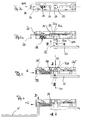
- FIG. 1 The manner of construction of the slider component is best seen from the exploded view of FIG. 1 seen. All other components of a fitting system for sliding leaf or Abstellulatel are not shown here, they do not belong to the Gleiterbauteil, take part only in a cooperating with him function that takes place during assembly of the wing. From fitting part is in the FIGS. 2 to 4 only the front, free end of an arm 10 can be seen, which carries the pin 11, which consists of a lower portion 12, a constriction portion 12a and a head portion 12b.
- This pin is rotatable in the recess 32 of FIG. 1 to store, for which he from the underside of the slider component after FIG. 2b in the local recess as a bearing opening engages while a spring arm 33 entrains in FIG. 1 is shown standing freely in a ceiling wall arranged.
- This spring arm 33 has a front pin 34 and is integrally disposed at one end of the slider member on a remnant piece of the ceiling wall.
- the top wall itself has a second remaining section opposite, which two remaining sections are pivotally connected to the base body 30 of the slider component via hinges 39 ', 39 ".
- the one-piece design thus formed is based on a lubricious material, a plastic, which allows film hinges 39 'and 39' form, in order to open and close the top wall, for the use of a preferably made of metal slide 20, which is also inserted into the main body 30 of the Gleiterbauteils.
- the slider 20 has a contour opening 22 which has a narrower portion 22a and a larger diameter portion. The asymmetry is evident with respect to a transverse plane. The longitudinal plane is aligned along the elongated slide member, ie in the direction of the spring arm 33rd
- the slider 20 as an elongated plate member has a free-standing visible edge 24 which is formed as an angled sheet metal piece. He has a downwardly projecting bend 25, which is able to engage in an elongated space 35a in the main body of the slide member and he has a securing opening 26 near the visible edge 24, which serves for explanatory locking purposes.
- Each of the receiving chambers 35a and 35b can receive a spring 35, here in FIG. 1
- This spring is drawn so that it is inserted into the receiving chamber 35 a to engage the slider 20 with its downwardly projecting bent portion 25 at the right end of the spring 35 and to move the slider to the left to bias the spring 35 and doing so after closing by the top wall (pivoting about the hinges 39 ', 39 ") with engagement of the free pin 34 in the unbalanced opening 22 with its narrower end 22a to fix the slider in the open position.
- This position is the open or ready position (also: basic position), which in the FIGS. 2a, 2b is clarified.
- the slider is ready to receive the pin 11, and has the associated bias by the spring 35, which allows him without tools, and only by engagement of the pin 11 in the recess 32 to achieve a release of this standby position to the pin in Axial direction 100 to lock in rotation.
- This rotatable lock can also be considered as a rotatable locator, in which the pin is longitudinally (axially) located and can not be removed. He remains rotatable.
- the slider 20 is blocked in longitudinal displacement direction. This blocking takes place through the elastically flexible tongue 36 ', or in reverse insertion of the slider 20 as shown FIG. 1 by the blocking lug 36 ", which then engages in the opening 26 as well as in the illustrated illustration of FIG. 3 the spring tab 36 'engages the opening 26. A return movement in the direction of -C is after FIG. 4 initially blocked.
- This position is the holding position.
- the visible edge 24 of the slider 20 is here no longer clearly visible, but became part of the body as a housing, as if they were a wall section of this.
- the holding position is mechanically closed and this closed position is visible visually, relative to the clearly visible protrusion of the visible edge 24 after FIG. 2a ,
- a release of this holding position back to the release position occurs after FIG. 4 , A tool W is for this purpose introduced into a release opening 37 in the direction D, which leads to the spring nose 36 '. This is bent back and on the visible edge 24, the slider 20, for example, be pulled out with the tool W in the direction -C. In this case, the rotatable location of the pin 11 is released, and it can be removed from the bearing opening 32 in the direction -A. This removed state corresponds again to the FIG. 2a When the slider 20 has reached the leftmost position, in which the pin 34 has intervened in the narrower portion 22a of the single-ended opening 22 and again establishes the ready position.
- a movement g takes place from the holding position F to the release position G (F -> g -> G). It arises between the FIGS. 4 and 2a , upon engagement of the tool in the direction D, bending back of the spring lug 36 'and releasing of the slider 20, which can be pulled out in the direction -C along the longitudinal direction 101, so that the visible edge 24 after FIG. 2a again is visible.
- the standby position E is characterized by the slider 20 which is spring-loaded and held by a retaining pin 34 which prevents it from being moved in the longitudinal direction 101.
- the slide is in the deflected state of this holding pin, which is arranged on the spring arm 33, longitudinally movable, in the insertion direction C, which characterizes the movement f.
- the head 12b of the pin 11 inserted into the bearing opening 32 deflects the spring arm 33 in the B direction, which follows FIG. 2b visible to the bearing opening 32 is arranged opposite.
- the holding position F is characterized by the engagement of the asymmetrical opening 22, 22a with its narrower portion around the undercut 12a of the pin. Because the pin 11 does not belong to the slider component here, the holding position F can also be characterized in that the slider 20 has no protruding projecting edge 24 more, it was rather inserted substantially into the outline of the housing 30, and the spring 35 substantially is relieved. Also, this state F can be characterized by a deflection of the spring arm 33, which by spring force in its rest position FIG. 2a pushed back, by concerns on a surface portion of the slider 20 but is prevented.
- the transition state g from the holding position to the release position G is characterized in that the spring lug 36 'is released from its locked position and can be withdrawn in the longitudinal direction 101.
- the wider portion of the opening 22 comes into alignment with the bearing opening 32, so that after pulling out the pin 11 and the spring arm standing under spring force 33 can engage with its retaining pin 34 in the narrower portion 22a of the unbalanced opening and re-lock.
- This release position G preferably again corresponds to the ready position E, which is precisely characterized in that the spring 35 is tensioned and the visible edge 24 protrudes clearly visible.
- the slider component has a top wall that does not run continuously.
- Clamps 40 ', 40 are arranged on two end sections, which are arranged and designed to achieve closing of the top wall above the main body and one positive gripping via one respective opposing edge 42', 42" of the main body.
- a respective bracket 40 ' engages over a respective counter edge 42'.
- the housing 30 In the "closed" state, the housing 30 forms a narrow, shallow shaft opening. It serves to receive and guide the longitudinally displaceable locking element 20 as a slide.
Landscapes
- Engineering & Computer Science (AREA)
- Mechanical Engineering (AREA)
- Connector Housings Or Holding Contact Members (AREA)
- Closing And Opening Devices For Wings, And Checks For Wings (AREA)
- Buckles (AREA)
- Pivots And Pivotal Connections (AREA)
Description
Die Erfindung betrifft ein Gleiterbauteil aus der Beschlagstechnik. Der Gleiterbauteil ist in der Lage, einen Zapfen, insbesondere einen solchen Scherendorn eines drehfähig zu lagernden Armes aufzunehmen und diesen zu lokalisieren, respektive drehfähig zu lagern und gleichzeitig in Längs/Achsrichtung des Zapfens sperrend zu halten.The invention relates to a slider component of the fitting technology. The slider member is capable of receiving a pin, in particular such a shearing mandrel of a leg to be stored in a rotatable manner and to locate this, respectively to store it in a rotatable manner and at the same time to keep it locked in the longitudinal / axial direction of the pin.
Zapfenanordnungen, welche so in einem Gleiterbauteil gehalten und gelagert werden müssen, gibt es in der Beschlagstechnik viele. Gleiter als solche ebenfalls; sie haben die Eigenschaft, aufgrund ihres quaderförmigen Gehäuses in einer profilierten Schiene längsbeweglich geführt werden zu können und haben dafür eine geometrisch vorgegebene Form und Grösse, meist länglich, quaderförmig, um in der Schiene aufgenommen zu werden und darin längsverschieblich gleiten zu können. Daher die Benennung des Gleiterbauteils.Spigot arrangements, which must be kept and stored in a slider component, there are many in the fitting technology. Sliders as such as well; They have the property to be guided longitudinally movable due to their cuboid housing in a profiled rail and have a geometrically predetermined shape and size, usually elongated, cuboid, to be absorbed in the rail and to slide longitudinally displaceable can. Hence the name of the slider component.
Aus der
Die
Es geht der Erfindung darum, bekannte Gleiterbauteile besser, respektive schneller und sicherer montieren zu können. Darin sieht die Erfindung ihre primäre Aufgabe. Zusätzlich liegt die Aufgabe darin begründet, einen aufgenommenen Zapfen aus der Beschlagstechnik, insbesondere einen solchen an einem Aus- oder Abstellarm eines Beschlags für einen Schiebe- oder Abstellflügel, sicher zu halten und auch zuverlässig drehfähig aufzunehmen.The object of the invention is to be able to mount known slider components better, respectively faster and more safely. Therein the invention sees its primary task. In addition, the object is based on keeping a recorded pin from the fitting technology, in particular such on a training or Abstellarm a fitting for a sliding or Abstellflügel, safe and also reliably rotatable.
Die Erfindung erreicht das mit der Lösung nach Anspruch 1.The invention achieves this with the solution according to claim 1.
Das Gleiterbauteil hat dazu eine Lageröffnung, welche in der Lage ist, den Zapfen aufzunehmen. In der Lageröffnung erfolgt die drehfähige Aufnahme. Ist der Zapfen in der Lageröffnung aufgenommen, sorgt ein Schieber dafür, dass der Zapfen fixiert wird, aber drehfähig bleibt. Dieser Schieber ist in Längsrichtung beweglich und weist eine zum Sperren geeignete Öffnung auf, welche den Zapfen an einer dort vorgesehenen Hinterschneidung umgreift und in seiner Längsrichtung axial sperrt.The slider member has for this purpose a bearing opening which is able to receive the pin. In the bearing opening is the rotatable recording. If the pin is received in the bearing opening, a slider ensures that the pin is fixed, but remains rotatable. This slider is movable in the longitudinal direction and has a suitable opening for blocking, which surrounds the pin on an undercut provided there and axially locks in its longitudinal direction.
Der Schieber selbst nimmt die Sperrstellung nur im ausgelenkten Zustand eines Federarms an, der wiederum mit der Einschubbewegung des Zapfens gekoppelt ist. Nur im ausgelenkten Zustand des Federarms ist der Schieber längsbeweglich, um die Sperrstellung einzunehmen.The slider itself assumes the blocking position only in the deflected state of a spring arm, which in turn is coupled to the insertion movement of the pin. Only in the deflected state of the spring arm, the slider is longitudinally movable to take the locked position.
Diese Längsbewegung erfolgt in einer Einschubrichtung, und insoweit ist die Umschreibung des Gleiterbauteils vorgenommen. Ist der Federarm nicht im ausgelenkten Zustand, so kann der Schieber, insbesondere plattenförmig und langgestreckt ausgebildet, nicht in Längsrichtung bewegt werden.This longitudinal movement takes place in an insertion direction, and insofar the description of the Gleiterbauteils is made. If the spring arm is not in the deflected state, then the slider, in particular plate-shaped and elongated, can not be moved in the longitudinal direction.
Die unsymmetrische Öffnung, welche der Schieber aufweist, ist mit Bezug auf eine Querebene unsymmetrisch, kann aber mit Bezug auf eine Längsmittelebene durchaus symmetrisch sein. Aufgrund der zur Querebene unsymmetrischen Ausbildung hat die Öffnung einen Aufnahmeabschnitt und einen Sperrabschnitt, welcher den Zapfen in der eingeschobenen Stellung axial verriegelnd zu halten vermag; wobei diese eingeschobene Stellung über die Auslösung des Federarms zu der Längsbewegung des Schiebers führt.The asymmetrical opening which the slider has is asymmetrical with respect to a transverse plane, but may be quite symmetrical with respect to a longitudinal median plane. Due to the unbalanced to the transverse plane training, the opening has a receiving portion and a locking portion which is able to hold the pin axially locked in the retracted position; this inserted position leads via the release of the spring arm to the longitudinal movement of the slider.
Die zuvor gemachten Ausführungen zur Aufnahme des Zapfens betrifft das Einschieben des Zapfens, nicht sein Herausnehmen. Die zugehörigen Angaben zu Schieber, Federarm und Gleitergehäuse beziehen sich deshalb zunächst auf diesen ersten Funktions- und Bewegungsablauf.The statements made above for receiving the pin relates to the insertion of the pin, not its removal. The corresponding information on slider, spring arm and slider housing therefore initially refer to this first function and movement sequence.
Davon gesondert ist das Lösen des Zapfens zu sehen, welches auf eine andere Methodik zurückgreift. Das Sperrelement, insbesondere ausgebildet als langgestreckte Platte, hat hier die Möglichkeit, aus einer - den Zapfen - drehfähig verriegelnden Stellung gelöst zu werden. Das Sperrelement ist in der Riegelstellung längsverschieblich blockiert, hier aber nicht durch den Federarm oder einen an ihm angeordneten Haltezapfen, sondern durch eine elastisch nachgiebige Blockierung, welche gelöst werden kann. So kann das Sperrelement aus der Blockadestellung gelöst werden und der Zapfen aus der Aussparung zur drehfähigen Aufnahme herausgenommen werden.Separately, the release of the pin can be seen, which uses a different methodology. The blocking element, in particular designed as an elongated plate, here has the possibility to be released from a - the pin - rotatable locking position. The blocking element is longitudinally displaceably blocked in the locking position, but not by the spring arm or a holding pin arranged on it, but by an elastically yielding blocking, which can be released. Thus, the blocking element can be released from the blockage position and the pin can be removed from the recess for rotatable recording.
Der Zapfen kann auch erneut drehfähig lokalisiert werden, wenn er in Richtung axial in die Lageraussparung eingesetzt wird und hierbei das Sperrelement aus einer Vorspannstellung löst und es selbsttätig die drehfähige Lokalisierung des Zapfens bewirkend in Längsrichtung bewegt wird.The pin can also be located again rotatable when it is inserted axially into the bearing recess and thereby releases the blocking element from a biasing position and it is automatically causing the rotational location of the pin causing in the longitudinal direction.
Das Gehäuse ist langgestreckt und im Wesentlichen quaderförmig ausgebildet. Es hat eine Führungs- und Gleiteigenschaft und ist aus einem Werkstoff gefertigt, welcher die Gleiteigenschaft sicherstellt.The housing is elongated and formed substantially cuboid. It has a guiding and sliding property and is made of a material that ensures the sliding property.
Bevorzugt ist an dem Schieber eine Sichtkante angeordnet, welche es von aussen sichtbar die beiden Stellungen des Schiebers zu unterscheiden erlaubt. Die hierzu verwendete Sichtkante steht zunächst deutlich sichtbar hervor. Ist der Schieber in Längsrichtung bewegt worden, wurde also entweder der Federarm ausgelöst oder hat der Schieber die drehfähige Lokalisierung des Zapfens bewirkt, verschwindet die Sichtkante als vorstehender Abschnitt des Gleitergehäuses, ist demnach nicht mehr deutlich sichtbar und als Teil des Gehäuses versenkt oder zumindest weniger vorstehend.Preferably, a visible edge is arranged on the slide, which allows it to visibly distinguish the two positions of the slide from the outside. The visible edge used for this purpose is initially clearly visible. If the slider has been moved in the longitudinal direction, so either the spring arm has triggered or the slider has the rotatable location of the pin causes the visible edge disappears as the projecting portion of the slider housing, is therefore no longer clearly visible and sunk as part of the housing or at least less prominent ,
Von den Sperrnasen, welche den Schieber in der drehfähigen Lokalisierungsstellung halten, können eine oder mehrere vorgesehen sein, bevorzugt am vorderen und hinteren Rand des Gleitergehäuses. Diese erlauben auch ein umgekehrtes Einsetzen des Schiebers.Of the locking lugs which hold the slider in the rotatable locating position, one or more may be provided, preferably at the front and rear edges of the slider housing. These also allow reverse insertion of the slider.
Bevorzugt ist auch, das Gleitergehäuse einstückig auszubilden. Dafür weist das Gleitergehäuse zumindest einen, bevorzugt zwei an den beiden Endabschnitten des Gleitergehäuses angeordnete Scharnierabschnitte auf, welche eine Deckenwand gegenüber dem Grundkörper des Gleitergehäuses schwenkbar lagern.It is also preferable to form the slider housing in one piece. For this purpose, the slider housing has at least one, preferably two hinge sections arranged on the two end sections of the slider housing, which pivotally support a ceiling wall in relation to the base body of the slider housing.
Die Deckwand hat Klammern, welche zum Schliessen der Deckwand ausgebildet sind. Sie sind so angeordnet, über je eine Gegenkante des Grundkörpers zu greifen.The top wall has brackets, which are designed to close the top wall. They are arranged to grip over a respective opposite edge of the base body.
Dieses Greifen erfolgt formschlüssig und hält die Deckwand geschlossen.This gripping takes place positively and keeps the top wall closed.
Das geschlossene Gehäuse bildet eine schmale, flache Führung aus, in der das längsverschiebliche Sperrelement verschieblich geführt ist. Die Führung ist eine Art Schachtöffnung.The closed housing forms a narrow, flat guide, in which the longitudinally displaceable locking element is guided displaceably. The guide is a kind of shaft opening.
Als Abschnitt der Deckenwand kann der Federarm vorgesehen sein. Die Deckenwand kann in Längsrichtung unterbrochen sein.As a section of the ceiling wall of the spring arm may be provided. The ceiling wall can be interrupted in the longitudinal direction.
Ein langer und ein kurzer Federarm ermöglichen die Blockierung in der Sicherungsstellung, oder aber die Vorhaltung des vorgespannten Zustands der Offenstellung. Die Offenstellung ist auf die Aufnahmefähigkeit des Zapfens ausgerichtet.A long and a short spring arm allow the blockage in the securing position, or the provision of the biased state of the open position. The open position is aligned with the capacity of the pin.
Ausführungsbeispiele erläutern und ergänzen die beanspruchte Erfindung.
- Figur 1
- ist eine perspektivische Ansicht eines Gleiterbauteils mit auseinander gezogenen Bauelementen und ohne Darstellung des in der
Aussparung 32 als Lageröffnung aufzunehmenden Zapfens. - Figur 2a
- ist eine Schnittansicht durch die Längsmittelebene eines Gleiterbauteils in zusammengebautem Zustand und in der Bereitschaftsstellung mit einer
herausstehenden Kante 24 des Schiebers 20. DerSchieber 20 ist zur Verdeutlichung kreuzschraffiert dargestellt. - Figur 2b
- ist die Ansicht von unten, aus Sicht eines in die
Ausnehmung 32 als Lageröffnung einzuführenden Zapfens, der hier nicht dargestellt ist, aber denFederarm 33 berühren würde, der gegenüber derLageröffnung 32 sichtbar ist. - Figur 3
- ist eine der Schnittansicht der
Figur 2a entsprechende Darstellung in dem Zustand der drehfähigen Lokalisierung des eingeführten Zapfens 11, dieser gesichert inAchsrichtung 100 gegen ein Lösen durch den Eingriff desSchiebers 20. - Figur 4
- veranschaulicht das Lösen -C des
Schiebers 20 aus der den Zapfen drehfähig lokalisierenden Stellung, durch Einsatz eines Werkzeuges W.
- FIG. 1
- is a perspective view of a slider component with exploded components and without representation of the male in the
recess 32 as a bearing opening to be received pin. - FIG. 2a
- is a sectional view through the longitudinal center plane of a slider member in the assembled state and in the standby position with a protruding
edge 24 of theslider 20. Theslider 20 is shown cross-hatched for clarity. - FIG. 2b
- is the view from below, from the perspective of a in the
recess 32 to be introduced as a bearing opening pin, which is not shown here, but would touch thespring arm 33, which is opposite the bearing opening 32 visible. - FIG. 3
- is a sectional view of
FIG. 2a corresponding representation in the state of the rotational location of the inserted pin 11, this secured in theaxial direction 100 against a release by the engagement of the slider 20th - FIG. 4
- illustrates the release -C of the
slider 20 from the position rotatably locating the pin, by using a tool W.
Die Art und Weise des Aufbaus des Gleiterbauteils wird am besten aus der Explosionsdarstellung der
Dieser Federarm 33 hat einen vorderen Zapfen 34 und ist an einem Ende des Gleiterbauteils an einem Reststück der Deckenwand einstückig angeordnet. Die Deckenwand selbst hat gegenüberliegend einen zweiten Restabschnitt, welche beiden Restabschnitte über Scharniere 39', 39" mit dem Grundkörper 30 des Gleiterbauteils schwenkfähig verbunden sind. Die hier so ausgebildete einstückige Gestaltung basiert auf einem gleitfähigen Werkstoff, einem Kunststoff, der es erlaubt, Filmscharniere 39' und 39" auszubilden, um die Deckwand öffnen und schließen zu können, zum Einsatz eines bevorzugt aus Metall bestehenden Schiebers 20, der ebenfalls in den Grundkörper 30 des Gleiterbauteils eingesetzt wird.This
Der Schieber 20 hat eine Konturöffnung 22, welche einen schmäleren Abschnitt 22a und einen im Durchmesser größeren Abschnitt aufweist. Die Unsymmetrie ist ersichtlich bezüglich einer Querebene. Die Längsebene ist längs des langgestreckten Gleiterbauteils ausgerichtet, also in Richtung des Federarms 33.The
Der Schieber 20 als langgestreckten Plattenbauteil hat eine frei stehende Sichtkante 24, welche als abgewinkeltes Blechstück ausgebildet ist. Er hat eine nach unten ragende Abkröpfung 25, welche in einen langgestreckten Raum 35a im Grundkörper des Gleiterbauteils einzugreifen vermag und er weist eine Sicherungsöffnung 26 nahe der Sichtkante 24 auf, die später zu erläuternden Sperrzwecken dient.The
Am der Sichtkante 24 gegenüberliegenden Ende ist der Schieber anders ausgebildet, um ihn umgekehrt ebenso einsetzen zu können, wenn die nach unten gerichtete Abkröpfung 25 in die zweite Aufnahmekammer 35b eingreifen soll.At the opposite end of the
Jede der Aufnahmekammern 35a und 35b kann eine Feder 35 aufnehmen, hier in
Diese Stellung ist die Offen- oder Bereitschaftsstellung (auch: Grundstellung), welche in den
Ist diese Verriegelungsstellung erreicht, wird der Schieber 20 in Längsverschieberichtung blockiert. Diese Blockierung erfolgt durch die elastisch nachgiebige Zunge 36', oder bei umgekehrten Einsetzen des Schieber 20 gemäß der Darstellung zu
Diese Stellung ist die Haltestellung. Die Sichtkante 24 des Schiebers 20 steht hierbei nicht mehr deutlich sichtbar hervor, sondern wurde zum Bestandteil des Grundkörpers als Gehäuse, wie wenn sie ein Wandabschnitt dieses wäre. Die Haltestellung ist mechanisch verschlossen und diese Schließstellung ist optisch auch sichtbar, relativ zum deutlich sichtbaren Vorstehen der Sichtkante 24 nach
Ein Lösen dieser Haltestellung zurück in die Lösestellung erfolgt nach
Dieser Vorgang kann mehrfach wiederholt werden, so dass sich zwischen der Bereitschaftsstellung, der Haltestellung und der Lösestellung, welche wieder der Bereitschaftsstellung entspricht, ein Zirkel (Umlauf) ergibt, der dadurch besonders einfach ist, dass keine Werkzeuge für die Montage, also für das Erreichen der Haltestellung F nach
- Bereitschaftsstellung E,
- Haltestellung F und
- Lösestellung G
- Ready position E,
- Holding position F and
- Release position G
So eine Bewegung f zwischen der Bereitschaftsstellung E und der Haltestellung E (E -> f -> F), welche der Bewegung von
Eine Bewegung g erfolgt von der Haltestellung F zur Lösestellung G (F -> g -> G). Sie ergibt sich zwischen den
Alle diese Abschnitte sollen eigenständig offenbart sein, sowohl nach ihrer jeweiligen Stellung, wie auch eigenständig offenbart nach ihrem Bewegungsablauf.All these sections should be independently disclosed, both according to their respective position, as well as independently disclosed according to their movement.
Die Bereitschaftsstellung E ist gekennzeichnet durch den Schieber 20, der druckfederbelastet ist und von einem Haltezapfen 34 gehalten wird, der ihn daran hindert in Längsrichtung 101 bewegt zu werden. The standby position E is characterized by the
Der Schieber ist im ausgelenkten Zustand dieses Haltezapfens, der an dem Federarm 33 angeordnet ist, längsbeweglich, und zwar in Einschubrichtung C, welches den Bewegungsablauf f charakterisiert. Damit dieser Bewegungsablauf f in Gang kommt, lenkt der Kopf 12b des in die Lageröffnung 32 eingeschobenen Zapfens 11 den Federarm 33 in B-Richtung aus, der nach
Die Haltestellung F ist charakterisiert durch das Eingreifen der unsymmetrischen Öffnung 22, 22a mit ihrem schmäleren Abschnitt um die Hinterschneidung 12a des Zapfens. Weil der Zapfen 11 hier nicht zum Gleiterbauteil gehört, kann die Haltestellung F auch dadurch charakterisiert werden, dass der Schieber 20 keine abragend vorstehende Sichtkante 24 mehr hat, sie vielmehr im wesentlichen in die Outline des Gehäuses 30 eingeschoben wurde, und die Feder 35 im Wesentlichen entlastet ist. Auch charakterisiert werden kann dieser Zustand F durch ein Auslenken des Federarms 33, der durch Federkraft in seine Ruhestellung nach
Der Übergangszustand g von der Haltestellung zur Lösestellung G ist dadurch charakterisiert, dass die Federnase 36' aus ihrer Sperrstellung gelöst wird und in Längsrichtung 101 zurückgezogen werden kann. Der breitere Abschnitt der Öffnung 22 kommt in Fluchtung mit der Lageröffnung 32, so dass nach Herausziehen des Zapfens 11 auch der unter Federkraft stehende Federarm 33 mit seinem Haltezapfen 34 in den schmäleren Abschnitt 22a der unsymmetrischen Öffnung eingreifen und erneut verriegeln kann.The transition state g from the holding position to the release position G is characterized in that the spring lug 36 'is released from its locked position and can be withdrawn in the
Diese Lösestellung G entspricht bevorzugt erneut der Bereitschaftsstellung E, welche eben dadurch charakterisiert ist, dass die Feder 35 gespannt ist und die Sichtkante 24 deutlich sichtbar hervorsteht. This release position G preferably again corresponds to the ready position E, which is precisely characterized in that the
Das Gleiterbauteil hat eine Deckwand, die nicht durchgehend verläuft. Klammern 40',40" sind daran an zwei Endabschnitten angeordnet. Sie sind so angeordnet und ausgebildet, ein Schließen der Deckwand über dem Grundkörper und je ein formschlüssiges Greifen über je eine Gegenkante 42',42" des Grundkörper zu erreichen. Dazu greift je eine Klammer 40' über je eine Gegenkante 42'.The slider component has a top wall that does not run continuously. Clamps 40 ', 40 "are arranged on two end sections, which are arranged and designed to achieve closing of the top wall above the main body and one positive gripping via one respective opposing
Im Zustand "geschlossen" bildet das Gehäuse 30 eine schmale, flache Schachtöffnung aus. Sie dient der Aufnahme und der Führung des längs-verschieblichen Sperrelements 20 als Schieber.In the "closed" state, the
Claims (9)
- Glider component for receiving a journal (11) of an arm for rotatable mounting thereof in a bearing opening (32), wherein the glider component has(a) a glider housing (30), having the bearing opening (32), and a slider (20) which is longitudinally displaceably guided in the glider housing (30) and ensures that the journal (11) is fixed but remains rotatable, wherein the slider (20) has an asymmetrical opening (22) which is suitable for blocking and which, in the mounted state, engages around the journal (11) on an undercut provided thereon and axially blocks it in its longitudinal direction;characterized in that the glider component has(b) a spring arm (33) which is arranged opposite the bearing opening (32) in order to be deflected when the journal enters;(c) wherein, in the deflected state of the spring arm (33), the slider (20) is longitudinally moveable in an insertion direction (C).
- Glider component according to Claim 1, wherein the slider, loaded with a prestressing force (35), is held in a readiness position by a holding stud (34) which is able to release the slider (20), wherein in particular the holding stud (34) is arranged on the spring arm (33).
- Glider component according to Claim 1, wherein the slider has a visible edge (24) which projects from the glider housing in a clearly visible manner.
- Glider component according to Claim 3, wherein the visible edge (24) is lowered during deflection of the spring arm (33) with the longitudinal movement of the slider in the glider housing, or - while projecting less - becomes a portion of the glider housing.
- Glider component according to Claim 1 or 2, wherein at least one resilient nose (36') is provided which blocks a displacement in the longitudinal movement direction of the slider (20).
- Glider component according to Claim 1 or 2, wherein, with the spring arm (33) deflected, the slider is longitudinally moveable in order to assume the blocking position.
- Glider component according to Claim 1, wherein a glider housing (30) has at least one hinge portion (39', 39") by means of which a cover wall is pivotably arranged on a basic body.
- Glider component according to one of the preceding claims, wherein the slider (20) is blocked in a locking position in the longitudinal displacement direction.
- Glider component according to Claim 8, wherein the blocking is produced by an elastically resilient tongue (36').
Applications Claiming Priority (1)
| Application Number | Priority Date | Filing Date | Title |
|---|---|---|---|
| DE102007022398A DE102007022398B3 (en) | 2007-05-10 | 2007-05-10 | Can be installed without tools |
Publications (4)
| Publication Number | Publication Date |
|---|---|
| EP2020476A2 EP2020476A2 (en) | 2009-02-04 |
| EP2020476A8 EP2020476A8 (en) | 2009-04-22 |
| EP2020476A3 EP2020476A3 (en) | 2014-03-12 |
| EP2020476B1 true EP2020476B1 (en) | 2015-07-29 |
Family
ID=39627741
Family Applications (1)
| Application Number | Title | Priority Date | Filing Date |
|---|---|---|---|
| EP08156004.7A Not-in-force EP2020476B1 (en) | 2007-05-10 | 2008-05-09 | Slider element mountable without the use of tools |
Country Status (2)
| Country | Link |
|---|---|
| EP (1) | EP2020476B1 (en) |
| DE (1) | DE102007022398B3 (en) |
Families Citing this family (1)
| Publication number | Priority date | Publication date | Assignee | Title |
|---|---|---|---|---|
| KR101976931B1 (en) * | 2017-06-26 | 2019-05-09 | 현대자동차주식회사 | Door hinge assembly improving ease of assembly |
Family Cites Families (2)
| Publication number | Priority date | Publication date | Assignee | Title |
|---|---|---|---|---|
| DE202004000610U1 (en) * | 2004-01-15 | 2004-04-29 | Gretsch-Unitas GmbH Baubeschläge | Fitting for an opening and tilting movement of a wing of a building window or a building door as well as a parallel sliding tilt window or door with such a fitting |
| DE202005015034U1 (en) * | 2005-09-22 | 2006-01-19 | Siegenia-Aubi Kg | Slider for a fitting |
-
2007
- 2007-05-10 DE DE102007022398A patent/DE102007022398B3/en not_active Expired - Fee Related
-
2008
- 2008-05-09 EP EP08156004.7A patent/EP2020476B1/en not_active Not-in-force
Also Published As
| Publication number | Publication date |
|---|---|
| EP2020476A3 (en) | 2014-03-12 |
| EP2020476A8 (en) | 2009-04-22 |
| EP2020476A2 (en) | 2009-02-04 |
| DE102007022398B3 (en) | 2008-09-11 |
Similar Documents
| Publication | Publication Date | Title |
|---|---|---|
| DE3612567C2 (en) | ||
| DE4025382C2 (en) | Snap lock with ejection spring | |
| DE69815573T2 (en) | Lock fitting for sliding door, sliding window or the like | |
| DE3815890A1 (en) | REMOTE CONTROLLED LATCH MECHANISM | |
| EP1817983A1 (en) | Device for influencing the movement of furniture parts moving relative to one another and a drawer guide, as well as a method of producing such a device | |
| DE202006012347U1 (en) | Device for locking a furniture part and furniture | |
| DE212020000339U1 (en) | Carrying device for furniture shelves | |
| EP1382098B1 (en) | Electric switch with a drive shaft and a blocking mechanism for blocking actuation of the drive shaft | |
| EP3291702B1 (en) | Piece of furniture and method for fixing a drawer | |
| DE202010007430U1 (en) | Device with an attachment device and drawer | |
| DE3905647C2 (en) | ||
| EP2951374B1 (en) | Running part for guiding a furniture part in a guiding direction via a guiding rail, and furniture fitting | |
| EP2020476B1 (en) | Slider element mountable without the use of tools | |
| DE69811750T2 (en) | Locking fitting for sliding door, sliding window or the like | |
| DE112019007856T5 (en) | COMBINATION LOCK | |
| EP0457170B1 (en) | Hinge | |
| DE3425090C1 (en) | Locking device with at least one bolt or the like. And with a lock for this bolt | |
| EP0199270B1 (en) | Device for keeping a door or window at least ajar | |
| AT514167B1 (en) | locking device | |
| DE3239041A1 (en) | Furniture hinge | |
| DE102007021979B3 (en) | Sliding device for guiding in guide rail fastened to window frame has elastically flexible locking elements which automatically lock locking plate in locking position and in released position automatically block it against displacement | |
| DE3621259A1 (en) | LOCKING DEVICE | |
| EP1421245B1 (en) | Safety device for preventing the incorrect operation of connecting rod fittings | |
| DE102015112004A1 (en) | Guide arrangement for a sliding door, cabinet furniture and method for disassembling a guide assembly for a sliding door | |
| EP3239443B1 (en) | Bearing assembly for a leaf which is pivotable relative to a frame |
Legal Events
| Date | Code | Title | Description |
|---|---|---|---|
| PUAI | Public reference made under article 153(3) epc to a published international application that has entered the european phase |
Free format text: ORIGINAL CODE: 0009012 |
|
| AK | Designated contracting states |
Kind code of ref document: A2 Designated state(s): AT BE BG CH CY CZ DE DK EE ES FI FR GB GR HR HU IE IS IT LI LT LU LV MC MT NL NO PL PT RO SE SI SK TR |
|
| AX | Request for extension of the european patent |
Extension state: AL BA MK RS |
|
| RAP1 | Party data changed (applicant data changed or rights of an application transferred) |
Owner name: HAUTAU GMBH |
|
| RIC1 | Information provided on ipc code assigned before grant |
Ipc: E05D 7/10 20060101AFI20131011BHEP Ipc: E05D 15/52 20060101ALI20131011BHEP |
|
| PUAL | Search report despatched |
Free format text: ORIGINAL CODE: 0009013 |
|
| AK | Designated contracting states |
Kind code of ref document: A3 Designated state(s): AT BE BG CH CY CZ DE DK EE ES FI FR GB GR HR HU IE IS IT LI LT LU LV MC MT NL NO PL PT RO SE SI SK TR |
|
| AX | Request for extension of the european patent |
Extension state: AL BA MK RS |
|
| RIC1 | Information provided on ipc code assigned before grant |
Ipc: E05D 15/52 20060101ALI20140131BHEP Ipc: E05D 7/10 20060101AFI20140131BHEP |
|
| 17P | Request for examination filed |
Effective date: 20140711 |
|
| RBV | Designated contracting states (corrected) |
Designated state(s): AT BE BG CH CY CZ DE DK EE ES FI FR GB GR HR HU IE IS IT LI LT LU LV MC MT NL NO PL PT RO SE SI SK TR |
|
| AKX | Designation fees paid |
Designated state(s): AT BE BG CH CY CZ DE DK EE ES FI FR GB GR HR HU IE IS IT LI LT LU LV MC MT NL NO PL PT RO SE SI SK TR |
|
| REG | Reference to a national code |
Ref country code: DE Ref legal event code: R079 Ref document number: 502008013189 Country of ref document: DE Free format text: PREVIOUS MAIN CLASS: E05D0015000000 Ipc: E05D0007100000 |
|
| GRAP | Despatch of communication of intention to grant a patent |
Free format text: ORIGINAL CODE: EPIDOSNIGR1 |
|
| RIC1 | Information provided on ipc code assigned before grant |
Ipc: E05D 7/10 20060101AFI20150116BHEP Ipc: E05D 15/52 20060101ALI20150116BHEP |
|
| INTG | Intention to grant announced |
Effective date: 20150205 |
|
| GRAS | Grant fee paid |
Free format text: ORIGINAL CODE: EPIDOSNIGR3 |
|
| GRAA | (expected) grant |
Free format text: ORIGINAL CODE: 0009210 |
|
| AK | Designated contracting states |
Kind code of ref document: B1 Designated state(s): AT BE BG CH CY CZ DE DK EE ES FI FR GB GR HR HU IE IS IT LI LT LU LV MC MT NL NO PL PT RO SE SI SK TR |
|
| REG | Reference to a national code |
Ref country code: GB Ref legal event code: FG4D Free format text: NOT ENGLISH |
|
| REG | Reference to a national code |
Ref country code: CH Ref legal event code: EP |
|
| REG | Reference to a national code |
Ref country code: AT Ref legal event code: REF Ref document number: 739437 Country of ref document: AT Kind code of ref document: T Effective date: 20150815 |
|
| REG | Reference to a national code |
Ref country code: IE Ref legal event code: FG4D Free format text: LANGUAGE OF EP DOCUMENT: GERMAN |
|
| REG | Reference to a national code |
Ref country code: DE Ref legal event code: R096 Ref document number: 502008013189 Country of ref document: DE |
|
| REG | Reference to a national code |
Ref country code: LT Ref legal event code: MG4D |
|
| REG | Reference to a national code |
Ref country code: NL Ref legal event code: MP Effective date: 20150729 |
|
| PG25 | Lapsed in a contracting state [announced via postgrant information from national office to epo] |
Ref country code: NO Free format text: LAPSE BECAUSE OF FAILURE TO SUBMIT A TRANSLATION OF THE DESCRIPTION OR TO PAY THE FEE WITHIN THE PRESCRIBED TIME-LIMIT Effective date: 20151029 Ref country code: LV Free format text: LAPSE BECAUSE OF FAILURE TO SUBMIT A TRANSLATION OF THE DESCRIPTION OR TO PAY THE FEE WITHIN THE PRESCRIBED TIME-LIMIT Effective date: 20150729 Ref country code: LT Free format text: LAPSE BECAUSE OF FAILURE TO SUBMIT A TRANSLATION OF THE DESCRIPTION OR TO PAY THE FEE WITHIN THE PRESCRIBED TIME-LIMIT Effective date: 20150729 Ref country code: FI Free format text: LAPSE BECAUSE OF FAILURE TO SUBMIT A TRANSLATION OF THE DESCRIPTION OR TO PAY THE FEE WITHIN THE PRESCRIBED TIME-LIMIT Effective date: 20150729 Ref country code: GR Free format text: LAPSE BECAUSE OF FAILURE TO SUBMIT A TRANSLATION OF THE DESCRIPTION OR TO PAY THE FEE WITHIN THE PRESCRIBED TIME-LIMIT Effective date: 20151030 |
|
| PG25 | Lapsed in a contracting state [announced via postgrant information from national office to epo] |
Ref country code: IS Free format text: LAPSE BECAUSE OF FAILURE TO SUBMIT A TRANSLATION OF THE DESCRIPTION OR TO PAY THE FEE WITHIN THE PRESCRIBED TIME-LIMIT Effective date: 20151129 Ref country code: SE Free format text: LAPSE BECAUSE OF FAILURE TO SUBMIT A TRANSLATION OF THE DESCRIPTION OR TO PAY THE FEE WITHIN THE PRESCRIBED TIME-LIMIT Effective date: 20150729 Ref country code: HR Free format text: LAPSE BECAUSE OF FAILURE TO SUBMIT A TRANSLATION OF THE DESCRIPTION OR TO PAY THE FEE WITHIN THE PRESCRIBED TIME-LIMIT Effective date: 20150729 Ref country code: PT Free format text: LAPSE BECAUSE OF FAILURE TO SUBMIT A TRANSLATION OF THE DESCRIPTION OR TO PAY THE FEE WITHIN THE PRESCRIBED TIME-LIMIT Effective date: 20151130 Ref country code: PL Free format text: LAPSE BECAUSE OF FAILURE TO SUBMIT A TRANSLATION OF THE DESCRIPTION OR TO PAY THE FEE WITHIN THE PRESCRIBED TIME-LIMIT Effective date: 20150729 Ref country code: ES Free format text: LAPSE BECAUSE OF FAILURE TO SUBMIT A TRANSLATION OF THE DESCRIPTION OR TO PAY THE FEE WITHIN THE PRESCRIBED TIME-LIMIT Effective date: 20150729 |
|
| PG25 | Lapsed in a contracting state [announced via postgrant information from national office to epo] |
Ref country code: NL Free format text: LAPSE BECAUSE OF FAILURE TO SUBMIT A TRANSLATION OF THE DESCRIPTION OR TO PAY THE FEE WITHIN THE PRESCRIBED TIME-LIMIT Effective date: 20150729 |
|
| PG25 | Lapsed in a contracting state [announced via postgrant information from national office to epo] |
Ref country code: EE Free format text: LAPSE BECAUSE OF FAILURE TO SUBMIT A TRANSLATION OF THE DESCRIPTION OR TO PAY THE FEE WITHIN THE PRESCRIBED TIME-LIMIT Effective date: 20150729 Ref country code: DK Free format text: LAPSE BECAUSE OF FAILURE TO SUBMIT A TRANSLATION OF THE DESCRIPTION OR TO PAY THE FEE WITHIN THE PRESCRIBED TIME-LIMIT Effective date: 20150729 Ref country code: CZ Free format text: LAPSE BECAUSE OF FAILURE TO SUBMIT A TRANSLATION OF THE DESCRIPTION OR TO PAY THE FEE WITHIN THE PRESCRIBED TIME-LIMIT Effective date: 20150729 Ref country code: SK Free format text: LAPSE BECAUSE OF FAILURE TO SUBMIT A TRANSLATION OF THE DESCRIPTION OR TO PAY THE FEE WITHIN THE PRESCRIBED TIME-LIMIT Effective date: 20150729 |
|
| REG | Reference to a national code |
Ref country code: DE Ref legal event code: R097 Ref document number: 502008013189 Country of ref document: DE |
|
| PG25 | Lapsed in a contracting state [announced via postgrant information from national office to epo] |
Ref country code: RO Free format text: LAPSE BECAUSE OF FAILURE TO SUBMIT A TRANSLATION OF THE DESCRIPTION OR TO PAY THE FEE WITHIN THE PRESCRIBED TIME-LIMIT Effective date: 20150729 |
|
| PLBE | No opposition filed within time limit |
Free format text: ORIGINAL CODE: 0009261 |
|
| STAA | Information on the status of an ep patent application or granted ep patent |
Free format text: STATUS: NO OPPOSITION FILED WITHIN TIME LIMIT |
|
| 26N | No opposition filed |
Effective date: 20160502 |
|
| PG25 | Lapsed in a contracting state [announced via postgrant information from national office to epo] |
Ref country code: BE Free format text: LAPSE BECAUSE OF NON-PAYMENT OF DUE FEES Effective date: 20160531 Ref country code: SI Free format text: LAPSE BECAUSE OF FAILURE TO SUBMIT A TRANSLATION OF THE DESCRIPTION OR TO PAY THE FEE WITHIN THE PRESCRIBED TIME-LIMIT Effective date: 20150729 |
|
| PG25 | Lapsed in a contracting state [announced via postgrant information from national office to epo] |
Ref country code: LU Free format text: LAPSE BECAUSE OF FAILURE TO SUBMIT A TRANSLATION OF THE DESCRIPTION OR TO PAY THE FEE WITHIN THE PRESCRIBED TIME-LIMIT Effective date: 20160509 |
|
| REG | Reference to a national code |
Ref country code: CH Ref legal event code: PL |
|
| GBPC | Gb: european patent ceased through non-payment of renewal fee |
Effective date: 20160509 |
|
| PG25 | Lapsed in a contracting state [announced via postgrant information from national office to epo] |
Ref country code: LI Free format text: LAPSE BECAUSE OF NON-PAYMENT OF DUE FEES Effective date: 20160531 Ref country code: CH Free format text: LAPSE BECAUSE OF NON-PAYMENT OF DUE FEES Effective date: 20160531 |
|
| REG | Reference to a national code |
Ref country code: IE Ref legal event code: MM4A |
|
| REG | Reference to a national code |
Ref country code: FR Ref legal event code: ST Effective date: 20170131 |
|
| PG25 | Lapsed in a contracting state [announced via postgrant information from national office to epo] |
Ref country code: FR Free format text: LAPSE BECAUSE OF NON-PAYMENT OF DUE FEES Effective date: 20160531 |
|
| PG25 | Lapsed in a contracting state [announced via postgrant information from national office to epo] |
Ref country code: IE Free format text: LAPSE BECAUSE OF NON-PAYMENT OF DUE FEES Effective date: 20160509 Ref country code: GB Free format text: LAPSE BECAUSE OF NON-PAYMENT OF DUE FEES Effective date: 20160509 |
|
| PGFP | Annual fee paid to national office [announced via postgrant information from national office to epo] |
Ref country code: IT Payment date: 20170524 Year of fee payment: 10 Ref country code: AT Payment date: 20170519 Year of fee payment: 10 |
|
| PG25 | Lapsed in a contracting state [announced via postgrant information from national office to epo] |
Ref country code: HU Free format text: LAPSE BECAUSE OF FAILURE TO SUBMIT A TRANSLATION OF THE DESCRIPTION OR TO PAY THE FEE WITHIN THE PRESCRIBED TIME-LIMIT; INVALID AB INITIO Effective date: 20080509 Ref country code: CY Free format text: LAPSE BECAUSE OF FAILURE TO SUBMIT A TRANSLATION OF THE DESCRIPTION OR TO PAY THE FEE WITHIN THE PRESCRIBED TIME-LIMIT Effective date: 20150729 |
|
| PG25 | Lapsed in a contracting state [announced via postgrant information from national office to epo] |
Ref country code: MC Free format text: LAPSE BECAUSE OF FAILURE TO SUBMIT A TRANSLATION OF THE DESCRIPTION OR TO PAY THE FEE WITHIN THE PRESCRIBED TIME-LIMIT Effective date: 20150729 Ref country code: MT Free format text: LAPSE BECAUSE OF FAILURE TO SUBMIT A TRANSLATION OF THE DESCRIPTION OR TO PAY THE FEE WITHIN THE PRESCRIBED TIME-LIMIT Effective date: 20150729 |
|
| PG25 | Lapsed in a contracting state [announced via postgrant information from national office to epo] |
Ref country code: BG Free format text: LAPSE BECAUSE OF FAILURE TO SUBMIT A TRANSLATION OF THE DESCRIPTION OR TO PAY THE FEE WITHIN THE PRESCRIBED TIME-LIMIT Effective date: 20150729 |
|
| REG | Reference to a national code |
Ref country code: AT Ref legal event code: MM01 Ref document number: 739437 Country of ref document: AT Kind code of ref document: T Effective date: 20180509 |
|
| PG25 | Lapsed in a contracting state [announced via postgrant information from national office to epo] |
Ref country code: AT Free format text: LAPSE BECAUSE OF NON-PAYMENT OF DUE FEES Effective date: 20180509 |
|
| PG25 | Lapsed in a contracting state [announced via postgrant information from national office to epo] |
Ref country code: IT Free format text: LAPSE BECAUSE OF NON-PAYMENT OF DUE FEES Effective date: 20180509 |
|
| PGFP | Annual fee paid to national office [announced via postgrant information from national office to epo] |
Ref country code: DE Payment date: 20190524 Year of fee payment: 12 |
|
| PGFP | Annual fee paid to national office [announced via postgrant information from national office to epo] |
Ref country code: TR Payment date: 20190429 Year of fee payment: 12 |
|
| REG | Reference to a national code |
Ref country code: DE Ref legal event code: R119 Ref document number: 502008013189 Country of ref document: DE |
|
| PG25 | Lapsed in a contracting state [announced via postgrant information from national office to epo] |
Ref country code: DE Free format text: LAPSE BECAUSE OF NON-PAYMENT OF DUE FEES Effective date: 20201201 |
|
| PG25 | Lapsed in a contracting state [announced via postgrant information from national office to epo] |
Ref country code: TR Free format text: LAPSE BECAUSE OF NON-PAYMENT OF DUE FEES Effective date: 20200509 |