EP2020374B1 - Internal transmission hub assembly - Google Patents
Internal transmission hub assembly Download PDFInfo
- Publication number
- EP2020374B1 EP2020374B1 EP08005620A EP08005620A EP2020374B1 EP 2020374 B1 EP2020374 B1 EP 2020374B1 EP 08005620 A EP08005620 A EP 08005620A EP 08005620 A EP08005620 A EP 08005620A EP 2020374 B1 EP2020374 B1 EP 2020374B1
- Authority
- EP
- European Patent Office
- Prior art keywords
- sleeve
- pawl
- sun gear
- shift
- control
- Prior art date
- Legal status (The legal status is an assumption and is not a legal conclusion. Google has not performed a legal analysis and makes no representation as to the accuracy of the status listed.)
- Active
Links
Images


Classifications
-
- B—PERFORMING OPERATIONS; TRANSPORTING
- B62—LAND VEHICLES FOR TRAVELLING OTHERWISE THAN ON RAILS
- B62M—RIDER PROPULSION OF WHEELED VEHICLES OR SLEDGES; POWERED PROPULSION OF SLEDGES OR SINGLE-TRACK CYCLES; TRANSMISSIONS SPECIALLY ADAPTED FOR SUCH VEHICLES
- B62M11/00—Transmissions characterised by the use of interengaging toothed wheels or frictionally-engaging wheels
- B62M11/04—Transmissions characterised by the use of interengaging toothed wheels or frictionally-engaging wheels of changeable ratio
- B62M11/14—Transmissions characterised by the use of interengaging toothed wheels or frictionally-engaging wheels of changeable ratio with planetary gears
- B62M11/16—Transmissions characterised by the use of interengaging toothed wheels or frictionally-engaging wheels of changeable ratio with planetary gears built in, or adjacent to, the ground-wheel hub
-
- B—PERFORMING OPERATIONS; TRANSPORTING
- B62—LAND VEHICLES FOR TRAVELLING OTHERWISE THAN ON RAILS
- B62M—RIDER PROPULSION OF WHEELED VEHICLES OR SLEDGES; POWERED PROPULSION OF SLEDGES OR SINGLE-TRACK CYCLES; TRANSMISSIONS SPECIALLY ADAPTED FOR SUCH VEHICLES
- B62M11/00—Transmissions characterised by the use of interengaging toothed wheels or frictionally-engaging wheels
- B62M11/04—Transmissions characterised by the use of interengaging toothed wheels or frictionally-engaging wheels of changeable ratio
- B62M11/14—Transmissions characterised by the use of interengaging toothed wheels or frictionally-engaging wheels of changeable ratio with planetary gears
- B62M11/18—Transmissions characterised by the use of interengaging toothed wheels or frictionally-engaging wheels of changeable ratio with planetary gears with a plurality of planetary gear units
Definitions
- This invention generally relates to an internal transmission hub assembly. More specifically, the present invention relates to an internal transmission hub assembly that includes a shift control sleeve (a pawl control member).
- Bicycling is becoming an increasingly more popular form of recreation as well as a means of transportation. Moreover, bicycling has become a very popular competitive sport for both amateurs and professionals. Whether the bicycle is used for recreation, transportation or competition, the bicycle industry is constantly improving the various components of the bicycle. One component that has been extensively redesigned is the bicycle internal transmission hub assembly.
- the internal transmission hub assembly is typically a rear wheel hub that includes an internal gearing mechanism that includes elements that can be shifted to provide a plurality of power transmission paths (gear ratios) for a cyclist.
- a cyclist changes pedaling speeds by manipulating a conventional lever actuating shifting mechanism installed on or adjacent to the handlebars of the bicycle. Movement of the lever actuating shifting mechanism is transmitted to the internal transmission hub assembly by a Bowden-type cable that is operably connected to a shift mechanism within the internal transmission hub assembly. Changes in the position of the lever actuating shifting mechanism cause movement of various elements of the shift mechanism within the internal transmission hub assembly that ultimately determine the selection of a power transmission path (gear ratio).
- the shift mechanism of the internal transmission hub assembly typically includes a shifting key guide, shift control sleeve (a pawl control member) and a sleeve guide.
- the shift control sleeve is pivoted about a stationary hub axle within the internal transmission hub assembly by the various elements of the shift mechanism of the internal transmission hub assembly.
- the shift control sleeve typically includes a base sleeve and one or more arcuately shaped control sleeves.
- the base sleeve typically extends in an axial direction along side a stationary hub axle with a first end and a second end.
- the first end of the base sleeve typically extends through an opening in the shifting key guide.
- no mechanical fastening is provided between the first end of the base sleeve and the shifting key guide.
- the first end of the base sleeve extends through the opening in the shifting key guide. Consequently, the base sleeve is moved is a circumferential direction about the stationary hub axle by rotational movement of the shifting key guide.
- the control sleeves of the shift control sleeve are configured to engage and dis-engage pawls that selectively engage sun gears within the internal transmission hub assembly.
- the pawls act as one-way clutches to selectively stop rotation of the sun gears in one direction.
- the second end of the base sleeve of the shift control sleeve (pawl control member) is confined in a recess formed in a sleeve guide that is also rotatably installed on the stationary hub axle of the internal transmission hub assembly.
- no mechanical fastening is provided between the second end of the base sleeve and the sleeve guide.
- the base sleeve of the pawl control member, the sleeve guide and the shift key guide move about the stationary hub axle as a single unit.
- a problem with the base sleeve of the pawl control member, the sleeve guide and the shift key guide is that there can be minute amounts of play or slight relative movement between these elements. As with any mechanical device, play or slight relative movement between mechanically connected elements is undesirable. Over time, a loose or sloppy feel can be notice by a cyclist when shifting between power transmission path.
- the second end of the base sleeve of the pawl control member is caulked or crimped within the recess of the sleeve guide, thereby initially eliminating play between the base sleeve and the sleeve guide.
- play between the base sleeve and the sleeve guide may develop.
- the configuration disclosed in EP Patent Application Number 1,323,627 does not address the elimination of play between the shift key guide and the base sleeve of the pawl control member.
- One object of the present invention is to provide an internal transmission hub assembly with features that reduce or eliminate play or slight relative movement between elements of the shifting mechanism within the internal transmission hub assembly.
- an internal transmission hub assembly with a stationary hub shaft, a shift control sleeve, a sleeve guide and a shifting key guide.
- the stationary hub shaft is configured to non-rotatably attach to a bicycle frame.
- the stationary hub shaft defines an axis of rotation.
- the shift control sleeve is disposed adjacent to the stationary hub shaft for limited circumferential movement relative to the stationary hub shaft about the axis of rotation.
- the shift control sleeve is also configured to control operation of at least one sun gear disposed about the stationary hub shaft.
- the shift control sleeve includes a base sleeve and at least one pawl control arm.
- the base sleeve further has a first end and a second end.
- the sleeve guide is rotatably disposed about a first portion of the stationary hub shaft.
- the sleeve guide supports the first end of the base sleeve of the shift control sleeve.
- the first end of the base sleeve is welded to the sleeve guide.
- the shifting key guide is rotatably disposed about a second portion of the stationary hub shaft and supports the second end of the base sleeve of the shift control sleeve.
- the second end of the base sleeve is welded to the shifting key guide.
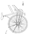
- Figure 1 is a fragmentary side elevation of a bicycle, showing a rear portion of the bicycle with a hub assembly in accordance with the present invention
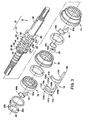
- Figure 2 is a cross-sectional view of the hub assembly showing various portions of the hub assembly including a power transmission assembly with a shift mechanism in accordance with the present invention
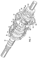
- Figure 3 is an exploded view of a portion of the hub assembly showing elements of the power transmission assembly including a hub axle, a sleeve guide, and a pawl control member with elements of the shift mechanism removed in accordance with the present invention
- Figure 4 is an exploded view of a portion of the hub assembly showing the hub axle and elements of the shift mechanism including the a pawl control member and a shifting key guide in accordance with the present invention
- Figure 5 is a perspective view of a portion of the hub assembly partially assembled showing the hub axle, sun gears and a portion of the pawl control member with other elements removed for clarity in accordance with the present invention
- Figure 6 is another perspective of the portion of the hub assembly similar to Figure 5 with the portion of the hub assembly partially assembled showing the hub axle, the sun gears, a shift key guide and the portion of the pawl control member extending through an opening of the shift key guide with other elements removed for clarity in accordance with the present invention;
- Figure 7 is a perspective view of the portion of the hub assembly similar to Figures 5 and 6 with the portion of the hub assembly partially assembled showing the hub axle, the sun gears and elements of the shift mechanism of the hub assembly in accordance with the present invention
- Figure 8 is another perspective view of a portion of the hub assembly showing the hub axle, the sleeve guide, a first sun gear and the pawl control member of the shift mechanism of the hub assembly with other elements removed to provide greater clarity in accordance with the present invention
- Figure 9 is another perspective view of the portion of the hub assembly from a reverse angle, showing the hub axle, the first sun gear, the shift key guide and the portion of the pawl control member extending through the aperture of the shift key guide with other elements removed to provide greater clarity in accordance with the present invention
- Figure 10 is a side elevational view of the portion of the hub assembly showing the hub axle, the sleeve guide, the first sun gear, the shift key guide and the pawl control member with other elements removed to provide greater clarity in accordance with the present invention
- Figure 11 is a side elevational view of the pawl control member shown removed from the hub assembly showing a base sleeve and first, second and third control sleeves extending from the base sleeve in accordance with the present invention
- Figure 12 is a cross-sectional view of the first control sleeve of the pawl control member taken along the line 12-12 in Figure 11 showing pawl control recesses of the first control sleeve in accordance with the present invention
- Figure 13 is a cross-sectional view of the second control sleeve of the pawl control member taken along the line 13-13 in Figure 11 showing pawl control recesses of the second control sleeve in accordance with the present invention
- Figure 14 is a cross-sectional view of the third control sleeve of the pawl control member taken along the line 14-14 in Figure 11 showing pawl control recesses of the third control sleeve in accordance with the present invention
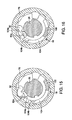
- Figure 15 is a cross-sectional view of a portion of the hub assembly showing the third control sleeve of the pawl control member positioned to allow a pawl to engage an inner set of gear teeth of a third sun gear disposed about the hub shaft such that the pawl acts as a one way clutch preventing the third sun gear from rotating in one direction in accordance with the present invention;
- Figure 16 is another cross-sectional view of the portion of the hub assembly showing the third control sleeve of the pawl control member positioned to prevent the pawl from engaging the inner set of gear teeth of a third sun gear in accordance with the present invention
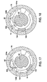
- Figure 17 is yet another cross-sectional view of the portion of the hub assembly showing the third control sleeve of the pawl control member positioned to allow the pawl to engage the inner set of gear teeth of the third sun gear such that the pawl acts as a one way clutch preventing the third sun gear from rotating in one direction in accordance with the present invention
- Figure 18 is still another cross-sectional view of the portion of the hub assembly showing the third control sleeve of the pawl control member in another position that prevents the pawl from engaging the inner set of gear teeth of a third sun gear in accordance with the present invention
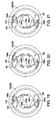
- Figure 19 is a cross sectional view of a shift assist mechanism of the shift mechanism of the hub assembly showing a pair of shift assist pawls in a retracted position urged radially inward by a pair of projection of a pawl control washer in accordance with the present invention
- Figure 20 is another cross sectional view of the shift assist mechanism of the shift mechanism of the hub assembly showing the pair of shift assist pawls in an engaged position contacting a portion of the driver urging the shift mechanism to rotate in accordance with the present invention
- Figure 21 is still another cross sectional view of the shift assist mechanism of the shift mechanism of the hub assembly showing the pair of shift assist pawls being moved from the engaged position back to the retracted position shown in Figure 19 in accordance with the present invention
- Figure 22 is an enlarged portion of the cross-sectional view of Figure 2 , showing a portion of the hub assembly with a clutch ring in dis-engaged with the first sun gear of the hub assembly in accordance with the present invention
- Figure 23 is a cross-sectional view similar to Figure 22 , showing a portion of the hub assembly with the clutch ring engaged from the first sun gear of the hub assembly in accordance with the first embodiment of the present invention
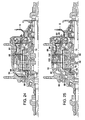
- Figure 24 is a cross-sectional view of a portion of the hub assembly similar to Figure 2 showing a first power transmission path superimposed over those element of the power transmission assembly that define the first power transmission in accordance with the first embodiment of the present invention
- Figure 25 is a cross-sectional view of a portion of the hub assembly similar to Figures 2 and 24 showing a second power transmission path superimposed over those element of the power transmission assembly that define the second power transmission in accordance with the first embodiment of the present invention
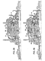
- Figure 26 is a cross-sectional view of a portion of the hub assembly similar to Figure 2 , 24 and 25 showing a third power transmission path superimposed over those element of the power transmission assembly that define the third power transmission in accordance with the first embodiment of the present invention
- Figure 27 is a cross-sectional view of a portion of the hub assembly similar to Figure 2 and 24-26 showing a fourth power transmission path superimposed over those element of the power transmission assembly that define the fourth power transmission in accordance with the first embodiment of the present invention
- Figure 28 is a cross-sectional view of a portion of the hub assembly similar to Figure 2 and 24-27 showing a fifth power transmission path superimposed over those element of the power transmission assembly that define the fifth power transmission in accordance with the first embodiment of the present invention
- Figure 29 is a cross-sectional view of a portion of the hub assembly similar to Figure 2 and 24-28 showing a sixth power transmission path superimposed over those element of the power transmission assembly that define the sixth power transmission in accordance with the first embodiment of the present invention
- Figure 30 is a cross-sectional view of a portion of the hub assembly similar to Figure 2 and 24-29 showing a seventh power transmission path superimposed over those element of the power transmission assembly that define the seventh power transmission in accordance with the first embodiment of the present invention.
- Figure 31 is a cross-sectional view of a portion of the hub assembly similar to Figure 2 and 24-30 showing an eighth power transmission path superimposed over those element of the power transmission assembly that define the eighth power transmission in accordance with the first embodiment of the present invention.
- FIG. 1 a bicycle 10 with a hub assembly 12 is illustrated in accordance with a first embodiment of the present invention.
- the hub assembly 12 includes a power transmission assembly 14 that has a shift mechanism 16 (a shift control mechanism) that controls movement of a pawl control member 18 (see Figures 3-6 and 8-14 ) and a clutch ring 20.
- the pawl control member 18 and the clutch ring 20 are selectively movable to a combination of positions in order to configure various elements of the power transmission assembly 14 to transmit torque along a plurality of power transmission paths indicated in Figure 24-31 and described in greater detail below.
- the shift mechanism 16 of present invention also includes a sleeve guide 22 ( Figures 3 , 5 , 8 and 10 ) and a shifting key guide 24 ( Figures 4 , 6 and 9 ) that support the pawl control member 18 for limited movement to discreet positions corresponding to the power transmission path.
- a sleeve guide 22 Figures 3 , 5 , 8 and 10
- a shifting key guide 24 Figures 4 , 6 and 9
- one end of the pawl control member 18 is welded to the sleeve guide 22 and the other end of the pawl control member 18 is welded to the shifting key guide 24, as described below.
- the hub assembly 12 basically includes a hub axle 26, a driver 28, a hub shell 30, the power transmission assembly 14 and the shift mechanism 16.
- the hub axle 26 is basically an elongated shaft that is non-rotatably mounted to the rear frame of the bicycle 10 in a conventional manner.
- the hub axle 26 includes shift control support portion 32 and a transmission support portion 34.
- the shift control support portion 32 of the hub axle 26 has a generally uniform diameter and includes a pair of axially extending grooves 36 (only one groove 36 visible in Figures 3 and 4 ) formed in a portion thereof.
- the transmission support portion 34 of the hub axle 26 is dimensioned to receive and retain various portions of the power transmission assembly 14.
- the transmission support portion 34 of the hub axle 26 basically includes lobes or protrusions with an overall diameter larger than the outer diameter of the shift control support portion 32.
- the transmission support portion 34 further includes a series of circumferentially extending recesses and axially extending grooves that intersect with one another.
- the transmission support portion 34 includes the following circumferentially extending recesses: a spring retaining recess 40, a first pawl control arm receiving recess 42, a second pawl control arm receiving recess 44, spring receiving recesses 46 and 48 and a third pawl control arm receiving recess 50. Further, the transmission support portion 34 includes the following axially extending grooves: a first locking groove 60, a second locking groove 62, a pawl receiving groove 64 that includes a first, second and third portion 64a, 64b and 64c and a control arm receiving groove 68 that is best shown in Figure 8 . These grooves and recesses of the transmission support portion 34 receive elements the power transmission assembly 14, as described below.
- the driver 28 is rotatably supported about the hub axle 26 in a conventional manner by conventional bearings B 1 and the hub shell 30 is rotatably supported to the hub axle 26 and the driver 28 in a conventional manner by conventional bearings B 2 and B 3 .
- the driver 28 can be selectively coupled to the hub shell 30 by the power transmission assembly 14 such that torque applied to the driver 28 is transmitted to the hub shell 30 in any one of a plurality of selected power transmission paths described below.
- the hub shell 30 includes first torque transmission gear teeth 30a (right side of Figure 2 ) and second torque transmission gear teeth 30b (left side of Figure 2 , whose function is described in greater detail below.
- the power transmission assembly 14 is a multispeed internal hub transmission.
- the power transmission assembly 14 basically includes (among other things) the pawl control member 18 ( Figure 3 ), the clutch ring 20 ( Figure 2 ), a ring shaped shift key member 70 ( Figures 2 and 4 ), the sleeve guide 22 ( Figure 2-3 ), the driver 28 ( Figure 2 ), a first sun gear 72 ( Figure 2 ), a second sun gear 74, a third sun gear 76, a fourth sun gear 78, a second sun gear pawl 80, a third sun gear pawl 82, a fourth sun gear pawl 84, a planet gear carrier 86 ( Figure 2 ), a first set of planet gears 88 ( Figure 2 ), a second set of planet gears 90 ( Figure 2 ), a pawl 92 ( Figure 2 ), a first ring gear 94 ( Figure 2 ), a second ring gear 96 ( Figure 2 ), a pawl 98 ( Figure 2 ),
- the pawl control member 18 is a shift control sleeve that basically includes a base sleeve 100, a first control sleeve 102, a second control sleeve 104 and a third control sleeve 106.
- the base sleeve 100 is an elongated straight portion that extends approximately the length of the transmission support portion 34 of the hub axle 26.
- the base sleeve 100 is an elongated flat bar-like portion includes a first end 108 and a second end 110.
- the base sleeve 100 is disposed within the control arm receiving groove 68 of the transmission support portion 34 of the hub axle 26; the first control sleeve 102 is disposed within the first pawl control arm receiving recess 42; the second control sleeve 104 is disposed within the second pawl control arm receiving recess 44; and the third control sleeve 106 is disposed within the third pawl control arm receiving recess 50.
- the first control sleeve 102, the first pawl control arm receiving recess 42, the second control sleeve 104, the second pawl control arm receiving recess 44, the third control sleeve 106 and the third pawl control arm receiving recess 50 act as bearing surfaces. More specifically, the first control sleeve 102 is circumferentially slidable within the first pawl control arm receiving recess 42; the second control sleeve 104 is circumferentially slidable within the second pawl control arm receiving recess 44; and the third control sleeve 106 is circumferentially slidable within the third pawl control arm receiving recess 50.
- the circumferential movement is limited mainly by the base sleeve 100 contacting the surfaces on either circumferential side 68a and 68b of the control arm receiving groove 68, as indicated in Figure 8 .
- the first control sleeve 102 of the pawl control member 18 includes pawl control recesses 102a and 102b. With the hub assembly 12 fully assembled, the first control sleeve 102 is disposed within the first pawl control arm receiving recess 42 of the hub axle 26, as shown in Figure 10 .
- the pawl control recesses 102a and 102b are dimensioned to interact with a projection 84a of the fourth sun gear pawl 84.
- the projection 84a of the fourth sun gear pawl 84 can move into one or the other of the pawl control recesses 102a and 102b and the fourth sun gear pawl 84 moves radially outward.
- the fourth sun gear pawl 84 engages an inner surface of the fourth sun gear 78 such that the fourth sun gear 78 no longer rotates relative to the hub axle 26 in one direction.
- the operation of the first control sleeve 102 is similar to operation of the second and third control sleeves 104 and 106.
- the following description of the second control sleeve 104 and Figures 15-18 also applies to both the first control sleeve 102 and the third control sleeve 106.
- the second control sleeve 104 of the pawl control member 18 includes pawl control recesses 104a and 104b. With the hub assembly 12 fully assembled, the second control sleeve 104 is disposed within the second pawl control arm receiving recess 44 of the hub axle 26, as shown in Figure 10 .
- the pawl control recesses 104a and 104b are dimensioned to interact with a projection 82a of the third sun gear pawl 82.
- the projection 82a of the third sun gear pawl 82 can move into one or the other of the pawl control recesses 104a and 104b and the third sun gear pawl 82 moves radially outward, as shown in Figures 15 and 17 .
- the third sun gear pawl 82 engages an inner surface of the third sun gear 76 such that the third sun gear 76 is prevented from rotating relative to the hub axle 26 in one direction.
- the third sun gear pawl 82 acts as a one-way clutch allowing the third sun gear 76 to rotate in only one direction.
- the projection 82a contacts other portions of the second control sleeve 104 the third sun gear pawl 82 is urged inward and the third sun gear 76 can rotate freely in both directions about the hub axle 26.
- the third control sleeve 106 of the pawl control member 18 includes pawl control recesses 106a and 106b. With the hub assembly 12 fully assembled, the third control sleeve 106 is disposed within the third pawl control arm receiving recess 50 of the hub axle 26.
- the pawl control recesses 106a and 106b are dimensioned to interact with a projection 80a of the second sun gear pawl 80.
- the projection 80a of the second sun gear pawl 80 can move into one or the other of the pawl control recesses 106a and 106b and the second sun gear pawl 80 moves radially outward.
- the second sun gear pawl 80 engages an inner surface of the second sun gear 74 such that the second sun gear 74 is prevented from rotating relative to the hub axle 26 in one direction.
- the positioning of the pawl control member 18 determines which power transmission path or gear ratio is engaged within the hub assembly 12.
- there are eight power transmission paths (described below). It should be understood from the drawings and description herein that the present invention can be used with hub assemblies having any of a variety of power transmission paths and is not limited to use with a hub assembly having eight power transmission paths. For example, the present invention can be used in a hub assembly having just two power transmission paths or more, 10 or more power transmission paths.
- the clutch ring 20 is an annular member with a first set of gear teeth 120 on an outer periphery thereof and a second set of gear teeth 122 at an axial end thereof.
- An inner peripheral surface of the clutch ring 20 includes a retaining clip 124 and a radially inward extending portion 126.
- the shift key member 70 is axially confined between the retaining clip 124 and the radially inward extending portion 126, as best shown in Figures 22 and 23 .
- the clutch ring 20 is disposed radially inward from the hub shell 30 and the driver 28 and radially outward from the shift mechanism 16.
- the clutch ring 20 can undergo limited movement in an axial direction relative to the hub axle 26 and is rotatable about the hub axle 26, as indicated in Figures 22 and 23 .
- the sleeve guide 22 has an annular disk shape with a central aperture 22a, a first recess 22b and a second recess 22c.
- the central aperture 22a is dimensioned to receive a portion of the transmission support portion 34 of the hub axle 26, as indicated in Figure 8 .
- the sleeve guide 22 is rotatably disposed about the hub axle 26.
- the second recess 22c of the sleeve guide 22 is shaped and dimensioned to the second end 110 of the pawl control member 18. More specifically, the second end 110 of the base sleeve 100 is shaped to fit into the second recess 22c of the sleeve guide 22.
- the second end 110 when the second end 110 is inserted into the second recess 22c of the sleeve guide 22, the second end 108 is welded to the sleeve guide 22 to ensure a rigid fixed attachment. Hence, there is no play or relative movement between the sleeve guide 22 and the pawl control member 18.
- the driver 28 is a generally annular member with several differing diameter portions that is rotatably supported about the hub axle 26 by the bearings B 1 in a conventional manner.
- the driver 28 further supports the bearings B 3 that support the hub shell 30.
- the driver 28 includes gear teeth 134 ( Figures 22 and 23 ) on a radially inward surface thereof, a chain sprocket support portion 136 ( Figure 2 only), a pawl engaging portion 138 on a radially outward portion and shift assist gear teeth 140 ( Figures 2 , 19, 20 and 21 ) on a radially inward portion.
- the gear teeth 134 are dimensioned to mesh with the first set of gear teeth 120 of the clutch ring 20 such that the clutch ring 20 always rotates with the driver 28 ( Figures 22 and 23 ).
- the clutch ring 20 is configured to move in an axial direction along the length of the gear teeth 134, as described below.
- the chain sprocket support portion 136 of the driver 28 supports a chain sprocket S that is fixedly attached to the driver 28 for rotation therewith.
- the driver 28, the clutch ring 20 and the chain sprocket S rotate together as a single unit.
- the purpose of the shift assist gear teeth 140 is explained below.
- the clutch ring 20 is movable from a first position shown in Figures 22 and 24-27 to a second position shown in Figures 23 and 28-31 .
- the clutch ring 20 In the first position shown in Figures 22 and 24-27 , the clutch ring 20 is idle and rotates with the driver 28.
- torque from the driver 28 is transmitted to the first ring gear 94 via the pawl 92 in a first group of first power transmission paths depicted in Figures 24-27 , as described in greater detail below.
- the second set of gear teeth 122 of the clutch ring 20 engage and mesh with gear teeth of the plane gear carrier 86 and torque from the driver 28 is transmitted from the driver 28 to the plane gear carrier 86 in a second group of power transmission path depicted in Figures 28-31 , as described in greater detail below.
- the clutch ring 20 is moved between the first and second positions by the shift mechanism 16, as described below.
- the shift key member 70 functions to couple the clutch ring 20 to portions of the shift mechanism 16 for movement of the clutch ring 20 between the first position ( Figures 24 ) and the second position ( Figures 25 ) of the clutch ring 20.
- the shift key member 70 is an annular ring-shaped member and includes a pair of radially inwardly extending cam followers 144.
- the outer annular portion of the shift key member 70 is confined between the retaining clip 124 and the radially inward extending portion 126 of the clutch ring 20.
- the first sun gear 72 is non-rotatably supported on the hub axle 26 in a conventional manner.
- the first sun gear 72 includes radially outwardly extending gear teeth that mesh with small diameter gear teeth on the first set of planet gears 88 in a conventional manner, as indicated in Figure 2 .
- a cam portion 152 is located adjacent to the first sun gear 72.
- the cam portion 152 can be formed as a part of the first sun gear 72 or can be a member separate from the first sun gear 72, as indicated in Figures 2 and 4 .
- the cam portion 152 is non-rotatably installed on the transmission support portion 34 of the hub axle 26.
- the cam portion 152 includes a pair of first cam surfaces 154, second cam surfaces 156 and third cam surfaces 158.
- the cam portion 152 is configured to move the shift key member 70 and the clutch ring 20 between the first and second positions shown in Figures 24 and 25 , as described in greater detail below.
- the shift key member 70 has an inner overall diameter (absent the pair of radially inwardly extending cam followers 144) that is slightly greater than an outer diameter of cam portion 152 of the first sun gear 72. However, the pair of radially inwardly extending cam followers 144 extend radially inward beyond an inner surface of the cam portion 152, as explained further below in the description of the shifting key guide 24.
- the second sun gear 74, the third sun gear 76 and the fourth sun gear 78 are all selectively rotatable relative to the axle 26.
- the second sun gear 74, the third sun gear 76 and the fourth sun gear 78 each have respective conventional internal pawl ratchet teeth and external gear teeth.
- the second sun gear pawl 80 includes a control portion 80a and a spring 80b.
- the control portion 80a of the second sun gear pawl 80 is pivotally retained within the third portion 64c of the recess 64 of the hub axle 26 such that the second sun gear pawl 80 can selectively pivot radially outward and ratchet against the internal pawl ratchet teeth of the second sun gear 74.
- the spring 80b is installed in the spring receiving recess 48 and biases the second sun gear pawl 80 outward.
- the second sun gear pawl 80 remains in position relative to the hub axle 26 and selectively engages the internal ratchet teeth of the second sun gear 74 in response to positioning of the pawl control member 18.
- the second sun gear pawl 80 moves radially outward to contact the internal ratchet teeth of the second sun gear 74 thereby allowing rotation of the second sun gear 74 in one rotational direction only.
- the second sun gear pawl 80 functions as a one-way clutch. Otherwise, contact between the control portion 80a with the remaining portions of the third control sleeve 106 pulls the second sun gear pawl 80 radially inward and the second sun gear 74 freewheels about the hub axle 26 in a conventional manner.
- the third sun gear pawl 82 includes a control portion 82a and a spring 82b.
- the control portion 82a of the third sun gear pawl 82 is pivotally retained within the second portion 64b of the recess 64 of the hub axle 26 such that the third sun gear pawl 82 can selectively pivot radially outward and ratchet against the internal pawl ratchet teeth of the third sun gear 76.
- the spring 82b is installed in the spring receiving recess 46 and biases the third sun gear pawl 82 outward.
- the third sun gear pawl 82 remains in position relative to the hub axle 26 and selectively engages the internal ratchet teeth of the third sun gear 76 in response to positioning of the pawl control member 18.
- the third sun gear pawl 82 moves radially outward to contact the internal ratchet teeth of the third sun gear 76 thereby allowing rotation of the third sun gear 76 in one rotational direction only.
- the third sun gear pawl 82 functions as a one-way clutch. Otherwise, contact between the control portion 82a with the remaining portions of the second control sleeve 104 pulls the third sun gear pawl 82 radially inward and the third sun gear 76 freewheels about the hub axle 26 in a conventional manner.
- the fourth sun gear pawl 84 includes a control portion 84a and a spring 84b.
- the control portion 84a of the fourth sun gear pawl 84 is pivotally retained within the first portion 64a of the recess 64 of the hub axle 26 such that the fourth sun gear pawl 84 can selectively pivot radially outward and ratchet against the internal pawl ratchet teeth of the fourth sun gear 78.
- the spring 84b is installed in the spring receiving recess 40 and biases the fourth sun gear pawl 84 outward.
- the fourth sun gear pawl 84 remains in position relative to the hub axle 26 and selectively engages the internal ratchet teeth of the third sun gear 76 in response to positioning of the pawl control member 18.
- the fourth sun gear pawl 84 moves radially outward to contact the internal ratchet teeth of the fourth sun gear 78 thereby allowing rotation of the fourth sun gear 78 in one rotational direction only.
- the fourth sun gear pawl 84 functions as a one-way clutch. Otherwise, contact between the control portion 84a with the remaining portions of the first control sleeve 102 pulls the fourth sun gear pawl 84 radially inward and the fourth sun gear 78 freewheels about the hub axle 26 in a conventional manner.
- the planet gear carrier 86 is a conventional cage-like member with shafts that support the first set of planet gears 88 and the second set of planet gears 90. More specifically, the planet gear carrier 86 includes an annular shaped portion rotatably supported about the hub axle 26. The planet gear carrier 86 is configured to support and retain the first and second sets of planet gears 88 and 90 in a conventional manner.
- the planet gear carrier 86 includes a smaller diameter portion 160 and a larger diameter portion 162. As shown at the left hand side of Figure 2 , the smaller diameter portion 160 is located adjacent to the bearing assembly B 2 .
- the larger diameter portion 162 of the planet gear carrier 86 includes a plurality of shafts 164 that support the sets of first and second planet gears 88 and 90 such that the first and second planet gears 88 and 90 freely rotate about the shafts 164 of the planet gear carrier 86.
- the larger diameter portion 162 also includes gear teeth 86a adjacent to the clutch ring 20 configured to engage the second set of gear teeth 122 of the clutch ring 20 with the clutch ring 20 in the second position shown in Figure 23 and 28-31.
- the planet gear carrier 86 preferably supports three of the first set of planet gears 88 (only one is shown in Figure 2 ) and three of the second set of planet gears 90 (only one is shown in Figure 2 ).
- Each of the first set of planet gears 88 includes a small diameter set of gear teeth 88a and a large diameter set of gear teeth 88b.
- the small diameter set of gear teeth 88a mesh with the external gear teeth 72a of the first sun gear 72.
- the large diameter set of gear teeth 88b of the first sun gear 72 mesh with internal gear teeth of the first ring gear 94.
- Each of the second set of planet gears 90 includes a small diameter set of gear teeth 90a, an intermediate diameter set of gear teeth 90b and a set of large diameter set of gear teeth 90c.
- the small diameter set of gear teeth 90a mesh with the external gear teeth of the second sun gear 74 and internal gear teeth of the second ring gear 96.
- the intermediate diameter set of gear teeth 90b mesh with external gear teeth of the third sun gear 76.
- the large diameter set of gear teeth 90c mesh with external gear teeth of the fourth sun gear 78.
- the pawl 92 is disposed between the pawl engaging portion 138 of the driver 28 and a portion of the first ring gear 94.
- the pawl 92 acts as a one way clutch for the transmission of torque from the driver 28 to the first ring gear 94.
- the first ring gear 94 is an annular member that encircles the first planet gears 88, a portion of the large diameter portion 162 of the planet gear carrier 86 and the pawl 92.
- the first ring gear 94 is rotatable relative to the axle 26, the hub shell 30 and the planet gear carrier 86.
- the first ring gear 94 includes a plurality of internal gear teeth 94a and internal gear teeth 94b.
- the internal gear teeth 94a mesh with the large diameter gear teeth 88b of the first planet gears 88.
- the internal gear teeth 94b are configured for engagement with the pawl 92.
- the pawl 92 acts as a one way clutch that allows the first ring gear 94 to rotate in only one direction relative to the driver 28.
- the second ring gear 96 is operably coupled to the hub shell 30 via a one-way clutch in the form of a roller clutch 166 having a plurality of conventional rollers and cam surfaces.
- the pawl 98 is retained in a portion of the small diameter portion 100 of the planet gear carrier 86 in a conventional manner.
- the pawl 98 acts as a one way clutch for the transmission of torque from the planet gear carrier 86 to the hub shell 30.
- the shift mechanism 16 basically includes the following elements: the pawl control member 18, the cam portion 152, the shift key member 70, the shifting key guide 24, a first biasing spring 170, a spring washer 172, a second biasing spring 174, a first shift sleeve 176, a non-rotatable spring washer 178, a pawl support 180, a pair of pawls 182, a pair of pawl shafts 184, a second shift sleeve 186, a pawl control washer 188, a bearing cone 190, an actuator plate 192, a spacer 194, a washer 196, a non-rotatable lock washer 198 and a lock nut 200.
- the shifting key guide 24 is rotatably disposed about the hub axle 26.
- the shifting key guide 24 has an overall cup-like shape with a central disk portion 210 and surrounding pairs of arcuate wall portions 212, 214 and 216.
- the central disk portion 210 includes a central bore 220 (a central hub axle receiving aperture) and an opening 222.
- the central bore 220 is dimensioned to fit around a portion of the hub axle 26 such that the shifting key guide 24 is rotatable about the hub axle 26.
- Recesses 224 and 226 are defined between respective pairs of the arcuate wall portion 212 and 214, and arcuate wall portion 214 and 216.
- the inwardly extending cam followers 144 of the shift key member 70 extend into the recesses 224 and 226 (only recess 224 is visible in Figure 7 ) such that the shift key member 70 rotates with the shifting key guide 24.
- the shift key member 70 can undergo axial movement with respect to the shifting key guide 24.
- the first sun gear 72 and the cam portion 152 of the first sun gear 72 cannot rotate relative to the hub axle 26. Therefore, when the shifting key guide 24 is rotated relative to the hub axle 26 and the cam portion 152, the cam followers 144 are moved in an axial direction due to contact with the cam surface 156 of the cam portion 152. More specifically, in a first rotational position, the cam followers 144 contact the cam surfaces 154 of the cam portion 152. As the shifting key guide 24 is rotated, the cam followers 144 contact the cam surface 156 and are then moved to the cam surface 158.
- the clutch ring 20 moves in an axial direction with the shift key member 70.
- the clutch ring 20 is in the position depicted in Figures 22 .
- the cam followers 144 of shift key member 70 slide along the cam surfaces 156 until the cam followers 144 of the shift key member 70 contact the cam surface 158 ( Figure 23 ).
- the clutch ring 20 is moved to the position depicted in Figure 23 .
- a biasing spring 225 urges the clutch ring 20 toward the position depicted in Figure 23 .
- the opening 222 of the central disk portion 210 of the shifting key guide 24 is dimensioned to receive the first end 108 of the pawl control member 18. Further, the first end 108 is welded to the shifting key guide 24 at the opening 222. As mentioned above, the second end 110 is welded to the sleeve guide 22.
- sleeve guide 22, the shifting key guide 24 and the pawl control member 18 are rigidly attached to one another. Further, when the shifting key guide 24 is rotated or undergoes circumferential displacement about the hub axle 26, the pawl control member 18 and sleeve guide 22 move about the hub axle 26 with the shifting key guide 24. In other words, the sleeve guide 22, the shifting key guide 24 and the pawl control member 18 rotate relative to the hub axle 26 as a single rigid unit.
- the first biasing spring 170 is basically a coil spring.
- the first biasing spring 170 has a first end 170a and a second end 170b.
- the minimum interior diameter of the arcuate wall portions 212, 214 and 216 of the shifting key guide 24 is larger than the first biasing spring 170, the spring washer 172 and the second biasing spring 174. Therefore, the first biasing spring 170, the spring washer 172 and the second biasing spring 174 are basically disposed within the shifting key guide 24.
- first end 170a of the first biasing spring 170 connects to a projection 24a of the shifting key guide 24 such that the first biasing spring 170 biases the shifting key guide 24 for rotational movement in the direction of lower speed power transmission paths.
- the second end 170b of the first biasing spring 170 connects to a projection 172a of the spring washer 172.
- the spring washer 172 is a disk shaped member that includes the above mentioned projection 172a, a pair of projections 172b, a central opening 172b, a pair of recesses 172c (only one recess 172c is visible in Figure 4 ) and an outer axially extending projection 172d.
- the recesses 172c are open to the central opening 172b.
- the second biasing spring 174 is a basically a coil spring having a first end 174a and a second end 174b.
- the first end 174a is connected to the outer axially extending projection 172d of the spring washer 172.
- the second end 174b of the second biasing spring 174 is connected to an outer axially extending projection 178a of the non-rotatable spring washer 178.
- the second biasing spring 174 biases the spring washer 172 for rotational movement in the direction of lower speed power transmission paths.
- the first shift sleeve 176 is an annular ring shaped member that includes first axially extending projections 176a and second axially extending projections 176b.
- the outer diameter of the first shift sleeve 176 is smaller than the inner diameter of the first biasing spring 170 and the second biasing second biasing spring 174.
- the first axially extending projection 176a are dimensioned to fit snuggly into the pair of recesses 172c (only one recess 172c is visible in Figure 4 ) of the spring washer 172.
- the spring washer 172 and the first shift sleeve 176 rotate together as a single unit.
- the non-rotatable spring washer 178 has an annular disk shape that includes the above mentioned outer axially extending projection 178a, a central opening with a pair of arcuate circumferentially extending recesses or gaps 178b defined between a pair of inwardly extending projections 178c. With the non-rotatable spring washer 178 installed on the hub axle 26, the pair of inwardly extending projections 178c extend into the axially extending grooves 36. Hence, the non-rotatable spring washer 178 cannot rotate relative to the hub axle 26.
- the second axially extending projections 176b of the first shift sleeve 176 are dimensioned such that the second axially extending projections 176b extend into the gaps 178b.
- the second axially extending projections 176b and the gaps 178b are further dimensioned such that the first shift sleeve 176 can undergo limited rotational displacement restricted by contact between the second axially extending projections 176b and the pair of inwardly extending projections 178c.
- the pawl support 180 is a disk shaped element with a central aperture that that includes several recesses.
- the projections 176b of first shift sleeve 176 extend into the recesses such that the first shift sleeve 176 and the pawl support 180 rotate together as a single unit. Since the first shift sleeve 176 is also fixed to rotate with the spring washer 172, the spring washer 172, first shift sleeve 176 and the pawl support 180 all rotate together as a single unit.
- the pawl support 180 also includes a pair of apertures that rigidly support the pawl shafts 184.
- the pawls 182 are pivotally supported on the pawl shafts and biased by springs such that the pawls 182 are urged into engagement with the driver 28. Operation of the pawls 182 is described below.
- the second shift sleeve 186 is a cylindrically shaped element similar to the first shift sleeve 176, and includes a pair of first projections 186a and a pair of second projections 186b.
- the first projections 186a have a diameter that is the same as the diameter of the projections 176b and are positioned to contact the projections 176a, as shown in Figures 19, 20 and 21 , as described below.
- the second projections 186b are sufficiently long so that they extend through the pawl control washer 188 and the bearing cone 190.
- the pawl control washer 188 includes outer axially extending projections 188a and a central aperture with a pair of recesses 188b.
- the second projections 186b of the second shift sleeve 186 are dimensioned to fit snuggly through the recesses 188b such that the second shift sleeve 186 and the pawl control washer 188 rotate together as a single unit.
- the projections 188a are dimensioned to interfere with the movement of the pawls 182 as shown in Figures 19-21 , as described below.
- the bearing cone 190 is dimensioned to support the bearings B 1 , as indicated in Figure 2 .
- the bearing cone 190 includes inner projections 190a that are dimensioned to extend into the grooves 36 of the hub axle 26. Hence, the bearing cone 190 cannot rotate relative to the hub axle 26.
- the second projections 186b of the second shift sleeve 186 are free to rotate within the bearing cone 190 with interference from the inner projection 190a. Consequently, the second shift sleeve 186 can undergo limited rotational displacement with respect to the bearing cone 190.
- the actuator plate 192 is a disk shaped member that includes inner protrusions 192a and outer protrusions 192b.
- the outer protrusions are dimensioned to mesh or engage portions of a coupling plate that is further operably connected to a conventional shifter lever (not shown) on the handlebars (not shown) of the bicycle 10. Movement of the conventional shifter lever causes movement of a conventional cable that in turn causes rotation of the actuator plate 192, thus allowing a cyclist to select the torque or power transmission path (speed) of the bicycle 10.
- the inner protrusions 192a are paired together such that each pair of inner protrusions 192a defines a gap therebetween.
- the gaps between the inner protrusions 192a are dimensioned to snuggly receive the second projections 186b of the second shift sleeve 186. Consequently, the shift sleeve 186, the pawl control washer 188 and the actuator plate 192 all rotate together as a single unit.
- the spacer 194, the washer 196, the non-rotatable lock washer 198 and the lock nut 200 are all conventional assembly elements.
- the actuator plate 192 is rotated. As mentioned above, the actuator plate 192, the pawl control washer 188 and the second shift sleeve 186 all rotate together as a unit.
- the first projections 186a of the second shift sleeve 186 contact the second projections 176b of the first shift sleeve 186, as indicated in Figure 19 . Consequently, the pawls 182 remain in a retracted position as shown in Figure 19 . Further, movement in an upshifting direction causes the first shift sleeve 186 to rotate the spring washer 172.
- Movement of the spring washer 172 puts tension on the first biasing spring 170, which then puts tension on the shifting key guide 24. If the force is sufficient, the shifting key guide 24 rotates accordingly and the pawl control member 18 also rotates causing appropriate positioning of the clutch ring 20 and activation of the appropriate sun gear pawl.
- the actuator plate 192 When a cyclist decides to downshift (go from a faster speed to a slower speed), the actuator plate 192 is rotated in a downshifting direction. The actuator plate 192, the pawl control washer 188 and the second shift sleeve 186 all rotate together as a unit. During downshifting, the first projections 186a of the second shift sleeve 186 can move away from the second projections 176b of the first shift sleeve 186, as indicated in Figure 20 . If there is sufficient tension on the pawl control member 18 due to hard pedaling (torque applied to elements of the power transmission assembly 14) it is possible downshifting may not occur at first. If the pawl control member 18 fails to move at first, then the shifting key guide 24 remains stationary.
- the shift assist mechanism comprises the pawl support 180, the pawls 182 and the gear teeth 140 of the driver 28
- the difference power transmission paths are selected by movement of the pawl control member 18 and the shifting key guide 24 (which are welded together). Movement of the pawl control member 18 causes selective engagement and disengagement of one of the second, third and fourth sun gear pawls 80, 82 and 84. Movement of the shifting key guide 24 causes movement of the shift key member 70 which in turn causes engagement and dis-engagement of the clutch ring 20.
- the power transmission paths (speeds 1-8) are now described with respect to Figures 24-31 and Tables 1 and 2 below.
- the clutch ring 20 now directly couples the driver 28 to the carrier 86.
- the first ring gear 94 rotates at speeds greater than the driver 28 and the pawls 92 ratchets.
- the carrier 86 causes the hub shell 30 to rotate via the pawl 98.
- the first end 108 of the base sleeve 100 of the pawl control member 18 is welded to the shifting key guide 24 during assembly of the hub assembly 12. Further, the second end 110 is welded to the sleeve guide 22 during assembly of the hub assembly 12. Therefore, the pawl control member 18, the sleeve guide 22 and the shifting key guide 24 all rotate about the hub axle 26 as a single rigid unit. As a result, play or slight relative movement between the pawl control member 18, the sleeve guide 22 and the shifting key guide 24 is completely eliminated. Hence, a cyclist shifting speeds while riding the bicycle 10 has a more comfortable and reliable feel during the speed shifting process.
Description
- This invention generally relates to an internal transmission hub assembly. More specifically, the present invention relates to an internal transmission hub assembly that includes a shift control sleeve (a pawl control member).
- Bicycling is becoming an increasingly more popular form of recreation as well as a means of transportation. Moreover, bicycling has become a very popular competitive sport for both amateurs and professionals. Whether the bicycle is used for recreation, transportation or competition, the bicycle industry is constantly improving the various components of the bicycle. One component that has been extensively redesigned is the bicycle internal transmission hub assembly.
- The internal transmission hub assembly is typically a rear wheel hub that includes an internal gearing mechanism that includes elements that can be shifted to provide a plurality of power transmission paths (gear ratios) for a cyclist.
- With such an internal transmission hub assembly, a cyclist changes pedaling speeds by manipulating a conventional lever actuating shifting mechanism installed on or adjacent to the handlebars of the bicycle. Movement of the lever actuating shifting mechanism is transmitted to the internal transmission hub assembly by a Bowden-type cable that is operably connected to a shift mechanism within the internal transmission hub assembly. Changes in the position of the lever actuating shifting mechanism cause movement of various elements of the shift mechanism within the internal transmission hub assembly that ultimately determine the selection of a power transmission path (gear ratio).
- The shift mechanism of the internal transmission hub assembly typically includes a shifting key guide, shift control sleeve (a pawl control member) and a sleeve guide. The shift control sleeve is pivoted about a stationary hub axle within the internal transmission hub assembly by the various elements of the shift mechanism of the internal transmission hub assembly.
- The shift control sleeve (pawl control member) typically includes a base sleeve and one or more arcuately shaped control sleeves. The base sleeve typically extends in an axial direction along side a stationary hub axle with a first end and a second end. The first end of the base sleeve typically extends through an opening in the shifting key guide. Typically, no mechanical fastening is provided between the first end of the base sleeve and the shifting key guide. Specifically, the first end of the base sleeve extends through the opening in the shifting key guide. Consequently, the base sleeve is moved is a circumferential direction about the stationary hub axle by rotational movement of the shifting key guide. The control sleeves of the shift control sleeve (the pawl control member) are configured to engage and dis-engage pawls that selectively engage sun gears within the internal transmission hub assembly. The pawls act as one-way clutches to selectively stop rotation of the sun gears in one direction.
- Typically, the second end of the base sleeve of the shift control sleeve (pawl control member) is confined in a recess formed in a sleeve guide that is also rotatably installed on the stationary hub axle of the internal transmission hub assembly. Typically, no mechanical fastening is provided between the second end of the base sleeve and the sleeve guide. Hence, the base sleeve of the pawl control member, the sleeve guide and the shift key guide move about the stationary hub axle as a single unit.
- A problem with the base sleeve of the pawl control member, the sleeve guide and the shift key guide is that there can be minute amounts of play or slight relative movement between these elements. As with any mechanical device, play or slight relative movement between mechanically connected elements is undesirable. Over time, a loose or sloppy feel can be notice by a cyclist when shifting between power transmission path.
- In one internal transmission hub assembly design disclosed in
EP Patent Application Number 1,323,627 , the second end of the base sleeve of the pawl control member is caulked or crimped within the recess of the sleeve guide, thereby initially eliminating play between the base sleeve and the sleeve guide. However, over time and extensive usage, play between the base sleeve and the sleeve guide may develop. Further the configuration disclosed inEP Patent Application Number 1,323,627 does not address the elimination of play between the shift key guide and the base sleeve of the pawl control member. - In view of the above, it will be apparent to those skilled in the art from this disclosure that there exists a need for an improved internal transmission hub assembly that reduces or eliminates play between the base sleeve and the sleeve guide, and the shift key guide and the base sleeve of the shift control sleeve (the pawl control member). This invention addresses this need in the art as well as other needs, which will become apparent to those skilled in the art from this disclosure.
- One object of the present invention is to provide an internal transmission hub assembly with features that reduce or eliminate play or slight relative movement between elements of the shifting mechanism within the internal transmission hub assembly.
- The foregoing objects can basically be attained by providing an internal transmission hub assembly with a stationary hub shaft, a shift control sleeve, a sleeve guide and a shifting key guide. The stationary hub shaft is configured to non-rotatably attach to a bicycle frame. The stationary hub shaft defines an axis of rotation. The shift control sleeve is disposed adjacent to the stationary hub shaft for limited circumferential movement relative to the stationary hub shaft about the axis of rotation. The shift control sleeve is also configured to control operation of at least one sun gear disposed about the stationary hub shaft. The shift control sleeve includes a base sleeve and at least one pawl control arm. The base sleeve further has a first end and a second end. The sleeve guide is rotatably disposed about a first portion of the stationary hub shaft. The sleeve guide supports the first end of the base sleeve of the shift control sleeve. The first end of the base sleeve is welded to the sleeve guide. The shifting key guide is rotatably disposed about a second portion of the stationary hub shaft and supports the second end of the base sleeve of the shift control sleeve. The second end of the base sleeve is welded to the shifting key guide.
- These and other objects, features, aspects and advantages of the present invention will become apparent to those skilled in the art from the following detailed description, which, taken in conjunction with the annexed drawings, discloses a preferred embodiment of the present invention.
- Referring now to the attached drawings which form a part of this original disclosure:
-
Figure 1 is a fragmentary side elevation of a bicycle, showing a rear portion of the bicycle with a hub assembly in accordance with the present invention; -
Figure 2 is a cross-sectional view of the hub assembly showing various portions of the hub assembly including a power transmission assembly with a shift mechanism in accordance with the present invention; -
Figure 3 is an exploded view of a portion of the hub assembly showing elements of the power transmission assembly including a hub axle, a sleeve guide, and a pawl control member with elements of the shift mechanism removed in accordance with the present invention; -
Figure 4 is an exploded view of a portion of the hub assembly showing the hub axle and elements of the shift mechanism including the a pawl control member and a shifting key guide in accordance with the present invention; -
Figure 5 is a perspective view of a portion of the hub assembly partially assembled showing the hub axle, sun gears and a portion of the pawl control member with other elements removed for clarity in accordance with the present invention; -
Figure 6 is another perspective of the portion of the hub assembly similar toFigure 5 with the portion of the hub assembly partially assembled showing the hub axle, the sun gears, a shift key guide and the portion of the pawl control member extending through an opening of the shift key guide with other elements removed for clarity in accordance with the present invention; -
Figure 7 is a perspective view of the portion of the hub assembly similar toFigures 5 and6 with the portion of the hub assembly partially assembled showing the hub axle, the sun gears and elements of the shift mechanism of the hub assembly in accordance with the present invention; -
Figure 8 is another perspective view of a portion of the hub assembly showing the hub axle, the sleeve guide, a first sun gear and the pawl control member of the shift mechanism of the hub assembly with other elements removed to provide greater clarity in accordance with the present invention; -
Figure 9 is another perspective view of the portion of the hub assembly from a reverse angle, showing the hub axle, the first sun gear, the shift key guide and the portion of the pawl control member extending through the aperture of the shift key guide with other elements removed to provide greater clarity in accordance with the present invention; -
Figure 10 is a side elevational view of the portion of the hub assembly showing the hub axle, the sleeve guide, the first sun gear, the shift key guide and the pawl control member with other elements removed to provide greater clarity in accordance with the present invention; -
Figure 11 is a side elevational view of the pawl control member shown removed from the hub assembly showing a base sleeve and first, second and third control sleeves extending from the base sleeve in accordance with the present invention; -
Figure 12 is a cross-sectional view of the first control sleeve of the pawl control member taken along the line 12-12 inFigure 11 showing pawl control recesses of the first control sleeve in accordance with the present invention; -
Figure 13 is a cross-sectional view of the second control sleeve of the pawl control member taken along the line 13-13 inFigure 11 showing pawl control recesses of the second control sleeve in accordance with the present invention; -
Figure 14 is a cross-sectional view of the third control sleeve of the pawl control member taken along the line 14-14 inFigure 11 showing pawl control recesses of the third control sleeve in accordance with the present invention; -
Figure 15 is a cross-sectional view of a portion of the hub assembly showing the third control sleeve of the pawl control member positioned to allow a pawl to engage an inner set of gear teeth of a third sun gear disposed about the hub shaft such that the pawl acts as a one way clutch preventing the third sun gear from rotating in one direction in accordance with the present invention; -
Figure 16 is another cross-sectional view of the portion of the hub assembly showing the third control sleeve of the pawl control member positioned to prevent the pawl from engaging the inner set of gear teeth of a third sun gear in accordance with the present invention; -
Figure 17 is yet another cross-sectional view of the portion of the hub assembly showing the third control sleeve of the pawl control member positioned to allow the pawl to engage the inner set of gear teeth of the third sun gear such that the pawl acts as a one way clutch preventing the third sun gear from rotating in one direction in accordance with the present invention; -
Figure 18 is still another cross-sectional view of the portion of the hub assembly showing the third control sleeve of the pawl control member in another position that prevents the pawl from engaging the inner set of gear teeth of a third sun gear in accordance with the present invention; -
Figure 19 is a cross sectional view of a shift assist mechanism of the shift mechanism of the hub assembly showing a pair of shift assist pawls in a retracted position urged radially inward by a pair of projection of a pawl control washer in accordance with the present invention; -
Figure 20 is another cross sectional view of the shift assist mechanism of the shift mechanism of the hub assembly showing the pair of shift assist pawls in an engaged position contacting a portion of the driver urging the shift mechanism to rotate in accordance with the present invention; -
Figure 21 is still another cross sectional view of the shift assist mechanism of the shift mechanism of the hub assembly showing the pair of shift assist pawls being moved from the engaged position back to the retracted position shown inFigure 19 in accordance with the present invention; -
Figure 22 is an enlarged portion of the cross-sectional view ofFigure 2 , showing a portion of the hub assembly with a clutch ring in dis-engaged with the first sun gear of the hub assembly in accordance with the present invention; -
Figure 23 is a cross-sectional view similar toFigure 22 , showing a portion of the hub assembly with the clutch ring engaged from the first sun gear of the hub assembly in accordance with the first embodiment of the present invention; -
Figure 24 is a cross-sectional view of a portion of the hub assembly similar toFigure 2 showing a first power transmission path superimposed over those element of the power transmission assembly that define the first power transmission in accordance with the first embodiment of the present invention; -
Figure 25 is a cross-sectional view of a portion of the hub assembly similar toFigures 2 and24 showing a second power transmission path superimposed over those element of the power transmission assembly that define the second power transmission in accordance with the first embodiment of the present invention; -
Figure 26 is a cross-sectional view of a portion of the hub assembly similar toFigure 2 ,24 and 25 showing a third power transmission path superimposed over those element of the power transmission assembly that define the third power transmission in accordance with the first embodiment of the present invention; -
Figure 27 is a cross-sectional view of a portion of the hub assembly similar toFigure 2 and24-26 showing a fourth power transmission path superimposed over those element of the power transmission assembly that define the fourth power transmission in accordance with the first embodiment of the present invention; -
Figure 28 is a cross-sectional view of a portion of the hub assembly similar toFigure 2 and24-27 showing a fifth power transmission path superimposed over those element of the power transmission assembly that define the fifth power transmission in accordance with the first embodiment of the present invention; -
Figure 29 is a cross-sectional view of a portion of the hub assembly similar toFigure 2 and24-28 showing a sixth power transmission path superimposed over those element of the power transmission assembly that define the sixth power transmission in accordance with the first embodiment of the present invention; -
Figure 30 is a cross-sectional view of a portion of the hub assembly similar toFigure 2 and24-29 showing a seventh power transmission path superimposed over those element of the power transmission assembly that define the seventh power transmission in accordance with the first embodiment of the present invention; and -
Figure 31 is a cross-sectional view of a portion of the hub assembly similar toFigure 2 and24-30 showing an eighth power transmission path superimposed over those element of the power transmission assembly that define the eighth power transmission in accordance with the first embodiment of the present invention. - Selected embodiments of the present invention will now be explained with reference to the drawings. It will be apparent to those skilled in the art from this disclosure that the following descriptions of the embodiments of the present invention are provided for illustration only and not for the purpose of limiting the invention as defined by the appended claims.
- Referring initially to
Figure 1 , abicycle 10 with ahub assembly 12 is illustrated in accordance with a first embodiment of the present invention. - As shown in
Figure 2 , thehub assembly 12 includes apower transmission assembly 14 that has a shift mechanism 16 (a shift control mechanism) that controls movement of a pawl control member 18 (seeFigures 3-6 and8-14 ) and aclutch ring 20. Thepawl control member 18 and theclutch ring 20 are selectively movable to a combination of positions in order to configure various elements of thepower transmission assembly 14 to transmit torque along a plurality of power transmission paths indicated inFigure 24-31 and described in greater detail below. Further, as shown inFigures 3 ,4 ,6 and8-10 , theshift mechanism 16 of present invention also includes a sleeve guide 22 (Figures 3 ,5 ,8 and 10 ) and a shifting key guide 24 (Figures 4 ,6 and9 ) that support thepawl control member 18 for limited movement to discreet positions corresponding to the power transmission path. In accordance with the present invention, one end of thepawl control member 18 is welded to thesleeve guide 22 and the other end of thepawl control member 18 is welded to the shiftingkey guide 24, as described below. By welding thesleeve guide 22 to thepawl control member 18 and the shiftingkey guide 24 to thepawl control member 18, play in the moving parts of thehub assembly 12 is reduced and a more consistent shifting of speeds is attained. - As shown in
Figure 2 , thehub assembly 12 basically includes ahub axle 26, adriver 28, ahub shell 30, thepower transmission assembly 14 and theshift mechanism 16. - With specific reference to
Figures 3-10 , a brief description of thehub axle 26 is now provided. Thehub axle 26 is basically an elongated shaft that is non-rotatably mounted to the rear frame of thebicycle 10 in a conventional manner. Thehub axle 26 includes shiftcontrol support portion 32 and atransmission support portion 34. - The shift
control support portion 32 of thehub axle 26 has a generally uniform diameter and includes a pair of axially extending grooves 36 (only onegroove 36 visible inFigures 3 and4 ) formed in a portion thereof. - As best shown in
Figure 3 , thetransmission support portion 34 of thehub axle 26 is dimensioned to receive and retain various portions of thepower transmission assembly 14. Thetransmission support portion 34 of thehub axle 26 basically includes lobes or protrusions with an overall diameter larger than the outer diameter of the shiftcontrol support portion 32. Thetransmission support portion 34 further includes a series of circumferentially extending recesses and axially extending grooves that intersect with one another. Specifically as shown inFigure 3 , thetransmission support portion 34 includes the following circumferentially extending recesses: aspring retaining recess 40, a first pawl controlarm receiving recess 42, a second pawl controlarm receiving recess 44, spring receiving recesses 46 and 48 and a third pawl controlarm receiving recess 50. Further, thetransmission support portion 34 includes the following axially extending grooves: afirst locking groove 60, asecond locking groove 62, apawl receiving groove 64 that includes a first, second andthird portion 64a, 64b and 64c and a controlarm receiving groove 68 that is best shown inFigure 8 . These grooves and recesses of thetransmission support portion 34 receive elements thepower transmission assembly 14, as described below. - As best shown in
Figure 2 , thedriver 28 is rotatably supported about thehub axle 26 in a conventional manner by conventional bearings B1 and thehub shell 30 is rotatably supported to thehub axle 26 and thedriver 28 in a conventional manner by conventional bearings B2 and B3. Thedriver 28 can be selectively coupled to thehub shell 30 by thepower transmission assembly 14 such that torque applied to thedriver 28 is transmitted to thehub shell 30 in any one of a plurality of selected power transmission paths described below. - The
hub shell 30 includes first torquetransmission gear teeth 30a (right side ofFigure 2 ) and second torquetransmission gear teeth 30b (left side ofFigure 2 , whose function is described in greater detail below. - As best shown in
Figures 2 and3 , thepower transmission assembly 14 is a multispeed internal hub transmission. Thepower transmission assembly 14 basically includes (among other things) the pawl control member 18 (Figure 3 ), the clutch ring 20 (Figure 2 ), a ring shaped shift key member 70 (Figures 2 and4 ), the sleeve guide 22 (Figure 2-3 ), the driver 28 (Figure 2 ), a first sun gear 72 (Figure 2 ), asecond sun gear 74, athird sun gear 76, afourth sun gear 78, a secondsun gear pawl 80, a thirdsun gear pawl 82, a fourthsun gear pawl 84, a planet gear carrier 86 (Figure 2 ), a first set of planet gears 88 (Figure 2 ), a second set of planet gears 90 (Figure 2 ), a pawl 92 (Figure 2 ), a first ring gear 94 (Figure 2 ), a second ring gear 96 (Figure 2 ), a pawl 98 (Figure 2 ) and theshift mechanism 16. Thepower transmission mechanism 14 is operably disposed between thedriver 28 and thehub shell 30 for communicating rotational power from thedriver 28 to thehub shell 30 through a plurality of differing torque transmission paths, as described below. - A description of the
pawl control member 18 is now provided with specific reference toFigures 3 ,8 and 10-14 . Thepawl control member 18 is a shift control sleeve that basically includes abase sleeve 100, afirst control sleeve 102, asecond control sleeve 104 and athird control sleeve 106. Thebase sleeve 100 is an elongated straight portion that extends approximately the length of thetransmission support portion 34 of thehub axle 26. Thebase sleeve 100 is an elongated flat bar-like portion includes afirst end 108 and asecond end 110. - As indicated in
Figure 3-5 and10 , with thehub assembly 12 fully assembled: thebase sleeve 100 is disposed within the controlarm receiving groove 68 of thetransmission support portion 34 of thehub axle 26; thefirst control sleeve 102 is disposed within the first pawl controlarm receiving recess 42; thesecond control sleeve 104 is disposed within the second pawl controlarm receiving recess 44; and thethird control sleeve 106 is disposed within the third pawl controlarm receiving recess 50. - During the shifting process, the
first control sleeve 102, the first pawl controlarm receiving recess 42, thesecond control sleeve 104, the second pawl controlarm receiving recess 44, thethird control sleeve 106 and the third pawl controlarm receiving recess 50 act as bearing surfaces. More specifically, thefirst control sleeve 102 is circumferentially slidable within the first pawl controlarm receiving recess 42; thesecond control sleeve 104 is circumferentially slidable within the second pawl controlarm receiving recess 44; and thethird control sleeve 106 is circumferentially slidable within the third pawl controlarm receiving recess 50. Further, as thepawl control member 18 is circumferentially displaced about thehub axle 26, the circumferential movement is limited mainly by thebase sleeve 100 contacting the surfaces on eithercircumferential side arm receiving groove 68, as indicated inFigure 8 . - As best shown in
Figures 11 and 12 , thefirst control sleeve 102 of thepawl control member 18 includespawl control recesses hub assembly 12 fully assembled, thefirst control sleeve 102 is disposed within the first pawl controlarm receiving recess 42 of thehub axle 26, as shown inFigure 10 . Thepawl control recesses projection 84a of the fourthsun gear pawl 84. For example, when thepawl control member 18 is moved to select a power transmission path, theprojection 84a of the fourthsun gear pawl 84 can move into one or the other of thepawl control recesses sun gear pawl 84 moves radially outward. As a result, the fourthsun gear pawl 84 engages an inner surface of thefourth sun gear 78 such that thefourth sun gear 78 no longer rotates relative to thehub axle 26 in one direction. The operation of thefirst control sleeve 102 is similar to operation of the second andthird control sleeves second control sleeve 104 andFigures 15-18 also applies to both thefirst control sleeve 102 and thethird control sleeve 106. - As best shown in
Figures 11, 13 and15-18 , thesecond control sleeve 104 of thepawl control member 18 includespawl control recesses hub assembly 12 fully assembled, thesecond control sleeve 104 is disposed within the second pawl controlarm receiving recess 44 of thehub axle 26, as shown inFigure 10 . Thepawl control recesses projection 82a of the thirdsun gear pawl 82. For example, when thepawl control member 18 is moved to select a power transmission path, theprojection 82a of the thirdsun gear pawl 82 can move into one or the other of thepawl control recesses sun gear pawl 82 moves radially outward, as shown inFigures 15 and17 . As a result, the thirdsun gear pawl 82 engages an inner surface of thethird sun gear 76 such that thethird sun gear 76 is prevented from rotating relative to thehub axle 26 in one direction. Hence the thirdsun gear pawl 82 acts as a one-way clutch allowing thethird sun gear 76 to rotate in only one direction. However, when theprojection 82a contacts other portions of thesecond control sleeve 104, the thirdsun gear pawl 82 is urged inward and thethird sun gear 76 can rotate freely in both directions about thehub axle 26. - As best shown in
Figures 11 and 14 , thethird control sleeve 106 of thepawl control member 18 includespawl control recesses hub assembly 12 fully assembled, thethird control sleeve 106 is disposed within the third pawl controlarm receiving recess 50 of thehub axle 26. Thepawl control recesses projection 80a of the secondsun gear pawl 80. For example, when thepawl control member 18 is moved to select a power transmission path, theprojection 80a of the secondsun gear pawl 80 can move into one or the other of thepawl control recesses sun gear pawl 80 moves radially outward. As a result, the secondsun gear pawl 80 engages an inner surface of thesecond sun gear 74 such that thesecond sun gear 74 is prevented from rotating relative to thehub axle 26 in one direction. - The positioning of the
pawl control member 18 determines which power transmission path or gear ratio is engaged within thehub assembly 12. In the embodiment of the invention described herein, there are eight power transmission paths (described below). It should be understood from the drawings and description herein that the present invention can be used with hub assemblies having any of a variety of power transmission paths and is not limited to use with a hub assembly having eight power transmission paths. For example, the present invention can be used in a hub assembly having just two power transmission paths or more, 10 or more power transmission paths. - A further description of the
first end 108 and thesecond end 110 of thebase sleeve 100 is provided below after description of related elements. - As shown in
Figures 2 ,7 ,22 and 23 , theclutch ring 20 is an annular member with a first set ofgear teeth 120 on an outer periphery thereof and a second set ofgear teeth 122 at an axial end thereof. An inner peripheral surface of theclutch ring 20 includes a retainingclip 124 and a radially inward extendingportion 126. Theshift key member 70 is axially confined between the retainingclip 124 and the radially inward extendingportion 126, as best shown inFigures 22 and 23 . Theclutch ring 20 is disposed radially inward from thehub shell 30 and thedriver 28 and radially outward from theshift mechanism 16. Theclutch ring 20 can undergo limited movement in an axial direction relative to thehub axle 26 and is rotatable about thehub axle 26, as indicated inFigures 22 and 23 . - As best shown in
Figure 3 , thesleeve guide 22 has an annular disk shape with acentral aperture 22a, afirst recess 22b and asecond recess 22c. Thecentral aperture 22a is dimensioned to receive a portion of thetransmission support portion 34 of thehub axle 26, as indicated inFigure 8 . Hence, thesleeve guide 22 is rotatably disposed about thehub axle 26. Thesecond recess 22c of thesleeve guide 22 is shaped and dimensioned to thesecond end 110 of thepawl control member 18. More specifically, thesecond end 110 of thebase sleeve 100 is shaped to fit into thesecond recess 22c of thesleeve guide 22. As is described further below, when thesecond end 110 is inserted into thesecond recess 22c of thesleeve guide 22, thesecond end 108 is welded to thesleeve guide 22 to ensure a rigid fixed attachment. Hence, there is no play or relative movement between thesleeve guide 22 and thepawl control member 18. - With reference again to
Figure 2 , a description of thedriver 28 is now provided. Thedriver 28 is a generally annular member with several differing diameter portions that is rotatably supported about thehub axle 26 by the bearings B1 in a conventional manner. Thedriver 28 further supports the bearings B3 that support thehub shell 30. - As shown in
Figures 2 ,22 and 23 , thedriver 28 includes gear teeth 134 (Figures 22 and 23 ) on a radially inward surface thereof, a chain sprocket support portion 136 (Figure 2 only), apawl engaging portion 138 on a radially outward portion and shift assist gear teeth 140 (Figures 2 ,19, 20 and 21 ) on a radially inward portion. Thegear teeth 134 are dimensioned to mesh with the first set ofgear teeth 120 of theclutch ring 20 such that theclutch ring 20 always rotates with the driver 28 (Figures 22 and 23 ). However, theclutch ring 20 is configured to move in an axial direction along the length of thegear teeth 134, as described below. As best shown inFigure 2 , the chainsprocket support portion 136 of thedriver 28 supports a chain sprocket S that is fixedly attached to thedriver 28 for rotation therewith. Thedriver 28, theclutch ring 20 and the chain sprocket S rotate together as a single unit. The purpose of the shift assistgear teeth 140 is explained below. - The
clutch ring 20 is movable from a first position shown inFigures 22 and24-27 to a second position shown inFigures 23 and28-31 . In the first position shown inFigures 22 and24-27 , theclutch ring 20 is idle and rotates with thedriver 28. Hence, with theclutch ring 20 in the first position, torque from thedriver 28 is transmitted to thefirst ring gear 94 via thepawl 92 in a first group of first power transmission paths depicted inFigures 24-27 , as described in greater detail below. In the second position shown inFigures 23 and28-31 , the second set ofgear teeth 122 of theclutch ring 20 engage and mesh with gear teeth of theplane gear carrier 86 and torque from thedriver 28 is transmitted from thedriver 28 to theplane gear carrier 86 in a second group of power transmission path depicted inFigures 28-31 , as described in greater detail below. Theclutch ring 20 is moved between the first and second positions by theshift mechanism 16, as described below. As described in greater detail below, theshift key member 70 functions to couple theclutch ring 20 to portions of theshift mechanism 16 for movement of theclutch ring 20 between the first position (Figures 24 ) and the second position (Figures 25 ) of theclutch ring 20. - A description of the
shift key member 70 is now provided with specific reference toFigures 2 and4 . Theshift key member 70 is an annular ring-shaped member and includes a pair of radially inwardly extendingcam followers 144. The outer annular portion of theshift key member 70 is confined between the retainingclip 124 and the radially inward extendingportion 126 of theclutch ring 20. - A description of the
first sun gear 72 is now provided with specific reference toFigure 2 ,3 ,6 and7 . Thefirst sun gear 72 is non-rotatably supported on thehub axle 26 in a conventional manner. Thefirst sun gear 72 includes radially outwardly extending gear teeth that mesh with small diameter gear teeth on the first set of planet gears 88 in a conventional manner, as indicated inFigure 2 . - As shown in
Figure 2 , acam portion 152 is located adjacent to thefirst sun gear 72. Thecam portion 152 can be formed as a part of thefirst sun gear 72 or can be a member separate from thefirst sun gear 72, as indicated inFigures 2 and4 . Thecam portion 152 is non-rotatably installed on thetransmission support portion 34 of thehub axle 26. As best shown inFigure 4 , thecam portion 152 includes a pair of first cam surfaces 154, second cam surfaces 156 and third cam surfaces 158. Thecam portion 152 is configured to move theshift key member 70 and theclutch ring 20 between the first and second positions shown inFigures 24 and 25 , as described in greater detail below. Theshift key member 70 has an inner overall diameter (absent the pair of radially inwardly extending cam followers 144) that is slightly greater than an outer diameter ofcam portion 152 of thefirst sun gear 72. However, the pair of radially inwardly extendingcam followers 144 extend radially inward beyond an inner surface of thecam portion 152, as explained further below in the description of the shiftingkey guide 24. - A description of the
second sun gear 74, thethird sun gear 76 and thefourth sun gear 78 is now provided with specific reference toFigures 2 ,3 ,5 ,6 and7 . Thesecond sun gear 74, thethird sun gear 76 and thefourth sun gear 78 are all selectively rotatable relative to theaxle 26. Thesecond sun gear 74, thethird sun gear 76 and thefourth sun gear 78 each have respective conventional internal pawl ratchet teeth and external gear teeth. - As shown in
Figure 3 , the secondsun gear pawl 80 includes acontrol portion 80a and aspring 80b. Thecontrol portion 80a of the secondsun gear pawl 80 is pivotally retained within thethird portion 64c of therecess 64 of thehub axle 26 such that the secondsun gear pawl 80 can selectively pivot radially outward and ratchet against the internal pawl ratchet teeth of thesecond sun gear 74. Thespring 80b is installed in thespring receiving recess 48 and biases the secondsun gear pawl 80 outward. The secondsun gear pawl 80 remains in position relative to thehub axle 26 and selectively engages the internal ratchet teeth of thesecond sun gear 74 in response to positioning of thepawl control member 18. More specifically, when one of thepawl control recesses third control sleeve 106 aligns with thecontrol portion 80a of the secondsun gear pawl 80, the secondsun gear pawl 80 moves radially outward to contact the internal ratchet teeth of thesecond sun gear 74 thereby allowing rotation of thesecond sun gear 74 in one rotational direction only. In other words, the secondsun gear pawl 80 functions as a one-way clutch. Otherwise, contact between thecontrol portion 80a with the remaining portions of thethird control sleeve 106 pulls the secondsun gear pawl 80 radially inward and thesecond sun gear 74 freewheels about thehub axle 26 in a conventional manner. - Similarly, the third
sun gear pawl 82 includes acontrol portion 82a and aspring 82b. Thecontrol portion 82a of the thirdsun gear pawl 82 is pivotally retained within the second portion 64b of therecess 64 of thehub axle 26 such that the thirdsun gear pawl 82 can selectively pivot radially outward and ratchet against the internal pawl ratchet teeth of thethird sun gear 76. Thespring 82b is installed in thespring receiving recess 46 and biases the thirdsun gear pawl 82 outward. The thirdsun gear pawl 82 remains in position relative to thehub axle 26 and selectively engages the internal ratchet teeth of thethird sun gear 76 in response to positioning of thepawl control member 18. More specifically, when one of thepawl control recesses second control sleeve 104 aligns with thecontrol portion 82a of the thirdsun gear pawl 82, the thirdsun gear pawl 82 moves radially outward to contact the internal ratchet teeth of thethird sun gear 76 thereby allowing rotation of thethird sun gear 76 in one rotational direction only. In other words, the thirdsun gear pawl 82 functions as a one-way clutch. Otherwise, contact between thecontrol portion 82a with the remaining portions of thesecond control sleeve 104 pulls the thirdsun gear pawl 82 radially inward and thethird sun gear 76 freewheels about thehub axle 26 in a conventional manner. - Similarly, the fourth
sun gear pawl 84 includes acontrol portion 84a and aspring 84b. Thecontrol portion 84a of the fourthsun gear pawl 84 is pivotally retained within the first portion 64a of therecess 64 of thehub axle 26 such that the fourthsun gear pawl 84 can selectively pivot radially outward and ratchet against the internal pawl ratchet teeth of thefourth sun gear 78. Thespring 84b is installed in thespring receiving recess 40 and biases the fourthsun gear pawl 84 outward. The fourthsun gear pawl 84 remains in position relative to thehub axle 26 and selectively engages the internal ratchet teeth of thethird sun gear 76 in response to positioning of thepawl control member 18. More specifically, when one of thepawl control recesses first control sleeve 102 aligns with thecontrol portion 84a of the fourthsun gear pawl 84, the fourthsun gear pawl 84 moves radially outward to contact the internal ratchet teeth of thefourth sun gear 78 thereby allowing rotation of thefourth sun gear 78 in one rotational direction only. In other words, the fourthsun gear pawl 84 functions as a one-way clutch. Otherwise, contact between thecontrol portion 84a with the remaining portions of thefirst control sleeve 102 pulls the fourthsun gear pawl 84 radially inward and thefourth sun gear 78 freewheels about thehub axle 26 in a conventional manner. - As shown in
Figure 2 , theplanet gear carrier 86 is a conventional cage-like member with shafts that support the first set of planet gears 88 and the second set of planet gears 90. More specifically, theplanet gear carrier 86 includes an annular shaped portion rotatably supported about thehub axle 26. Theplanet gear carrier 86 is configured to support and retain the first and second sets of planet gears 88 and 90 in a conventional manner. Theplanet gear carrier 86 includes asmaller diameter portion 160 and alarger diameter portion 162. As shown at the left hand side ofFigure 2 , thesmaller diameter portion 160 is located adjacent to the bearing assembly B2. Thelarger diameter portion 162 of theplanet gear carrier 86 includes a plurality ofshafts 164 that support the sets of first and second planet gears 88 and 90 such that the first and second planet gears 88 and 90 freely rotate about theshafts 164 of theplanet gear carrier 86. Thelarger diameter portion 162 also includesgear teeth 86a adjacent to theclutch ring 20 configured to engage the second set ofgear teeth 122 of theclutch ring 20 with theclutch ring 20 in the second position shown inFigure 23 and28-31. - The
planet gear carrier 86 preferably supports three of the first set of planet gears 88 (only one is shown inFigure 2 ) and three of the second set of planet gears 90 (only one is shown inFigure 2 ). Each of the first set of planet gears 88 includes a small diameter set ofgear teeth 88a and a large diameter set ofgear teeth 88b. The small diameter set ofgear teeth 88a mesh with theexternal gear teeth 72a of thefirst sun gear 72. The large diameter set ofgear teeth 88b of thefirst sun gear 72 mesh with internal gear teeth of thefirst ring gear 94. - Each of the second set of planet gears 90 includes a small diameter set of
gear teeth 90a, an intermediate diameter set ofgear teeth 90b and a set of large diameter set ofgear teeth 90c. The small diameter set ofgear teeth 90a mesh with the external gear teeth of thesecond sun gear 74 and internal gear teeth of thesecond ring gear 96. The intermediate diameter set ofgear teeth 90b mesh with external gear teeth of thethird sun gear 76. The large diameter set ofgear teeth 90c mesh with external gear teeth of thefourth sun gear 78. - The
pawl 92 is disposed between thepawl engaging portion 138 of thedriver 28 and a portion of thefirst ring gear 94. Thepawl 92 acts as a one way clutch for the transmission of torque from thedriver 28 to thefirst ring gear 94. - As shown in
Figure 2 , thefirst ring gear 94 is an annular member that encircles the first planet gears 88, a portion of thelarge diameter portion 162 of theplanet gear carrier 86 and thepawl 92. Thefirst ring gear 94 is rotatable relative to theaxle 26, thehub shell 30 and theplanet gear carrier 86. Thefirst ring gear 94 includes a plurality ofinternal gear teeth 94a andinternal gear teeth 94b. Theinternal gear teeth 94a mesh with the largediameter gear teeth 88b of the first planet gears 88. Theinternal gear teeth 94b are configured for engagement with thepawl 92. Thepawl 92 acts as a one way clutch that allows thefirst ring gear 94 to rotate in only one direction relative to thedriver 28. - As shown in
Figure 2 , thesecond ring gear 96 is operably coupled to thehub shell 30 via a one-way clutch in the form of aroller clutch 166 having a plurality of conventional rollers and cam surfaces. - As shown in
Figure 2 , thepawl 98 is retained in a portion of thesmall diameter portion 100 of theplanet gear carrier 86 in a conventional manner. Thepawl 98 acts as a one way clutch for the transmission of torque from theplanet gear carrier 86 to thehub shell 30. - The general operation and function of the second, third and fourth sun gears 80, 82 and 84, the
planet gear carrier 86 and the first and second sets of planet gears 88 can also be found in, for example,U.S. Patent Number 6,607,465 to Shoge (assigned to Shimano Inc.) and/orEP Patent Published Application No. 1,323,627 . - With initial reference to
Figure 4 , a description of theshift mechanism 16 is now provided. Theshift mechanism 16 basically includes the following elements: thepawl control member 18, thecam portion 152, theshift key member 70, the shiftingkey guide 24, afirst biasing spring 170, aspring washer 172, asecond biasing spring 174, afirst shift sleeve 176, anon-rotatable spring washer 178, apawl support 180, a pair ofpawls 182, a pair ofpawl shafts 184, asecond shift sleeve 186, apawl control washer 188, a bearingcone 190, anactuator plate 192, aspacer 194, awasher 196, anon-rotatable lock washer 198 and alock nut 200. - It should be appreciated from the following description, that the relative dimensions of the elements depicted in
Figure 4 are not necessarily to scale. For instance, the inner and outer diameters of the various elements may not be exactly to scale with the adjacent element. Rather, the relative dimensional relationships between the various elements of theshift mechanism 16 are best indicated inFigures 2 ,22 and 23 , as well as by the operating relationships between the various elements as described below. - With specific reference to
Figures 4 ,6 and9 , a description is now provided for the shiftingkey guide 24. The shiftingkey guide 24 is rotatably disposed about thehub axle 26. The shiftingkey guide 24 has an overall cup-like shape with acentral disk portion 210 and surrounding pairs ofarcuate wall portions central disk portion 210 includes a central bore 220 (a central hub axle receiving aperture) and anopening 222. Thecentral bore 220 is dimensioned to fit around a portion of thehub axle 26 such that the shiftingkey guide 24 is rotatable about thehub axle 26.Recesses arcuate wall portion arcuate wall portion - As shown in
Figure 7 , the inwardly extendingcam followers 144 of theshift key member 70 extend into therecesses 224 and 226 (only recess 224 is visible inFigure 7 ) such that theshift key member 70 rotates with the shiftingkey guide 24. However, theshift key member 70 can undergo axial movement with respect to the shiftingkey guide 24. Thefirst sun gear 72 and thecam portion 152 of thefirst sun gear 72 cannot rotate relative to thehub axle 26. Therefore, when the shiftingkey guide 24 is rotated relative to thehub axle 26 and thecam portion 152, thecam followers 144 are moved in an axial direction due to contact with thecam surface 156 of thecam portion 152. More specifically, in a first rotational position, thecam followers 144 contact the cam surfaces 154 of thecam portion 152. As the shiftingkey guide 24 is rotated, thecam followers 144 contact thecam surface 156 and are then moved to thecam surface 158. - Since the
shift key member 70 is confined within theclutch ring 20, theclutch ring 20 moves in an axial direction with theshift key member 70. For example, with thecam followers 144 of theshift key member 70 contacting thecam surface 154, theclutch ring 20 is in the position depicted inFigures 22 . As theshift key member 70 rotates with rotation of the shiftingkey guide 24, thecam followers 144 ofshift key member 70 slide along the cam surfaces 156 until thecam followers 144 of theshift key member 70 contact the cam surface 158 (Figure 23 ). Hence, theclutch ring 20 is moved to the position depicted inFigure 23 . As indicated inFigures 22 and 23 , a biasingspring 225 urges theclutch ring 20 toward the position depicted inFigure 23 . - As indicated in
Figures 6 and9 , theopening 222 of thecentral disk portion 210 of the shiftingkey guide 24 is dimensioned to receive thefirst end 108 of thepawl control member 18. Further, thefirst end 108 is welded to the shiftingkey guide 24 at theopening 222. As mentioned above, thesecond end 110 is welded to thesleeve guide 22. Hence,sleeve guide 22, the shiftingkey guide 24 and thepawl control member 18 are rigidly attached to one another. Further, when the shiftingkey guide 24 is rotated or undergoes circumferential displacement about thehub axle 26, thepawl control member 18 and sleeve guide 22 move about thehub axle 26 with the shiftingkey guide 24. In other words, thesleeve guide 22, the shiftingkey guide 24 and thepawl control member 18 rotate relative to thehub axle 26 as a single rigid unit. - With reference to
Figure 4 , a description of thefirst biasing spring 170 is now provided. Thefirst biasing spring 170 is basically a coil spring. Thefirst biasing spring 170 has afirst end 170a and asecond end 170b. The minimum interior diameter of thearcuate wall portions key guide 24 is larger than thefirst biasing spring 170, thespring washer 172 and thesecond biasing spring 174. Therefore, thefirst biasing spring 170, thespring washer 172 and thesecond biasing spring 174 are basically disposed within the shiftingkey guide 24. Further, thefirst end 170a of thefirst biasing spring 170 connects to aprojection 24a of the shiftingkey guide 24 such that thefirst biasing spring 170 biases the shiftingkey guide 24 for rotational movement in the direction of lower speed power transmission paths. Thesecond end 170b of thefirst biasing spring 170 connects to a projection 172a of thespring washer 172. - With reference to
Figure 4 , a description of thespring washer 172 is now provided. Thespring washer 172 is a disk shaped member that includes the above mentioned projection 172a, a pair ofprojections 172b, acentral opening 172b, a pair ofrecesses 172c (only onerecess 172c is visible inFigure 4 ) and an outeraxially extending projection 172d. Therecesses 172c are open to thecentral opening 172b. - The
second biasing spring 174 is a basically a coil spring having afirst end 174a and asecond end 174b. Thefirst end 174a is connected to the outer axially extendingprojection 172d of thespring washer 172. Thesecond end 174b of thesecond biasing spring 174 is connected to an outeraxially extending projection 178a of thenon-rotatable spring washer 178. Hence, thesecond biasing spring 174 biases thespring washer 172 for rotational movement in the direction of lower speed power transmission paths. - The
first shift sleeve 176 is an annular ring shaped member that includes first axially extendingprojections 176a and second axially extendingprojections 176b. The outer diameter of thefirst shift sleeve 176 is smaller than the inner diameter of thefirst biasing spring 170 and the second biasing second biasingspring 174. However, the first axially extendingprojection 176a are dimensioned to fit snuggly into the pair ofrecesses 172c (only onerecess 172c is visible inFigure 4 ) of thespring washer 172. Hence, thespring washer 172 and thefirst shift sleeve 176 rotate together as a single unit. - The
non-rotatable spring washer 178 has an annular disk shape that includes the above mentioned outer axially extendingprojection 178a, a central opening with a pair of arcuate circumferentially extending recesses orgaps 178b defined between a pair of inwardly extendingprojections 178c. With thenon-rotatable spring washer 178 installed on thehub axle 26, the pair of inwardly extendingprojections 178c extend into theaxially extending grooves 36. Hence, thenon-rotatable spring washer 178 cannot rotate relative to thehub axle 26. - The second axially extending
projections 176b of thefirst shift sleeve 176 are dimensioned such that the second axially extendingprojections 176b extend into thegaps 178b. The second axially extendingprojections 176b and thegaps 178b are further dimensioned such that thefirst shift sleeve 176 can undergo limited rotational displacement restricted by contact between the second axially extendingprojections 176b and the pair of inwardly extendingprojections 178c. - The
pawl support 180 is a disk shaped element with a central aperture that that includes several recesses. Theprojections 176b offirst shift sleeve 176 extend into the recesses such that thefirst shift sleeve 176 and thepawl support 180 rotate together as a single unit. Since thefirst shift sleeve 176 is also fixed to rotate with thespring washer 172, thespring washer 172,first shift sleeve 176 and thepawl support 180 all rotate together as a single unit. Thepawl support 180 also includes a pair of apertures that rigidly support thepawl shafts 184. Thepawls 182 are pivotally supported on the pawl shafts and biased by springs such that thepawls 182 are urged into engagement with thedriver 28. Operation of thepawls 182 is described below. - The
second shift sleeve 186 is a cylindrically shaped element similar to thefirst shift sleeve 176, and includes a pair offirst projections 186a and a pair ofsecond projections 186b. Thefirst projections 186a have a diameter that is the same as the diameter of theprojections 176b and are positioned to contact theprojections 176a, as shown inFigures 19, 20 and 21 , as described below. Thesecond projections 186b are sufficiently long so that they extend through thepawl control washer 188 and the bearingcone 190. - Again referring to
Figure 4 , thepawl control washer 188 includes outer axially extendingprojections 188a and a central aperture with a pair ofrecesses 188b. Thesecond projections 186b of thesecond shift sleeve 186 are dimensioned to fit snuggly through therecesses 188b such that thesecond shift sleeve 186 and thepawl control washer 188 rotate together as a single unit. Theprojections 188a are dimensioned to interfere with the movement of thepawls 182 as shown inFigures 19-21 , as described below. - The bearing
cone 190 is dimensioned to support the bearings B1, as indicated inFigure 2 . The bearingcone 190 includesinner projections 190a that are dimensioned to extend into thegrooves 36 of thehub axle 26. Hence, the bearingcone 190 cannot rotate relative to thehub axle 26. Thesecond projections 186b of thesecond shift sleeve 186 are free to rotate within the bearingcone 190 with interference from theinner projection 190a. Consequently, thesecond shift sleeve 186 can undergo limited rotational displacement with respect to the bearingcone 190. - The
actuator plate 192 is a disk shaped member that includesinner protrusions 192a andouter protrusions 192b. The outer protrusions are dimensioned to mesh or engage portions of a coupling plate that is further operably connected to a conventional shifter lever (not shown) on the handlebars (not shown) of thebicycle 10. Movement of the conventional shifter lever causes movement of a conventional cable that in turn causes rotation of theactuator plate 192, thus allowing a cyclist to select the torque or power transmission path (speed) of thebicycle 10. Theinner protrusions 192a are paired together such that each pair ofinner protrusions 192a defines a gap therebetween. The gaps between theinner protrusions 192a are dimensioned to snuggly receive thesecond projections 186b of thesecond shift sleeve 186. Consequently, theshift sleeve 186, thepawl control washer 188 and theactuator plate 192 all rotate together as a single unit. - The
spacer 194, thewasher 196, thenon-rotatable lock washer 198 and thelock nut 200 are all conventional assembly elements. - A description of the operation of the
shift mechanism 16 and thepower transmission assembly 14 is now provided. - During operation of the
shift mechanism 16, when a cyclist selects a desired speed, theactuator plate 192 is rotated. As mentioned above, theactuator plate 192, thepawl control washer 188 and thesecond shift sleeve 186 all rotate together as a unit. During upshifting (from a slow speed to a faster speed), thefirst projections 186a of thesecond shift sleeve 186 contact thesecond projections 176b of thefirst shift sleeve 186, as indicated inFigure 19 . Consequently, thepawls 182 remain in a retracted position as shown inFigure 19 . Further, movement in an upshifting direction causes thefirst shift sleeve 186 to rotate thespring washer 172. Movement of thespring washer 172 puts tension on thefirst biasing spring 170, which then puts tension on the shiftingkey guide 24. If the force is sufficient, the shiftingkey guide 24 rotates accordingly and thepawl control member 18 also rotates causing appropriate positioning of theclutch ring 20 and activation of the appropriate sun gear pawl. - When a cyclist decides to downshift (go from a faster speed to a slower speed), the
actuator plate 192 is rotated in a downshifting direction. Theactuator plate 192, thepawl control washer 188 and thesecond shift sleeve 186 all rotate together as a unit. During downshifting, thefirst projections 186a of thesecond shift sleeve 186 can move away from thesecond projections 176b of thefirst shift sleeve 186, as indicated inFigure 20 . If there is sufficient tension on thepawl control member 18 due to hard pedaling (torque applied to elements of the power transmission assembly 14) it is possible downshifting may not occur at first. If thepawl control member 18 fails to move at first, then the shiftingkey guide 24 remains stationary. As a result, the biasing force of thefirst biasing spring 170 and/or thesecond biasing spring 174 urges thespring washer 172, thefirst shift sleeve 176 and thepawl support 180 to move in the downshifting direction. However, if there is insufficient biasing force infirst biasing spring 170 and/or thesecond biasing spring 174 to move thefirst shift sleeve 176 and thepawl support 180 in the downshifting direction, then a shift assist mechanism is activated. The shift assist mechanism comprises thepawl support 180, thepawls 182 and thegear teeth 140 of thedriver 28 - When downshifting, the
pawl control washer 188 rotates in the downshifting direction, but thepawl support 180 connected to thefirst shift sleeve 176 might not move, as indicated inFigure 20 . When this happens, thepawl control washer 188 moves away from thepawls 182 and thepawls 182 engage thegear teeth 140 of thedriver 28. Since thebicycle 10 is likely moving, rotation of thedriver 28 causes thepawls 182 to rotate thepawl support 180, thefirst shift sleeve 176 and thespring washer 172. The additional force on thepawl support 180, thefirst shift sleeve 176 and thespring washer 172 causes the shiftingkey guide 24 and thepawl control member 18 to move in the downshifting direction. Thereafter, the position of theprojections 188a of thepawl control washer 188 are moved from the orientation depictedFigure 21 back to the orientation depicted inFigure 19 . Hence thepawls 182 are again retracted. - In the depicted embodiment, there are eight different power transmission paths or speeds (speeds 1-8). The difference power transmission paths are selected by movement of the
pawl control member 18 and the shifting key guide 24 (which are welded together). Movement of thepawl control member 18 causes selective engagement and disengagement of one of the second, third and fourthsun gear pawls key guide 24 causes movement of theshift key member 70 which in turn causes engagement and dis-engagement of theclutch ring 20. The power transmission paths (speeds 1-8) are now described with respect toFigures 24-31 and Tables 1 and 2 below.TABLE 1 Speed Clutch ring 20 Sun Gear 74 Sun Gear 76 Sun Gear 78 Gear Ratio 1 (Low) Disengaged Free Free Free 0.53 2 Disengaged Free Free Locked 0.64 3 Disengaged Free Locked Free 0.74 4 Disengaged Locked Free Free 0.85 5 Engaged Free Free Free 1.0 6 Engaged Free Free Locked 1.22 7 Engaged Free Locked Free 1.42 8 (High) Engaged Locked Free Free 1.62 TABLE 2 Speed Component Combinations 1 (Fig. 59) Driver 28 → Pawl 92 → First ring gear 94 → Carrier 86 (first planet gears 88 rotates around first sun gear 72) → Pawl 98 → Hub shell 30 2 (Fig. 60) Driver 28 → Pawl 92 → First ring gear 94 → Carrier 86 (first planet gears 88 rotates around first sun gear 72 and second planet gears 90 rotates around fourth Sun Gear 78) → Second ring gear 96 → Roller clutch 166 → Hub shell 30 3 (Fig. 61) Driver 28 → Pawl 92 → First ring gear 94 → Carrier 86 (first planet gears 88 rotates around first sun gear 72 and second planet gears 90 rotates around third Sun Gear 76) → Second ring gear 96 → Roller clutch 166 → Hub shell 30 4 (Fig. 62) Driver 28 → Pawl 92 → First ring gear 94 → Carrier 86 (first planet gears 88 rotates around first sun gear 72 and second planet gears 90 rotates around second Sun Gear 74) → Second ring gear 96 → Roller clutch 166 → Hub shell 30 5 (Fig. 63) Driver 28 → Clutch ring 20 → Carrier 86 → Pawl 98 → Hub shell 30 6 (Fig. 64) Driver 28 → Clutch ring 20 → Carrier 86 (second planet gears 90 rotates around fourth Sun Gear 78) → Second ring gear 96 → Roller clutch 166 → Hub shell 30 7 (Fig. 65) Driver 28 → Clutch ring 20 → Carrier 86 (second planet gears 90 rotates around third Sun Gear 76) → Second ring gear 96 → Roller clutch 166 → Hub shell 30 8 (Fig.66) Driver 28 → Clutch ring 20 → Carrier 86 (second planet gears 90 rotates around second Sun Gear 74) → Second ring gear 96 → Roller clutch 166 → Hub shell 30 - A more detailed description of the speeds represented in Table 2 is now provided. In the first speed (speed 1 of the power transmission paths), torque from the chain sprocket S to the
driver 28 is transmitted to thefirst ring gear 94 by thepawls 92. Thefirst ring gear 94 causes the first planet gears 68 to rotate about the fixedfirst sun gear 72, which in turn cause thecarrier 86 to rotate. Thecarrier 86 then causes thehub shell 30 to rotate via thepawl 98. - In the second speed (speed 2 of the power transmission paths), torque from the chain sprocket S to the
driver 28 is transmitted to thefirst ring gear 94 by thepawls 92. Thefirst ring gear 94 causes the first planet gears 68 to rotate about the fixedfirst sun gear 72, which in turn cause thecarrier 86 to rotate. However, now thefourth sun gear 78 is locked in position by the fourth sun gear pawl 84 (one way rotation). Therefore, the second planet gears 90 rotate about thefourth sun gear 78. Thesecond ring gear 96 is rotated by the second planet gears 90. Thesecond ring gear 96 now causes thehub shell 30 to rotate via theroller clutch 166. - In the third speed (speed 3), torque from the chain sprocket S to the
driver 28 is transmitted to thefirst ring gear 94 by thepawls 92. Thefirst ring gear 94 causes the first planet gears 68 to rotate about the fixedfirst sun gear 72, which in turn cause thecarrier 86 to rotate. The second planet gears 90 now rotate around thethird sun gear 76 which is locked in position by the thirdsun gear pawl 82. Rotation of the second planet gears 90 again causes thesecond ring gear 96 to rotate. Thesecond ring gear 96 causes thehub shell 30 to rotate via theroller clutch 166. - In the fourth speed (speed 4), torque from the chain sprocket S to the
driver 28 is transmitted to thefirst ring gear 94 by thepawls 92. Thefirst ring gear 94 causes the first planet gears 68 to rotate about the fixedfirst sun gear 72, which in turn cause thecarrier 86 to rotate. The second planet gears 90 now rotate around thesecond sun gear 74 which is locked in position by the secondsun gear pawl 60. Rotation of the second planet gears 90 again causes thesecond ring gear 96 to rotate. Thesecond ring gear 96 causes thehub shell 30 to rotate via theroller clutch 166. - In the fifth speed (speed 5), the
clutch ring 20 now directly couples thedriver 28 to thecarrier 86. Thefirst ring gear 94 rotates at speeds greater than thedriver 28 and thepawls 92 ratchets. In the fifth speed, thecarrier 86 causes thehub shell 30 to rotate via thepawl 98. - In the sixth speed (speed 6), torque is transmitted from the
driver 28 to thecarrier 86 via theclutch ring 20. Thefourth sun gear 78 is locked in position by the fourth sun gear pawl 84 (one way rotation). Therefore, the second planet gears 90 rotate about thefourth sun gear 78. Thesecond ring gear 96 is rotated by the second planet gears 90. Thesecond ring gear 96 now causes thehub shell 30 to rotate via theroller clutch 166. - In the seventh speed (speed 7), torque is transmitted from the
driver 28 to thecarrier 86 via theclutch ring 20. The second planet gears 90 now rotate around thethird sun gear 76 which is locked in position by the thirdsun gear pawl 82. Rotation of the second planet gears 90 again causes thesecond ring gear 96 to rotate. Thesecond ring gear 96 causes thehub shell 30 to rotate via theroller clutch 166. - In the eighth speed (speed 8), torque is transmitted from the
driver 28 to thecarrier 86 via theclutch ring 20. The second planet gears 90 now rotate around thesecond sun gear 74 which is locked in position by the secondsun gear pawl 60. Rotation of the second planet gears 90 again causes thesecond ring gear 96 to rotate. Thesecond ring gear 96 causes thehub shell 30 to rotate via theroller clutch 166. - In the above described configuration of the present invention, the
first end 108 of thebase sleeve 100 of thepawl control member 18 is welded to the shiftingkey guide 24 during assembly of thehub assembly 12. Further, thesecond end 110 is welded to thesleeve guide 22 during assembly of thehub assembly 12. Therefore, thepawl control member 18, thesleeve guide 22 and the shiftingkey guide 24 all rotate about thehub axle 26 as a single rigid unit. As a result, play or slight relative movement between thepawl control member 18, thesleeve guide 22 and the shiftingkey guide 24 is completely eliminated. Hence, a cyclist shifting speeds while riding thebicycle 10 has a more comfortable and reliable feel during the speed shifting process. - In understanding the scope of the present invention, the term "comprising" and its derivatives, as used herein, are intended to be open ended terms that specify the presence of the stated features, elements, components, groups, integers, and/or steps, but do not exclude the presence of other unstated features, elements, components, groups, integers and/or steps. The foregoing also applies to words having similar meanings such as the terms, "including", "having" and their derivatives. Also, the terms "part," "section," "portion," "member" or "element" when used in the singular can have the dual meaning of a single part or a plurality of parts. As used herein to describe the present invention, the following directional terms "forward, rearward, above, downward, vertical, horizontal, below and transverse" as well as any other similar directional terms refer to those directions of a bicycle equipped with the present invention. Accordingly, these terms, as utilized to describe the present invention should be interpreted relative to a bicycle equipped with the present invention as used in the normal riding position. Finally, terms of degree such as "substantially", "about" and "approximately" as used herein mean a reasonable amount of deviation of the modified term such that the end result is not significantly changed.
- While only selected embodiments have been chosen to illustrate the present invention, it will be apparent to those skilled in the art from this disclosure that various changes and modifications can be made herein without departing from the scope of the invention as defined in the appended claims. Furthermore, the foregoing descriptions of the embodiments according to the present invention are provided for illustration only, and not for the purpose of limiting the invention as defined by the appended claims.
Claims (7)
- An internal transmission hub assembly (12) comprising:a stationary hub shaft (26) configured to non-rotatably attach to a bicycle frame, the stationary hub shaft defining an axis of rotation;a shift control sleeve (18) disposed adjacent to the stationary hub shaft (26) for limited circumferential movement relative to the stationary hub shaft about the axis of rotation, the shift control sleeve (18) configured to control operation of at least one sun gear (72, 74, 76, 78) disposed about the stationary hub shaft (26), the shift control sleeve including a base sleeve (100) and at least one pawl control arm (102,104,106), the base sleeve (100) having a first end (108) and a second end (110); anda sleeve guide (22) rotatably disposed about a first portion (34) of the stationary hub shaft (26), the sleeve guide (22) supporting the second end (110) of the base sleeve (100) of the shift control sleeve (18) a shifting key guide (24) rotatably disposed about a second portion of the stationary hub shaft (26) supporting the first end (108) of the base sleeve of the shift control sleeve,characterized in that the second end (110) of the base sleeve is welded to the sleeve guide (22) and the first end (108) of the base sleeve (22) is welded to the shifting key guide (24).
- The internal transmission hub assembly according to claim 1, wherein
the sleeve guide (22) has a disk-like shape with a central aperture (22a) with a portion of the stationary hub shaft extending through the central aperture, and a recess (22b, 22c) on an outer circumferential portion thereof that is dimensioned to receive the second end (110) of the base sleeve (100). - The internal transmission hub assembly according to claim 1 or 2, wherein
the shifting key guide (24) includes a disk-shaped portion (210) includes a central aperture (220) with a portion of the stationary hub shaft extending therethrough, and an opening (222) spaced apart from the central aperture, the opening being dimensioned to receive the first end (108) of the base sleeve (100). - The internal transmission hub assembly according to any one of claims 1 to 3, wherein the shift control sleeve (18) includes at least two pawl control arms (102, 104, 106), each of the pawl control arms configured to control rotation of a respective pair of sun gears.
- The internal transmission hub assembly according to any one of claims 1 to 4, wherein the shift control sleeve (18) is configured and arranged to control rotation of three separate sun gears.
- The internal transmission hub assembly according to any one of claims 1 to 5, wherein the base sleeve (100) of the shift control sleeve has an elongated rod-like shape with the pawl control arm extending perpendicularly from the base sleeve in a circumferential direction relative to the stationary hub shaft.
- The internal transmission hub assembly according to any one of claims 1 to 6, wherein the base sleeve (100) of the shift control sleeve extends in a direction parallel to the axis of rotation.
Applications Claiming Priority (1)
| Application Number | Priority Date | Filing Date | Title |
|---|---|---|---|
| US11/833,046 US7708666B2 (en) | 2007-08-02 | 2007-08-02 | Internal transmission hub assembly |
Publications (3)
| Publication Number | Publication Date |
|---|---|
| EP2020374A2 EP2020374A2 (en) | 2009-02-04 |
| EP2020374A3 EP2020374A3 (en) | 2009-09-23 |
| EP2020374B1 true EP2020374B1 (en) | 2010-11-17 |
Family
ID=40076549
Family Applications (1)
| Application Number | Title | Priority Date | Filing Date |
|---|---|---|---|
| EP08005620A Active EP2020374B1 (en) | 2007-08-02 | 2008-03-26 | Internal transmission hub assembly |
Country Status (6)
| Country | Link |
|---|---|
| US (1) | US7708666B2 (en) |
| EP (1) | EP2020374B1 (en) |
| JP (1) | JP4828583B2 (en) |
| CN (1) | CN101357666B (en) |
| DE (1) | DE602008003488D1 (en) |
| TW (1) | TWI347895B (en) |
Families Citing this family (11)
| Publication number | Priority date | Publication date | Assignee | Title |
|---|---|---|---|---|
| US7806798B2 (en) * | 2007-06-28 | 2010-10-05 | Shimano Inc. | Internal transmission hub assembly |
| US8434382B2 (en) * | 2011-04-26 | 2013-05-07 | Chang Hui Lin | Speed adjusting device of a speed changer |
| DE102012200829A1 (en) * | 2012-01-20 | 2013-07-25 | Sram Deutschland Gmbh | Bicycle transmission, in particular in the form of a multi-gearbox hub |
| JP6374903B2 (en) | 2016-04-07 | 2018-08-15 | 株式会社シマノ | Bicycle transmission |
| KR101782895B1 (en) * | 2016-05-12 | 2017-09-28 | 복 성 김 | Bicycle transmission hub |
| US9950770B2 (en) * | 2016-05-19 | 2018-04-24 | GM Global Technology Operations LLC | Multispeed internally geared hub with selectable fixed gear |
| CN108266501B (en) * | 2017-01-04 | 2024-04-02 | 广东洛梵狄智能科技有限公司 | Internal transmission and control method thereof |
| US11440346B2 (en) * | 2019-01-11 | 2022-09-13 | Shimano Inc. | Hub assembly and drive train |
| TWI724652B (en) | 2019-11-27 | 2021-04-11 | 日馳企業股份有限公司 | Bicycle derailleur |
| CN114013556B (en) * | 2021-12-17 | 2023-07-18 | 广东洛梵狄智能科技有限公司 | Connection structure, interior derailleur and bicycle among interior derailleur gear shift control mechanism |
| TWI802188B (en) * | 2021-12-27 | 2023-05-11 | 介隆興齒輪股份有限公司 | Gear Shift Control Mechanism of Internal Transmission |
Family Cites Families (6)
| Publication number | Priority date | Publication date | Assignee | Title |
|---|---|---|---|---|
| US5855530A (en) * | 1997-07-30 | 1999-01-05 | Industrial Technology Research Institute | Speed-changing transmission hub for a bicycle |
| US6607465B1 (en) * | 2000-03-10 | 2003-08-19 | Shimano, Inc. | Bicycle hub transmission with a guiding member for a sun gear |
| US6641500B2 (en) * | 2001-12-27 | 2003-11-04 | Shimano, Inc. | Bicycle hub transmission with a power control mechanism for a shift assist mechanism |
| JP4073893B2 (en) * | 2004-05-13 | 2008-04-09 | 株式会社シマノ | Internal gear shifting hub for bicycles |
| US7621842B2 (en) * | 2007-02-14 | 2009-11-24 | Shimano Inc. | Bicycle hub assembly |
| US7682283B2 (en) * | 2007-11-20 | 2010-03-23 | Shimano, Inc. | Bicycle hub transmission with a power control mechanism for a shift assist mechanism |
-
2007
- 2007-08-02 US US11/833,046 patent/US7708666B2/en not_active Expired - Fee Related
-
2008
- 2008-03-12 TW TW097108723A patent/TWI347895B/en active
- 2008-03-26 DE DE602008003488T patent/DE602008003488D1/en active Active
- 2008-03-26 EP EP08005620A patent/EP2020374B1/en active Active
- 2008-05-14 CN CN2008100971185A patent/CN101357666B/en active Active
- 2008-07-30 JP JP2008195756A patent/JP4828583B2/en active Active
Also Published As
| Publication number | Publication date |
|---|---|
| JP2009035252A (en) | 2009-02-19 |
| EP2020374A3 (en) | 2009-09-23 |
| CN101357666A (en) | 2009-02-04 |
| TW200920616A (en) | 2009-05-16 |
| TWI347895B (en) | 2011-09-01 |
| CN101357666B (en) | 2011-11-23 |
| US20090036261A1 (en) | 2009-02-05 |
| JP4828583B2 (en) | 2011-11-30 |
| DE602008003488D1 (en) | 2010-12-30 |
| US7708666B2 (en) | 2010-05-04 |
| EP2020374A2 (en) | 2009-02-04 |
Similar Documents
| Publication | Publication Date | Title |
|---|---|---|
| EP2020374B1 (en) | Internal transmission hub assembly | |
| EP2008926B1 (en) | Internal transmission hub assembly | |
| US7621842B2 (en) | Bicycle hub assembly | |
| US8074530B2 (en) | Hub transmission assembly | |
| EP2272744B1 (en) | Internally geared hub for bycicle | |
| EP1323627B1 (en) | A bicycle hub transmission with a power control mechanism for a shift assist mechanism | |
| US8052568B2 (en) | Bicycle hub transmission | |
| EP1947003B1 (en) | Hub transmission for a bicycle and method for shifting such a hub transmission | |
| EP2062810B1 (en) | A bicycle hub transmission with a power control mechanism for a shift assist mechanism | |
| CN112368486B (en) | Clutch device and gear unit for a vehicle that can be driven by muscle power | |
| US6312355B1 (en) | Bicycle transmission that shifts when a driver is in a predetermined rotational position | |
| US7678012B2 (en) | Bicycle hub gearbox | |
| US20030130085A1 (en) | Multiple piece planet gear carrier for a bicycle hub transmission | |
| EP1452438B1 (en) | An internal hub transmission for a bicycle | |
| EP2075186B1 (en) | Bicycle internal hub transmission with helical gear | |
| EP1686055B1 (en) | An internal transmission for a bicycle | |
| US7935019B2 (en) | Bicycle hub transmission | |
| EP1112922B1 (en) | Bicycle hub transmission | |
| EP1452437B2 (en) | An internal hub transmission for a bicycle |
Legal Events
| Date | Code | Title | Description |
|---|---|---|---|
| PUAI | Public reference made under article 153(3) epc to a published international application that has entered the european phase |
Free format text: ORIGINAL CODE: 0009012 |
|
| AK | Designated contracting states |
Kind code of ref document: A2 Designated state(s): AT BE BG CH CY CZ DE DK EE ES FI FR GB GR HR HU IE IS IT LI LT LU LV MC MT NL NO PL PT RO SE SI SK TR |
|
| AX | Request for extension of the european patent |
Extension state: AL BA MK RS |
|
| PUAL | Search report despatched |
Free format text: ORIGINAL CODE: 0009013 |
|
| AK | Designated contracting states |
Kind code of ref document: A3 Designated state(s): AT BE BG CH CY CZ DE DK EE ES FI FR GB GR HR HU IE IS IT LI LT LU LV MC MT NL NO PL PT RO SE SI SK TR |
|
| AX | Request for extension of the european patent |
Extension state: AL BA MK RS |
|
| 17P | Request for examination filed |
Effective date: 20100323 |
|
| GRAP | Despatch of communication of intention to grant a patent |
Free format text: ORIGINAL CODE: EPIDOSNIGR1 |
|
| AKX | Designation fees paid |
Designated state(s): DE NL |
|
| GRAS | Grant fee paid |
Free format text: ORIGINAL CODE: EPIDOSNIGR3 |
|
| GRAA | (expected) grant |
Free format text: ORIGINAL CODE: 0009210 |
|
| AK | Designated contracting states |
Kind code of ref document: B1 Designated state(s): DE NL |
|
| REF | Corresponds to: |
Ref document number: 602008003488 Country of ref document: DE Date of ref document: 20101230 Kind code of ref document: P |
|
| REG | Reference to a national code |
Ref country code: NL Ref legal event code: T3 |
|
| PLBE | No opposition filed within time limit |
Free format text: ORIGINAL CODE: 0009261 |
|
| STAA | Information on the status of an ep patent application or granted ep patent |
Free format text: STATUS: NO OPPOSITION FILED WITHIN TIME LIMIT |
|
| 26N | No opposition filed |
Effective date: 20110818 |
|
| REG | Reference to a national code |
Ref country code: DE Ref legal event code: R097 Ref document number: 602008003488 Country of ref document: DE Effective date: 20110818 |
|
| PGFP | Annual fee paid to national office [announced via postgrant information from national office to epo] |
Ref country code: NL Payment date: 20160210 Year of fee payment: 9 |
|
| REG | Reference to a national code |
Ref country code: NL Ref legal event code: MM Effective date: 20170401 |
|
| PG25 | Lapsed in a contracting state [announced via postgrant information from national office to epo] |
Ref country code: NL Free format text: LAPSE BECAUSE OF NON-PAYMENT OF DUE FEES Effective date: 20170401 |
|
| PGFP | Annual fee paid to national office [announced via postgrant information from national office to epo] |
Ref country code: DE Payment date: 20230131 Year of fee payment: 16 |
|
| P01 | Opt-out of the competence of the unified patent court (upc) registered |
Effective date: 20230424 |