EP2019779B1 - Heissversiegelbarer gasgenerator - Google Patents
Heissversiegelbarer gasgenerator Download PDFInfo
- Publication number
- EP2019779B1 EP2019779B1 EP07776361.3A EP07776361A EP2019779B1 EP 2019779 B1 EP2019779 B1 EP 2019779B1 EP 07776361 A EP07776361 A EP 07776361A EP 2019779 B1 EP2019779 B1 EP 2019779B1
- Authority
- EP
- European Patent Office
- Prior art keywords
- inflator
- heat sealable
- set forth
- housing
- gas
- Prior art date
- Legal status (The legal status is an assumption and is not a legal conclusion. Google has not performed a legal analysis and makes no representation as to the accuracy of the status listed.)
- Active
Links
Images


Classifications
-
- B—PERFORMING OPERATIONS; TRANSPORTING
- B63—SHIPS OR OTHER WATERBORNE VESSELS; RELATED EQUIPMENT
- B63C—LAUNCHING, HAULING-OUT, OR DRY-DOCKING OF VESSELS; LIFE-SAVING IN WATER; EQUIPMENT FOR DWELLING OR WORKING UNDER WATER; MEANS FOR SALVAGING OR SEARCHING FOR UNDERWATER OBJECTS
- B63C9/00—Life-saving in water
- B63C9/24—Arrangements of inflating valves or of controls thereof
Definitions
- This invention relates to an inflator for inflating articles such as personal floatation devices, rafts, buoys, and emergency signaling equipment. More particularly, this invention relates to inflators whose housings may be directly heat-sealed to the inflatable article while assuring that the inflatable article remains inflated even when the gas cartridge of the inflator is removed.
- An inflator according to the preamble of claim 1 is known from EP 0 803 433 A1 .
- the inflator comprises a housing having a mounting flange which is formed by injection molding and is composed of a plastic material. Inside the housing, there is contained a metal insert having interior threads, into which the gas cartridge is threaded.
- Inflators designed to inflate inflatable articles such as personal floatation devices (life vests, rings and horseshoes), life rafts, buoys and emergency signaling equipment.
- Inflators typically comprise a body for receiving the neck of a cartridge of compressed gas such as carbon dioxide.
- a reciprocating pierce pin is disposed within the body of the inflator for piercing frangible seal of the cartridge to permit compressed gas therein to flow into a manifold assembly of the inflator and then into the article to be inflated.
- a manually movable firing lever is operatively connected to the piercing pin such that the piercing pin pierces the frangible seal of the cartridge upon jerking of a ball lanyard.
- U.S. Pat. No. 3,809,288 illustrates one particular embodiment of a manual inflator.
- Water-activated actuators have been incorporated into manual inflators so that in an emergency situation such as downed aviator, injured person or a man overboard, the inflator is automatically actuated to inflate the inflatable article to which it is connected.
- Representative automatic actuators for inflators are disclosed in U.S. Pat. Nos.
- inflators are typically connected to the inflatable article by means of the manifold assembly that consists of a metal manifold having a lower flange which is molded in situ with a rubber flange to establish a flow path between the flange and the metal manifold.
- a one-way valve such as a schraeder valve, is installed in the manifold. During installation, a hole is formed in the inflatable article and the manifold is positioned therethrough. The flange of the manifold assembly is then heat-sealed to the wall of the inflatable article.
- the one-way valve in the manifold permits inflation of the inflatable article while precluding deflation once inflated.
- Representative patents relating to manifold assemblies are U.S. Pat. Nos. 5,080,402 , 5,058,933 , 5,058,932 , 4,216,182 , 3,809,288 and 3,754,731 .
- typical inflators comprise a manifold hole which, is configured and dimensioned to receive the manifold of the manifold assembly.
- a locking nut is threaded onto the end of the manifold to secure the inflator.
- An O-ring seal is provided to prevent leakage between the manifold and the inflator.
- gas from the compressed gas cartridge flows into the manifold hole of the inflator and then into the manifold.
- the gas then flows past the one-way valve in the manifold and into the inflatable article. Since the one-way valve of the manifold assembly precludes deflation of the inflatable article, the gas cartridge may be removed from the inflator and the inflatable article will remain inflated.
- U.S. Pat. No. 4,894,036 discloses an inflator which may be heat- sealed directly to an inflatable article thereby obviating the need for manifold assemblies and the like.
- the heat-sealable inflator as shown in such patent includes a mounting flange integrally formed about the housing of the inflator.
- the housing together with the integral mounting flange are composed of a plastic or similar material which may be heat- sealed to inflatable articles composed of conventional plastic or other materials.
- the housing includes a reciprocal pierce pin and a firing lever.
- a pair of compression springs are provided at opposing ends of the pierce pin to exert forces thereon in opposite directions.
- a pair of O-rings is also provided at opposing ends of the pierce pin.
- the cammed end thereof exerts a force on the rearward (stronger) spring and causes the pierce pin to move forwardly and pierce the gas cartridge.
- the cammed end of the manual firing lever is configured such that upon further movement of the lever, the pierce pin may be blown-back fully rearwardly by means of the forward (weaker) compression spring combined with the pressure exerted by the gas from the gas cartridge.
- the bore of the housing in which the pierce pin is reciprocatably positioned is configured in such a manner that when the pierce pin is blown-back fully rearwardly, the gas may flow through a port into the inflatable article.
- the lost pressure allows the rearward (stronger) spring to return the pierce pin assembly to its rest position.
- the bore of the housing is configured so that when the pierce pin is in its rest position, the O-rings seal the port both forwardly and rearwardly in the bore thereby precluding the gas from the inflatable article from escaping.
- U.S. Patent 5,564,478 discloses an improved heat sealable inflator having a design that is significantly easier to manufacture and less costly.
- the heat sealable inflator as disclosed in U.S. Patent 5,564,478 comprises a housing with an integrally formed mounting flange that is injected molded.
- a pierce pin assembly is then assembled within a bore in the housing.
- a firing lever is then pivotally connected to the pierce pin assembly such that upon actuation of the firing lever, the pierce pin assembly is actuated to pierce the frangible seal of a gas cartridge threaded therein, thereby allowing inflation of the article to which the inflator is heat sealed.
- Patent 5,564,478 requires thick wall sections for a metal thread insert that threadably receives the gas cartridge, thereby increasing cycle times and costs during injection molding. Moreover, the escaping gas contacts the heat sealable material along with the metal components of the pierce pin assembly, which could lead to leaks to the outside if adequate sealing adhesion is not attained between such components. Moreover, the pivot pin on which the firing lever pivots is installed through a hole that must be drilled through the housing. Since the main bore core pin, during injection, has water running through it, thereby precluding the possibility of positioning a pin for the pivot hole through the core pin. It is noted that the running water through the main bore core pin is required to maintain the type of tolerances required by the O-ring that seals the bore in the assembly. Accordingly, there presently exists a need for a more easily manufacturable and assemblable heat sealable inflator that allows thinner wall sections and obviates the need for manual drilling of the hole for the pivot pin of the firing lever.
- Another object of this invention is to provide a heat-sealable inflator for inflatable articles having a housing with a mounting flange integral thereto, the housing and the flange being composed of a material that is capable of being easily sealed to the type of materials that are typically utilized in the construction of inflatable articles.
- Another object of this invention is to provide a heat-sealable inflator which utilizes a minimal number of components and is therefore economical to manufacture.
- Another object of this invention is to provide a heat-sealable inflator having a design which precludes deflation of the inflatable article once inflated even if the gas cartridge threaded into the housing is removed.
- Another object of this invention is to provide a heat-sealable inflator having a design which eliminates a condition of non-inflation even if the firing lever thereof does not move through its full path of travel.
- this invention comprises an inilator adapted to be heat-sealed directly to an inflatable article thereby obviating the need for inflation manifolds and the like.
- the inflator of the invention comprises a housing having an integrally formed mounting flange.
- a pierce pin assembly is reciprocatably mounted within a central bore of the housing.
- a sleeve is injection molded in-situ inside the housing in either an insert- molded or a two-shot molding process.
- a sleeve within the housing allows the wall thickness of the housing to be significantly reduced, thereby significantly minimizing cycle times and costs during the injection molding process. Moreover, the molding of the sleeve in-situ inside the housing assures that the escaping gas from the cylinder always contacts the housing material. The likelihood of leaks which may otherwise occur because of the lack of adequate sealing adhesion during molding between the housing material and the sleeve is essentially eliminated due to the escaping gas always contacting the housing material.
- the blind hole formed in the inflator housing is created by first injection molding the sleeve having a skirt extension formed with a socket defining the blind hole for receiving the end of the pivot pin.
- the blind hole of the socket is blocked-off during the molding of the housing around the cylinder in such a way that the plastic does not fill the hole.
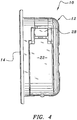
- the heat sealable inflator 10 of the invention comprises a generally rectangular housing 12 having an integral peripheral flange 14.
- the material constituting the housing 12 with its flange 14 is composed of a heat sealable material such as polyurethane that may be heat sealed to conventional inflatable articles such as personal floatation devices, life rafts, and the like (not shown).
- the material constituting the housing 12 and its integral flange 14 is of a generally softer material having a hardness in the range of 40 to 90 on the durometer scale Shore D and a tensile strength of about 400 bar (5800 psi).
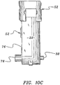
- an exhaust port 18 formed in the rear surface 16 of the inflator housing 12 is an exhaust port 18 which provides fluid communication from the inflator 10 into the inflatable article (not shown).
- the inflator 10 is adapted to receive the threaded neck of a gas cylinder (shown in phantom as numeral 20) such that upon release of the gas therefrom, the gas may flow through the inflator 10 and then out the exhaust port 18 (see Fig. 2 ) into the inflatable article (not shown).
- a gas cylinder shown in phantom as numeral 20
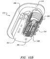
- the inflator 10 comprises a firing lever 22 to which is tethered a jerk handle 24 by means of a braided lanyard 26.
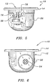
- a removable safety clip 28 is provided for retaining the firing lever 22 into its normal unfired position substantially flush with the left side 30 of the inflator (see Figs. 5 and 6 ) such that the firing lever 22 does not protrude therefrom and otherwise be inadvertently caught or snagged.
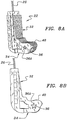
- the firing lever 22 is shown in Figs. 8A, 8B and 8C and generally comprises an L-shaped configuration having an upstanding arm 32 to which the lanyard 26 is inserted into and tightly and permanently secured such as by staking.
- the lower leg portion 34 of the firing lever 22 comprises a pivot hole 36 through which a pivot pin 38 is inserted and a cammed surface 40 which is operatively designed to cam against the actuator pin 42 of the pierce pin assembly 44 described hereinafter in more detail.
- the pivot hole may be a plurality of upstanding protrusions 36A encircling the pivot hole 36.
- Figs. 9A-9E illustrate the housing 12 of the invention with all of the other components removed.
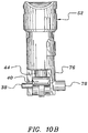
- Figs. 10A-10E illustrate the other components that are assembled within the housing 12 of Fig. 9 .
- These other components shown in Fig. 10 include the firing lever 22 and the safety clip 28 as previously described above and a safety flag 48, preferably colored red, that is snap-fitted between ridges 50 formed in the housing 12.
- the safety flag 48 is hidden behind the firing lever 22 when the firing lever 22 is in its unactuated/unfired condition. Conversely, the flag 48 is exposed when the firing lever 22 is actuated, thereby indicating a fired condition.
- a generally cylindrical sleeve 52 is molded in-situ with the housing 12.
- the cylindrical sleeve 52 comprises at its upper portion 42 a threaded bore 56 for receiving the threaded neck of the gas cylinder 20.
- the pierce pin assembly 44 is reciprocatably positioned within a longitudinal bore 60 of the housing 12.
- the pierce pin assembly 44 comprises an actuator pin 42 with a firing pin 54 staked therein for piercing the frangible seal of the gas cartridge 20 when actuated.
- the actuator pin 42 comprises an O-ring groove 62 at its lower end for receiving a conventional O-ring 64.
- the O-ring 64 prevents air flowing from the gas cartridge 20 from escaping from the longitudinal bore 60 such that it is directed to exit the housing 12 via exhaust port 18 to flow into and inflate the inflatable.
- a check valve is employed.
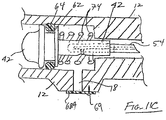
- the preferred embodiment of the check valve best illustrated in Figs. 11A and 11B comprises a seat assembly 66 that is reciprocally and sealingly positioned over the actuator pin 42.
- the seat assembly 66 comprises an annular seal 68 positioned within a retainer clip 70 for support.
- the annular seal 68 functions to seal against the opening 72 in the bore 60 leading into the threaded bore 56 and against the outer cylindrical surface of the actuator pin 42.
- a spring 74 is positioned between the seat assembly 66 and the O-ring groove 62 to urge the seal 68 into sealing engagement with the opening 72 and to allow the seat assembly 66 to blow back by the force of the escaping gas from the cartridge 20 upon firing.
- the spring 74 also functions to return the seat assembly 66 to its sealing engagement with the opening 72 after the gas has escaped, thereby preventing leakage of the inflated inflatable in the event the gas cartridge 20 is removed.
- FIG. 11C Another embodiment of the check valve is illustrated in Fig. 11C and comprises a flapper valve 68A that secured over the exhaust port 18 by a fastener 69.
- the flapper valve is composed of a sealing material that forms a seal with the exhaust port 18 when the inflatable is inflated, thereby allowing the gas cartridge 20 to be removed without deflation of the inflatable.
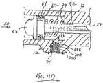
- FIG. 11D Still another embodiment of the check valve is illustrated in Fig. 11D and comprises an annular seal 68B centered within a retainer ring 70A for support.
- the annular seal 68B functions to seal against the exhaust port 18.
- a spring 74B is positioned between the retainer ring 70A and an annular mounting ring 71 secured to the housing 12 to urge annular seal 68B into sealing engagement with the exhaust port 18 and to allow annular seal 68B to blow back by the force of the escaping gas from the cartridge 20 upon firing.
- the spring 74B also functions to return the annular seal 68B to its sealing engagement with the exhaust port 18 after the gas has escaped, thereby preventing leakage of the inflated inflatable in the event the gas cartridge 20 is removed.
- the pierce pin 54 may comprise a central passageway that allows the flow of gas through the pierce pin 54 and the actuator pin 42 to exit therefrom proximate to the exhaust port 18.
- the pierce pin 54 may simply be fluted as shown in the other figures whereupon the escaping gas simply flows through the flute on the pierce pin 54 to blow back the seat assembly 66, then around the actuator pin 42 to exit the exhaust port 18.
- the cylindrical sleeve 52 of Fig. 10 in combination with the housing of Fig. 9 .
- the material constituting the housing 12 should be of a softer material that is heat sealable with conventional articles to be inflated.
- the material constituting the cylindrical sleeve 52 may be of a significantly harder, high-strength, material such as glass-filled nylon and having a tensile strength of about 2068 bar (30,000 psi).
- the cylindrical sleeve 52 is injection molded in a first step and then the housing 12 is injection molded about the sleeve 52 in a second injection molding step. These two steps may occur with the cylindrical sleeve 52 being insert-molded or with the cylindrical sleeve 52 being formed in-situ in a two-step molding process as more particularly set forth in our concurrently-filed patent application.
- the material constituting the cylindrical sleeve 52 is composed of a much stronger material than that of the housing 12, it should be appreciated that it can better withstand the significant pressures that occur immediately upon actuation when gas is rapidly flowing from the gas cartridge 20 through the housing 12 into the inflatable article. Indeed, the use of the cylindrical sleeve 52 in the structure provides the needed strength to withstand the force of the rapidly-flowing gas from, the cartridge. Yet, the gas contacts only the housing 12 and no portion of the sleeve 52. The likelihood of separation between the materials is therefore essentially eliminated since the gas flows directly into the article being inflated without contacting the bond formed between the materials constituting the sleeve 52 and the housing 12.
- Another significant advantage achieved by utilizing the cylindrical sleeve 52 as described above is the ability to incorporate a depending skirt portion 76 therefrom which forms a socket 78 with a blind hole for receiving the pivot pin 38.
- the socket 78 depending from the skirt 76 is embedded within the housing 12 during the two-step injection process. Consequently, during assembly, the pivot pin 38 may be easily inserted therein without having to pre-drill a hole as in the case of my prior patent, U.S. 5,564,478 .
- the elimination of any need for pre- drilling significantly reduces manufacturing and assembly costs.
- a more detailed description of the manufacturing apparatus and method for forming the blind hole is set forth in our concurrently-filed application noted above.
Landscapes
- Engineering & Computer Science (AREA)
- Mechanical Engineering (AREA)
- Ocean & Marine Engineering (AREA)
- Air Bags (AREA)
- Moulds For Moulding Plastics Or The Like (AREA)
Claims (18)
- Gasgenerator zum Heißversiegeln eines aufblasbaren Gegenstands, welcher in Kombination Folgendes aufweist:eine Hülse (52), die aus einem ersten Material ausgebildet ist und einen oberen Abschnitt (42) aufweist, der eine Gewindebohrung (56) zum Aufnehmen des Halses einer Gaspatrone (20) aufweist;ein Gehäuse (12), das aus einem zweiten Material gebildet ist und einen einteilig damit ausgebildeten Umfangsflansch (14) und eine Längsbohrung (60) aufweist, wobei das Gehäuse (12) um die Hülse (52) ausgebildet ist, und wobei die Hülse (52) an Ort und Stelle mit dem Gehäuse (12) gegossen ist;eine Lochstiftanordnung (44), die hin- und herbeweglich innerhalb der Längsbohrung (60) positioniert ist, um die zerbrechliche Dichtung der Gaspatrone (20) zu durchstechen, woraufhin Gas durch die Längsbohrung (60) und dann zu einem Ausgangsanschluss (18) in den aufblasbaren Gegenstand strömt, ohne die Hülse (52) zu kontaktieren;dadurch gekennzeichnet, dassdas erste Material ein glasgefülltes Nylon ist, das eine Zugfestigkeit von ungefähr 2068 bar aufweist, und das zweite Material ein weicheres Material als das erste Material aufweist, wobei das weichere Material mit dem aufblasbaren Gegenstand heiß versiegelbar ist.
- Heißversiegelungsgenerator nach Anspruch 1, wobei die Lochstiftanordnung einen Aktuatorstift mit einem Schlagbolzen zum Durchstoßen der zerbrechlichen Dichtung der Gaspatrone (20) aufweist, wenn er betätigt wird.
- Heißversiegelungsgenerator nach Anspruch 2, welcher des Weiteren eine Sitzanordnung aufweist, die hin- und herbeweglich und dichtend über dem Aktuatorstift angeordnet ist und den Luftstrom von der Gaspatrone (20) zulässt und den Luftstrom in einer entgegengesetzten Richtung hemmt.
- Heißversiegelungsgenerator nach Anspruch 3, wobei die Sitzanordnung eine ringförmige Dichtung aufweist, die zur Abstützung innerhalb einer Klammer positioniert ist, die eine Dichtung gegen eine Öffnung erzeugt, die in den Gaszylinder führt und gegen die äußere zylindrische Oberfläche des Aktuatorstifts.
- Heißversiegelungsgenerator nach Anspruch 4, welcher des Weiteren eine Feder aufweist, um die ringförmige Dichtung in einen abdichtenden Eingriff mit der Öffnung zu drücken und es der Sitzanordnung zu erlauben, durch die Kraft des austretenden Gases von der Gaspatrone (20) nach der Zündung zurückzuschlagen und die Sitzanordnung in ihren abdichtenden Eingriff mit der Öffnung zurückzuführen, nachdem das Gas ausgetreten ist, wodurch eine Leckage des aufblasbaren Gegenstands in dem Fall verhindert wird, in dem die Gaspatrone (20) entfernt wird.
- Heißversiegelungsgenerator nach Anspruch 1, welcher des Weiteren ein Rückschlagventil aufweist, das über dem Auslassanschluss (18) angeordnet ist und das die Luftströmung von der Gaspatrone (20) durch die Auslassöffnung (18) erlaubt und die Luftströmung in einer Gegenrichtung hemmt.
- Heißversiegelungsgenerator nach Anspruch 6, wobei das Rückschlagventil ein Klappenventil aufweist.
- Heißversiegelungsgenerator nach Anspruch 6, wobei das Rückschlagventil eine federbelastete Dichtung aufweist.
- Heißversiegelungsgenerator nach Anspruch 1, wobei das zweite Material aus einem heißversiegelbaren Material zusammengesetzt ist, das mit dem aufblasbaren Gegenstand heißversiegelt werden kann.
- Heißversiegelungsgenerator nach Anspruch 9, wobei das zweite Material, das mit seinem Flansch (14) das Gehäuse (12) bildet, eine Härte in dem Bereich von 40 bis 90 in der Härteskala Shore D aufweist.
- Heißversiegelungsgenerator nach Anspruch 10, wobei das Material, das das Gehäuse (12) bildet, eine Zugfestigkeit von ungefähr 400 bar aufweist.
- Heißversiegelungsgenerator nach Anspruch 1, welches des Weiteren einen Betätigungshebel aufweist, mit dem mittels einer Kordel ein Zuggriff verbunden ist.
- Heißversiegelungsgenerator nach Anspruch 12, wobei der Betätigungshebel eine L-förmige Ausgestaltung aufweist, die einen nach oben stehenden Arm, an dem die Kordel befestigt ist, und einen unteren Beinabschnitt mit einer Gelenkbohrung und einer gekanteten Oberfläche aufweist, die betriebsfähig an dem Betätigungsstift der Lochstiftanordnung anliegt, wenn der Betätigungshebel auf einem Gelenkstift rotiert, der in die Gelenkbohrung eingeführt ist.
- Heißversiegelungsgenerator nach Anspruch 13, welcher des Weiteren eine Vielzahl von nach oben stehenden Vorsprüngen aufweist, welche die Gelenkbohrung einkreisen, um die Reibung zu verringern.
- Heißversiegelungsgenerator nach Anspruch 1, wobei die Hülse (52) in einem ersten Schritt spritzgegossen ist und dann das Gehäuse (12) um die Hülse (52) in einen zweiten Spritzgießschritt spritzgegossen ist.
- Heißversiegelungsgenerator nach Anspruch 15, wobei die Hülse (52) einen abhängigen Randabschnitt aufweist, der eine Buchse mit einer Sachlochbohrung bildet.
- Heißversiegelungsgenerator nach Anspruch 16, wobei die Buchse, die von dem Rand abhängt, innerhalb des Gehäuses (12) während des zwei Schritte aufweisenden Spritzgießprozesses eingebettet ist, und während des Spritzgießens so abgesperrt ist, dass dadurch eine Sachlochbohrung zum Aufnehmen des Gelenkstifts gebildet wird.
- Heißversiegelungsgenerator nach Anspruch 1, welcher des Weiteren eine Anzeige aufweist, die sichtbar ist, wenn der Generator bereits betätigt worden ist.
Applications Claiming Priority (2)
| Application Number | Priority Date | Filing Date | Title |
|---|---|---|---|
| US11/435,106 US7475711B2 (en) | 2006-05-16 | 2006-05-16 | Heat sealable inflator |
| PCT/US2007/010260 WO2007136509A2 (en) | 2006-05-16 | 2007-04-27 | Heat sealable inflator |
Publications (3)
| Publication Number | Publication Date |
|---|---|
| EP2019779A2 EP2019779A2 (de) | 2009-02-04 |
| EP2019779A4 EP2019779A4 (de) | 2009-06-17 |
| EP2019779B1 true EP2019779B1 (de) | 2017-10-18 |
Family
ID=38723757
Family Applications (1)
| Application Number | Title | Priority Date | Filing Date |
|---|---|---|---|
| EP07776361.3A Active EP2019779B1 (de) | 2006-05-16 | 2007-04-27 | Heissversiegelbarer gasgenerator |
Country Status (9)
| Country | Link |
|---|---|
| US (1) | US7475711B2 (de) |
| EP (1) | EP2019779B1 (de) |
| AU (1) | AU2007254443B2 (de) |
| CA (1) | CA2651727C (de) |
| DK (1) | DK2019779T3 (de) |
| ES (1) | ES2655255T3 (de) |
| MX (1) | MX2008014523A (de) |
| NZ (1) | NZ572583A (de) |
| WO (1) | WO2007136509A2 (de) |
Families Citing this family (13)
| Publication number | Priority date | Publication date | Assignee | Title |
|---|---|---|---|---|
| WO2012027244A1 (en) * | 2010-08-22 | 2012-03-01 | Halkey-Roberts Corporation | Apparatus and method for universally mounting an inflator, exhaust valve or relief valve interiorly of an inflatable article |
| US8926222B2 (en) | 2011-07-29 | 2015-01-06 | Pgs Geophysical As | Method and system of depth triggers for marine geophysical survey cable retriever systems |
| US8469634B2 (en) | 2011-07-29 | 2013-06-25 | Pgs Geophysical As | Method and system of depth triggers for marine geophysical survey cable retriever systems |
| US8882391B2 (en) | 2011-07-29 | 2014-11-11 | Pgs Geophysical As | Method and system of retriever systems for marine geophysical survey cables |
| US8753038B2 (en) | 2011-07-29 | 2014-06-17 | Pgs Geophysical As | Method and system of a marine geophysical survey cable retriever |
| US8998535B2 (en) | 2012-05-18 | 2015-04-07 | Pgs Geophysical As | Method and system of retriever systems for marine geophysical survey sensor streamers |
| US9188687B2 (en) | 2013-11-13 | 2015-11-17 | Pgs Geophysical As | Pressure activated linear locking mechanisms and related methods |
| US9365270B2 (en) * | 2014-02-11 | 2016-06-14 | William Lee | Inflator |
| KR101577067B1 (ko) * | 2014-09-01 | 2015-12-16 | 주식회사 시큐어메딕 | 보호장구 장착용 인플레이터 |
| EP3274253B1 (de) | 2015-03-23 | 2019-09-11 | Halkey-Roberts Corporation | Indikator für manuelle aufblasvorrichtung |
| US20170057604A1 (en) * | 2015-09-02 | 2017-03-02 | Mustang Survival Ulc | Stabilizing Cap for Personal Flotation Device |
| US10485363B2 (en) * | 2017-05-21 | 2019-11-26 | Go Smart, Inc. | Inflatable pillow with adjustable height |
| US11180230B2 (en) * | 2018-06-13 | 2021-11-23 | Halkey-Roberts Corporation | Disposable Inflator |
Family Cites Families (31)
| Publication number | Priority date | Publication date | Assignee | Title |
|---|---|---|---|---|
| US3059814A (en) * | 1959-11-09 | 1962-10-23 | Eugene E Poncel | Actuator for emergency water equipment |
| US3091782A (en) * | 1962-06-11 | 1963-06-04 | Aerotec Ind Inc | Apparatus for flotation of articles on water |
| US3426942A (en) * | 1967-07-31 | 1969-02-11 | Jay El Products Inc | Water-responsive energizing apparatus |
| US3579964A (en) * | 1969-07-01 | 1971-05-25 | Us Navy | Squib-powered automatic inflation device |
| GB1360212A (en) * | 1970-12-21 | 1974-07-17 | Martin J | Survival or like packs particularly suitable for airmen |
| US3702014A (en) * | 1971-02-19 | 1972-11-07 | Us Navy | Squib ejected marker buoy |
| US3754731A (en) * | 1972-01-18 | 1973-08-28 | Halkey Roberts Corp | Inflation manifold valve and flange assembly |
| US3809288A (en) * | 1973-03-26 | 1974-05-07 | G Mackal | Inflation manifold |
| GB1462559A (en) * | 1974-04-17 | 1977-01-26 | Niemann W | Inflation device for buoyant life-saving apparatus |
| US3910457A (en) * | 1974-05-06 | 1975-10-07 | Koch & Sons Inc H | Electronic water-activated parachute release and life vest inflator |
| US4216182A (en) * | 1977-02-01 | 1980-08-05 | Judd Edward A | Inflation manifold, method of and apparatus for heading plastic safety pins therein |
| US4223805A (en) * | 1978-08-04 | 1980-09-23 | Mackal Glenn H | Automatic inflator |
| US4260075A (en) * | 1978-08-01 | 1981-04-07 | Mackal Glenn H | Automatic inflator |
| US4267944A (en) * | 1978-08-07 | 1981-05-19 | Mackal Glenn H | Automatic inflator |
| US4382231A (en) * | 1980-11-17 | 1983-05-03 | Conax Corporation | Fluid conductivity sensor |
| US4513248A (en) * | 1980-11-17 | 1985-04-23 | Conax Corporation | Fluid conductivity sensor |
| US4436159A (en) * | 1981-05-01 | 1984-03-13 | Kidde, Inc. | Manual/electric activated squib actuated discharge valve for fire extinguishers |
| US4627823A (en) * | 1984-07-23 | 1986-12-09 | Glenn Mackal | Safety latched automatic actuator and throwable personal flotation assembly |
| US4894036A (en) * | 1988-08-08 | 1990-01-16 | Switlik Parachute Company, Inc. | Inflator assembly for life vests |
| US5058632A (en) * | 1989-07-20 | 1991-10-22 | Precision Metalcraft Corporation | Filling valve apparatus |
| US5076468A (en) * | 1990-02-28 | 1991-12-31 | Halkey-Roberts Corporation | Squib inflator adaptor |
| US5058933A (en) * | 1990-05-14 | 1991-10-22 | Mackal Glenn H | Rotation and retraction-resistant manifold having integral flange |
| US5058932A (en) | 1990-05-14 | 1991-10-22 | Mackal Glenn H | Annular clip for inflation manifold |
| US5080402A (en) * | 1990-05-14 | 1992-01-14 | Mackal Glenn H | Apparatus for joining an inflation manifold to an inflatable article |
| US5271525A (en) * | 1992-02-18 | 1993-12-21 | Petrie Ross J | Inflation manifold |
| US5564478A (en) * | 1994-09-02 | 1996-10-15 | Halkey-Roberts Corporation | Heat sealable inflator |
| US5597091A (en) * | 1995-02-27 | 1997-01-28 | M.E.T.A. Reasearch Inc. | Safety indicator for an inflation system |
| DE69616979T2 (de) * | 1996-04-25 | 2002-06-06 | Halkey-Roberts Corp., St. Petersburg | Heisssiegelfähiges Aufblasgerät |
| IT1304337B1 (it) * | 1997-10-10 | 2001-03-15 | Giovanni Ceredi | Dispositivo con valvola,ad azionamento automatico e/o manuale, per ilgonfiaggio rapido dei giubbetti di salvataggio od altro |
| US6589087B2 (en) * | 2001-09-07 | 2003-07-08 | Halkey-Roberts Corporation | Automatic inflator with status indicator |
| US6705488B2 (en) * | 2001-09-07 | 2004-03-16 | Halkey-Roberts Corporation | Bobbin for automatic inflator |
-
2006
- 2006-05-16 US US11/435,106 patent/US7475711B2/en active Active
-
2007
- 2007-04-27 DK DK07776361.3T patent/DK2019779T3/en active
- 2007-04-27 ES ES07776361.3T patent/ES2655255T3/es active Active
- 2007-04-27 NZ NZ572583A patent/NZ572583A/en unknown
- 2007-04-27 CA CA2651727A patent/CA2651727C/en active Active
- 2007-04-27 WO PCT/US2007/010260 patent/WO2007136509A2/en not_active Ceased
- 2007-04-27 EP EP07776361.3A patent/EP2019779B1/de active Active
- 2007-04-27 AU AU2007254443A patent/AU2007254443B2/en active Active
- 2007-04-27 MX MX2008014523A patent/MX2008014523A/es active IP Right Grant
Non-Patent Citations (1)
| Title |
|---|
| None * |
Also Published As
| Publication number | Publication date |
|---|---|
| AU2007254443A1 (en) | 2007-11-29 |
| EP2019779A4 (de) | 2009-06-17 |
| NZ572583A (en) | 2011-11-25 |
| AU2007254443B2 (en) | 2013-07-18 |
| ES2655255T3 (es) | 2018-02-19 |
| DK2019779T3 (en) | 2018-01-22 |
| MX2008014523A (es) | 2008-11-27 |
| US20070277903A1 (en) | 2007-12-06 |
| WO2007136509A3 (en) | 2008-03-20 |
| CA2651727C (en) | 2014-12-23 |
| WO2007136509A2 (en) | 2007-11-29 |
| US7475711B2 (en) | 2009-01-13 |
| EP2019779A2 (de) | 2009-02-04 |
| CA2651727A1 (en) | 2007-11-29 |
| WO2007136509A8 (en) | 2008-07-24 |
Similar Documents
| Publication | Publication Date | Title |
|---|---|---|
| EP2019779B1 (de) | Heissversiegelbarer gasgenerator | |
| US5076468A (en) | Squib inflator adaptor | |
| AU2009200406B2 (en) | Automatic inflator with status indicator | |
| AU2004273044B2 (en) | Inflation valve with pneumatic assist | |
| US7673647B2 (en) | Inflation valve with pneumatic assist | |
| US5601124A (en) | Autoinflator with apertured housing | |
| US6705488B2 (en) | Bobbin for automatic inflator | |
| WO2010121078A1 (en) | Manual inflator with cylinder connector and status indicator | |
| US5564478A (en) | Heat sealable inflator | |
| AU2002341594A1 (en) | Bobbin for automatic inflator | |
| US4482081A (en) | Water activated inflation mechanism | |
| EP0803433B1 (de) | Heisssiegelfähiges Aufblasgerät | |
| US20120042965A1 (en) | Apparatus and Method for Mounting an Inflator, Exhaust Valve or Relief Valve Interiorly of an Inflatable Article | |
| US20040061318A1 (en) | Inflation device | |
| WO2022112601A1 (en) | Inflation systems | |
| AU2002332819A1 (en) | Automatic inflator with status indicator | |
| KR20140134730A (ko) | 팽창식 부양체를 팽창시키기 위한 팽창 유닛용 릴리스 장치 |
Legal Events
| Date | Code | Title | Description |
|---|---|---|---|
| PUAI | Public reference made under article 153(3) epc to a published international application that has entered the european phase |
Free format text: ORIGINAL CODE: 0009012 |
|
| 17P | Request for examination filed |
Effective date: 20081127 |
|
| AK | Designated contracting states |
Kind code of ref document: A2 Designated state(s): AT BE BG CH CY CZ DE DK EE ES FI FR GB GR HU IE IS IT LI LT LU LV MC MT NL PL PT RO SE SI SK TR |
|
| AX | Request for extension of the european patent |
Extension state: AL BA HR MK RS |
|
| RIC1 | Information provided on ipc code assigned before grant |
Ipc: B65B 1/04 20060101AFI20090107BHEP |
|
| A4 | Supplementary search report drawn up and despatched |
Effective date: 20090520 |
|
| RIC1 | Information provided on ipc code assigned before grant |
Ipc: B63C 9/19 20060101AFI20090514BHEP |
|
| DAX | Request for extension of the european patent (deleted) | ||
| 17Q | First examination report despatched |
Effective date: 20100517 |
|
| RIC1 | Information provided on ipc code assigned before grant |
Ipc: B63C 9/19 20060101AFI20160707BHEP |
|
| REG | Reference to a national code |
Ref country code: DE Ref legal event code: R079 Ref document number: 602007052742 Country of ref document: DE Free format text: PREVIOUS MAIN CLASS: B65B0001040000 Ipc: B63C0009190000 |
|
| GRAP | Despatch of communication of intention to grant a patent |
Free format text: ORIGINAL CODE: EPIDOSNIGR1 |
|
| RIC1 | Information provided on ipc code assigned before grant |
Ipc: B60C 29/00 20060101ALI20170418BHEP Ipc: B63C 9/19 20060101AFI20170418BHEP |
|
| INTG | Intention to grant announced |
Effective date: 20170523 |
|
| GRAS | Grant fee paid |
Free format text: ORIGINAL CODE: EPIDOSNIGR3 |
|
| GRAA | (expected) grant |
Free format text: ORIGINAL CODE: 0009210 |
|
| AK | Designated contracting states |
Kind code of ref document: B1 Designated state(s): AT BE BG CH CY CZ DE DK EE ES FI FR GB GR HU IE IS IT LI LT LU LV MC MT NL PL PT RO SE SI SK TR |
|
| REG | Reference to a national code |
Ref country code: GB Ref legal event code: FG4D |
|
| REG | Reference to a national code |
Ref country code: CH Ref legal event code: EP |
|
| REG | Reference to a national code |
Ref country code: AT Ref legal event code: REF Ref document number: 937686 Country of ref document: AT Kind code of ref document: T Effective date: 20171115 Ref country code: IE Ref legal event code: FG4D |
|
| REG | Reference to a national code |
Ref country code: DE Ref legal event code: R096 Ref document number: 602007052742 Country of ref document: DE |
|
| REG | Reference to a national code |
Ref country code: SE Ref legal event code: TRGR |
|
| REG | Reference to a national code |
Ref country code: DK Ref legal event code: T3 Effective date: 20180117 |
|
| REG | Reference to a national code |
Ref country code: NL Ref legal event code: FP |
|
| REG | Reference to a national code |
Ref country code: CH Ref legal event code: NV Representative=s name: CABINET ROLAND NITHARDT CONSEILS EN PROPRIETE , CH |
|
| REG | Reference to a national code |
Ref country code: EE Ref legal event code: FG4A Ref document number: E014728 Country of ref document: EE Effective date: 20171122 |
|
| REG | Reference to a national code |
Ref country code: ES Ref legal event code: FG2A Ref document number: 2655255 Country of ref document: ES Kind code of ref document: T3 Effective date: 20180219 |
|
| REG | Reference to a national code |
Ref country code: LT Ref legal event code: MG4D |
|
| PG25 | Lapsed in a contracting state [announced via postgrant information from national office to epo] |
Ref country code: LT Free format text: LAPSE BECAUSE OF FAILURE TO SUBMIT A TRANSLATION OF THE DESCRIPTION OR TO PAY THE FEE WITHIN THE PRESCRIBED TIME-LIMIT Effective date: 20171018 |
|
| PG25 | Lapsed in a contracting state [announced via postgrant information from national office to epo] |
Ref country code: LV Free format text: LAPSE BECAUSE OF FAILURE TO SUBMIT A TRANSLATION OF THE DESCRIPTION OR TO PAY THE FEE WITHIN THE PRESCRIBED TIME-LIMIT Effective date: 20171018 Ref country code: IS Free format text: LAPSE BECAUSE OF FAILURE TO SUBMIT A TRANSLATION OF THE DESCRIPTION OR TO PAY THE FEE WITHIN THE PRESCRIBED TIME-LIMIT Effective date: 20180218 Ref country code: BG Free format text: LAPSE BECAUSE OF FAILURE TO SUBMIT A TRANSLATION OF THE DESCRIPTION OR TO PAY THE FEE WITHIN THE PRESCRIBED TIME-LIMIT Effective date: 20180118 |
|
| REG | Reference to a national code |
Ref country code: GR Ref legal event code: EP Ref document number: 20180400107 Country of ref document: GR Effective date: 20180518 |
|
| REG | Reference to a national code |
Ref country code: FR Ref legal event code: PLFP Year of fee payment: 12 |
|
| REG | Reference to a national code |
Ref country code: DE Ref legal event code: R097 Ref document number: 602007052742 Country of ref document: DE |
|
| REG | Reference to a national code |
Ref country code: FR Ref legal event code: PLFP Year of fee payment: 13 |
|
| PG25 | Lapsed in a contracting state [announced via postgrant information from national office to epo] |
Ref country code: CZ Free format text: LAPSE BECAUSE OF FAILURE TO SUBMIT A TRANSLATION OF THE DESCRIPTION OR TO PAY THE FEE WITHIN THE PRESCRIBED TIME-LIMIT Effective date: 20171018 Ref country code: SK Free format text: LAPSE BECAUSE OF FAILURE TO SUBMIT A TRANSLATION OF THE DESCRIPTION OR TO PAY THE FEE WITHIN THE PRESCRIBED TIME-LIMIT Effective date: 20171018 |
|
| PLBE | No opposition filed within time limit |
Free format text: ORIGINAL CODE: 0009261 |
|
| STAA | Information on the status of an ep patent application or granted ep patent |
Free format text: STATUS: NO OPPOSITION FILED WITHIN TIME LIMIT |
|
| PG25 | Lapsed in a contracting state [announced via postgrant information from national office to epo] |
Ref country code: RO Free format text: LAPSE BECAUSE OF FAILURE TO SUBMIT A TRANSLATION OF THE DESCRIPTION OR TO PAY THE FEE WITHIN THE PRESCRIBED TIME-LIMIT Effective date: 20171018 Ref country code: PL Free format text: LAPSE BECAUSE OF FAILURE TO SUBMIT A TRANSLATION OF THE DESCRIPTION OR TO PAY THE FEE WITHIN THE PRESCRIBED TIME-LIMIT Effective date: 20171018 |
|
| 26N | No opposition filed |
Effective date: 20180719 |
|
| REG | Reference to a national code |
Ref country code: CH Ref legal event code: NV Representative=s name: ACTOSPHERE SARL, CH |
|
| PG25 | Lapsed in a contracting state [announced via postgrant information from national office to epo] |
Ref country code: MC Free format text: LAPSE BECAUSE OF FAILURE TO SUBMIT A TRANSLATION OF THE DESCRIPTION OR TO PAY THE FEE WITHIN THE PRESCRIBED TIME-LIMIT Effective date: 20171018 Ref country code: SI Free format text: LAPSE BECAUSE OF FAILURE TO SUBMIT A TRANSLATION OF THE DESCRIPTION OR TO PAY THE FEE WITHIN THE PRESCRIBED TIME-LIMIT Effective date: 20171018 |
|
| PG25 | Lapsed in a contracting state [announced via postgrant information from national office to epo] |
Ref country code: LU Free format text: LAPSE BECAUSE OF NON-PAYMENT OF DUE FEES Effective date: 20180427 |
|
| PG25 | Lapsed in a contracting state [announced via postgrant information from national office to epo] |
Ref country code: MT Free format text: LAPSE BECAUSE OF NON-PAYMENT OF DUE FEES Effective date: 20180427 |
|
| PG25 | Lapsed in a contracting state [announced via postgrant information from national office to epo] |
Ref country code: TR Free format text: LAPSE BECAUSE OF FAILURE TO SUBMIT A TRANSLATION OF THE DESCRIPTION OR TO PAY THE FEE WITHIN THE PRESCRIBED TIME-LIMIT Effective date: 20171018 |
|
| REG | Reference to a national code |
Ref country code: AT Ref legal event code: UEP Ref document number: 937686 Country of ref document: AT Kind code of ref document: T Effective date: 20171018 |
|
| PG25 | Lapsed in a contracting state [announced via postgrant information from national office to epo] |
Ref country code: HU Free format text: LAPSE BECAUSE OF FAILURE TO SUBMIT A TRANSLATION OF THE DESCRIPTION OR TO PAY THE FEE WITHIN THE PRESCRIBED TIME-LIMIT; INVALID AB INITIO Effective date: 20070427 Ref country code: PT Free format text: LAPSE BECAUSE OF FAILURE TO SUBMIT A TRANSLATION OF THE DESCRIPTION OR TO PAY THE FEE WITHIN THE PRESCRIBED TIME-LIMIT Effective date: 20171018 |
|
| PG25 | Lapsed in a contracting state [announced via postgrant information from national office to epo] |
Ref country code: CY Free format text: LAPSE BECAUSE OF FAILURE TO SUBMIT A TRANSLATION OF THE DESCRIPTION OR TO PAY THE FEE WITHIN THE PRESCRIBED TIME-LIMIT Effective date: 20171018 |
|
| PGFP | Annual fee paid to national office [announced via postgrant information from national office to epo] |
Ref country code: NL Payment date: 20250418 Year of fee payment: 19 |
|
| PGFP | Annual fee paid to national office [announced via postgrant information from national office to epo] |
Ref country code: FI Payment date: 20250424 Year of fee payment: 19 |
|
| PGFP | Annual fee paid to national office [announced via postgrant information from national office to epo] |
Ref country code: DE Payment date: 20250422 Year of fee payment: 19 |
|
| PGFP | Annual fee paid to national office [announced via postgrant information from national office to epo] |
Ref country code: ES Payment date: 20250529 Year of fee payment: 19 Ref country code: DK Payment date: 20250429 Year of fee payment: 19 Ref country code: GB Payment date: 20250418 Year of fee payment: 19 |
|
| PGFP | Annual fee paid to national office [announced via postgrant information from national office to epo] |
Ref country code: IT Payment date: 20250424 Year of fee payment: 19 Ref country code: BE Payment date: 20250418 Year of fee payment: 19 |
|
| PGFP | Annual fee paid to national office [announced via postgrant information from national office to epo] |
Ref country code: FR Payment date: 20250424 Year of fee payment: 19 Ref country code: EE Payment date: 20250424 Year of fee payment: 19 |
|
| PGFP | Annual fee paid to national office [announced via postgrant information from national office to epo] |
Ref country code: GR Payment date: 20250423 Year of fee payment: 19 |
|
| PGFP | Annual fee paid to national office [announced via postgrant information from national office to epo] |
Ref country code: CH Payment date: 20250501 Year of fee payment: 19 |
|
| PGFP | Annual fee paid to national office [announced via postgrant information from national office to epo] |
Ref country code: AT Payment date: 20250423 Year of fee payment: 19 |
|
| PGFP | Annual fee paid to national office [announced via postgrant information from national office to epo] |
Ref country code: IE Payment date: 20250422 Year of fee payment: 19 |
|
| PGFP | Annual fee paid to national office [announced via postgrant information from national office to epo] |
Ref country code: SE Payment date: 20250429 Year of fee payment: 19 |