EP2019737B1 - Apparatus for threading cans - Google Patents
Apparatus for threading cans Download PDFInfo
- Publication number
- EP2019737B1 EP2019737B1 EP07754475A EP07754475A EP2019737B1 EP 2019737 B1 EP2019737 B1 EP 2019737B1 EP 07754475 A EP07754475 A EP 07754475A EP 07754475 A EP07754475 A EP 07754475A EP 2019737 B1 EP2019737 B1 EP 2019737B1
- Authority
- EP
- European Patent Office
- Prior art keywords
- threading
- container
- rollers
- head
- rotation
- Prior art date
- Legal status (The legal status is an assumption and is not a legal conclusion. Google has not performed a legal analysis and makes no representation as to the accuracy of the status listed.)
- Active
Links
Images






Classifications
-
- B—PERFORMING OPERATIONS; TRANSPORTING
- B21—MECHANICAL METAL-WORKING WITHOUT ESSENTIALLY REMOVING MATERIAL; PUNCHING METAL
- B21D—WORKING OR PROCESSING OF SHEET METAL OR METAL TUBES, RODS OR PROFILES WITHOUT ESSENTIALLY REMOVING MATERIAL; PUNCHING METAL
- B21D51/00—Making hollow objects
- B21D51/16—Making hollow objects characterised by the use of the objects
- B21D51/38—Making inlet or outlet arrangements of cans, tins, baths, bottles, or other vessels; Making can ends; Making closures
-
- B—PERFORMING OPERATIONS; TRANSPORTING
- B21—MECHANICAL METAL-WORKING WITHOUT ESSENTIALLY REMOVING MATERIAL; PUNCHING METAL
- B21D—WORKING OR PROCESSING OF SHEET METAL OR METAL TUBES, RODS OR PROFILES WITHOUT ESSENTIALLY REMOVING MATERIAL; PUNCHING METAL
- B21D51/00—Making hollow objects
- B21D51/16—Making hollow objects characterised by the use of the objects
- B21D51/26—Making hollow objects characterised by the use of the objects cans or tins; Closing same in a permanent manner
- B21D51/2615—Edge treatment of cans or tins
-
- B—PERFORMING OPERATIONS; TRANSPORTING
- B21—MECHANICAL METAL-WORKING WITHOUT ESSENTIALLY REMOVING MATERIAL; PUNCHING METAL
- B21H—MAKING PARTICULAR METAL OBJECTS BY ROLLING, e.g. SCREWS, WHEELS, RINGS, BARRELS, BALLS
- B21H3/00—Making helical bodies or bodies having parts of helical shape
- B21H3/02—Making helical bodies or bodies having parts of helical shape external screw-threads ; Making dies for thread rolling
- B21H3/04—Making by means of profiled-rolls or die rolls
Definitions
- the present invention relates to a threading turret assembly according to the preamble of claim 1 and to method of preparing a stress induced plastically deformed container. See for example JP-A-2003320432 which discloses such an assembly and method.
- JP-A-2003320432 , JP-A-2004160468 , CA-A-2536841 and GB-A-189707306 each describe apparatus for forming a screw thread on the neck of a container.
- JP-A-2003320432 and CA-A-2536841 describe apparatus for holding the base of the container during the screw thread forming process.
- the sliding ram may be configured to drive the container to be threaded towards the threader head such that one of the two threading rollers is positioned inside an opening in the container.
- the ram may be configured to move the container away from the threading head after the container has been threaded.
- Fig. 1 is illustrates a plurality of cans prior to and after a threading operation.
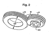
- Fig. 2 is a top perspective view of a pair of meshing threading rollers according to an embodiment.
- Figs. 3(a) to 3(c) illustrate a first threading roller in which Fig. 3(a) illustrates a perspective view of the first threading roller; Fig 3(b) illustrates a front plan view of the first threading roller; and Fig. 3(c) illustrates a section of the first threading roller taken along line A-A of Fig. 3(b) .
- Figs. 4(a) to 4(c) illustrate a second threading roller to mesh with the first threading roller in which Fig. 4(a) illustrates a perspective view of the second threading roller; Fig 4(b) illustrates a front plan view of the second threading roller, and Fig. 4(c) illustrates a section of the second threading roller taken along line B-B of Fig. 4(b) .
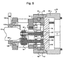
- Fig. 5 is a side view of a threading head according to an embodiment of the invention.
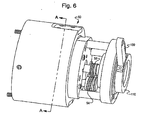
- Fig. 6 is a perspective view of the threading head of Fig. 5 .
- Fig. 7 is a front section view of the threading head taken along line A-A in Fig. 6 .
- Fig. 8 is a rear view of the threading head of Fig. 5 .
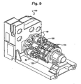
- Fig. 9 is a perspective view of a threading turret with a plurality of threading heads according to an embodiment.
- Fig. 10 is a front plan view of the threading turret of Fig. 9 .
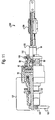
- Fig. 11 is a sectional view of the threading turret taken along line C-C of Fig. 10 .
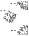
- Figs. 12(a) to 12(c) illustrate sections of the threading turret of Fig. 9 , in which Fig. 12(a) illustrates a front detail view of a plurality of threading heads; Fig. 12(b) is a detail perspective view of a push ram assembly of the threading turret; and Fig. 12(c) is a detail view of a plush plate assembly of the threading turret.
- Fig. 13 is a schematic of a machine line according to an embodiment.
- a device configured to create threads on an open end of a container, such that a threaded cap may be screwed onto the open end of the container to seal an opening in the container.
- the container is a metal (aluminum, tin, etc.) can, and in other embodiments the container is made of a stress-induced plastically deformable material. Other embodiments include methods and systems for utilizing such device(s).
- Figures 1-13 illustrate an apparatus for forming a thread 20 on an article 10.
- An article 10 may be a can, any suitable food or beverage container, jar, bottle or any other suitable article.
- the article 10 has a neck 12 with an open end, an opposite closed end, and a sidewall 14 extending from the closed end. Alternatively, the article 10 may be open at both ends. Threads 20 are formed on the neck 12 of the article 10.
- a cap 5, top, lid or other closure may be added to the article 10 after the threading process.
- Threading describes a process by which raised helical ribs 20 are formed on the neck 12 of a can 10.
- Fig. 1 depicts a group of metal cans 10 in different stages of a threading operation.
- an embryonic metal can 10 center is depicted prior to the impartment of threads 20 onto the can 20.
- Fig. 1 also depicts a threaded metal can 10 (far right) after the impartment of threads 20 onto the can 10 utilizing a device (a threading head) 50 according to an embodiment.
- Figs. 2 and 5 depict an exemplary embodiment of a threading heat 50 according to a threading embodiment, including threading rollers 52 and 54.
- roller 52 has a smaller outer diameter 52D than an outer diameter 54D of roller 54.
- Threading roller 52 is placed inside the open end of the container 10, and roller 54 is placed outside the open end of the container 10.
- the threads 59 of the threading rollers 52, 54 mesh, with, of course, the material of the can 10 interposed in between, as may be seen in Fig. 5 .
- the threading rollers 52, 54 are mounted on a threading head 50 as depicted in Fig. 5 .
- an embryonic (i.e., a can without threads 20) can 10 is transferred into a threading turret 100 (shown in Fig. 9 ) and moved into alignment with the threading head 50.
- the can 10 is moved so that the threading roller 52 is positioned inside the openings of the can 10 and roller 54 is positioned outside the opening of the can 10, as may be seen in Fig. 5 .
- the threading head 50 may be lowered down onto the can 10, and/or both may be moved into position.
- 1 he threading turret 100 may be an independent module or part of a machine line 200, such as shown in Fig. 14.
- the threading head 50 actuates to close the threading rollers 52 and 54 onto the periphery of the open end of the can 10.
- both threading rollers 52 and 54 are moved towards each other to close on the periphery on the open end of the can 10.
- the threading rollers 52 and 54 move in a longitudinal direction (y-plane along the length of the page) toward each other or away from each other.
- the threading rollers 52 and 54 move in two directions, such as in the y-plane and in the z-plane (into the page).
- the can 10 is moved towards the threading roller 52 so that the threading roller 52 is positioned inside the can 10.
- the threading roller 52 inside the can is stationary with respect to the can 10 while the threading roller 54 is moved towards the threading roller 52, and the can 10.
- the threading roller 52 moves towards the threading roller 54 while the threading roller 54 is stationary, and the can 10 is moved towards threading roller 54.
- a threading roller 52, 54 is "stationary” with respect to the can 10.
- a “stationary” threading roller 52 or 54 rotates about its axes during the threading operation, but does not move in the x-, y-, or z- direction with respect to the can 10. The threading operation will be described below.
- the threading rollers 52 and/or 54 When the threading rollers 52 and/or 54 are actuated (or otherwise moved) to close on the periphery of the neck 12 of the can 10, the threads 20 are then formed on the can 10.
- the thread 20 is formed by rotating the threading head 50 with respect to the can 10, which is rotationally stationary with respect to the threading head 50.
- the threading head 50 moves one or both of the threading rollers 52, 54 to contact a sidewall 14 of a neck 12 of a can 10 such that the sidewall 14 is between the respective threads surfaces of the threading rollers 52, 54.
- the threading rollers 52, 54 impart a sufficient pressure to plastically deform the sidewall 14 of the can 10 to impart a thread 20.
- the necessary pressure is determined by the type, material, shape, etc. of the can 10, among other possible things.
- the can 10 is rotated with respect to the threading head 50.
- both the can 10 and the threading head 50 are rotated with respect to each other. Any rotation of either the can 10 and/or the threading head 50 may be utilized to practice the invention providing that the threading rollers 52, 54 may sufficiently impart threads 20 on the can 10.
- rotation of the threading rollers 52, 54 simply results from the rotation of the threading head 50 itself with respect to the can 10, such that friction between the can 10 and the threading rollers 52, 54 results in rotation of the threads 59.
- both the can 10 and the threading rollers 52, 54 are rotated.
- both the threading rollers 52, 54 and the threading head 50 are rotated.
- the threading rollers 52 and 54 have threads 59 about their outer diameters 52D, 54D.
- the threads 59 of the threading rollers 52, 54 mesh with each other as would be understood in the art, to form the threads 20 on the neck 12 of the can 10.
- the threading roller 54 may have a double pitch thread 59, while the threading roller 52 may have a single pitch thread 59.
- threading roller 54 could have quadruple pitch thread 59 while the threading roller 52 could have a double pitch thread 59, etc. Any thread number, pitch, and/or size may be used in some embodiments of the invention as long as the threading rollers 52, 54 will impart sufficient threading 20 onto a can 10.
- the threading rollers 52, 54 are actuated to open and may be extracted from the periphery open end of the now-threaded can 10.
- the threading head 50 and/or the can 10 is then moved away so that the can 10 may be sent down the machine (sometimes referred to as a "production") line 200.
- the cylindrical body 60 of the threading head 50 includes an outer threading roll cam 62 and a inner threading roll cam 64 which are separate components mated to the cylinder 60.
- the threading roll cams 62, 64 may be an integral portion of the cylinder 60, being, for example, machined therein.
- elements 62 and 64 are identical. Any cam surface that may be utilized to practice embodiments of the present invention may be utilized herein.
- a threading head platform 80 on which the threading rollers 52, 54 and the associated components (discussed in greater detail below) are mounted.
- threading roller pinion shaft support components 76 and 78 are located on the platform 80. These support components 76, 78 are respectively linked to rollers 63 and 65, which interface with their respective cams 62 and 64.
- the support assemblies 76, 78 are spring loaded by a spring 74 such that as the cylinder 60 moves relative to the platform 80 in the axial direction, and the rollers 63 and 65 move along the surface of the cams 62, 64.
- the support assemblies 76 and 78, supporting the respective threading geared roll pinion shafts 66, 68 are moved outward. That is, the spring force may be relaxed somewhat due to the rollers 63 and 65 traveling into a portion of the cylinder 60 where there is more room such that the spring 74 may force the support assemblies 76, 78 outward, and thus force the rollers 63, 65 outward.
- the support assembly 76, 78 is moved, the threading roll pinions 67, 68 are moved, and thus the threading rollers 52, 54 are moved.
- only one threading roller 52 or 54 is moved while in another embodiment, both threading rollers 52 and 54 are moved (away from each other and towards each other).
- the outer threading roller 54 is moved outward and the inner threading roller 52 is moved inward when the cylinder 60 is moved upward with respect to the platform 80. That is, when the cylinder 60 is moved upward with respect to the platform 80, for example, in some embodiments, about seven- or eight-tenths of an inch, such that the threading rollers 52, 54 move from an area of the cylinder 60 of lesser cam area diameter to an area of greater cam diameter, the rollers 65 and 63 are pushed outward, thus pushing the threading rollers 52, 54 away from each other, and visa versa.
- threading roller pinion shaft support components 76 and 78 are arranged such that they pivot about the shafts 86, 88 that support pivot gears 82 and 84, thus, during movement of the threading rollers 52, 54. towards and away from each other, the threading rollers 52, 54 follow an arcuate path as opposed to a linear path.
- the structure of the threading head 50 may be such that a linear path may be utilized.
- the movement of the threading rollers 52, 54 is about a tenth of an inch for each roller 52, 54 (that is, the outer roller 54 moves 1/10 of an inch in one direction, and the inner roller 52 moves about 1/10 of an inch in another direction), although the distance of travel could be more or less (especially more), in other embodiments.
- the threader head 50 can also include a link 72 to connect the inner threading roll pinion shaft support component 78 with the inner thread roll cam 64.
- an outer thread roll gear 66 may be included and supported by the outer thread roll pinion shaft 67.
- the following describes an exemplary embodiment of a threading embodiment relating to positioning the can 10 so that the can 10 may be threaded, and the static and dynamic relationship between the can 10, the threading head 50, and the threading turret 100, with respect to a center of rotation of the threading turret 100.
- Cans 10 may be transferred into a threading turret 100 using the vacuum transfer star wheel method, by way of example.
- the threading turrets 100 include multiple threading heads 50 that are each part of a threading station.
- Each threading station may include, in some embodiments, a push plate assembly 120 mounted to a sliding ram 124, and a star wheel 122.
- the sliding ram 124 moves the can 10 into a continuously rotating threading head 50.
- a push plate assembly 120 may include, in some embodiments, a plate with a profiled groove to match the base of the can 10 with a vacuum hole through the plate to allow suction on the base of the can 10. Any other push plate assembly 120 may be utilized.
- FIGs. 9-11 and 12(a)-12(c) there is an exemplary embodiment of a threading turret 100 including threading heads 50 as described above (although other threading turret designs may be utilized in the threading turret 100).
- the push plate assembly 120 operates with a vacuum to hold the can 10 to the push plate.
- the push plate assembly 120 pushes the can 10 into the threading head 50 and the can is aligned by the can holder assembly 110.
- Fig. 11 also illustrates a thread head drive spindle 137 and a spindle drive pinion gear 139 of the threading turret 100.
- the turret 100 includes a can holder assembly 110, that, in some embodiments, is not rotating (as opposed to the threader turret 100), and is mounted on the front of the threading head 50 on bearings 128 to decouple rotation of the threader head 50, and includes a rotation arm 130 to prevent rotation of a can stop, as may be seen in Figs. 5 and 11 .
- the can holder assembly 110 includes an air bladder 140 ( Fig. 5 ) that inflates with air to effectively grip the can 10 (i.e., the air expands the bladder 140 to grip the can 10 to hold the can 10 in place).
- the inflation air is passed through the rotation arm 130, shown in Fig. 5 .
- the bladder 140 is inflated after the can 10 is pushed towards the threading head 50 such that the inner threading roller 52 is inside the opening at the desired depth (with respect to the longitudinal axis of the can 10) for threading.
- the can 10 effectively will not move. That is, the can 10 is held stationary with respect to the particular threading head 50 and station.
- bearing 128 decouples rotation of the threader head 50 from the can holder 110.
- the rotation of the threader head 50 is still not imparted to the can 10.
- a face of the can 10 is always facing the axis of rotation of the threader turret assembly 100. That is, the revolution of the can 10 with respect to the axis of rotation of the threader turret 100 is akin to the revolution of the moon about the Earth - one side is always facing the axis of rotation of the threader turret 100 as the can 10 travels through the threader turret 100.
- Rotation arm 130 is rigidly connected to the turret 100 to prevent the can 10 from rotating in the threading head 50 station.
- the push plate 120 and can holder assembly 110 act together to prevent the can 10 from rotating in the threading head 50 station.
- the push plate 120 can be coated with urethane rubber, or any other suitable substance.
- the spring loaded can holder assembly 110 preloads and prevents the can 10 from turning in the threading head 50 station.
- the can holder assembly 110 applies force on the can 10, but the can 10 does not move (rotate) because the can 10 is pushed against the push plate 120 with sufficient force and friction to prevent any movement of the can 10.
- the threading heads 50 are orbiting about the axis of rotation of the threader turret 100.
- the threading heads 50 are rotating about their axis due to the spindle drive pinion gear 139 connected to the threader heads and a bull gear 132 about the axis of rotation of the threader turret 100, shown in Fig. 11 .
- a rotation is imparted onto the threader heads 50 as a result of gear 139 meshing with the bull gear 132.
- the bull gear 132 is stationary, although in other embodiments, the bull gear 132 could be driven to impart variable control onto the threader heads 50.
- rotation of the bull gear 132 at varying speeds varies the rotation speed of the threading heads 50 accordingly.
- movement of the threading heads 50 are akin to the Earth with respect to its movement about the sun and the rotation of the earth about its axis.
- the threading heads 50 are both rotating and revolving, but rotating in a manner such that the face of the threading head 50 is not constantly facing towards the axis of rotation of the threader turret 100. Because the cans 10 are held stationary within the threading station, and thus revolve in a manner the same as the threader heads 50, but rotate differently than the threader heads 50, there is relative rotation with respect to the cans 10 and the threader heads 50.
- the cans 10 may be held by the can holder 110 such that the can holder 110 moves to always position the face of the cans 10 in the same direction. Because there is relative rotation with respect to the cans 10 and the threader heads 50, there is relative rotation with respect to the cans 10 and the threading rollers 52, 54. That is, in some embodiments of the present invention, because the threader head 50 is rotating with respect to the cans 10 (basically, the cans 10 are not rotating with respect to the threader head 50), the outer threading roller 54 revolves (orbits) about the neck 12 of the can 10, and the inner threading roller 52 rotates inside the neck 12 of the can 10 (from the threader head 50 point of reference). The opening of the can 10 rotates between the inner and outer threading rollers 52, 54.
- the inner threading roller 52 prior to moving the threading rollers 52, 54 to contact the can 10, the inner threading roller 52 is approximately concentric with the opening of the can 10. In other embodiments, the inner threading roller 52 is not concentric. As long as there is clearance between the path of movement of the inner threading roller 52 and the can 10 prior to moving the threading rollers 52, 54 onto the can 10, such non-concentricity is acceptable. Of course, once the threading rollers 52, 54 are moved toward each other, the inner threading roller 52 becomes off-center, and the inner threading roller 52 is no longer concentric with the opening of the can 10.
- the threading rollers 52, 54 do not rotate on their own with respect to the threader head 50. That is, the threading rollers 52, 54 are not powered. However, once the threading rollers 52, 54 are actuated towards the can 10, and thus make contact on the can 10, friction forces between the can 10 and the threading rollers 52, 54 force the threading rollers 52, 54, which are mounted on bearings 127 and 129, as may be seen, for example, in Fig. 5 , to begin to rotate (because, as noted above, the threading rollers 52, 54 are revolving about the can 10).
- the threader head 50 when the threading rollers 52, 54 are rotating, the threader head 50 is configured such that there is a difference in the rotation speed of the threading rollers 52, 54.
- the threader head 50 in Fig. 7 , may include gears 66, 68, 82, 84 that place the threading rollers 52, 54 in gear communication such that the ratio of revolution between the two threading rollers 52, 54 is two to one. That is, the gears 66, 68 maintain a ratio of 2:1 of the inner threading rollers 52 and the outer threading rollers 54.
- gear 66 is twice is large (i.e., a diameter twice as big) as gear 68, thus forming a 2:1 ratio.
- the ratio is determined by gears 66 and 68.
- Gears 82, 84 are change or communication gears.
- the inner threading roller 52 thus rotates two times for every one time that the outer threading roller 54 rotates.
- the ratio may be different. Any ratio that may be utilized to impart acceptable threads 20 onto a can 10 may be utilized to practice some embodiments of the invention.
- threading roller pinion shaft support components 76 and 78 are arranged such that they pivot about shafts 86, 88 supporting pivot gears 82 and 84, thus, during movement of the threading rollers 52, 54 towards and away from each other, the threading rollers 52, 54 follow an arcuate path as opposed to a linear path. It will be seen from, for example, Fig. 7 , that the gears 66, 68, 82, 84 that maintain a rotation ratio between the two threading rollers 52, 54 can tolerate such arcuate paths due to their layout in the threader head 50 with respect to the pivot points.
- the threading rollers 52, 54 make about four orbits about the can 10 before being released, providing enough threads 20 of sufficient quality onto the can 10.
- the number of orbits may be greater or less than four.
- the threading rollers 52, 54 only rotate when they come into contact with the can 10, and then only due to the relative rotation of the threading head 50 with respect to the can 10 (and/or threading station).
- the threading rollers 52, 54 may be powered such that they rotate without the need of relative rotation between the cans 10 and the threading head 50.
- the cans 10 could be rotating and the threading heads 50 could be fixed with respect to the center of rotation of the threading turret 100.
- any rotation scheme that may be utilized to impart threads 20 onto a can 10 may be utilized to practice some embodiments of the present invention.
- the threading head 50 opens (i.e., the threading rollers 52, 54 are retracted away from each other) and the can 10 is retracted from the head 50 by the sliding ram 124 and push plate assembly 120 ( Fig. 9 ).
- the can 10 is then transferred to the next operation by a vacuum transfer star wheel 122.
- Cans 10, according to an embodiment shown in Fig. 13 are fed into a continuously rotating turret 100 either from an infeed track or from a preceding transfer turret 210, which may be part of a machine line 200.
- the star wheels 122 are arranged to hold the cans 10 in position using suction.
- the star wheels 122 may have a vacuum port formed in a channel portion(s) that are fluidly communicating with a source of vacuum (negative pneumatic pressure) via a suitable manifold.
- the vacuum is delivered to the vacuum ports, and the surface area of the cans 10, which are exposed to the suction.
- the vacuum is increased to a degree that the cans 10 are stably held in position as each can 10 passes below the transfer star wheel axis of rotation.
- the turret 100 may contain any number of threader heads 50.
- the turret 100 may include one, two, ten, or any other suitable number of threader heads 50.
- some embodiments of the embodiment include methods of threading a bottle that would result from utilizing the devices describe herein.
- the threading head 50 may be used in conjunction with a recirculation device of a machine arrangement, such as described in U.S. Provisional Application No. 60/787502, filed March 31, 2006 , and related non-provisional application of Jim Marshall, et al. that is titled: METHOD AND APPARATUS FOR BOTTLE RECIRCULATION filed on the same day as the present application.
- the machine arrangement includes a recirculation mechanism (device) and a plurality of turrets that operate on a plurality of cans 10.
- At least one of the turrets comprises an apparatus configured to modify the cans 10 in at least one modifying operation, such as a threading operation on a threading turret 100, as the cans 10 pass from an article infeed to an article discharge of the machine arrangement.
- the recirculation mechanism moves cans 10 from a downstream machine after a first pass and recirculates the cans 10 back to an upstream machine in a recirculation (second) pass so that the cans 10, which are recirculated through the recirculation pass, are again subjected to the at least one modifying operation (or a variant thereof) in a turret that the cans 10 have previously passed through in the first pass.
- the cans 10 are positioned in a first set of alternating pockets in a star wheel (i.e, first, third, fifth, etc.).
- the cans 10 are positioned in a second set of alternating pockets in the star wheel (i.e., second, fourth, sixth, etc.).
- Each turret 100 may include a threading head 50 to correspond to each pocket on a star wheel. Alternatively, a turret 100 may only include a threading head 50 to correspond to alternating pockets.
- the threading heads 50 may have a different diameter, thread depth, or other differences to correspond to the state of the can 10 after having undergone modifying operations in the first pass.
- threading heads 50 that operate on cans 10 in the recirculation pass are modified to further thread a can 10 after the can 10 has undergone other modifying operations.
Landscapes
- Engineering & Computer Science (AREA)
- Mechanical Engineering (AREA)
- Sealing Of Jars (AREA)
- Specific Conveyance Elements (AREA)
- Filling Of Jars Or Cans And Processes For Cleaning And Sealing Jars (AREA)
Description
- The present invention relates to a threading turret assembly according to the preamble of claim 1 and to method of preparing a stress induced plastically deformed container. See for example
JP-A-2003320432 - Conventional machines for forming a thread have required multiple forming heads and forming turrets. Such conventional apparatus can require significant floor and machine line space. Other conventional threading apparatus require separate machines which may not integrate easily with a machine line, thus slowing down the overall processing time of an article.
JP-A-2003320432 JP-A-2004160468 CA-A-2536841 andGB-A-189707306 JP-A-2003320432 CA-A-2536841 describe apparatus for holding the base of the container during the screw thread forming process. - It is an object of the invention to have an apparatus that can form a thread on an article, such as a beverage container or can in a machine line, that minimizes space and processing time requirement
- This object is achieved by a threading turret assembly according to the features of claim 1 and a method of preparing a stress induced plastically deformed container according to the features of claim 19.
- The sliding ram may be configured to drive the container to be threaded towards the threader head such that one of the two threading rollers is positioned inside an opening in the container. The ram may be configured to move the container away from the threading head after the container has been threaded.
- It is to be understood that both the foregoing general description and the following detailed description are exemplary and explanatory only, and are not restrictive of the invention as claimed.
- These and other features, aspects, and advantages of the present invention will become apparent from the following description, appended claims, and the accompanying exemplary embodiments shown in the drawings, which are briefly described below.
-
Fig. 1 is illustrates a plurality of cans prior to and after a threading operation. -
Fig. 2 is a top perspective view of a pair of meshing threading rollers according to an embodiment. -
Figs. 3(a) to 3(c) illustrate a first threading roller in whichFig. 3(a) illustrates a perspective view of the first threading roller;Fig 3(b) illustrates a front plan view of the first threading roller; andFig. 3(c) illustrates a section of the first threading roller taken along line A-A ofFig. 3(b) . -
Figs. 4(a) to 4(c) illustrate a second threading roller to mesh with the first threading roller in whichFig. 4(a) illustrates a perspective view of the second threading roller;Fig 4(b) illustrates a front plan view of the second threading roller, andFig. 4(c) illustrates a section of the second threading roller taken along line B-B ofFig. 4(b) . -
Fig. 5 is a side view of a threading head according to an embodiment of the invention. -
Fig. 6 is a perspective view of the threading head ofFig. 5 . -
Fig. 7 is a front section view of the threading head taken along line A-A inFig. 6 . -
Fig. 8 is a rear view of the threading head ofFig. 5 . -
Fig. 9 is a perspective view of a threading turret with a plurality of threading heads according to an embodiment. -
Fig. 10 is a front plan view of the threading turret ofFig. 9 . -
Fig. 11 is a sectional view of the threading turret taken along line C-C ofFig. 10 . -
Figs. 12(a) to 12(c) illustrate sections of the threading turret ofFig. 9 , in whichFig. 12(a) illustrates a front detail view of a plurality of threading heads;Fig. 12(b) is a detail perspective view of a push ram assembly of the threading turret; andFig. 12(c) is a detail view of a plush plate assembly of the threading turret. -
Fig. 13 is a schematic of a machine line according to an embodiment. - In an embodiment of the present invention, there is a device configured to create threads on an open end of a container, such that a threaded cap may be screwed onto the open end of the container to seal an opening in the container. In some embodiments, the container is a metal (aluminum, tin, etc.) can, and in other embodiments the container is made of a stress-induced plastically deformable material. Other embodiments include methods and systems for utilizing such device(s).
-
Figures 1-13 illustrate an apparatus for forming athread 20 on anarticle 10. Anarticle 10 may be a can, any suitable food or beverage container, jar, bottle or any other suitable article. Thearticle 10 has a neck 12 with an open end, an opposite closed end, and asidewall 14 extending from the closed end. Alternatively, thearticle 10 may be open at both ends.Threads 20 are formed on the neck 12 of thearticle 10. Acap 5, top, lid or other closure may be added to thearticle 10 after the threading process. - For exemplary purposes only, the below description will describe the threading apparatus and method for use on a
can 10. It will be recognized that any other type of article 10 (such as that described above) may be used. - Threading describes a process by which raised
helical ribs 20 are formed on the neck 12 of acan 10.Fig. 1 depicts a group ofmetal cans 10 in different stages of a threading operation. InFig. 1 , an embryonic metal can 10 (center) is depicted prior to the impartment ofthreads 20 onto thecan 20.Fig. 1 also depicts a threaded metal can 10 (far right) after the impartment ofthreads 20 onto the can 10 utilizing a device (a threading head) 50 according to an embodiment. -
Figs. 2 and5 depict an exemplary embodiment of a threadingheat 50 according to a threading embodiment, includingthreading rollers roller 52 has a smallerouter diameter 52D than anouter diameter 54D ofroller 54.Threading roller 52 is placed inside the open end of thecontainer 10, androller 54 is placed outside the open end of thecontainer 10. In some embodiments of the invention, thethreads 59 of thethreading rollers Fig. 5 . - In some threading embodiments, the
threading rollers head 50 as depicted inFig. 5 . - A brief discussion of how some embodiments of the
threading head 50 operates will now be provided. In some embodiments, an embryonic (i.e., a can without threads 20) can 10 is transferred into a threading turret 100 (shown inFig. 9 ) and moved into alignment with thethreading head 50. Thecan 10 is moved so that thethreading roller 52 is positioned inside the openings of thecan 10 androller 54 is positioned outside the opening of thecan 10, as may be seen inFig. 5 . However, in other embodiments, thethreading head 50 may be lowered down onto thecan 10, and/or both may be moved into position. 1 he threadingturret 100 may be an independent module or part of amachine line 200, such as shown in Fig. 14. - In some threading embodiments, the
threading head 50 actuates to close thethreading rollers can 10. In some embodiments of the present invention, boththreading rollers can 10. For example, when viewed fromFig. 5 , thethreading rollers threading rollers can 10 is moved towards thethreading roller 52 so that thethreading roller 52 is positioned inside thecan 10. Thethreading roller 52 inside the can is stationary with respect to thecan 10 while thethreading roller 54 is moved towards thethreading roller 52, and thecan 10. In other embodiments of the present invention, thethreading roller 52 moves towards thethreading roller 54 while the threadingroller 54 is stationary, and thecan 10 is moved towards threadingroller 54. Athreading roller can 10. A "stationary"threading roller can 10. The threading operation will be described below. - When the threading
rollers 52 and/or 54 are actuated (or otherwise moved) to close on the periphery of the neck 12 of thecan 10, thethreads 20 are then formed on thecan 10. Thethread 20 is formed by rotating the threadinghead 50 with respect to thecan 10, which is rotationally stationary with respect to the threadinghead 50. The threadinghead 50 moves one or both of the threadingrollers sidewall 14 of a neck 12 of acan 10 such that thesidewall 14 is between the respective threads surfaces of the threadingrollers rollers sidewall 14 of thecan 10 to impart athread 20. The necessary pressure is determined by the type, material, shape, etc. of thecan 10, among other possible things. - In other embodiments of the invention, the
can 10 is rotated with respect to the threadinghead 50. In yet other embodiments of the present invention, both thecan 10 and the threadinghead 50 are rotated with respect to each other. Any rotation of either thecan 10 and/or the threadinghead 50 may be utilized to practice the invention providing that the threadingrollers threads 20 on thecan 10. In other embodiments of the present invention, rotation of the threadingrollers head 50 itself with respect to thecan 10, such that friction between thecan 10 and the threadingrollers threads 59. In yet other embodiments of the present invention, both thecan 10 and the threadingrollers rollers head 50 are rotated. - As may be seen generally in some of the figures, for example,
Figs 2-4 , the threadingrollers threads 59 about theirouter diameters threads 59 of the threadingrollers threads 20 on the neck 12 of thecan 10. - In one embodiment the threading
roller 54 may have adouble pitch thread 59, while the threadingroller 52 may have asingle pitch thread 59. However, in other embodiments, threadingroller 54 could havequadruple pitch thread 59 while the threadingroller 52 could have adouble pitch thread 59, etc. Any thread number, pitch, and/or size may be used in some embodiments of the invention as long as the threadingrollers can 10. - When the threading operation is completed for a
can 10, the threadingrollers 52, 54 (one or both) are actuated to open and may be extracted from the periphery open end of the now-threadedcan 10. The threadinghead 50 and/or thecan 10 is then moved away so that thecan 10 may be sent down the machine (sometimes referred to as a "production")line 200. - The following describes some embodiments of the operation of the threading
head 50 in general and the inner workings of the threadinghead 50, in particular. - First, actuation of the threading
roller 52 and/or 54 towards and away from each other will be described. Referring toFigs. 5-8 , and any other applicable figures, thecylindrical body 60 of the threadinghead 50 includes an outerthreading roll cam 62 and a innerthreading roll cam 64 which are separate components mated to thecylinder 60. However, in other embodiments of the present invention the threadingroll cams cylinder 60, being, for example, machined therein. In some embodiments of the invention,elements - Referring to
Figs. 5-8 , there is a threadinghead platform 80 on which thethreading rollers platform 80, threading roller pinionshaft support components support components rollers 63 and 65, which interface with theirrespective cams support assemblies cylinder 60 moves relative to theplatform 80 in the axial direction, and therollers 63 and 65 move along the surface of thecams rollers 63, 65 move from thecam sections support assemblies roll pinion shafts rollers 63 and 65 traveling into a portion of thecylinder 60 where there is more room such that the spring 74 may force thesupport assemblies rollers 63, 65 outward. When thesupport assembly rollers - In some embodiments of the invention, only one
threading roller rollers outer threading roller 54 is moved outward and theinner threading roller 52 is moved inward when thecylinder 60 is moved upward with respect to theplatform 80. That is, when thecylinder 60 is moved upward with respect to theplatform 80, for example, in some embodiments, about seven- or eight-tenths of an inch, such that the threadingrollers cylinder 60 of lesser cam area diameter to an area of greater cam diameter, therollers 65 and 63 are pushed outward, thus pushing the threadingrollers cylinder 60 is moved downward, the threadingrollers - In some embodiments of the invention, threading roller pinion
shaft support components shafts rollers rollers head 50 may be such that a linear path may be utilized. The movement of the threadingrollers roller 52, 54 (that is, theouter roller 54 moves 1/10 of an inch in one direction, and theinner roller 52 moves about 1/10 of an inch in another direction), although the distance of travel could be more or less (especially more), in other embodiments. - As can be seen in
Fig. 7 , thethreader head 50 can also include alink 72 to connect the inner threading roll pinionshaft support component 78 with the innerthread roll cam 64. Furthermore, an outerthread roll gear 66 may be included and supported by the outer threadroll pinion shaft 67. - The following describes an exemplary embodiment of a threading embodiment relating to positioning the
can 10 so that thecan 10 may be threaded, and the static and dynamic relationship between thecan 10, the threadinghead 50, and the threadingturret 100, with respect to a center of rotation of the threadingturret 100. -
Cans 10 may be transferred into a threadingturret 100 using the vacuum transfer star wheel method, by way of example. As will be explained in more detail below, the threadingturrets 100 include multiple threading heads 50 that are each part of a threading station. Each threading station may include, in some embodiments, apush plate assembly 120 mounted to a slidingram 124, and astar wheel 122. The slidingram 124 moves thecan 10 into a continuously rotating threadinghead 50. Apush plate assembly 120 may include, in some embodiments, a plate with a profiled groove to match the base of thecan 10 with a vacuum hole through the plate to allow suction on the base of thecan 10. Any otherpush plate assembly 120 may be utilized. - Referring to
Figs. 9-11 and12(a)-12(c) , there is an exemplary embodiment of athreading turret 100 including threading heads 50 as described above (although other threading turret designs may be utilized in the threading turret 100). Thepush plate assembly 120, according to the embodiments described above, operates with a vacuum to hold thecan 10 to the push plate. Thepush plate assembly 120 pushes thecan 10 into the threadinghead 50 and the can is aligned by thecan holder assembly 110.Fig. 11 also illustrates a threadhead drive spindle 137 and a spindledrive pinion gear 139 of the threadingturret 100. - The
turret 100 includes acan holder assembly 110, that, in some embodiments, is not rotating (as opposed to the threader turret 100), and is mounted on the front of the threadinghead 50 onbearings 128 to decouple rotation of thethreader head 50, and includes arotation arm 130 to prevent rotation of a can stop, as may be seen inFigs. 5 and11 . - In an embodiment, the
can holder assembly 110 includes an air bladder 140 (Fig. 5 ) that inflates with air to effectively grip the can 10 (i.e., the air expands thebladder 140 to grip thecan 10 to hold thecan 10 in place). The inflation air is passed through therotation arm 130, shown inFig. 5 . Thebladder 140 is inflated after thecan 10 is pushed towards the threadinghead 50 such that theinner threading roller 52 is inside the opening at the desired depth (with respect to the longitudinal axis of the can 10) for threading. Thus, once thebladder 140 is inflated, thecan 10 effectively will not move. That is, thecan 10 is held stationary with respect to theparticular threading head 50 and station. - As noted above, bearing 128 decouples rotation of the
threader head 50 from thecan holder 110. Thus, after theinflatable bladder 140 is inflated to grip thecan 10, the rotation of thethreader head 50 is still not imparted to thecan 10. Regarding thecan 10, in some threading embodiments, a face of thecan 10 is always facing the axis of rotation of thethreader turret assembly 100. That is, the revolution of thecan 10 with respect to the axis of rotation of thethreader turret 100 is akin to the revolution of the moon about the Earth - one side is always facing the axis of rotation of thethreader turret 100 as thecan 10 travels through thethreader turret 100.Rotation arm 130 is rigidly connected to theturret 100 to prevent thecan 10 from rotating in the threadinghead 50 station. - The
push plate 120 and canholder assembly 110 act together to prevent thecan 10 from rotating in the threadinghead 50 station. Thepush plate 120 can be coated with urethane rubber, or any other suitable substance. The spring loaded canholder assembly 110 preloads and prevents thecan 10 from turning in the threadinghead 50 station. Thecan holder assembly 110 applies force on thecan 10, but thecan 10 does not move (rotate) because thecan 10 is pushed against thepush plate 120 with sufficient force and friction to prevent any movement of thecan 10. - Regarding the dynamics of the threading heads 50, the threading heads 50 are orbiting about the axis of rotation of the
threader turret 100. The threading heads 50 are rotating about their axis due to the spindledrive pinion gear 139 connected to the threader heads and abull gear 132 about the axis of rotation of thethreader turret 100, shown inFig. 11 . As the threader heads 50 orbit about thebull gear 132, a rotation is imparted onto the threader heads 50 as a result ofgear 139 meshing with thebull gear 132. In some embodiments, thebull gear 132 is stationary, although in other embodiments, thebull gear 132 could be driven to impart variable control onto the threader heads 50. In some embodiments, rotation of thebull gear 132 at varying speeds varies the rotation speed of the threading heads 50 accordingly. Further, in some embodiments of the present invention, movement of the threading heads 50 are akin to the Earth with respect to its movement about the sun and the rotation of the earth about its axis. Thus, the threading heads 50 are both rotating and revolving, but rotating in a manner such that the face of the threadinghead 50 is not constantly facing towards the axis of rotation of thethreader turret 100. Because thecans 10 are held stationary within the threading station, and thus revolve in a manner the same as the threader heads 50, but rotate differently than the threader heads 50, there is relative rotation with respect to thecans 10 and the threader heads 50. It is noted in other embodiments of the present invention that thecans 10 may be held by thecan holder 110 such that thecan holder 110 moves to always position the face of thecans 10 in the same direction. Because there is relative rotation with respect to thecans 10 and the threader heads 50, there is relative rotation with respect to thecans 10 and the threadingrollers threader head 50 is rotating with respect to the cans 10 (basically, thecans 10 are not rotating with respect to the threader head 50), theouter threading roller 54 revolves (orbits) about the neck 12 of thecan 10, and theinner threading roller 52 rotates inside the neck 12 of the can 10 (from thethreader head 50 point of reference). The opening of thecan 10 rotates between the inner andouter threading rollers - In some embodiments, prior to moving the threading
rollers can 10, theinner threading roller 52 is approximately concentric with the opening of thecan 10. In other embodiments, theinner threading roller 52 is not concentric. As long as there is clearance between the path of movement of theinner threading roller 52 and thecan 10 prior to moving the threadingrollers can 10, such non-concentricity is acceptable. Of course, once the threadingrollers inner threading roller 52 becomes off-center, and theinner threading roller 52 is no longer concentric with the opening of thecan 10. - As noted above, in some embodiments of the present invention, the threading
rollers threader head 50. That is, the threadingrollers rollers can 10, and thus make contact on thecan 10, friction forces between thecan 10 and the threadingrollers rollers bearings Fig. 5 , to begin to rotate (because, as noted above, the threadingrollers - In some embodiments of the invention, when the threading
rollers threader head 50 is configured such that there is a difference in the rotation speed of the threadingrollers threader head 50, inFig. 7 , may includegears rollers rollers gears inner threading rollers 52 and theouter threading rollers 54. For example,gear 66 is twice is large (i.e., a diameter twice as big) asgear 68, thus forming a 2:1 ratio. The ratio is determined bygears Gears inner threading roller 52 thus rotates two times for every one time that theouter threading roller 54 rotates. Of course, in other embodiments of the invention, the ratio may be different. Any ratio that may be utilized to impartacceptable threads 20 onto acan 10 may be utilized to practice some embodiments of the invention. - As noted above, threading roller pinion
shaft support components 76 and 78 (Fig. 7 ) are arranged such that they pivot aboutshafts rollers rollers Fig. 7 , that thegears rollers threader head 50 with respect to the pivot points. - Regarding the number of orbits about the
can 10, after the threadingrollers can 10, the threadingrollers can 10 before being released, providingenough threads 20 of sufficient quality onto thecan 10. In other embodiments, the number of orbits may be greater or less than four. - It is noted that while in the above described embodiment of the threading assembly, the threading
rollers can 10, and then only due to the relative rotation of the threadinghead 50 with respect to the can 10 (and/or threading station). In other embodiments, the threadingrollers cans 10 and the threadinghead 50. Indeed, in other embodiments of the present invention, thecans 10 could be rotating and the threading heads 50 could be fixed with respect to the center of rotation of the threadingturret 100. Basically, any rotation scheme that may be utilized to impartthreads 20 onto acan 10 may be utilized to practice some embodiments of the present invention. - After the
threads 20 are formed on thecan 10, the threadinghead 50 opens (i.e., the threadingrollers can 10 is retracted from thehead 50 by the slidingram 124 and push plate assembly 120 (Fig. 9 ). Thecan 10 is then transferred to the next operation by a vacuumtransfer star wheel 122. -
Cans 10, according to an embodiment shown inFig. 13 , are fed into a continuously rotatingturret 100 either from an infeed track or from a precedingtransfer turret 210, which may be part of amachine line 200. Thestar wheels 122 are arranged to hold thecans 10 in position using suction. Thestar wheels 122 may have a vacuum port formed in a channel portion(s) that are fluidly communicating with a source of vacuum (negative pneumatic pressure) via a suitable manifold. The vacuum is delivered to the vacuum ports, and the surface area of thecans 10, which are exposed to the suction. The vacuum is increased to a degree that thecans 10 are stably held in position as each can 10 passes below the transfer star wheel axis of rotation. - It will be recognized that the
turret 100 may contain any number of threader heads 50. For example, theturret 100 may include one, two, ten, or any other suitable number of threader heads 50. - It is further noted that some embodiments of the embodiment include methods of threading a bottle that would result from utilizing the devices describe herein.
- In another embodiment of the invention, the threading
head 50 may used in conjunction with a recirculation device of a machine arrangement, such as described inU.S. Provisional Application No. 60/787502, filed March 31, 2006 cans 10. At least one of the turrets comprises an apparatus configured to modify thecans 10 in at least one modifying operation, such as a threading operation on athreading turret 100, as thecans 10 pass from an article infeed to an article discharge of the machine arrangement. The recirculation mechanism movescans 10 from a downstream machine after a first pass and recirculates thecans 10 back to an upstream machine in a recirculation (second) pass so that thecans 10, which are recirculated through the recirculation pass, are again subjected to the at least one modifying operation (or a variant thereof) in a turret that thecans 10 have previously passed through in the first pass. In the first pass, thecans 10 are positioned in a first set of alternating pockets in a star wheel (i.e, first, third, fifth, etc.). In the recirculation pass, thecans 10 are positioned in a second set of alternating pockets in the star wheel (i.e., second, fourth, sixth, etc.). Eachturret 100 may include a threadinghead 50 to correspond to each pocket on a star wheel. Alternatively, aturret 100 may only include a threadinghead 50 to correspond to alternating pockets. In an embodiment, when thecan 10 is recirculated to a different (alternating) set of pockets, the threading heads 50 may have a different diameter, thread depth, or other differences to correspond to the state of thecan 10 after having undergone modifying operations in the first pass. Thus, threading heads 50 that operate oncans 10 in the recirculation pass are modified to further thread acan 10 after thecan 10 has undergone other modifying operations. - Given the disclosure of the present invention, one versed in the art would appreciate that there may be other embodiments and modifications within the scope and spirit of the invention. Accordingly, all modifications attainable by one versed in the art from the present disclosure within the scope and spirit of the present invention are to be included as further embodiments of the present invention. The scope of the present invention is to be defined as set forth in the following claims.
Claims (22)
- A threading turret (100) assembly, comprising:a threading head (50), the threading head including:a first threading roller (52) with a threaded surface (59); anda second threading roller (54) with a threaded surface (59), andcharacterised by:a container holder (110), configured to apply a gripping force to grip a container (10) and configured to remove the gripping force to release the container (10); andan assembly (120) mounted to a sliding ram (124) including a push plate with a profiled groove to match a base of the container (10) and a vacuum hole, wherein the assembly (120) is configured to provide a vacuum that allows suction on the base of the container (10),wherein the container holder (110) is configured to apply a compression force to the container (10) against the push plate to prevent the container (10) from rotating during a threading head operation.
- The threading turret assembly of claim 1, wherein one or both threading rollers (52, 54) are movable with respect to one another, wherein the threading head (50) is configured to move one or both threading rollers (52, 54) to contact a sidewall (14) of the container (10) with sufficient pressure to plastically deform the sidewall (14) of the container (10) so as to impart a thread (20) onto the sidewall (14) of the container (10) when the threading head (50) is rotated relative to the container (10).
- The threading turret assembly of claim 1, wherein the threading head (50) is configured to move the respective threaded surface (59) of one or both threading rollers (52, 54) towards each other, wherein both threading rollers (52, 54) include threads on their respective threaded surfaces (59) such that threads on the first threading roller (52) interface with the threads of the second threading roller (54) upon bringing the threading rollers together.
- The threading turret assembly of claim 1, wherein one of the threading rollers (52, 54) has a double pitched thread, and the other threading roll (52, 54) has a single pitched thread.
- The threading turret assembly of claim 1, wherein the threading head (50) is configured such that one rotation of one of the threading rollers (52, 54) corresponds to two rotations of the other threading roller (52, 54).
- The threading turret assembly of claim 1, wherein the threading head (50) includes a first cam (62) and a second cam (64), the first and second cams (62, 64) being configured to push respective first and second cam rollers (63, 65) so as to, respectively, push the first threading roller (52) towards the second threading roller (54) and to push the second threading roller (54) towards the first threading roller (52).
- The threading turret assembly of claim 1, wherein the threading head (50) includes:a first cam (62); anda second cam (64),wherein the first and second cams (62, 64) are configured to push respective first and second cam rollers (63, 65), wherein when the first and second cam rollers (63, 65) are moved outward along a surface of their respective cams (62, 64), the first and second threading rollers (52, 54) move away from each other.
- The threading turret assembly of claim 7, wherein when the first and second cam rollers (63, 65) are moved inward along a surface of their respective cams (62, 64), the first and second threading rollers (52, 64) move toward each other.
- The threading turret assembly of claim 7, wherein the first and second threading rollers (52, 54) are actuated by moving the cam rollers (63, 65) on the cams (62, 64) parallel to an axis of rotation of at least one of the threading rollers (52, 54).
- The threading turret assembly of claim 1, wherein the container holder (110) is mounted on the threading head (50) with a rigidly held rotation arm (130) so that the container (10) held within the container holder (110) is non-rotatable.
- The threading turret assembly of claim 1,
wherein the sliding ram (124) is configured to drive the container (10) to be threaded towards the threader head (50) such that one of the two threading rollers (52, 54) is positioned inside an opening in the container (10), and wherein the sliding ram (124) is configured to move the container (10) away from the threading head (50) after the container (10) has been threaded. - The threading turret assembly of claim 1, further comprising:a bull gear (132); anda rotation gear (139) mechanically linked to the threading head (50) and in gear communication with the bull gear (132),wherein relative movement of the rotation gear (139) with respect to the bull gear (132) imparts rotation onto the rotation gear (139) and thus the threading head (50).
- The threading turret assembly of claim 12, wherein the bull gear (132) is configured to rotate, and wherein rotation of the bull gear (132) at varying speeds varies the rotation speed of the threading head (50) accordingly.
- The threading turret assembly of claim 1, further comprising:a bull gear (132) in gear communication with a gear (139) connected to the threading head (50), wherein the threading head (50) is configured to orbit about a center of rotation,wherein the threading turret assembly is configured to impart a rotation onto the threading head (50) as the threading head (50) orbits the center of rotation due to the bull gear (132) meshing with the gear (139) on the threading head (50) as the head (50) orbits, andwherein the bull gear (132) at least one of does not rotate and rotates at a speed different from the rotation of the threading head (50) about the center of rotation.
- The threading turret assembly of claim 10, wherein the rotation arm (130) is rigidly connected to the turret (100).
- The threading turret assembly of claim 1, wherein the push plate (120) includes a coating of urethane rubber.
- The threading turret assembly of claim 10, wherein the container holder (110) includes a bladder (140), and wherein inflation of the bladder (140) adjacent to the container (10) provides the gripping force to hold the container (10), and wherein the threading head (50) assembly is configured to remove the gripping force by allowing air to leave the bladder (140).
- A container forming device comprising,
the threading turret assembly of claim 1; and
a recirculation device. - A method of preparing a stress induced plastically deformed container for use as a threaded sealable container (10), comprising:at least one of (i) automatically placing a curved wall (14) of a plastically deformable container (10) in between two threading rollers (52, 54), and (ii) automatically placing the two threading rollers (52, 54) on either side of the curved wall (14);causing the two threading rollers (52, 54) to contact opposite sides of the curved wall (14);automatically orbiting the threading rollers (52, 54) about the container (10) to impart a helical thread (20) onto the curved wall (14),characterised by using a threading turret (100) assembly, comprising a threading head (50), the threading head including: a first threading roller (52) with a threaded surface 59); and a second threading roller (54) with a threaded surface (59), and a container holder (110), configured to apply a gripping force to grip a container (10) andconfigured to remove the gripping force to release the container (10); and an assembly (120) mounted to a sliding ram (124), wherein the assembly (120) includes a push plate and is configured to provide a vacuum that allows a suction on the base of the container (10), to:apply a vacuum that allows suction on the base of the container (10) with the push plate and to grip the container with the container holder (110), wherein the push plate and the container holder (110) act together to prevent rotation of the container (10) during a threading head operation.
- The method of claim 19, further comprising rotating the threading rollers (52, 54) in opposite directions relative to one another and moving the threading rollers (52, 54) along the curved wall (14) to impart the helical threads (20) onto the curved wall (14).
- The method of claim 19, wherein the threading rollers (52, 54) include threads (59), the method further comprising meshing the threads (59) of the threading rollers (52, 54) with each other with the curved wall (14) in between the threading rollers (52, 54).
- The method of claim 19, wherein gripping the container (10) with the container holder (110)is by inflation of a bladder (140).
Priority Applications (3)
| Application Number | Priority Date | Filing Date | Title |
|---|---|---|---|
| EP11191854.6A EP2428291B1 (en) | 2006-03-31 | 2007-03-30 | Apparatus for threading cans |
| DK11178610.9T DK2390022T3 (en) | 2006-03-31 | 2007-03-30 | Apparatus for threading cans |
| EP11178610.9A EP2390022B8 (en) | 2006-03-31 | 2007-03-30 | Apparatus for threading cans |
Applications Claiming Priority (3)
| Application Number | Priority Date | Filing Date | Title |
|---|---|---|---|
| US78750206P | 2006-03-31 | 2006-03-31 | |
| US11/692,564 US7905130B2 (en) | 2006-03-31 | 2007-03-28 | Apparatus for threading cans |
| PCT/US2007/007959 WO2007123716A1 (en) | 2006-03-31 | 2007-03-30 | Apparatus for threading cans |
Related Child Applications (3)
| Application Number | Title | Priority Date | Filing Date |
|---|---|---|---|
| EP11191854.6A Division EP2428291B1 (en) | 2006-03-31 | 2007-03-30 | Apparatus for threading cans |
| EP11191854.6A Division-Into EP2428291B1 (en) | 2006-03-31 | 2007-03-30 | Apparatus for threading cans |
| EP11178610.9A Division-Into EP2390022B8 (en) | 2006-03-31 | 2007-03-30 | Apparatus for threading cans |
Publications (2)
| Publication Number | Publication Date |
|---|---|
| EP2019737A1 EP2019737A1 (en) | 2009-02-04 |
| EP2019737B1 true EP2019737B1 (en) | 2012-10-03 |
Family
ID=38372400
Family Applications (3)
| Application Number | Title | Priority Date | Filing Date |
|---|---|---|---|
| EP07754475A Active EP2019737B1 (en) | 2006-03-31 | 2007-03-30 | Apparatus for threading cans |
| EP11178610.9A Active EP2390022B8 (en) | 2006-03-31 | 2007-03-30 | Apparatus for threading cans |
| EP11191854.6A Active EP2428291B1 (en) | 2006-03-31 | 2007-03-30 | Apparatus for threading cans |
Family Applications After (2)
| Application Number | Title | Priority Date | Filing Date |
|---|---|---|---|
| EP11178610.9A Active EP2390022B8 (en) | 2006-03-31 | 2007-03-30 | Apparatus for threading cans |
| EP11191854.6A Active EP2428291B1 (en) | 2006-03-31 | 2007-03-30 | Apparatus for threading cans |
Country Status (4)
| Country | Link |
|---|---|
| US (2) | US7905130B2 (en) |
| EP (3) | EP2019737B1 (en) |
| DK (1) | DK2390022T3 (en) |
| WO (1) | WO2007123716A1 (en) |
Families Citing this family (39)
| Publication number | Priority date | Publication date | Assignee | Title |
|---|---|---|---|---|
| US8499602B2 (en) * | 2002-05-10 | 2013-08-06 | Agio International Company, Ltd | Decorative hollow tubing for use in furniture manufacture and method for manufacturing |
| US7905130B2 (en) * | 2006-03-31 | 2011-03-15 | Belvac Production Machinery, Inc. | Apparatus for threading cans |
| US7886894B2 (en) * | 2006-03-31 | 2011-02-15 | Belvac Production Machinery, Inc. | Method and apparatus for bottle recirculation |
| US7818987B2 (en) * | 2006-03-31 | 2010-10-26 | Belvac Production Machinery, Inc. | Method and apparatus for trimming a can |
| US7503741B2 (en) * | 2007-01-16 | 2009-03-17 | Omnitech International, Inc. | Formation of a curl in a unitary closable container |
| WO2008089291A2 (en) * | 2007-01-16 | 2008-07-24 | Omnitech International, Inc. | Formation of a curl in a unitary closable container |
| US8601843B2 (en) | 2008-04-24 | 2013-12-10 | Crown Packaging Technology, Inc. | High speed necking configuration |
| US7784319B2 (en) * | 2008-04-24 | 2010-08-31 | Crown, Packaging Technology, Inc | Systems and methods for monitoring and controlling a can necking process |
| US7997111B2 (en) * | 2008-04-24 | 2011-08-16 | Crown, Packaging Technology, Inc. | Apparatus for rotating a container body |
| US8245551B2 (en) | 2008-04-24 | 2012-08-21 | Crown Packaging Technology, Inc. | Adjustable transfer assembly for container manufacturing process |
| US8464567B2 (en) | 2008-04-24 | 2013-06-18 | Crown Packaging Technology, Inc. | Distributed drives for a multi-stage can necking machine |
| US7770425B2 (en) * | 2008-04-24 | 2010-08-10 | Crown, Packaging Technology, Inc. | Container manufacturing process having front-end winder assembly |
| US8297098B2 (en) | 2009-02-26 | 2012-10-30 | Belvac Production Machinery, Inc. | Dual ram assembly for necker machine |
| WO2012054592A1 (en) * | 2010-10-21 | 2012-04-26 | 3M Innovative Properties Company | Method and apparatus for making aerosol cans for metered dose inhaler |
| KR101387348B1 (en) * | 2012-04-18 | 2014-04-21 | 주식회사 파세코 | Sealing lip molding apparatus |
| USD1033216S1 (en) | 2012-08-10 | 2024-07-02 | Daniel A. Zabaleta | Container cap having frustum shaped sidewall segment enabling nesting |
| USD1033215S1 (en) | 2012-08-10 | 2024-07-02 | Daniel A. Zabaleta | Container lid comprising frustum shaped sidewall and seaming chuck receiving radius |
| US10968010B1 (en) | 2012-08-10 | 2021-04-06 | Daniel A Zabaleta | Resealable container lid and accessories including methods of manufacture and use |
| US12365511B1 (en) | 2012-08-10 | 2025-07-22 | Daniel A Zabaleta | Sealing cap having tamper evidence ring for sealing resealable container and method of use |
| WO2014144055A2 (en) | 2013-03-15 | 2014-09-18 | Ball Corporation | Method and apparatus for forming a threaded neck on a metallic bottle |
| HUE059164T2 (en) | 2013-04-09 | 2022-10-28 | Ball Corp | Aluminum impact extruded bottle with threaded neck made from recycled aluminum and enhanced alloys and it's method of manufacturing |
| CN104289643A (en) * | 2013-07-15 | 2015-01-21 | 上海万盛保温容器有限公司 | Production process and equipment of cylinder rolled threads of insulating container |
| ITVR20130174A1 (en) * | 2013-07-23 | 2015-01-24 | Spl Soluzioni S R L | EQUIPMENT FOR PROCESSING CYLINDRICAL METAL CONTAINERS |
| WO2015076823A1 (en) | 2013-11-22 | 2015-05-28 | Silgan Containers Llc | Can-making apparatus with trimmer chute |
| AU2015213747B2 (en) * | 2014-02-07 | 2019-03-07 | Ball Corporation | Metallic container with a threaded closure |
| PL3110576T3 (en) | 2014-02-27 | 2022-08-16 | Belvac Production Machinery, Inc. | Recirculation systems and methods for can and bottle making machinery |
| FR3019148B1 (en) * | 2014-03-26 | 2016-03-25 | Ardagh Mp West France | METAL CONTAINER COMPRISING A CLAMP ADAPTED TO RECEIVE A SCREW CAPSULE TYPE SHUTTING ELEMENT |
| CN107433305B (en) * | 2016-05-26 | 2020-02-07 | 佛山市定中机械有限公司 | Planetary multi-thread metal can forming equipment |
| US20180044155A1 (en) | 2016-08-12 | 2018-02-15 | Ball Corporation | Apparatus and Methods of Capping Metallic Bottles |
| MX2019009745A (en) | 2017-02-16 | 2020-02-07 | Ball Corp | Apparatus and methods of forming and applying roll-on pilfer proof closures on the threaded neck of metal containers. |
| MX2020002563A (en) | 2017-09-15 | 2020-07-13 | Ball Corp | System and method of forming a metallic closure for a threaded container. |
| MX2021005230A (en) | 2018-11-05 | 2021-06-18 | Ball Corp | Metallic container with a threaded closure. |
| US11446730B2 (en) | 2019-06-26 | 2022-09-20 | Ball Corporation | Method and apparatus for sealing a metallic container with a metallic end closure |
| US12384594B2 (en) | 2021-04-05 | 2025-08-12 | Daniel A. Zabaleta | Threaded container components having frustum shaped surfaces enabling nesting |
| JP7584663B2 (en) * | 2021-07-27 | 2024-11-15 | 日鉄ステンレス株式会社 | Fuel filler pipe manufacturing device and fuel filler pipe manufacturing method |
| CN113680934B (en) * | 2021-08-26 | 2023-11-24 | 自贡中粮金属包装有限公司 | Metal can packaging can opening knurling machine and production process thereof |
| EP4680418A1 (en) | 2023-03-17 | 2026-01-21 | Belvac Production Machinery, Inc. | Metal container with a carrier ring and methods of making the same |
| KR20250112071A (en) * | 2024-01-16 | 2025-07-23 | 주식회사 엘지에너지솔루션 | Rotary can beading apparatus |
| US20250345840A1 (en) * | 2024-05-08 | 2025-11-13 | Stolle Machinery Company, Llc | Thread Forming Apparatus And Associated Method |
Family Cites Families (58)
| Publication number | Priority date | Publication date | Assignee | Title |
|---|---|---|---|---|
| US1621301A (en) | 1927-03-15 | Delivery mechanism for box | ||
| GB189707306A (en) | 1897-03-20 | 1898-03-12 | Thomas William Simpson | Improvements in or connected with Apparatus for Forming and Shaping Screw Threads, Indentations, Projections, or other forms on the exterior of Glass Bottle Necks. |
| US2346376A (en) | 1942-08-17 | 1944-04-11 | Gen Motors Corp | Radiator tube end |
| US2686551A (en) | 1951-04-20 | 1954-08-17 | Continental Can Co | Beading and flanging machine |
| US2928454A (en) | 1956-03-08 | 1960-03-15 | Laxo Ed | Rotary beading machine for forming circumferential beads in can bodies |
| US3096709A (en) | 1961-08-04 | 1963-07-09 | Eldred Company | Decorating machine |
| US3531967A (en) | 1968-08-21 | 1970-10-06 | Werge Eng Corp | Rotary machine for forming circumferential impressions in can bodies |
| US3621530A (en) | 1969-06-30 | 1971-11-23 | Anchor Hocking Corp | Means for molding closure cap gaskets |
| US4030432A (en) | 1975-01-24 | 1977-06-21 | Gulf & Western Manufacturing Company (Hastings) | Can trimming apparatus |
| US3983729A (en) | 1975-02-03 | 1976-10-05 | National Can Corporation | Method and apparatus for necking and flanging containers |
| GB1578142A (en) | 1976-04-22 | 1980-11-05 | Metal Box Co Ltd | Expanding the moughs of hollow articles |
| US4207761A (en) | 1978-12-06 | 1980-06-17 | Weyerhaeuser Company | Apparatus for flanging can bodies |
| US4892184A (en) | 1981-05-15 | 1990-01-09 | Van Dam Machine Corporation | Infeed system for container decorating apparatus |
| US4513595A (en) | 1982-02-08 | 1985-04-30 | Cvacho Daniel S | Methods of necking-in and flanging tubular can bodies |
| DE3504555A1 (en) | 1985-02-11 | 1986-10-30 | Jagenberg AG, 4000 Düsseldorf | DEVICE FOR DISTRIBUTING ITEMS, IN PARTICULAR BOTTLES |
| ES2073722T5 (en) * | 1991-04-17 | 2000-11-01 | Nussbaum Und Guhl Ag | PROCEDURE AND DEVICE FOR THE MANUFACTURE OF THREADED ALUMINUM CANS. |
| SE502578C2 (en) | 1992-12-02 | 1995-11-13 | Star Conveyor Ab | Switching device at a transport path |
| US5605217A (en) | 1993-01-29 | 1997-02-25 | Ambec | Vacuum combiner and vacuum conveyor |
| US5611231A (en) | 1995-04-20 | 1997-03-18 | Capital Formation Inc | Modular base can processing equipment |
| WO1997037786A1 (en) | 1996-04-04 | 1997-10-16 | Bowlin Geoffrey R | Modular can necking apparatus |
| US5704240A (en) * | 1996-05-08 | 1998-01-06 | Aluminum Company Of America | Method and apparatus for forming threads in metal containers |
| GB9613102D0 (en) | 1996-06-21 | 1996-08-28 | Metal Box Plc | Can shaping |
| JPH10128474A (en) * | 1996-10-28 | 1998-05-19 | Mitsubishi Materials Corp | Can flanging equipment |
| JP3116854B2 (en) * | 1997-03-27 | 2000-12-11 | 三菱マテリアル株式会社 | Vacuum manifold for spin flow necking device |
| US6199420B1 (en) | 1997-04-28 | 2001-03-13 | Georg Bartosch | Ram for metal can shaper |
| GB9800937D0 (en) | 1998-01-17 | 1998-03-11 | Metal Box Plc | Flange re-forming apparatus |
| US6050396A (en) | 1998-09-22 | 2000-04-18 | Moore; Leslie A. | Adjustable guide rail for transporting products |
| US6233993B1 (en) * | 1999-05-10 | 2001-05-22 | Sango Co., Ltd. | Method and apparatus for forming a processed portion of a workpiece |
| US6176006B1 (en) | 1999-09-21 | 2001-01-23 | Burr Oak Tool And Gauge Company, Inc. | Rod lock and unlock mechanism for a mechanical tube expander |
| FR2802191B1 (en) | 1999-12-13 | 2002-03-01 | Sidel Sa | DEVICE FOR CONVEYING DISCRETE ENTITIES INCLUDING AN IMPROVED TRANSFER ARM AND INSTALLATION FOR BLOWING CONTAINERS PROVIDED WITH SUCH A DEVICE |
| JP2001259749A (en) * | 2000-03-15 | 2001-09-25 | Calsonic Kansei Corp | Forming method of tube |
| US6644083B2 (en) | 2000-06-19 | 2003-11-11 | Macdonald-Miller Incorporated | Spin forming a tubular workpiece to form a radial flange on a tubular flange and a bead or thick rim on the radial flange |
| JP2002066674A (en) * | 2000-08-21 | 2002-03-05 | Takeuchi Press Ind Co Ltd | Manufacturing method for aluminum threaded container |
| US6378695B1 (en) | 2000-09-15 | 2002-04-30 | Rhett L. Rinne | Conveyor apparatus with adjustable guide rails |
| JP2002102968A (en) | 2000-09-25 | 2002-04-09 | Mitsubishi Materials Corp | Can body manufacturing apparatus and can body manufacturing method |
| DE10156085A1 (en) | 2001-11-16 | 2003-05-28 | Sig Cantec Gmbh & Co Kg | Widening and shaping device has mandrel-like shaping counter-tool with tools having identical or complementary shapes |
| JP2003237752A (en) | 2002-02-20 | 2003-08-27 | Mitsubishi Materials Corp | Bottle cans |
| JP3788371B2 (en) | 2002-02-27 | 2006-06-21 | 三菱マテリアル株式会社 | Bottle can with bottle and bottle can |
| JP4149191B2 (en) | 2002-04-30 | 2008-09-10 | ユニバーサル製缶株式会社 | Metal bottle can manufacturing method and manufacturing apparatus |
| JP3889292B2 (en) | 2002-02-28 | 2007-03-07 | ユニバーサル製缶株式会社 | Bottle can manufacturing equipment |
| US6672122B2 (en) | 2002-05-24 | 2004-01-06 | Hayes Lemmerz International, Inc. | Apparatus and method for conditioning the outer flanges of a vehicle wheel |
| JP2004002557A (en) | 2002-05-31 | 2004-01-08 | Toyobo Co Ltd | Polyester composition and molded product |
| JP2004130386A (en) | 2002-08-09 | 2004-04-30 | Mitsubishi Materials Corp | Screw forming method for bottle can body |
| JP2004160468A (en) | 2002-11-11 | 2004-06-10 | Mitsubishi Materials Corp | Bottle can manufacturing method and screw forming apparatus |
| JP4294391B2 (en) | 2002-11-22 | 2009-07-08 | ユニバーサル製缶株式会社 | Bottle cans and bottle cans with caps |
| JP4298402B2 (en) | 2003-06-30 | 2009-07-22 | ユニバーサル製缶株式会社 | Bottle can, bottle with cap and method for producing bottle can |
| ES2427634T3 (en) | 2003-08-28 | 2013-10-31 | Universal Can Corporation | Bottle manufacturing equipment |
| US20050193796A1 (en) | 2004-03-04 | 2005-09-08 | Heiberger Joseph M. | Apparatus for necking a can body |
| JP4647303B2 (en) | 2004-12-21 | 2011-03-09 | ユニバーサル製缶株式会社 | Bottle can body manufacturing method and bottle can body manufacturing apparatus |
| JP4667854B2 (en) | 2004-12-24 | 2011-04-13 | ユニバーサル製缶株式会社 | Bottle can and manufacturing method thereof |
| FR2881123B1 (en) | 2005-01-24 | 2007-04-13 | Sidel Sas | CONVEYOR DEVICE CAPABLE OF HOSTING FAMILIES OF ARTICLES OF DIFFERENT DIMENSIONS, SUCH AS BOTTLES, BOTTLES OR OTHER |
| ITMI20050397A1 (en) | 2005-03-11 | 2006-09-12 | Frattini Costr Mecc | DEVICE FOR EFFECTIVE OPERATIONS OF DEFORMATION LOCALIZED E-OR EXTENDED IN CONTINUOUS METAL CONTAINERS |
| US7530445B2 (en) | 2006-03-31 | 2009-05-12 | Belvac Production Machinery, Inc. | Long stroke slide assemblies |
| US7886894B2 (en) | 2006-03-31 | 2011-02-15 | Belvac Production Machinery, Inc. | Method and apparatus for bottle recirculation |
| US7818987B2 (en) | 2006-03-31 | 2010-10-26 | Belvac Production Machinery, Inc. | Method and apparatus for trimming a can |
| US7905130B2 (en) * | 2006-03-31 | 2011-03-15 | Belvac Production Machinery, Inc. | Apparatus for threading cans |
| US7464573B2 (en) | 2006-03-31 | 2008-12-16 | Belvac Production Machinery, Inc. | Apparatus for curling an article |
| US7963139B2 (en) | 2006-03-31 | 2011-06-21 | Belvac Production Machinery, Inc. | Apparatus for can expansion |
-
2007
- 2007-03-28 US US11/692,564 patent/US7905130B2/en active Active
- 2007-03-30 WO PCT/US2007/007959 patent/WO2007123716A1/en not_active Ceased
- 2007-03-30 EP EP07754475A patent/EP2019737B1/en active Active
- 2007-03-30 DK DK11178610.9T patent/DK2390022T3/en active
- 2007-03-30 EP EP11178610.9A patent/EP2390022B8/en active Active
- 2007-03-30 EP EP11191854.6A patent/EP2428291B1/en active Active
-
2011
- 2011-02-10 US US13/024,830 patent/US8505350B2/en active Active
Also Published As
| Publication number | Publication date |
|---|---|
| EP2428291B1 (en) | 2016-03-30 |
| US20110164948A1 (en) | 2011-07-07 |
| EP2390022A2 (en) | 2011-11-30 |
| US7905130B2 (en) | 2011-03-15 |
| EP2428291A1 (en) | 2012-03-14 |
| EP2390022B8 (en) | 2013-04-24 |
| EP2019737A1 (en) | 2009-02-04 |
| US20070249424A1 (en) | 2007-10-25 |
| DK2390022T3 (en) | 2013-02-18 |
| EP2390022A3 (en) | 2012-02-01 |
| US8505350B2 (en) | 2013-08-13 |
| HK1168323A1 (en) | 2012-12-28 |
| EP2390022B1 (en) | 2012-12-26 |
| WO2007123716A1 (en) | 2007-11-01 |
Similar Documents
| Publication | Publication Date | Title |
|---|---|---|
| EP2390022B1 (en) | Apparatus for threading cans | |
| EP2001618B1 (en) | Apparatus for curling an article | |
| US7886894B2 (en) | Method and apparatus for bottle recirculation | |
| US8297098B2 (en) | Dual ram assembly for necker machine | |
| US20050193796A1 (en) | Apparatus for necking a can body | |
| EP2001616B1 (en) | Apparatus for can expansion | |
| US7530445B2 (en) | Long stroke slide assemblies | |
| HK1168323B (en) | Apparatus for threading cans | |
| US11819933B2 (en) | Method and apparatus for trimming a container | |
| JP5254562B2 (en) | Container processing method and apparatus | |
| HK1169631A (en) | Long stroke slide assemblies |
Legal Events
| Date | Code | Title | Description |
|---|---|---|---|
| PUAI | Public reference made under article 153(3) epc to a published international application that has entered the european phase |
Free format text: ORIGINAL CODE: 0009012 |
|
| 17P | Request for examination filed |
Effective date: 20081017 |
|
| AK | Designated contracting states |
Kind code of ref document: A1 Designated state(s): AT BE BG CH CY CZ DE DK EE ES FI FR GB GR HU IE IS IT LI LT LU LV MC MT NL PL PT RO SE SI SK TR |
|
| AX | Request for extension of the european patent |
Extension state: AL BA HR MK RS |
|
| RBV | Designated contracting states (corrected) |
Designated state(s): DE GB IT |
|
| 17Q | First examination report despatched |
Effective date: 20100129 |
|
| GRAP | Despatch of communication of intention to grant a patent |
Free format text: ORIGINAL CODE: EPIDOSNIGR1 |
|
| DAX | Request for extension of the european patent (deleted) | ||
| GRAS | Grant fee paid |
Free format text: ORIGINAL CODE: EPIDOSNIGR3 |
|
| RAP1 | Party data changed (applicant data changed or rights of an application transferred) |
Owner name: BELVAC PRODUCTION MACHINERY, INC. |
|
| GRAA | (expected) grant |
Free format text: ORIGINAL CODE: 0009210 |
|
| AK | Designated contracting states |
Kind code of ref document: B1 Designated state(s): DE GB IT |
|
| REG | Reference to a national code |
Ref country code: GB Ref legal event code: FG4D |
|
| REG | Reference to a national code |
Ref country code: DE Ref legal event code: R096 Ref document number: 602007025869 Country of ref document: DE Effective date: 20121129 |
|
| PLBE | No opposition filed within time limit |
Free format text: ORIGINAL CODE: 0009261 |
|
| STAA | Information on the status of an ep patent application or granted ep patent |
Free format text: STATUS: NO OPPOSITION FILED WITHIN TIME LIMIT |
|
| 26N | No opposition filed |
Effective date: 20130704 |
|
| REG | Reference to a national code |
Ref country code: DE Ref legal event code: R097 Ref document number: 602007025869 Country of ref document: DE Effective date: 20130704 |
|
| P01 | Opt-out of the competence of the unified patent court (upc) registered |
Effective date: 20230524 |
|
| PGFP | Annual fee paid to national office [announced via postgrant information from national office to epo] |
Ref country code: GB Payment date: 20260324 Year of fee payment: 20 |
|
| PGFP | Annual fee paid to national office [announced via postgrant information from national office to epo] |
Ref country code: DE Payment date: 20260319 Year of fee payment: 20 |
|
| PGFP | Annual fee paid to national office [announced via postgrant information from national office to epo] |
Ref country code: IT Payment date: 20260324 Year of fee payment: 20 |