EP2019580A2 - Zubehörhalterung - Google Patents
Zubehörhalterung Download PDFInfo
- Publication number
- EP2019580A2 EP2019580A2 EP08252357A EP08252357A EP2019580A2 EP 2019580 A2 EP2019580 A2 EP 2019580A2 EP 08252357 A EP08252357 A EP 08252357A EP 08252357 A EP08252357 A EP 08252357A EP 2019580 A2 EP2019580 A2 EP 2019580A2
- Authority
- EP
- European Patent Office
- Prior art keywords
- mounting
- main body
- bracket assembly
- equipment
- rack mountable
- Prior art date
- Legal status (The legal status is an assumption and is not a legal conclusion. Google has not performed a legal analysis and makes no representation as to the accuracy of the status listed.)
- Granted
Links
- 238000000034 method Methods 0.000 claims description 6
- 229910052751 metal Inorganic materials 0.000 description 18
- 239000002184 metal Substances 0.000 description 18
- 230000000873 masking effect Effects 0.000 description 6
- 239000000835 fiber Substances 0.000 description 3
- RYGMFSIKBFXOCR-UHFFFAOYSA-N Copper Chemical compound [Cu] RYGMFSIKBFXOCR-UHFFFAOYSA-N 0.000 description 2
- 229910000831 Steel Inorganic materials 0.000 description 2
- 229910052782 aluminium Inorganic materials 0.000 description 2
- XAGFODPZIPBFFR-UHFFFAOYSA-N aluminium Chemical compound [Al] XAGFODPZIPBFFR-UHFFFAOYSA-N 0.000 description 2
- 238000005452 bending Methods 0.000 description 2
- 239000004020 conductor Substances 0.000 description 2
- 229910052802 copper Inorganic materials 0.000 description 2
- 239000010949 copper Substances 0.000 description 2
- 210000005069 ears Anatomy 0.000 description 2
- 238000012423 maintenance Methods 0.000 description 2
- 239000000463 material Substances 0.000 description 2
- 239000010959 steel Substances 0.000 description 2
- 239000004606 Fillers/Extenders Substances 0.000 description 1
- 238000009434 installation Methods 0.000 description 1
- 239000002994 raw material Substances 0.000 description 1
- 239000007787 solid Substances 0.000 description 1
- 239000011343 solid material Substances 0.000 description 1
Images








Classifications
-
- H—ELECTRICITY
- H05—ELECTRIC TECHNIQUES NOT OTHERWISE PROVIDED FOR
- H05K—PRINTED CIRCUITS; CASINGS OR CONSTRUCTIONAL DETAILS OF ELECTRIC APPARATUS; MANUFACTURE OF ASSEMBLAGES OF ELECTRICAL COMPONENTS
- H05K7/00—Constructional details common to different types of electric apparatus
- H05K7/14—Mounting supporting structure in casing or on frame or rack
- H05K7/1485—Servers; Data center rooms, e.g. 19-inch computer racks
- H05K7/1488—Cabinets therefor, e.g. chassis or racks or mechanical interfaces between blades and support structures
- H05K7/1489—Cabinets therefor, e.g. chassis or racks or mechanical interfaces between blades and support structures characterized by the mounting of blades therein, e.g. brackets, rails, trays
-
- H—ELECTRICITY
- H04—ELECTRIC COMMUNICATION TECHNIQUE
- H04Q—SELECTING
- H04Q1/00—Details of selecting apparatus or arrangements
- H04Q1/02—Constructional details
- H04Q1/09—Frames or mounting racks not otherwise provided for
-
- H—ELECTRICITY
- H04—ELECTRIC COMMUNICATION TECHNIQUE
- H04Q—SELECTING
- H04Q1/00—Details of selecting apparatus or arrangements
- H04Q1/02—Constructional details
- H04Q1/14—Distribution frames
- H04Q1/142—Terminal blocks for distribution frames
Definitions
- This invention relates to apparatus for mounting rack mountable equipment/accessories to electronic equipment support structures and, more particularly, to grounded brackets for vertically mounting the rack mountable equipment/accessories.
- rack mountable equipment/accessories such as patch panels, power distribution units (PDUs), switches, etc.
- RUs usable rack units
- rack mountable equipment/accessories such as patch panels, power distribution units (PDUs), switches, etc.
- RUs usable rack units
- mounting the equipment/accessories in this manner has various drawbacks.
- horizontally-mounted equipment/accessories occupy RUs that could be used for additional electronic equipment.
- patch cords that run between the equipment/accessories and other electronic equipment, such as servers must be routed from the equipment/accessory horizontally to the side of the structure, vertically up the side of the structure, and horizontally over to the other equipment. To complete this routing can take patch cords from 5 to 9 feet in length to make the required connections. This makes equipment maintenance difficult when patch cords must be removed or replaced.
- a bracket assembly for electronic equipment support structures has an elongated main body, a mounting tab extending from a first edge of the main body, and first and second mounting arms extending from a second edge of the main body, opposite the first edge.
- the mounting tab has an aperture formed therethrough.
- the first mounting arm is positioned adjacent a first end of the main body and extends generally perpendicular to the main body and the mounting tabs and the second mounting arm is positioned adjacent a second end of the main body, opposite the first end, and also extends generally perpendicular to the main body and the mounting tabs.
- an electronic equipment support structure assembly has an electronic equipment support structure and a bracket assembly.
- the electronic equipment support structure has a vertically oriented member having a plurality of holes and the bracket assembly is interconnected with the vertically oriented member.
- the bracket assembly has an elongated main body, a mounting tab extending from the main body, and first and second mounting arms extending from the main body.
- the elongated main body is positioned adjacent to and generally parallel to the vertically oriented member and the mounting tab has an aperture that is aligned with at least one of the holes formed in the vertically oriented member.
- the first mounting arm is positioned adjacent a first end of the main body and extends generally perpendicular to the main body and the mounting tabs and away from the vertically oriented member and the second mounting arm is positioned adjacent a second end of the main body, opposite the first end, and extends generally perpendicular to the main body and the mounting tabs and away from the vertically oriented member.
- a method for mounting rack mountable equipment to an electronic equipment support structure has the steps of: mounting a bracket assembly to a vertically oriented member of the electronic equipment support structure; positioning the rack mountable equipment adjacent and generally parallel to the vertically oriented member such that the equipment is in a generally vertical orientation; and connecting the rack mountable equipment to the bracket assembly between opposing mounting arms of the bracket assembly.
- Fig. 1 is a front perspective view of one example of an accessory bracket with a strain relief bar
- Fig. 2 is a front view of the accessory bracket and strain relief bar of Fig. 1 ;
- Fig. 3 is a side view of the accessory bracket and strain relief bar of Fig. 1 ;
- Fig. 4 is a front perspective view of the accessory bracket and strain relief bar of Fig. 1 with a patch panel frame;
- Fig. 5 is a front view of the accessory bracket, strain relief bar, and patch panel frame of Fig. 4 ;
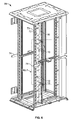
- Fig. 6 is a side perspective view of a cabinet with multiple accessory brackets mounted therein;
- Fig. 7 is an enlarged partial view of Fig. 6 ;
- Fig. 8 is an enlarged partial view of Fig. 7
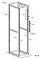
- Fig. 9 is a side perspective view of a 4 post rack with multiple accessory brackets mounted therein;
- Fig. 10 is an enlarged partial view of Fig. 9 ;
- Fig. 11 is a front view of the 4 post rack and accessory brackets of Fig. 9 ;
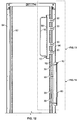
- Fig. 12 is an enlarged partial view of Fig. 11 ;
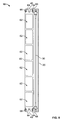
- Fig. 13 is an enlarged partial view of Fig. 12 showing one of the accessory brackets
- Fig. 14 is a partial side perspective view of Fig. 13 ;
- Fig. 15 is an enlarged partial view of Fig. 12 showing the other accessory bracket.
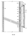
- Fig. 16 is a partial side perspective view of Fig. 15 .
- bracket 10 is configured to be mounted to the vertical frame rail or equipment rail of an electronic equipment support structure, such as a network cabinet, server cabinet, or 4 post rack, and can support various rack mountable equipment/accessories such as a standard 19-inch EIA patch panel frame, a standard 2-inch wide PDU, or a standard rack mounted switch, in a vertical orientation.
- the patch panel frame could include fiber adapter panels (FAPs), pre-terminated copper cartridges, six-port adapter fiber optic cassette modules, or other types of connectivity medium.
- bracket 10 could be extended such that multiple equipment/accessory units could be connected to bracket 10 in various combinations.
- bracket 10 is generally L-shaped, is formed from an electrically conductive material, such as steel or aluminum, and generally has main body 20, mounting tabs 30 and mounting arms 40.
- Main body 20 provides the main support for bracket 10.
- bracket 10 is approximately 4 inches in width, 19 1/8 inches in length, with 11/16 inch wide and 2 3 ⁇ 4 inch long protrusions bent at 90 degrees to the rest of bracket 10 to form mounting arms 40.
- Mounting tabs 30 extend from one edge of main body 20 and provide a means for connecting bracket 10 to the electronic equipment support structure.
- each mounting tab 30 is approximately 1 1/4 inches in width and 2 1/2 inches in length and has an elongated aperture 32 formed therethrough, which is configured to receive a mounting screw or bolt, as described in more detail below.
- the spaces between mounting tabs 30 could be eliminated.
- the spaces between each of the four mounting tabs 30 could be solid material.
- main body 20 should be at least 3 ⁇ 4 inches wide in order to maintain the structural rigidity of bracket 10.
- apertures 32 are elongated along the longitudinal axis of the corresponding mounting tab 30 to provide some flexibility in locating bracket 10 during installation.
- apertures 32 are also generally vertically aligned (as seen in Fig. 3 ) between each other such that apertures 32 will axially align with holes formed in the support structure.
- multiple apertures could be formed in each mounting tab 30 to provide multiple mounting options.
- four mounting tabs 30 are shown extending from the edge of main body 20. However, it will be understood that any number of mounting tabs could be used or one solid mounting tab with multiple apertures could be used. A minimum of two mounting slots or holes are required, but four slots help maintain an electrical ground path (continuity) from the equipment/accessory through bracket 10 to the support structure.
- Mounting arms 40 extend from another edge of main body 20, opposite mounting tabs 30, are generally perpendicular to main body 20, and provide a means for supporting rack mountable electronic equipment/accessories, such as a patch panel frame 60 (see Figs. 4 and 5 ), PDU, switch, etc., in a vertical orientation.
- rack mountable electronic equipment/accessories such as a patch panel frame 60 (see Figs. 4 and 5 ), PDU, switch, etc.
- each mounting arm 40 is approximately 11/16 inches in width and 2 3/4 inches in length and has multiple holes 42 formed therethrough.
- a 2 3 ⁇ 4 inch long mounting arm 40 will provide a 1 1 ⁇ 2 RU space (plus clearance) for one electronic equipment/accessory unit and one strain relief bar.
- a 3 3/4 inch long mounting arm 42 will provide a 2 RU space (plus clearance) that can be used to mount two electronic equipment/accessory units, one unit and up to two strain relief bars, or one unit and one open cable management bar.
- Holes 42 are aligned along the longitudinal axis of the corresponding mounting arm 40 and are spaced apart from each other such that holes 42 will align with holes 66 formed in a standard patch panel frame 60 (see Figs. 4 and 5 ) or other rack mountable equipment/accessory.
- one or more elongated apertures could be formed in each mounting arm 40 to provide more flexibility in mounting various electronic equipment/accessories, such as patch panel frames, PDUs, switches, etc.
- Holes 42 can be tapped to eliminate the nuts and make assembling the equipment/accessories to bracket 10 easier and less complicated. If nuts are used, it may take two hands to hold the components together before tightening.
- mounting arms 40 are configured to support one electronic component/accessory and a strain relief bar 50.
- mounting arms 40 could be extended, and additional holes 42 formed therein, such that multiple electronic components/accessories or combinations thereof could be supported by each bracket 10.
- an extender bracket can also be used to make the mounting arm longer.
- strain relief bar 50 can also be mounted to bracket 10.
- strain relief bar 50 is formed of an electrically conductive material, such as steel or aluminum, is generally U-shaped, and can be used for a variety of purposes, such as preventing cables from bending at an angle that could damage the cables, helping organize the cables, preventing the cables from getting pulled away from the connectors, and keeping the cables away from parts of the cabinet that can potentially move and pinch the cables.
- strain relief bar 50 is approximately 18.98 inches long and 2.81 inches deep, but could be made of varying shapes and sizes depending on the intended use.
- Elongated apertures 52 are formed in each end of strain relief bar 50 and are configured to be axially aligned with corresponding holes 42 in mounting arms 40 and to receive threaded members, which provides a means for mounting strain relief bar 50 to bracket 10.
- strain relief bar 50 To mount strain relief bar 50 to bracket 10, apertures 52 in strain relief bar 50 are aligned with holes 42 in mounting arms 40.
- a threaded member such as a grounding (bond) screw or bolt, is inserted through apertures 52 and into holes 42 in mounting arms 40. If bolts are used, holes 42 will be configured to receive the threaded member therethrough and a nut will be threaded onto the bolt on the opposite side of mounting arm 40 from strain relief bar 50. If screws are used, holes 42 will be threaded and the screws will be threaded directly into the holes 42.
- strain relief bar 50 is grounded to bracket 10.
- Providing a ground path between strain relief bar 50 and bracket 10 can be accomplished in various well-known ways.
- tri-lobular screws could be used that would form threads in holes 42 and provide a ground path between mounting arms 40 and the tri-lobular screws.
- the screws could have serrated edges under the heads of the screws, a star washer could be used between the heads of the screws and strain relief bar 50, or areas in which the heads of the screws will contact strain relief bar 50 could be masked to exposed the bare metal (if strain relief bar 50 is not painted or coated, the heads of the screws will make direct metal to metal contact and masking is not required).
- the nuts and bolts could have serrated edges in the areas that will contact strain relief bar 50 and mounting arms 40, star washers could be used between the nuts and bolts and strain relief bar 50 and mounting arms 40, or areas in which the nuts and the heads of the bolts will contact strain relief bar 50 and mounting arms 40 could be masked to expose the bare metal (if strain relief bar 50 and/or mounting arms 40 are not painted or coated, the nuts and bolts will make direct metal to metal contact and masking is not required).
- a welded, soldered or terminated jumper cable with serrated screw or star washer could also be used.
- exemplary bracket 10 is shown with a standard patch panel frame 60 mounted in a vertical orientation.
- a standard patch panel frame 60 such as a 19-inch EIA patch panel frame, is typically 1.72 to 1.73 inches in width and 19 inches in length.
- a series of openings 62 are formed in frame 60 and are configured to receive various types of components, such as FAPs, pre-terminated copper cartridges, six-port adapter fiber optic cassette modules, etc., as is well-known in the art.
- Mounting ears 64 extend from the ends of frame 60 and each mounting ear 64 has a hole 66 formed therethrough. As can best be seen in Fig. 5 , holes 66 in mounting ears 64 are configured to axially align with holes 42 in mounting arms 40 and to receive bolts or screws therethrough to allow the mounting of frame 60 to bracket 10.
- bracket 10 By using bracket 10 to vertically orient electronic components/accessories on the side of a support structure, RUs that were occupied by electronic components/accessories are now open and can be used for additional electronic equipment. In addition, routing patch cables to the vertically-oriented electronic components/accessories is more efficient and cost effective because shorter cable lengths can be used. For example, by using bracket 10 to mount electronic components/accessories on the side of the support structure, next to other electronic equipment, patch cords as short as 1 1 ⁇ 2 to 2 feet can be used. The use of shorter patch cords also makes equipment maintenance easier when patch cords must be removed or replaced.
- holes 66 in frame 60 are aligned with holes 42 in mounting arms 40.
- a threaded member such as a screw or bolt, is inserted through holes 66 in frame 60 and into holes 42 in mounting arms 40. If bolts are used, holes 42 will be configured to receive the threaded member therethrough and a nut will be threaded onto the bolt on the opposite side of mounting arm 40 from frame 60. If screws are used, holes 42 will be threaded and the screws will be threaded directly into the holes 42.
- frame 60 is grounded to bracket 10.
- Providing a ground path between frame 60 and bracket 10 can be accomplished in various well-known ways.
- tri-lobular screws could be used that would form threads in holes 42 and provide a ground path between mounting arms 40 and the tri-lobular screws.
- the screws could have serrated edges under the heads of the screws, a star washer could be used between the heads of the screws and frame 60, or areas in which the heads of the screws will contact frame 60 could be masked to expose the bare metal (if frame 60 is not painted or coated, the heads of the screws will make direct metal to metal contact and masking is not required).
- the nuts and bolts could have serrated edges in the areas that will contact frame 60 and mounting arms 40, star washers could be used between the nuts and bolts and frame 60 and mounting arms 40, or areas in which the nuts and the heads of the bolts will contact frame 60 and mounting arms 40 could be masked to expose the bare metal (if frame 60 and/or mounting arm 40 are not painted or coated, the nuts and bolts will make direct metal to metal contact and masking is not required).
- cabinet 70 is a network cabinet, such as that shown and described in co-pending U.S. Patent Application Nos. 11/467,956 ; 11/538,884 ; 11/559,708 ; 11/623,358 ; 11/623,839 ; and 11/683,052 , which are incorporated herein by reference.
- bracket 10 can be used with any type of cabinet or other electronic equipment support structure that is adapted to carry electronic equipment, such as servers.
- bracket 10 could also be mounted to equipment rail 73, as discussed below, or any other portion of the cabinet support structure desired.
- bracket 10 is configured to mount patch panel frame 60 at a maximum distance D of 5 5/8 inches from the rear face of vertical frame rail 72, with patch panel frame 72 facing the front of cabinet 70. This offset provides a safe zone to allow clearance between the side panel latches and any mounted equipment or cables attached to the mounted patch panel.
- the first tapped hole in mounting arm 40 is located approximately 0.578 inches from main body 20 in order to center patch panel frame 60 and strain relief bar 50 in between vertical frame rail 72 and side panel structural supports 74.
- bracket 10 is grounded to vertical frame rail 72.
- Providing a ground path between bracket 10 and vertical frame rail 72 can be accomplished in various well-known ways.
- mounting screws 80 could be tri-lobular screws that would form threads in the holes in vertical frame rail 72 and provide a ground path between vertical frame rail 72 and mounting screws 80.
- screws 80 could have serrated edges under the heads of screws 80, a star washer could be used between the heads of screws 80 and bracket 10, or areas in which the heads of screws 80 will contact bracket 10 could be masked to expose the bare metal (if bracket 10 is not painted or coated, the heads of the screws will make direct metal to metal contact and masking is not required).
- a welded, soldered or terminated jumper cable with serrated screw or star washer could also be used.
- bracket 10 is shown mounted to the equipment rail 92 of a 4 post rack 90.
- bracket 10 could also be mounted to vertical frame rail 94, as discussed above, or any other portion of the 4 post rack desired.
- FIG. 12 , 13 , and 15 to mount bracket 10 to equipment rail 92, apertures 32 in mounting tabs 30 are aligned with holes formed in equipment rail 92. Bolts (not shown) are then inserted through holes 32 in mounting tabs 30 and the holes in equipment rail 92 and a nut is threaded onto the bolt on the opposite side of equipment rail 92 from bracket 10.
- bracket 10 is grounded to equipment rail 92.
- Providing a ground path between bracket 10 and equipment rail 92 can be accomplished in various well-known ways.
- the nuts and bolts could have serrated edges in the areas that will contact bracket 10 and equipment rail 92, star washers could be used between the nuts and bolts and bracket 10 and equipment rail 92, or areas in which the nuts and the heads of the bolts will contact bracket 10 and equipment rail 92 could be masked to expose the bare metal (if bracket 10 and/or equipment rail 92 are not painted or coated, the nuts and bolts will make direct metal to metal contact and masking is not required).
Landscapes
- Engineering & Computer Science (AREA)
- Computer Networks & Wireless Communication (AREA)
- Computer Hardware Design (AREA)
- General Engineering & Computer Science (AREA)
- Microelectronics & Electronic Packaging (AREA)
- Casings For Electric Apparatus (AREA)
- Mounting Components In General For Electric Apparatus (AREA)
Applications Claiming Priority (3)
| Application Number | Priority Date | Filing Date | Title |
|---|---|---|---|
| US94941307P | 2007-07-12 | 2007-07-12 | |
| US97029307P | 2007-09-06 | 2007-09-06 | |
| US12/169,249 US9038973B2 (en) | 2007-07-12 | 2008-07-08 | Accessory bracket |
Publications (3)
| Publication Number | Publication Date |
|---|---|
| EP2019580A2 true EP2019580A2 (de) | 2009-01-28 |
| EP2019580A3 EP2019580A3 (de) | 2009-12-23 |
| EP2019580B1 EP2019580B1 (de) | 2012-12-19 |
Family
ID=39772897
Family Applications (1)
| Application Number | Title | Priority Date | Filing Date |
|---|---|---|---|
| EP20080252357 Not-in-force EP2019580B1 (de) | 2007-07-12 | 2008-07-10 | Zubehörhalterung |
Country Status (1)
| Country | Link |
|---|---|
| EP (1) | EP2019580B1 (de) |
Cited By (1)
| Publication number | Priority date | Publication date | Assignee | Title |
|---|---|---|---|---|
| US9681575B2 (en) | 2014-11-04 | 2017-06-13 | International Business Machines Corporation | Enhanced rack design to improve component and cable access |
Citations (1)
| Publication number | Priority date | Publication date | Assignee | Title |
|---|---|---|---|---|
| US20060118321A1 (en) | 2004-12-03 | 2006-06-08 | Hubbell Incorporated. | Cable management system with patch panel |
Family Cites Families (3)
| Publication number | Priority date | Publication date | Assignee | Title |
|---|---|---|---|---|
| US5975962A (en) * | 1998-02-20 | 1999-11-02 | Laukonis; Robert | Network shelf system |
| US6866541B2 (en) * | 2001-07-26 | 2005-03-15 | Panduit Corp. | Angled patch panel with cable support bar for network cable racks |
| US6736670B2 (en) * | 2001-11-16 | 2004-05-18 | Adc Telecommunications, Inc. | Angled RJ to RJ patch panel |
-
2008
- 2008-07-10 EP EP20080252357 patent/EP2019580B1/de not_active Not-in-force
Patent Citations (1)
| Publication number | Priority date | Publication date | Assignee | Title |
|---|---|---|---|---|
| US20060118321A1 (en) | 2004-12-03 | 2006-06-08 | Hubbell Incorporated. | Cable management system with patch panel |
Cited By (2)
| Publication number | Priority date | Publication date | Assignee | Title |
|---|---|---|---|---|
| US9681575B2 (en) | 2014-11-04 | 2017-06-13 | International Business Machines Corporation | Enhanced rack design to improve component and cable access |
| US9686885B2 (en) | 2014-11-04 | 2017-06-20 | International Business Machines Corporation | Enhanced rack design to improve component and cable access |
Also Published As
| Publication number | Publication date |
|---|---|
| EP2019580B1 (de) | 2012-12-19 |
| EP2019580A3 (de) | 2009-12-23 |
Similar Documents
| Publication | Publication Date | Title |
|---|---|---|
| US9038973B2 (en) | Accessory bracket | |
| US6719382B2 (en) | Chassis with modular repositionable optical feedthrough plates | |
| US7488202B2 (en) | Multiport cabling system and method | |
| EP3509407B1 (de) | Halterung für rack-stromverteilereinheit mit drehfunktion | |
| US7760516B2 (en) | Modular UPS systems and methods using modular interconnect assemblies | |
| EP2484189B9 (de) | Werkzeugloses installationssystem und verfahren für u-montierte vorrichtungen | |
| EP3707915B1 (de) | Telekommunikationstafel mit erdungsdraht | |
| US5921402A (en) | Cable management track system | |
| US5396405A (en) | Wiring cabinet having vertically aligned patch panels | |
| US20110141666A1 (en) | Stack of bus bars for a power distribution system | |
| US20090179116A1 (en) | Cable management side bracket | |
| US4679123A (en) | Cable organizing and protection system and method | |
| US7252524B1 (en) | Power interconnect assemblies and methods for configuring the same | |
| CN105308815B (zh) | 基体元件和电涌保护系统 | |
| EP1344438A2 (de) | Baugruppenträger für von der vorderseite und rückseite eingeschobenen einschübe | |
| US11497134B2 (en) | Cable management rack and cable management apparatus for a server cabinet | |
| US5385488A (en) | Patch panel | |
| EP2019580B1 (de) | Zubehörhalterung | |
| US20240155800A1 (en) | Cable management perch for use with rack rail-mounted chassis | |
| US6826058B1 (en) | Telecommunications panel flame shield and wire trough | |
| US8404974B1 (en) | Stuffer cap for patch panel of rack system | |
| CN223612962U (zh) | 一种弱电施工弱电井线路束线机构 | |
| CN220527646U (zh) | 一种通信电缆支撑安装架 | |
| EP3477960B1 (de) | Adaptermulde | |
| US7163180B2 (en) | System and method for routing cables |
Legal Events
| Date | Code | Title | Description |
|---|---|---|---|
| PUAI | Public reference made under article 153(3) epc to a published international application that has entered the european phase |
Free format text: ORIGINAL CODE: 0009012 |
|
| AK | Designated contracting states |
Kind code of ref document: A2 Designated state(s): AT BE BG CH CY CZ DE DK EE ES FI FR GB GR HR HU IE IS IT LI LT LU LV MC MT NL NO PL PT RO SE SI SK TR |
|
| AX | Request for extension of the european patent |
Extension state: AL BA MK RS |
|
| PUAL | Search report despatched |
Free format text: ORIGINAL CODE: 0009013 |
|
| AK | Designated contracting states |
Kind code of ref document: A3 Designated state(s): AT BE BG CH CY CZ DE DK EE ES FI FR GB GR HR HU IE IS IT LI LT LU LV MC MT NL NO PL PT RO SE SI SK TR |
|
| AX | Request for extension of the european patent |
Extension state: AL BA MK RS |
|
| RIC1 | Information provided on ipc code assigned before grant |
Ipc: G02B 6/44 20060101ALI20091118BHEP Ipc: H05K 7/14 20060101ALI20091118BHEP Ipc: H04Q 1/14 20060101AFI20091118BHEP Ipc: H02G 3/04 20060101ALI20091118BHEP |
|
| 17P | Request for examination filed |
Effective date: 20100329 |
|
| AKX | Designation fees paid |
Designated state(s): AT BE BG CH CY CZ DE DK EE ES FI FR GB GR HR HU IE IS IT LI LT LU LV MC MT NL NO PL PT RO SE SI SK TR |
|
| REG | Reference to a national code |
Ref country code: DE Ref legal event code: R079 Ref document number: 602008020931 Country of ref document: DE Free format text: PREVIOUS MAIN CLASS: H05K0007140000 Ipc: H04Q0001140000 |
|
| GRAP | Despatch of communication of intention to grant a patent |
Free format text: ORIGINAL CODE: EPIDOSNIGR1 |
|
| RIC1 | Information provided on ipc code assigned before grant |
Ipc: H04Q 1/02 20060101ALI20120705BHEP Ipc: G02B 6/44 20060101ALI20120705BHEP Ipc: H02G 3/04 20060101ALI20120705BHEP Ipc: H04Q 1/14 20060101AFI20120705BHEP Ipc: H05K 7/14 20060101ALI20120705BHEP |
|
| GRAS | Grant fee paid |
Free format text: ORIGINAL CODE: EPIDOSNIGR3 |
|
| GRAA | (expected) grant |
Free format text: ORIGINAL CODE: 0009210 |
|
| AK | Designated contracting states |
Kind code of ref document: B1 Designated state(s): AT BE BG CH CY CZ DE DK EE ES FI FR GB GR HR HU IE IS IT LI LT LU LV MC MT NL NO PL PT RO SE SI SK TR |
|
| REG | Reference to a national code |
Ref country code: GB Ref legal event code: FG4D |
|
| REG | Reference to a national code |
Ref country code: CH Ref legal event code: EP |
|
| REG | Reference to a national code |
Ref country code: AT Ref legal event code: REF Ref document number: 589918 Country of ref document: AT Kind code of ref document: T Effective date: 20130115 |
|
| REG | Reference to a national code |
Ref country code: DE Ref legal event code: R096 Ref document number: 602008020931 Country of ref document: DE Effective date: 20130214 |
|
| PG25 | Lapsed in a contracting state [announced via postgrant information from national office to epo] |
Ref country code: SE Free format text: LAPSE BECAUSE OF FAILURE TO SUBMIT A TRANSLATION OF THE DESCRIPTION OR TO PAY THE FEE WITHIN THE PRESCRIBED TIME-LIMIT Effective date: 20121219 Ref country code: FI Free format text: LAPSE BECAUSE OF FAILURE TO SUBMIT A TRANSLATION OF THE DESCRIPTION OR TO PAY THE FEE WITHIN THE PRESCRIBED TIME-LIMIT Effective date: 20121219 Ref country code: LT Free format text: LAPSE BECAUSE OF FAILURE TO SUBMIT A TRANSLATION OF THE DESCRIPTION OR TO PAY THE FEE WITHIN THE PRESCRIBED TIME-LIMIT Effective date: 20121219 Ref country code: ES Free format text: LAPSE BECAUSE OF FAILURE TO SUBMIT A TRANSLATION OF THE DESCRIPTION OR TO PAY THE FEE WITHIN THE PRESCRIBED TIME-LIMIT Effective date: 20130330 Ref country code: NO Free format text: LAPSE BECAUSE OF FAILURE TO SUBMIT A TRANSLATION OF THE DESCRIPTION OR TO PAY THE FEE WITHIN THE PRESCRIBED TIME-LIMIT Effective date: 20130319 |
|
| REG | Reference to a national code |
Ref country code: NL Ref legal event code: VDEP Effective date: 20121219 Ref country code: AT Ref legal event code: MK05 Ref document number: 589918 Country of ref document: AT Kind code of ref document: T Effective date: 20121219 |
|
| REG | Reference to a national code |
Ref country code: LT Ref legal event code: MG4D |
|
| PG25 | Lapsed in a contracting state [announced via postgrant information from national office to epo] |
Ref country code: GR Free format text: LAPSE BECAUSE OF FAILURE TO SUBMIT A TRANSLATION OF THE DESCRIPTION OR TO PAY THE FEE WITHIN THE PRESCRIBED TIME-LIMIT Effective date: 20130320 Ref country code: LV Free format text: LAPSE BECAUSE OF FAILURE TO SUBMIT A TRANSLATION OF THE DESCRIPTION OR TO PAY THE FEE WITHIN THE PRESCRIBED TIME-LIMIT Effective date: 20121219 Ref country code: SI Free format text: LAPSE BECAUSE OF FAILURE TO SUBMIT A TRANSLATION OF THE DESCRIPTION OR TO PAY THE FEE WITHIN THE PRESCRIBED TIME-LIMIT Effective date: 20121219 |
|
| PG25 | Lapsed in a contracting state [announced via postgrant information from national office to epo] |
Ref country code: AT Free format text: LAPSE BECAUSE OF FAILURE TO SUBMIT A TRANSLATION OF THE DESCRIPTION OR TO PAY THE FEE WITHIN THE PRESCRIBED TIME-LIMIT Effective date: 20121219 Ref country code: BE Free format text: LAPSE BECAUSE OF FAILURE TO SUBMIT A TRANSLATION OF THE DESCRIPTION OR TO PAY THE FEE WITHIN THE PRESCRIBED TIME-LIMIT Effective date: 20121219 Ref country code: CZ Free format text: LAPSE BECAUSE OF FAILURE TO SUBMIT A TRANSLATION OF THE DESCRIPTION OR TO PAY THE FEE WITHIN THE PRESCRIBED TIME-LIMIT Effective date: 20121219 Ref country code: SK Free format text: LAPSE BECAUSE OF FAILURE TO SUBMIT A TRANSLATION OF THE DESCRIPTION OR TO PAY THE FEE WITHIN THE PRESCRIBED TIME-LIMIT Effective date: 20121219 Ref country code: EE Free format text: LAPSE BECAUSE OF FAILURE TO SUBMIT A TRANSLATION OF THE DESCRIPTION OR TO PAY THE FEE WITHIN THE PRESCRIBED TIME-LIMIT Effective date: 20121219 Ref country code: IS Free format text: LAPSE BECAUSE OF FAILURE TO SUBMIT A TRANSLATION OF THE DESCRIPTION OR TO PAY THE FEE WITHIN THE PRESCRIBED TIME-LIMIT Effective date: 20130419 Ref country code: BG Free format text: LAPSE BECAUSE OF FAILURE TO SUBMIT A TRANSLATION OF THE DESCRIPTION OR TO PAY THE FEE WITHIN THE PRESCRIBED TIME-LIMIT Effective date: 20130319 |
|
| PG25 | Lapsed in a contracting state [announced via postgrant information from national office to epo] |
Ref country code: PL Free format text: LAPSE BECAUSE OF FAILURE TO SUBMIT A TRANSLATION OF THE DESCRIPTION OR TO PAY THE FEE WITHIN THE PRESCRIBED TIME-LIMIT Effective date: 20121219 Ref country code: NL Free format text: LAPSE BECAUSE OF FAILURE TO SUBMIT A TRANSLATION OF THE DESCRIPTION OR TO PAY THE FEE WITHIN THE PRESCRIBED TIME-LIMIT Effective date: 20121219 Ref country code: PT Free format text: LAPSE BECAUSE OF FAILURE TO SUBMIT A TRANSLATION OF THE DESCRIPTION OR TO PAY THE FEE WITHIN THE PRESCRIBED TIME-LIMIT Effective date: 20130419 Ref country code: RO Free format text: LAPSE BECAUSE OF FAILURE TO SUBMIT A TRANSLATION OF THE DESCRIPTION OR TO PAY THE FEE WITHIN THE PRESCRIBED TIME-LIMIT Effective date: 20121219 |
|
| PLBE | No opposition filed within time limit |
Free format text: ORIGINAL CODE: 0009261 |
|
| STAA | Information on the status of an ep patent application or granted ep patent |
Free format text: STATUS: NO OPPOSITION FILED WITHIN TIME LIMIT |
|
| PG25 | Lapsed in a contracting state [announced via postgrant information from national office to epo] |
Ref country code: DK Free format text: LAPSE BECAUSE OF FAILURE TO SUBMIT A TRANSLATION OF THE DESCRIPTION OR TO PAY THE FEE WITHIN THE PRESCRIBED TIME-LIMIT Effective date: 20121219 |
|
| 26N | No opposition filed |
Effective date: 20130920 |
|
| PG25 | Lapsed in a contracting state [announced via postgrant information from national office to epo] |
Ref country code: CY Free format text: LAPSE BECAUSE OF FAILURE TO SUBMIT A TRANSLATION OF THE DESCRIPTION OR TO PAY THE FEE WITHIN THE PRESCRIBED TIME-LIMIT Effective date: 20121219 Ref country code: HR Free format text: LAPSE BECAUSE OF FAILURE TO SUBMIT A TRANSLATION OF THE DESCRIPTION OR TO PAY THE FEE WITHIN THE PRESCRIBED TIME-LIMIT Effective date: 20121219 |
|
| PG25 | Lapsed in a contracting state [announced via postgrant information from national office to epo] |
Ref country code: IT Free format text: LAPSE BECAUSE OF FAILURE TO SUBMIT A TRANSLATION OF THE DESCRIPTION OR TO PAY THE FEE WITHIN THE PRESCRIBED TIME-LIMIT Effective date: 20121219 |
|
| REG | Reference to a national code |
Ref country code: DE Ref legal event code: R097 Ref document number: 602008020931 Country of ref document: DE Effective date: 20130920 |
|
| PG25 | Lapsed in a contracting state [announced via postgrant information from national office to epo] |
Ref country code: MC Free format text: LAPSE BECAUSE OF FAILURE TO SUBMIT A TRANSLATION OF THE DESCRIPTION OR TO PAY THE FEE WITHIN THE PRESCRIBED TIME-LIMIT Effective date: 20121219 |
|
| REG | Reference to a national code |
Ref country code: CH Ref legal event code: PL |
|
| REG | Reference to a national code |
Ref country code: IE Ref legal event code: MM4A |
|
| PG25 | Lapsed in a contracting state [announced via postgrant information from national office to epo] |
Ref country code: CH Free format text: LAPSE BECAUSE OF NON-PAYMENT OF DUE FEES Effective date: 20130731 Ref country code: LI Free format text: LAPSE BECAUSE OF NON-PAYMENT OF DUE FEES Effective date: 20130731 |
|
| PG25 | Lapsed in a contracting state [announced via postgrant information from national office to epo] |
Ref country code: IE Free format text: LAPSE BECAUSE OF NON-PAYMENT OF DUE FEES Effective date: 20130710 |
|
| PGFP | Annual fee paid to national office [announced via postgrant information from national office to epo] |
Ref country code: DE Payment date: 20140729 Year of fee payment: 7 |
|
| PGFP | Annual fee paid to national office [announced via postgrant information from national office to epo] |
Ref country code: FR Payment date: 20140717 Year of fee payment: 7 Ref country code: GB Payment date: 20140729 Year of fee payment: 7 |
|
| PG25 | Lapsed in a contracting state [announced via postgrant information from national office to epo] |
Ref country code: MT Free format text: LAPSE BECAUSE OF FAILURE TO SUBMIT A TRANSLATION OF THE DESCRIPTION OR TO PAY THE FEE WITHIN THE PRESCRIBED TIME-LIMIT Effective date: 20121219 Ref country code: TR Free format text: LAPSE BECAUSE OF FAILURE TO SUBMIT A TRANSLATION OF THE DESCRIPTION OR TO PAY THE FEE WITHIN THE PRESCRIBED TIME-LIMIT Effective date: 20121219 |
|
| PG25 | Lapsed in a contracting state [announced via postgrant information from national office to epo] |
Ref country code: LU Free format text: LAPSE BECAUSE OF NON-PAYMENT OF DUE FEES Effective date: 20130710 Ref country code: HU Free format text: LAPSE BECAUSE OF FAILURE TO SUBMIT A TRANSLATION OF THE DESCRIPTION OR TO PAY THE FEE WITHIN THE PRESCRIBED TIME-LIMIT; INVALID AB INITIO Effective date: 20080710 |
|
| REG | Reference to a national code |
Ref country code: DE Ref legal event code: R119 Ref document number: 602008020931 Country of ref document: DE |
|
| GBPC | Gb: european patent ceased through non-payment of renewal fee |
Effective date: 20150710 |
|
| PG25 | Lapsed in a contracting state [announced via postgrant information from national office to epo] |
Ref country code: GB Free format text: LAPSE BECAUSE OF NON-PAYMENT OF DUE FEES Effective date: 20150710 Ref country code: DE Free format text: LAPSE BECAUSE OF NON-PAYMENT OF DUE FEES Effective date: 20160202 |
|
| REG | Reference to a national code |
Ref country code: FR Ref legal event code: ST Effective date: 20160331 |
|
| PG25 | Lapsed in a contracting state [announced via postgrant information from national office to epo] |
Ref country code: FR Free format text: LAPSE BECAUSE OF NON-PAYMENT OF DUE FEES Effective date: 20150731 |