EP2019524B1 - Electronics module - Google Patents
Electronics module Download PDFInfo
- Publication number
- EP2019524B1 EP2019524B1 EP08159029.1A EP08159029A EP2019524B1 EP 2019524 B1 EP2019524 B1 EP 2019524B1 EP 08159029 A EP08159029 A EP 08159029A EP 2019524 B1 EP2019524 B1 EP 2019524B1
- Authority
- EP
- European Patent Office
- Prior art keywords
- wireless receiver
- modem
- module
- sem
- receiver
- Prior art date
- Legal status (The legal status is an assumption and is not a legal conclusion. Google has not performed a legal analysis and makes no representation as to the accuracy of the status listed.)
- Active
Links
- 238000004891 communication Methods 0.000 claims description 12
- 238000012545 processing Methods 0.000 claims description 10
- 238000009434 installation Methods 0.000 claims description 9
- 238000000034 method Methods 0.000 claims description 6
- 230000005540 biological transmission Effects 0.000 claims 2
- 238000004519 manufacturing process Methods 0.000 description 4
- 239000012530 fluid Substances 0.000 description 3
- 238000012360 testing method Methods 0.000 description 3
- 125000003821 2-(trimethylsilyl)ethoxymethyl group Chemical group [H]C([H])([H])[Si](C([H])([H])[H])(C([H])([H])[H])C([H])([H])C(OC([H])([H])[*])([H])[H] 0.000 description 1
- 208000031339 Split cord malformation Diseases 0.000 description 1
- 238000009530 blood pressure measurement Methods 0.000 description 1
- 238000009529 body temperature measurement Methods 0.000 description 1
- 230000003750 conditioning effect Effects 0.000 description 1
- 238000010586 diagram Methods 0.000 description 1
- 238000000605 extraction Methods 0.000 description 1
- 238000012544 monitoring process Methods 0.000 description 1
- 230000005855 radiation Effects 0.000 description 1
- 238000004645 scanning capacitance microscopy Methods 0.000 description 1
- 238000004626 scanning electron microscopy Methods 0.000 description 1
- 238000013068 supply chain management Methods 0.000 description 1
- XLYOFNOQVPJJNP-UHFFFAOYSA-N water Substances O XLYOFNOQVPJJNP-UHFFFAOYSA-N 0.000 description 1
Images
Classifications
-
- E—FIXED CONSTRUCTIONS
- E21—EARTH DRILLING; MINING
- E21B—EARTH DRILLING, e.g. DEEP DRILLING; OBTAINING OIL, GAS, WATER, SOLUBLE OR MELTABLE MATERIALS OR A SLURRY OF MINERALS FROM WELLS
- E21B33/00—Sealing or packing boreholes or wells
- E21B33/02—Surface sealing or packing
- E21B33/03—Well heads; Setting-up thereof
- E21B33/035—Well heads; Setting-up thereof specially adapted for underwater installations
- E21B33/0355—Control systems, e.g. hydraulic, pneumatic, electric, acoustic, for submerged well heads
-
- E—FIXED CONSTRUCTIONS
- E21—EARTH DRILLING; MINING
- E21B—EARTH DRILLING, e.g. DEEP DRILLING; OBTAINING OIL, GAS, WATER, SOLUBLE OR MELTABLE MATERIALS OR A SLURRY OF MINERALS FROM WELLS
- E21B47/00—Survey of boreholes or wells
- E21B47/001—Survey of boreholes or wells for underwater installation
-
- E—FIXED CONSTRUCTIONS
- E21—EARTH DRILLING; MINING
- E21B—EARTH DRILLING, e.g. DEEP DRILLING; OBTAINING OIL, GAS, WATER, SOLUBLE OR MELTABLE MATERIALS OR A SLURRY OF MINERALS FROM WELLS
- E21B34/00—Valve arrangements for boreholes or wells
- E21B34/16—Control means therefor being outside the borehole
-
- E—FIXED CONSTRUCTIONS
- E21—EARTH DRILLING; MINING
- E21B—EARTH DRILLING, e.g. DEEP DRILLING; OBTAINING OIL, GAS, WATER, SOLUBLE OR MELTABLE MATERIALS OR A SLURRY OF MINERALS FROM WELLS
- E21B47/00—Survey of boreholes or wells
- E21B47/12—Means for transmitting measuring-signals or control signals from the well to the surface, or from the surface to the well, e.g. for logging while drilling
- E21B47/13—Means for transmitting measuring-signals or control signals from the well to the surface, or from the surface to the well, e.g. for logging while drilling by electromagnetic energy, e.g. radio frequency
-
- G—PHYSICS
- G01—MEASURING; TESTING
- G01V—GEOPHYSICS; GRAVITATIONAL MEASUREMENTS; DETECTING MASSES OR OBJECTS; TAGS
- G01V3/00—Electric or magnetic prospecting or detecting; Measuring magnetic field characteristics of the earth, e.g. declination, deviation
-
- G—PHYSICS
- G06—COMPUTING; CALCULATING OR COUNTING
- G06F—ELECTRIC DIGITAL DATA PROCESSING
- G06F17/00—Digital computing or data processing equipment or methods, specially adapted for specific functions
- G06F17/40—Data acquisition and logging
-
- H—ELECTRICITY
- H04—ELECTRIC COMMUNICATION TECHNIQUE
- H04B—TRANSMISSION
- H04B1/00—Details of transmission systems, not covered by a single one of groups H04B3/00 - H04B13/00; Details of transmission systems not characterised by the medium used for transmission
- H04B1/06—Receivers
- H04B1/16—Circuits
- H04B1/18—Input circuits, e.g. for coupling to an antenna or a transmission line
Definitions
- This invention relates to a subsea electronics module for a well installation, and a method of loading software to such a module.
- the control of a subsea fluid extraction well is normally effected by a subsea electronic control module (SEM) housed within, or located close to, a subsea control module (SCM) mounted on a well tree, situated on the sea bed at the well head.
- SEM subsea electronic control module
- SCM subsea control module
- the SEM is provided with electric power and communications via an umbilical line to a control platform, which may be on a vessel or located on land.
- the SEM receives commands via the umbilical communication line to its internal electronics. These are then processed by the SEM, and the resulting electrical outputs are sent to electrically-operated production fluid control valves and / or directional control valves (DCVs) housed in the SCM, which control hydraulic power to hydraulically-operated valves.
- DCVs electrically-operated production fluid control valves and / or directional control valves
- the SEM also feeds data relating to such operations back to the control platform. Additionally, the SEM electronics handles many other functions, which include the collection and interpretation of data from sensors distributed throughout the production system, such as pressure, temperature, fluid flow, microseismic, oil / water quality and, on more recent systems, compressed video and transmits them back to the control platform.
- the SEM also houses the electronics required to operate a High Integrity Pipeline Protection System (HIPPS) and the electronics for the communication system, such as modems and routers, or in more modern systems, Ethernet interfaces, as well as communication redundancy.
- HIPPS High Integrity Pipeline Protection System
- Fig. 1 shows a block diagram of a typical existing SEM.
- a modem 1 effects external communication, e.g. to the control platform, through an interface A.
- the modem 1 communicates internally to an SEM processing means 2, which implements commands from the control platform in the form of outputs to driver circuits 3. These in turn output a multiplicity of drives to external devices such as DCVs through interfaces B.
- External inputs from a multiplicity of interfaces C connect to signal conditioning electronic circuits 4.
- These external inputs include for example signals from the SCM such as monitoring functions, e.g. pressure and temperature measurements, positions of valves etc which can have a variety of electrical interfaces.
- the circuits 4 convert these electrical inputs into a suitable interface for processing means 2.
- the processing means 2 then processes the inputs and either effects control of the well via the interfaces B and /or outputs data via the modem 1 back to the control platform through the interface A.
- the processing means 2 For the processing means 2 to operate, it is necessary to load data and software to it. This is carried out during factory testing and installation, and is achieved relatively slowly via the modem 1 through the interface A.
- modem SEMs employ processors / microcontrollers to implement the functions described above which has resulted in very large software packages and data having to be loaded in. It takes typically seven hours to load the software / data on a current SEM, via its communication modem, due to the relatively slow speed of the modem. This has a major effect on both testing times and cost. Furthermore, the costs involved in having to take this length of time on the installation vessel at the point of installation are highly significant.
- One possible solution to this problem could be to add a high-speed data link to the SEM, but this would mean that an additional connector has to be added to the SCM electronic interface plate.
- the surface area of the SCM connector end plate has become minimal and there is typically not enough room to add another connector. Furthermore, such a connector may be an expensive device.
- This aim is achieved by incorporating a short range, high frequency, wireless transceiver, such as Bluetooth (RTM), to the internal electronics of a SEM.
- the existing wires connecting to the internal modem may be utilised as an antenna, and software loaded via this link.
- RTM wireless transceiver
- the existing wires connecting to the internal modem may be utilised as an antenna, and software loaded via this link.
- no additional connector is required at the SCM end plate and if the carrier frequency of the transceiver is in the GHz region and thus wide band, data and software can be loaded rapidly.
- the electronics of the SEM, including the transceiver is housed in a metal-screened container, spurious radiation from the transceiver is contained.
- the current cost of small transceivers such as Bluetooth (RTM) are insignificant compared with the costs involved with the long software / data loading times of existing systems.
- the extensive quantity of software required by the processor in a modem SEM can be loaded in a fraction of the time that it takes to load via the normal modem interface, thus making major savings in time and cost in both the manufacturing and test of the product and its installation.
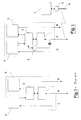
- Fig. 2 schematically shows an SEM in accordance with the invention, together with means for loading software and / or data to the SEM.
- Components in common with the known SEM shown in Fig. 1 retain the same reference numerals.
- a transceiver 5 is located within the SEM, and connected to a port on the processing means 2 for communication therewith.
- the transceiver 5 has an RF input / output coupled, for example capacitively, to the existing modem external interface A.
- the modem interface A wiring functions as an antenna or aerial for the transceiver 5 in use.
- Firmware is stored in the processing means 2, typically in ROM, at manufacture. This enables communication between the transceiver 5 and the processing means 2.
- an external processor 7 is used, which is connected to a wireless transceiver 6.
- the processor 7 may for example be a laptop computer, which carries the software / data required by the SEM.
- Transceiver 6 includes an antenna 8 to effect wireless communication with transceiver 5 via the wiring of modem interface A. In this way, data and / or software can be transmitted at high speed through the wireless interface.
- the efficiency, as an antenna, of the existing modem wiring is relatively poor, it is adequate to permit successful communication, since the antenna 8 of the external transceiver 6 can be placed very close to the interface A during loading.
- an external processor 7 that has wi-fi capability is employed, together with a wi-fi compatible transceiver 5 in the SEM. With this arrangement, the need for a separate transceiver 6 is eliminated.
- Bluetooth (RTM) and wi-fi have been specifically mentioned, any other wireless communication systems and protocols may be used provided that they are capable of handling the necessary volume of data at the required rate for satisfactory operation of the electronics module.
- the present invention may either be used to effect loading of the software in the first instance, or may be used as a back-up arrangement to current methods if necessary.
Description
- This invention relates to a subsea electronics module for a well installation, and a method of loading software to such a module.
- The control of a subsea fluid extraction well is normally effected by a subsea electronic control module (SEM) housed within, or located close to, a subsea control module (SCM) mounted on a well tree, situated on the sea bed at the well head. The SEM is provided with electric power and communications via an umbilical line to a control platform, which may be on a vessel or located on land. Typically, the SEM receives commands via the umbilical communication line to its internal electronics. These are then processed by the SEM, and the resulting electrical outputs are sent to electrically-operated production fluid control valves and / or directional control valves (DCVs) housed in the SCM, which control hydraulic power to hydraulically-operated valves. The SEM also feeds data relating to such operations back to the control platform. Additionally, the SEM electronics handles many other functions, which include the collection and interpretation of data from sensors distributed throughout the production system, such as pressure, temperature, fluid flow, microseismic, oil / water quality and, on more recent systems, compressed video and transmits them back to the control platform. The SEM also houses the electronics required to operate a High Integrity Pipeline Protection System (HIPPS) and the electronics for the communication system, such as modems and routers, or in more modern systems, Ethernet interfaces, as well as communication redundancy.
-
Fig. 1 shows a block diagram of a typical existing SEM. Amodem 1 effects external communication, e.g. to the control platform, through an interface A. Themodem 1 communicates internally to an SEM processing means 2, which implements commands from the control platform in the form of outputs todriver circuits 3. These in turn output a multiplicity of drives to external devices such as DCVs through interfaces B. External inputs from a multiplicity of interfaces C connect to signal conditioningelectronic circuits 4. These external inputs include for example signals from the SCM such as monitoring functions, e.g. pressure and temperature measurements, positions of valves etc which can have a variety of electrical interfaces. Thecircuits 4 convert these electrical inputs into a suitable interface for processing means 2. The processing means 2 then processes the inputs and either effects control of the well via the interfaces B and /or outputs data via themodem 1 back to the control platform through the interface A. For the processing means 2 to operate, it is necessary to load data and software to it. This is carried out during factory testing and installation, and is achieved relatively slowly via themodem 1 through the interface A. - Typically, modem SEMs employ processors / microcontrollers to implement the functions described above which has resulted in very large software packages and data having to be loaded in. It takes typically seven hours to load the software / data on a current SEM, via its communication modem, due to the relatively slow speed of the modem. This has a major effect on both testing times and cost. Furthermore, the costs involved in having to take this length of time on the installation vessel at the point of installation are highly significant. One possible solution to this problem could be to add a high-speed data link to the SEM, but this would mean that an additional connector has to be added to the SCM electronic interface plate. However, with the prevailing trend to provide smaller and lighter well control systems containing SCMs, the surface area of the SCM connector end plate has become minimal and there is typically not enough room to add another connector. Furthermore, such a connector may be an expensive device.
- As other prior art may be mentioned
GB-A-2377131 claim 1. - It is an aim of the present invention to overcome these problems, namely to provide a system which enables rapid loading of software to a SEM, without requiring an additional connector.
- This aim is achieved by incorporating a short range, high frequency, wireless transceiver, such as Bluetooth (RTM), to the internal electronics of a SEM. The existing wires connecting to the internal modem may be utilised as an antenna, and software loaded via this link. Thus no additional connector is required at the SCM end plate and if the carrier frequency of the transceiver is in the GHz region and thus wide band, data and software can be loaded rapidly. Since the electronics of the SEM, including the transceiver, is housed in a metal-screened container, spurious radiation from the transceiver is contained. The current cost of small transceivers such as Bluetooth (RTM) are insignificant compared with the costs involved with the long software / data loading times of existing systems.
- Using the invention, the extensive quantity of software required by the processor in a modem SEM can be loaded in a fraction of the time that it takes to load via the normal modem interface, thus making major savings in time and cost in both the manufacturing and test of the product and its installation.
- In accordance with a first aspect of the present invention there is provided an electronics module for a well installation as set out in the accompanying claims.
- In accordance with a second aspect of the present invention there is provided a method for loading software to a subsea electronics module for a well installation as set out in the accompanying claims.
- The invention will now be described, by way of example, with reference to the accompanying drawings, in which:-
-
Fig. 1 schematically shows a known SEM arrangement; and -
Fig. 2 schematically shows a SEM and loading means in accordance with the present invention. -
Fig. 2 schematically shows an SEM in accordance with the invention, together with means for loading software and / or data to the SEM. Components in common with the known SEM shown inFig. 1 retain the same reference numerals. Atransceiver 5 is located within the SEM, and connected to a port on the processing means 2 for communication therewith. Thetransceiver 5 has an RF input / output coupled, for example capacitively, to the existing modem external interface A. The modem interface A wiring functions as an antenna or aerial for thetransceiver 5 in use. Firmware is stored in the processing means 2, typically in ROM, at manufacture. This enables communication between thetransceiver 5 and the processing means 2. - In order to load the required software and / or data to processing means 2, an
external processor 7 is used, which is connected to awireless transceiver 6. Theprocessor 7 may for example be a laptop computer, which carries the software / data required by the SEM. Transceiver 6 includes anantenna 8 to effect wireless communication withtransceiver 5 via the wiring of modem interface A. In this way, data and / or software can be transmitted at high speed through the wireless interface. - Although the efficiency, as an antenna, of the existing modem wiring is relatively poor, it is adequate to permit successful communication, since the
antenna 8 of theexternal transceiver 6 can be placed very close to the interface A during loading. - In an alternative embodiment of the present invention, not shown, an
external processor 7 that has wi-fi capability is employed, together with a wi-ficompatible transceiver 5 in the SEM. With this arrangement, the need for aseparate transceiver 6 is eliminated. - The above-described embodiments are exemplary only, and various alternatives are possible within the scope of the claims.
- Although Bluetooth (RTM) and wi-fi have been specifically mentioned, any other wireless communication systems and protocols may be used provided that they are capable of handling the necessary volume of data at the required rate for satisfactory operation of the electronics module.
- It is envisaged that the present invention may either be used to effect loading of the software in the first instance, or may be used as a back-up arrangement to current methods if necessary.
Claims (7)
- A subsea electronics module for a well installation, comprising a wireless receiver (5), a modem (1) and associated wiring, characterised in that the receiver (5) is a short range wireless receiver for receiving software from an external source and the modem wiring is connected to the wireless receiver (5) for functioning as an antenna of the wireless receiver (5).
- The module according to claim 1, further comprising processing means (2), and wherein the wireless receiver is connected to the processing means (2) for communication therewith.
- The module according to any preceding claim, wherein the receiver (5) is Bluetooth (RTM) configured.
- The module according to any preceding claim, wherein the wireless receiver has a carrier frequency in the order of GHz.
- The module according to any preceding claim, wherein the wireless receiver (5) is wi-fi compatible.
- A method of loading software to a subsea electronics module for a well installation, comprising the steps of:a) providing a subsea electronics module comprising a short range wireless receiver (5), a modem (1) and associated wiring;b) providing a processor (7), external to the module, connected to wireless transmission means (6);c) loading software from the processor to the module via the wireless transmission means and receiver,wherein the modem wiring functions as an antenna for the wireless receiver.
- The method according to claim 6, wherein the loading step is carried out prior to deployment of the module.
Applications Claiming Priority (1)
| Application Number | Priority Date | Filing Date | Title |
|---|---|---|---|
| GB0714471A GB2451258A (en) | 2007-07-25 | 2007-07-25 | A wireless subsea electronic control module for a well installation |
Publications (3)
| Publication Number | Publication Date |
|---|---|
| EP2019524A2 EP2019524A2 (en) | 2009-01-28 |
| EP2019524A3 EP2019524A3 (en) | 2011-10-19 |
| EP2019524B1 true EP2019524B1 (en) | 2013-08-07 |
Family
ID=38512819
Family Applications (1)
| Application Number | Title | Priority Date | Filing Date |
|---|---|---|---|
| EP08159029.1A Active EP2019524B1 (en) | 2007-07-25 | 2008-06-25 | Electronics module |
Country Status (5)
| Country | Link |
|---|---|
| US (1) | US8692686B2 (en) |
| EP (1) | EP2019524B1 (en) |
| AU (1) | AU2008203344B2 (en) |
| BR (1) | BRPI0802450B8 (en) |
| GB (1) | GB2451258A (en) |
Families Citing this family (4)
| Publication number | Priority date | Publication date | Assignee | Title |
|---|---|---|---|---|
| GB2528527B8 (en) * | 2008-12-18 | 2016-09-21 | Ge Oil & Gas Uk Ltd | Subsea electronic module |
| GB2471496B (en) * | 2009-07-01 | 2013-04-17 | Vetco Gray Controls Ltd | Subsea electronic modules |
| EP2458140A1 (en) * | 2010-11-29 | 2012-05-30 | Vetco Gray Controls Limited | Monitoring a subsea well installation |
| GB2531032B (en) | 2014-10-07 | 2021-01-06 | Aker Solutions Ltd | Subsea electronics module |
Family Cites Families (20)
| Publication number | Priority date | Publication date | Assignee | Title |
|---|---|---|---|---|
| US5523761A (en) * | 1993-01-12 | 1996-06-04 | Trimble Navigation Limited | Differential GPS smart antenna device |
| WO1996041446A1 (en) * | 1995-06-07 | 1996-12-19 | E-Comm Incorporated | System for detecting unauthorized account access |
| US6018501A (en) * | 1997-12-10 | 2000-01-25 | Halliburton Energy Services, Inc. | Subsea repeater and method for use of the same |
| US7740099B2 (en) * | 1999-06-04 | 2010-06-22 | Segway Inc. | Enhanced control of a transporter |
| US6364021B1 (en) * | 2000-07-11 | 2002-04-02 | Halliburton Energy Services, Inc. | Well management system and method of operation |
| US6438468B1 (en) * | 2000-11-28 | 2002-08-20 | Honeywell International Inc. | Systems and methods for delivering data updates to an aircraft |
| US7908042B2 (en) * | 2001-02-13 | 2011-03-15 | The Boeing Company | Methods and apparatus for wireless upload and download of aircraft data |
| US7123162B2 (en) * | 2001-04-23 | 2006-10-17 | Schlumberger Technology Corporation | Subsea communication system and technique |
| GB2396086C (en) * | 2002-12-03 | 2007-11-02 | Vetco Gray Controls Ltd | A system for use in controlling a hydrocarbon production well |
| GB2400687B (en) * | 2003-04-16 | 2005-04-06 | Schlumberger Holdings | Acquisition and control system |
| US7261162B2 (en) * | 2003-06-25 | 2007-08-28 | Schlumberger Technology Corporation | Subsea communications system |
| US7532640B2 (en) * | 2003-07-02 | 2009-05-12 | Caterpillar Inc. | Systems and methods for performing protocol conversions in a machine |
| EP1522921A1 (en) | 2003-10-07 | 2005-04-13 | Service Pétroliers Schlumberger | Method and apparatus for dynamic application management in sub-sea well installations |
| NO323785B1 (en) * | 2004-02-18 | 2007-07-09 | Fmc Kongsberg Subsea As | Power Generation System |
| SG120314A1 (en) * | 2004-09-02 | 2006-03-28 | Vetco Gray Inc | Tubing running equipment for offshore rig with surface blowout preventer |
| US7477160B2 (en) * | 2004-10-27 | 2009-01-13 | Schlumberger Technology Corporation | Wireless communications associated with a wellbore |
| GB2421524B (en) * | 2004-12-22 | 2009-06-24 | Vetco Gray Controls Ltd | Hydraulic control system |
| US7509121B2 (en) * | 2005-04-18 | 2009-03-24 | Terax Communication Technologies Inc. | Method of updating firmware using object push profile in the bluetooth object exchange protocol |
| US7748450B2 (en) * | 2005-12-19 | 2010-07-06 | Mundell Bret M | Gas wellhead extraction system and method |
| US20080002758A1 (en) * | 2006-06-28 | 2008-01-03 | Infineon Technologies Ag | Communications device and method for changing utilization data |
-
2007
- 2007-07-25 GB GB0714471A patent/GB2451258A/en not_active Withdrawn
-
2008
- 2008-06-25 EP EP08159029.1A patent/EP2019524B1/en active Active
- 2008-07-08 US US12/217,636 patent/US8692686B2/en active Active
- 2008-07-25 AU AU2008203344A patent/AU2008203344B2/en active Active
- 2008-07-25 BR BRPI0802450A patent/BRPI0802450B8/en not_active IP Right Cessation
Also Published As
| Publication number | Publication date |
|---|---|
| EP2019524A2 (en) | 2009-01-28 |
| BRPI0802450A2 (en) | 2009-03-17 |
| US20090031297A1 (en) | 2009-01-29 |
| US8692686B2 (en) | 2014-04-08 |
| GB2451258A (en) | 2009-01-28 |
| BRPI0802450B8 (en) | 2018-10-16 |
| AU2008203344B2 (en) | 2013-05-16 |
| AU2008203344A1 (en) | 2009-02-12 |
| GB0714471D0 (en) | 2007-09-05 |
| BRPI0802450A8 (en) | 2018-06-12 |
| EP2019524A3 (en) | 2011-10-19 |
Similar Documents
| Publication | Publication Date | Title |
|---|---|---|
| US8581741B2 (en) | Communication system for a hydrocarbon extraction plant | |
| EP2019524B1 (en) | Electronics module | |
| EP1916868B1 (en) | Smart wireless engine sensor | |
| US10949372B2 (en) | Systems and methods for data communication | |
| EP3116064B1 (en) | Method and device for implementing antenna modularization and antenna modules | |
| US20120175122A1 (en) | Electronics module | |
| CN105227203A (en) | A kind of airborne middle rf data terminal and method | |
| EP2019525A2 (en) | Electronics card communication | |
| US7769915B1 (en) | Systems and method of controlling control and/or monitoring devices | |
| CN112910542A (en) | Measure and control ground detection equipment and system | |
| EP3163013B1 (en) | Subsea communication adapter | |
| CN115865116B (en) | Unmanned equipment comprehensive lead integrated system and equipment | |
| AU2014270120A1 (en) | Aircraft data retrieval | |
| GB2459488A (en) | Wired communication with acoustic communication backup | |
| US10687389B2 (en) | Wireless industrial remote controller for industrial process control and automation systems or other systems | |
| US9803471B2 (en) | Safety signals | |
| WO2020205709A1 (en) | Systems and methods for radar detection | |
| CN105406885A (en) | Automatic ship identification system adopting radio frequency (RF) agile transceiver AD9361 and configuration method | |
| US20210160095A1 (en) | Communication System for Providing Communication Between a Control Module and an Oil and/or Gas Module | |
| US20140337827A1 (en) | Method of reducing downtime of production controls during upgrades | |
| CN107797494A (en) | A kind of leaky feeder communication control circuit | |
| CN112929344A (en) | System for upgrading equipment through Internet of things adapter and Internet of things adapter | |
| GB2514400A (en) | Aircraft data retrieval | |
| CN104506254A (en) | High-power channel process equipment with self functionality checking function | |
| CN102420629A (en) | Underground wireless communication tool |
Legal Events
| Date | Code | Title | Description |
|---|---|---|---|
| PUAI | Public reference made under article 153(3) epc to a published international application that has entered the european phase |
Free format text: ORIGINAL CODE: 0009012 |
|
| AK | Designated contracting states |
Kind code of ref document: A2 Designated state(s): AT BE BG CH CY CZ DE DK EE ES FI FR GB GR HR HU IE IS IT LI LT LU LV MC MT NL NO PL PT RO SE SI SK TR |
|
| AX | Request for extension of the european patent |
Extension state: AL BA MK RS |
|
| PUAL | Search report despatched |
Free format text: ORIGINAL CODE: 0009013 |
|
| AK | Designated contracting states |
Kind code of ref document: A3 Designated state(s): AT BE BG CH CY CZ DE DK EE ES FI FR GB GR HR HU IE IS IT LI LT LU LV MC MT NL NO PL PT RO SE SI SK TR |
|
| AX | Request for extension of the european patent |
Extension state: AL BA MK RS |
|
| RIC1 | Information provided on ipc code assigned before grant |
Ipc: H04B 1/38 20060101ALI20110913BHEP Ipc: H04L 12/56 20060101AFI20110913BHEP Ipc: E21B 33/02 20060101ALI20110913BHEP Ipc: H04B 1/18 20060101ALI20110913BHEP |
|
| 17P | Request for examination filed |
Effective date: 20120419 |
|
| AKX | Designation fees paid |
Designated state(s): DE FR GB NO |
|
| 17Q | First examination report despatched |
Effective date: 20121010 |
|
| REG | Reference to a national code |
Ref country code: DE Ref legal event code: R079 Ref document number: 602008026553 Country of ref document: DE Free format text: PREVIOUS MAIN CLASS: H04L0012560000 Ipc: E21B0033035000 |
|
| GRAP | Despatch of communication of intention to grant a patent |
Free format text: ORIGINAL CODE: EPIDOSNIGR1 |
|
| RIC1 | Information provided on ipc code assigned before grant |
Ipc: E21B 33/035 20060101AFI20130109BHEP Ipc: H04B 1/18 20060101ALI20130109BHEP |
|
| GRAS | Grant fee paid |
Free format text: ORIGINAL CODE: EPIDOSNIGR3 |
|
| GRAA | (expected) grant |
Free format text: ORIGINAL CODE: 0009210 |
|
| AK | Designated contracting states |
Kind code of ref document: B1 Designated state(s): DE FR GB NO |
|
| REG | Reference to a national code |
Ref country code: GB Ref legal event code: FG4D |
|
| REG | Reference to a national code |
Ref country code: DE Ref legal event code: R096 Ref document number: 602008026553 Country of ref document: DE Effective date: 20131002 |
|
| REG | Reference to a national code |
Ref country code: NO Ref legal event code: T2 Effective date: 20130807 |
|
| PLBE | No opposition filed within time limit |
Free format text: ORIGINAL CODE: 0009261 |
|
| STAA | Information on the status of an ep patent application or granted ep patent |
Free format text: STATUS: NO OPPOSITION FILED WITHIN TIME LIMIT |
|
| 26N | No opposition filed |
Effective date: 20140508 |
|
| REG | Reference to a national code |
Ref country code: DE Ref legal event code: R097 Ref document number: 602008026553 Country of ref document: DE Effective date: 20140508 |
|
| REG | Reference to a national code |
Ref country code: DE Ref legal event code: R082 Ref document number: 602008026553 Country of ref document: DE Representative=s name: RUEGER | ABEL PATENT- UND RECHTSANWAELTE, DE Ref country code: DE Ref legal event code: R082 Ref document number: 602008026553 Country of ref document: DE Representative=s name: RUEGER, BARTHELT & ABEL PATENTANWAELTE, DE Ref country code: DE Ref legal event code: R082 Ref document number: 602008026553 Country of ref document: DE Representative=s name: RUEGER ABEL PATENT- UND RECHTSANWAELTE, DE |
|
| REG | Reference to a national code |
Ref country code: DE Ref legal event code: R082 Ref document number: 602008026553 Country of ref document: DE Representative=s name: RUEGER | ABEL PATENT- UND RECHTSANWAELTE, DE Ref country code: DE Ref legal event code: R082 Ref document number: 602008026553 Country of ref document: DE Representative=s name: RUEGER, BARTHELT & ABEL PATENTANWAELTE, DE Ref country code: DE Ref legal event code: R081 Ref document number: 602008026553 Country of ref document: DE Owner name: GE OIL & GAS UK LTD., GB Free format text: FORMER OWNER: VETCO GRAY CONTROLS LIMITED, BRISTOL, NAILSEA, GB Ref country code: DE Ref legal event code: R082 Ref document number: 602008026553 Country of ref document: DE Representative=s name: RUEGER ABEL PATENT- UND RECHTSANWAELTE, DE |
|
| REG | Reference to a national code |
Ref country code: FR Ref legal event code: PLFP Year of fee payment: 8 |
|
| REG | Reference to a national code |
Ref country code: NO Ref legal event code: CHAD Owner name: GE OIL & GAS UK LIMITED, GB |
|
| REG | Reference to a national code |
Ref country code: FR Ref legal event code: TP Owner name: GE OIL & GAS UK LIMITED, GB Effective date: 20151116 |
|
| REG | Reference to a national code |
Ref country code: FR Ref legal event code: PLFP Year of fee payment: 9 |
|
| REG | Reference to a national code |
Ref country code: FR Ref legal event code: PLFP Year of fee payment: 10 |
|
| REG | Reference to a national code |
Ref country code: FR Ref legal event code: PLFP Year of fee payment: 11 |
|
| PGFP | Annual fee paid to national office [announced via postgrant information from national office to epo] |
Ref country code: FR Payment date: 20220519 Year of fee payment: 15 |
|
| PGFP | Annual fee paid to national office [announced via postgrant information from national office to epo] |
Ref country code: NO Payment date: 20230525 Year of fee payment: 16 Ref country code: DE Payment date: 20230523 Year of fee payment: 16 |
|
| PGFP | Annual fee paid to national office [announced via postgrant information from national office to epo] |
Ref country code: GB Payment date: 20230523 Year of fee payment: 16 |