EP2019443A1 - Solid bonded interconnect system in a solid oxide fuel cell stack - Google Patents
Solid bonded interconnect system in a solid oxide fuel cell stack Download PDFInfo
- Publication number
- EP2019443A1 EP2019443A1 EP08157881A EP08157881A EP2019443A1 EP 2019443 A1 EP2019443 A1 EP 2019443A1 EP 08157881 A EP08157881 A EP 08157881A EP 08157881 A EP08157881 A EP 08157881A EP 2019443 A1 EP2019443 A1 EP 2019443A1
- Authority
- EP
- European Patent Office
- Prior art keywords
- cathode
- separator plate
- anode
- accordance
- interconnect
- Prior art date
- Legal status (The legal status is an assumption and is not a legal conclusion. Google has not performed a legal analysis and makes no representation as to the accuracy of the status listed.)
- Ceased
Links
- 239000000446 fuel Substances 0.000 title claims abstract description 35
- 239000007787 solid Substances 0.000 title claims description 8
- 229910052751 metal Inorganic materials 0.000 claims abstract description 24
- 239000002184 metal Substances 0.000 claims abstract description 24
- BQCADISMDOOEFD-UHFFFAOYSA-N Silver Chemical compound [Ag] BQCADISMDOOEFD-UHFFFAOYSA-N 0.000 claims abstract description 15
- 229910052709 silver Inorganic materials 0.000 claims abstract description 15
- 239000004332 silver Substances 0.000 claims abstract description 15
- 229910001316 Ag alloy Inorganic materials 0.000 claims description 11
- 229910045601 alloy Inorganic materials 0.000 claims description 7
- 239000000956 alloy Substances 0.000 claims description 7
- 229910001220 stainless steel Inorganic materials 0.000 claims description 6
- KDLHZDBZIXYQEI-UHFFFAOYSA-N Palladium Chemical compound [Pd] KDLHZDBZIXYQEI-UHFFFAOYSA-N 0.000 claims description 5
- PXHVJJICTQNCMI-UHFFFAOYSA-N Nickel Chemical compound [Ni] PXHVJJICTQNCMI-UHFFFAOYSA-N 0.000 claims description 4
- 239000000463 material Substances 0.000 claims description 4
- 229910052763 palladium Inorganic materials 0.000 claims description 3
- 229910052759 nickel Inorganic materials 0.000 claims 1
- 230000013011 mating Effects 0.000 abstract description 3
- 229910000480 nickel oxide Inorganic materials 0.000 abstract description 2
- GNRSAWUEBMWBQH-UHFFFAOYSA-N oxonickel Chemical compound [Ni]=O GNRSAWUEBMWBQH-UHFFFAOYSA-N 0.000 abstract description 2
- 210000004027 cell Anatomy 0.000 description 65
- 239000010410 layer Substances 0.000 description 18
- 238000005382 thermal cycling Methods 0.000 description 10
- 239000007789 gas Substances 0.000 description 5
- 238000000034 method Methods 0.000 description 5
- 230000008569 process Effects 0.000 description 5
- 239000000919 ceramic Substances 0.000 description 4
- 239000011248 coating agent Substances 0.000 description 4
- 238000000576 coating method Methods 0.000 description 4
- 239000011651 chromium Substances 0.000 description 3
- 239000003792 electrolyte Substances 0.000 description 3
- 239000002737 fuel gas Substances 0.000 description 3
- 230000006870 function Effects 0.000 description 3
- 231100000572 poisoning Toxicity 0.000 description 3
- 230000000607 poisoning effect Effects 0.000 description 3
- 238000005245 sintering Methods 0.000 description 3
- VYZAMTAEIAYCRO-UHFFFAOYSA-N Chromium Chemical compound [Cr] VYZAMTAEIAYCRO-UHFFFAOYSA-N 0.000 description 2
- 230000008901 benefit Effects 0.000 description 2
- 239000004020 conductor Substances 0.000 description 2
- 230000006378 damage Effects 0.000 description 2
- 238000009792 diffusion process Methods 0.000 description 2
- 238000004519 manufacturing process Methods 0.000 description 2
- 239000000843 powder Substances 0.000 description 2
- 239000000853 adhesive Substances 0.000 description 1
- 230000001070 adhesive effect Effects 0.000 description 1
- 230000000712 assembly Effects 0.000 description 1
- 238000000429 assembly Methods 0.000 description 1
- QVGXLLKOCUKJST-UHFFFAOYSA-N atomic oxygen Chemical compound [O] QVGXLLKOCUKJST-UHFFFAOYSA-N 0.000 description 1
- 230000004888 barrier function Effects 0.000 description 1
- 238000005452 bending Methods 0.000 description 1
- 230000015572 biosynthetic process Effects 0.000 description 1
- 210000003850 cellular structure Anatomy 0.000 description 1
- 229910052804 chromium Inorganic materials 0.000 description 1
- 229910017052 cobalt Inorganic materials 0.000 description 1
- 239000010941 cobalt Substances 0.000 description 1
- GUTLYIVDDKVIGB-UHFFFAOYSA-N cobalt atom Chemical compound [Co] GUTLYIVDDKVIGB-UHFFFAOYSA-N 0.000 description 1
- 230000001010 compromised effect Effects 0.000 description 1
- 239000000356 contaminant Substances 0.000 description 1
- 239000011521 glass Substances 0.000 description 1
- 239000001257 hydrogen Substances 0.000 description 1
- 229910052739 hydrogen Inorganic materials 0.000 description 1
- 125000004435 hydrogen atom Chemical class [H]* 0.000 description 1
- 229910052746 lanthanum Inorganic materials 0.000 description 1
- FZLIPJUXYLNCLC-UHFFFAOYSA-N lanthanum atom Chemical compound [La] FZLIPJUXYLNCLC-UHFFFAOYSA-N 0.000 description 1
- 230000007774 longterm Effects 0.000 description 1
- 238000002844 melting Methods 0.000 description 1
- 230000008018 melting Effects 0.000 description 1
- 150000002739 metals Chemical class 0.000 description 1
- 239000000203 mixture Substances 0.000 description 1
- 238000010943 off-gassing Methods 0.000 description 1
- 239000011368 organic material Substances 0.000 description 1
- 230000001590 oxidative effect Effects 0.000 description 1
- 239000001301 oxygen Substances 0.000 description 1
- 229910052760 oxygen Inorganic materials 0.000 description 1
- 239000002245 particle Substances 0.000 description 1
- 230000009467 reduction Effects 0.000 description 1
- 230000000284 resting effect Effects 0.000 description 1
- 230000035939 shock Effects 0.000 description 1
- 125000006850 spacer group Chemical group 0.000 description 1
- 229910052712 strontium Inorganic materials 0.000 description 1
- CIOAGBVUUVVLOB-UHFFFAOYSA-N strontium atom Chemical compound [Sr] CIOAGBVUUVVLOB-UHFFFAOYSA-N 0.000 description 1
- 239000002344 surface layer Substances 0.000 description 1
- 239000010409 thin film Substances 0.000 description 1
- XLYOFNOQVPJJNP-UHFFFAOYSA-N water Substances O XLYOFNOQVPJJNP-UHFFFAOYSA-N 0.000 description 1
Images

Classifications
-
- H—ELECTRICITY
- H01—ELECTRIC ELEMENTS
- H01M—PROCESSES OR MEANS, e.g. BATTERIES, FOR THE DIRECT CONVERSION OF CHEMICAL ENERGY INTO ELECTRICAL ENERGY
- H01M8/00—Fuel cells; Manufacture thereof
- H01M8/02—Details
- H01M8/0202—Collectors; Separators, e.g. bipolar separators; Interconnectors
- H01M8/0204—Non-porous and characterised by the material
- H01M8/0223—Composites
- H01M8/0228—Composites in the form of layered or coated products
-
- H—ELECTRICITY
- H01—ELECTRIC ELEMENTS
- H01M—PROCESSES OR MEANS, e.g. BATTERIES, FOR THE DIRECT CONVERSION OF CHEMICAL ENERGY INTO ELECTRICAL ENERGY
- H01M8/00—Fuel cells; Manufacture thereof
- H01M8/02—Details
- H01M8/0202—Collectors; Separators, e.g. bipolar separators; Interconnectors
- H01M8/023—Porous and characterised by the material
- H01M8/0241—Composites
- H01M8/0245—Composites in the form of layered or coated products
-
- H—ELECTRICITY
- H01—ELECTRIC ELEMENTS
- H01M—PROCESSES OR MEANS, e.g. BATTERIES, FOR THE DIRECT CONVERSION OF CHEMICAL ENERGY INTO ELECTRICAL ENERGY
- H01M8/00—Fuel cells; Manufacture thereof
- H01M8/02—Details
- H01M8/0202—Collectors; Separators, e.g. bipolar separators; Interconnectors
- H01M8/0258—Collectors; Separators, e.g. bipolar separators; Interconnectors characterised by the configuration of channels, e.g. by the flow field of the reactant or coolant
-
- H—ELECTRICITY
- H01—ELECTRIC ELEMENTS
- H01M—PROCESSES OR MEANS, e.g. BATTERIES, FOR THE DIRECT CONVERSION OF CHEMICAL ENERGY INTO ELECTRICAL ENERGY
- H01M8/00—Fuel cells; Manufacture thereof
- H01M8/02—Details
- H01M8/0271—Sealing or supporting means around electrodes, matrices or membranes
-
- H—ELECTRICITY
- H01—ELECTRIC ELEMENTS
- H01M—PROCESSES OR MEANS, e.g. BATTERIES, FOR THE DIRECT CONVERSION OF CHEMICAL ENERGY INTO ELECTRICAL ENERGY
- H01M8/00—Fuel cells; Manufacture thereof
- H01M8/02—Details
- H01M8/0271—Sealing or supporting means around electrodes, matrices or membranes
- H01M8/0273—Sealing or supporting means around electrodes, matrices or membranes with sealing or supporting means in the form of a frame
-
- H—ELECTRICITY
- H01—ELECTRIC ELEMENTS
- H01M—PROCESSES OR MEANS, e.g. BATTERIES, FOR THE DIRECT CONVERSION OF CHEMICAL ENERGY INTO ELECTRICAL ENERGY
- H01M8/00—Fuel cells; Manufacture thereof
- H01M8/24—Grouping of fuel cells, e.g. stacking of fuel cells
- H01M8/241—Grouping of fuel cells, e.g. stacking of fuel cells with solid or matrix-supported electrolytes
- H01M8/2425—High-temperature cells with solid electrolytes
- H01M8/2432—Grouping of unit cells of planar configuration
-
- H—ELECTRICITY
- H01—ELECTRIC ELEMENTS
- H01M—PROCESSES OR MEANS, e.g. BATTERIES, FOR THE DIRECT CONVERSION OF CHEMICAL ENERGY INTO ELECTRICAL ENERGY
- H01M8/00—Fuel cells; Manufacture thereof
- H01M8/10—Fuel cells with solid electrolytes
- H01M8/12—Fuel cells with solid electrolytes operating at high temperature, e.g. with stabilised ZrO2 electrolyte
- H01M2008/1293—Fuel cells with solid oxide electrolytes
-
- H—ELECTRICITY
- H01—ELECTRIC ELEMENTS
- H01M—PROCESSES OR MEANS, e.g. BATTERIES, FOR THE DIRECT CONVERSION OF CHEMICAL ENERGY INTO ELECTRICAL ENERGY
- H01M8/00—Fuel cells; Manufacture thereof
- H01M8/02—Details
- H01M8/0202—Collectors; Separators, e.g. bipolar separators; Interconnectors
- H01M8/0204—Non-porous and characterised by the material
- H01M8/0206—Metals or alloys
- H01M8/0208—Alloys
- H01M8/021—Alloys based on iron
-
- H—ELECTRICITY
- H01—ELECTRIC ELEMENTS
- H01M—PROCESSES OR MEANS, e.g. BATTERIES, FOR THE DIRECT CONVERSION OF CHEMICAL ENERGY INTO ELECTRICAL ENERGY
- H01M8/00—Fuel cells; Manufacture thereof
- H01M8/02—Details
- H01M8/0202—Collectors; Separators, e.g. bipolar separators; Interconnectors
- H01M8/023—Porous and characterised by the material
- H01M8/0232—Metals or alloys
-
- Y—GENERAL TAGGING OF NEW TECHNOLOGICAL DEVELOPMENTS; GENERAL TAGGING OF CROSS-SECTIONAL TECHNOLOGIES SPANNING OVER SEVERAL SECTIONS OF THE IPC; TECHNICAL SUBJECTS COVERED BY FORMER USPC CROSS-REFERENCE ART COLLECTIONS [XRACs] AND DIGESTS
- Y02—TECHNOLOGIES OR APPLICATIONS FOR MITIGATION OR ADAPTATION AGAINST CLIMATE CHANGE
- Y02E—REDUCTION OF GREENHOUSE GAS [GHG] EMISSIONS, RELATED TO ENERGY GENERATION, TRANSMISSION OR DISTRIBUTION
- Y02E60/00—Enabling technologies; Technologies with a potential or indirect contribution to GHG emissions mitigation
- Y02E60/30—Hydrogen technology
- Y02E60/50—Fuel cells
Definitions
- the output of a single fuel cell is typically less than one volt, so connecting multiple cells in series is required to achieve useful operating voltages.
- a plurality of fuel cells are mechanically stacked up in a "stack" and are electrically connected in series from the anode of one cell to the cathode of an adjacent cell via intermediate stack elements known in the art as "interconnects".
- the interconnect In an SOFC stack, the interconnect must perform a variety of functions, including:
- the cathode in a SOFC cell needs to have good electrical contact with the metallic interconnect mesh or other flow feature in the cathode side of the repeating unit. This contact is achieved typically by using a conductive paste but it needs to be low resistance, have compatibility with the cell component, and be durable at the SOFC operating temperatures.
- Typical prior art SOFC interconnects have perovskites or silver paste as the contact paste between the cathode and the metal interconnect.
- Perovskite pastes have a drawback in that they sinter to a brittle ceramic, leading to cracked contact interfaces which lead to higher resistance over time and thermal cycling.
- an interconnect system for mechanically and electrically connecting adjacent fuel cells in a fuel cell stack comprises five elements: a separator plate to provide an anode gas flow space when joined to a mating cell frame and to provide electrical connection between the anode and the cathode; a first metal interconnect disposed between the separator plate and the anode surface; a nickel oxide paste applied in a pattern over the surface of the anode and adjacent surface of the separator plate which when sintered results in a metal layer bonded to the anode and to the separator plate; a second metal interconnect disposed between the cathode surface of the cell and the separator plate of the adjacent cell cassette; and a silver alloy paste applied over the surface of the cathode and the separator plate which when sintered results in a metal layer bonded to the cathode and to the separator plate.
- an exemplary SOFC fuel cell 10 comprises a cathode layer 12, an electrolyte layer 14 formed of a solid oxide and bonded to the cathode layer 12, and an anode layer 16 bonded to the electrolyte layer 14 on a side opposite from the cathode layer.
- air 18 is passed over the surface 34 of the cathode layer 12, and oxygen from the air migrates through the electrolyte layer 14 and reacts in the anode layer 16 with hydrogen 20 being passed over the anode surface layer 31 to form water, thereby creating an electrical potential between the anode and the cathode, typically of about 1 volt.
- fuel cell 10 is mounted, for handling, protection, and assembly into a stack, within a metal frame 22 referred to in the art as a "picture frame", to form a "cell-picture frame assembly" 24.
- a presently-preferred intermediate process joins together a cell-picture frame assembly 24 with a separator plate 28 and a first solid (anode) interconnect 30 to form an intermediate structure known as a fuel cell cassette 32 ("cassette").
- the thin sheet metal separator plate 28 is stamped and formed to provide, when joined to the mating cell frame 22 and anode spacers 29, a flow space 23 for the anode gas 20.
- the separator plate 28 is formed of ferritic stainless steel for low cost, and is coated on the side facing the cathode with a thin layer of conductive material that will prevent Cr poisoning of the cathode in the assembled stack.
- This coating is typically a perovskite such as LSC (lanthanum, strontium, cobalt).
- First anode interconnect 30 is placed between the separator plate 28 and the anode surface 31 of the cell within the cassette 32.
- the anode interconnect 30 can be a woven wire mesh, a sheet metal part with photochemically machined flow passages and contact points, or other parts that are of uniform thickness but solid in the direction perpendicular to the cell surface in a multitude of points.
- the thickness of this part is slightly less than the as-formed space available within the cassette; this prevents interference due to tolerances when assembling the cassette at room temperature.
- the separator plate will creep to the proper dimension during the final step of stack assembly.
- NiO paste 38 is screen printed in a pattern to the separator plate 28 and the anode surface 31 of the cell 24. The resulting Ni particles, when reduced by high temperature during stack assembly, diffusion bond to the separator plate 28, anode interconnect 30, and anode surface 31 of the cell. This bond provides a mechanically robust joint that will endure thermal cycling and has minimal electrical contact resistance.
- a thin film of paste containing silver or silver alloy is applied uniformly to the top surface 34 of the cell cathode layer during cell fabrication and is sintered at elevated temperature to the cathode as part of the cell fabrication process.
- thin layer 39 of microscopically porous sintered silver or silver alloy will be tightly adhered to the cathode surface 34.
- This metallic layer 39 provides excellent electrical contact with the cathode, and enables a metallurgically bonded contact with metallic contact paste in the stack assembly.
- This layer has been found to add long-term operational stability to the cell, and provides a metallic surface for joining the cathode interconnect 35. This bond provides a conductive and mechanically robust joint that will endure thermal cycling and has minimal contact resistance.
- This metallic cap layer 39 can also be used as a barrier coating for contaminants that can potentially harm the cathode.
- An alloy comprising 80-90% Ag and 20-10% Pd is a very effective conductive paste for the cathode to the interconnect. This alloy has all the benefits of high conductivity and good mechanical adhesion to the cathode as well as stability at the SOFC operating temperatures.
- the cathode interconnect 35 installed during final assembly against the cathode, provides a cathode air flow space 37.
- Interconnect 35 also can be a woven wire mesh, a sheet metal part with photochemically machined flow passages and contact points, or other parts that are of uniform thickness but solid in the direction perpendicular to the cell surface in a multitude of points.
- a woven wire mesh fabricated from an alumina-forming ferritic stainless steel alloy (a FeCrAlloy type of material) is presently preferred.
- the alumina-forming alloy prevents chromium poisoning of the cathode by outgassing of chrome from the ferritic stainless steel but has very poor surface conductivity in an oxidizing environment, so it is plated with a thin layer of silver.
- the silver provides the conductive path between the cathode and the next separator plate, and the wire mesh provides the mechanical structure.
- other interconnect parts can be formed in a similar fashion as an alumina-forming structure plated with silver. These interconnect parts 30,35 have a good Coefficient of Thermal Expansion (CTE) match to the cells 24, which minimizes in-plane shear forces.
- CTE Coefficient of Thermal Expansion
- the cathode interconnect 35 is placed between the separator plate 28 and the cathode of the cell of the adjoining cassette.
- Silver or silver alloy paste 36 is screen printed in a pattern to the separator plate 28 and to the thin metallic coating 39 on cathode surface 34 of the cell 24 of the adjoining cassette.
- the silver or silver alloy powders in the contact paste when sintered by high temperature during stack assembly, diffusion bond to the separator plate 28, cathode interconnect 35, and the metallic coating 39 on the cathode surface 34 of the cell. This bond provides a mechanically robust joint that will endure thermal cycling and has minimal electrical contact resistance.
- each contact point makes up an area of about 0.01 mm 2 to 5.0mm 2 and the points are spaced between about 0.5mm and 5.0mm apart.
- the metallic contact pastes on both sides of the cell not only make a metallurgically bonded contact joint, but also fill in the micro irregularities of the cell surface providing good mechanical support to the cell.
- an improved interconnect system in accordance with the invention has the following advantages over prior art interconnect systems:
Landscapes
- Chemical & Material Sciences (AREA)
- Life Sciences & Earth Sciences (AREA)
- Engineering & Computer Science (AREA)
- Manufacturing & Machinery (AREA)
- Sustainable Development (AREA)
- Sustainable Energy (AREA)
- Chemical Kinetics & Catalysis (AREA)
- Electrochemistry (AREA)
- General Chemical & Material Sciences (AREA)
- Composite Materials (AREA)
- Fuel Cell (AREA)
Abstract
Description
- The present invention relates to solid oxide fuel cell (SOFC) stacks; more particularly, to interconnects for connecting adjacent fuel cells electrically and mechanically; and most particularly, to an improved interconnect system for such purpose that provides an SOFC stack that is mechanically and electrically robust.
- In practical fuel cell systems, the output of a single fuel cell is typically less than one volt, so connecting multiple cells in series is required to achieve useful operating voltages. Typically, a plurality of fuel cells are mechanically stacked up in a "stack" and are electrically connected in series from the anode of one cell to the cathode of an adjacent cell via intermediate stack elements known in the art as "interconnects".
- In an SOFC stack, the interconnect must perform a variety of functions, including:
- Low resistance electrical contact at operating temperatures of 500°C to 1000°C, operating for tens of thousands of hours;
- Robust connection that endures vibration, shock, and thermal cycling;
- Separator plate, in the case of a planar SOFC stack, to prevent intermixing of the anode fuel gas stream for one cell with the cathode air stream of the adjoining cell; current must pass through the separator plate;
- Must be porous or have passages that allow access of the anode fuel gas and the cathode air to their respective surfaces of the cell;
- In some cases, the interconnect also provides mechanical support to the cell.
- Various forms of interconnect systems are known in the prior art:
- A rigid mounting plate that incorporates the anode gas and cathode air passages and separator plate function. Contact is made to the cell with contact paste comprising NiO which reduces to Ni in operation on the anode side, and conductive ceramic pastes on the cathode side. These types of interconnects typically are heavy, complex to fabricate, and expensive. There is also very little conformance between parts at operating temperatures, which can induce stress into the cells, leading to fracture resulting in loss of function. In addition, since parts are rigid, there is no allowance for relative motion during thermal cycling which will stress the cell and fracture the contact paste bonds, resulting in poor connection.
- A very flexible connecting filament system. In this type of system, no mechanical support is provided for the cell by the interconnect. The cell is allowed to float, which theoretically reduces stress in the cell. Adhesive contact is made between the filaments and the cell with NiO and conductive pastes similar to the above. This type of system results in tremendous variation in the shape and size of the anode fuel gas and cathode air stream passages, which leads to large variations in gas flow, and therefore performance, from one cell to the next. Also, since the cell is actually quite flexible at operating temperatures, it will take shapes that are non-planar. It has been shown, by finite element analysis and in practice, that this can actually result in higher cell stress and a propensity to fracture, particularly during thermal cycling.
- A connection system comprising springy formed wire or sheet strips. The intent of this type of interconnect scheme is not only to provide some support for the cell, but also to provide some compliance for surface irregularities and relative motion during thermal cycling. Contact pastes similar to those above are used, although adhesion is not required. A problem with this system is that there will always be slight mismatches in spring forces exerted on the cell, and these mismatches will vary across the cell surface, resulting in localized bending forces and therefore stress in the cell which can lead to fracture. In addition, although the interconnect is compliant, there are still shear forces which can fracture the fragile cathode conductive ceramic paste joint which will still make contact, but at increased electrical resistance.
- A thin metal separator plate that has dimples or ribs formed into it for contact with the anode and cathode. Contact pastes as above typically are used. This type of structure is very economical but has several drawbacks. Due to sheet metal forming limitations and the necessary restriction in geometry by using one part, the number, shape, and positions of the contact points are severely compromised. Also, if the plate material is ferritic stainless steel, which is a good choice for low cost and thermal expansion matching to the cell, the plate has very little strength at operating temperatures and the formed-in features will creep, resulting in a reduction of contact and loss in positioning of the cell. If a stronger alloy is used, it will have a thermal expansion mismatch, resulting in severe shear forces that can fracture the contact paste joints, leading to an increase in resistance. Also, there will be mismatched contact forces similar to those in the springy contact system.
- The cathode in a SOFC cell needs to have good electrical contact with the metallic interconnect mesh or other flow feature in the cathode side of the repeating unit. This contact is achieved typically by using a conductive paste but it needs to be low resistance, have compatibility with the cell component, and be durable at the SOFC operating temperatures.
- Typical prior art SOFC interconnects have perovskites or silver paste as the contact paste between the cathode and the metal interconnect. Perovskite pastes have a drawback in that they sinter to a brittle ceramic, leading to cracked contact interfaces which lead to higher resistance over time and thermal cycling. Silver paste is a very good conductor and can form a low resistance contact but it has the drawback in that it is volatile at the operating temperature of SOFC (m.p = 961 °C) and can cause potential damage to the stack (shorts etc).
- What is needed in the art is an interconnect system that provides a mechanically robust joint between itself and adjacent fuel cells that will endure thermal cycling and has minimal electrical contact resistance.
- It is a principal object of the present invention to increase the reliability and durability of an SOFC system.
- Briefly described, an interconnect system for mechanically and electrically connecting adjacent fuel cells in a fuel cell stack comprises five elements: a separator plate to provide an anode gas flow space when joined to a mating cell frame and to provide electrical connection between the anode and the cathode; a first metal interconnect disposed between the separator plate and the anode surface; a nickel oxide paste applied in a pattern over the surface of the anode and adjacent surface of the separator plate which when sintered results in a metal layer bonded to the anode and to the separator plate; a second metal interconnect disposed between the cathode surface of the cell and the separator plate of the adjacent cell cassette; and a silver alloy paste applied over the surface of the cathode and the separator plate which when sintered results in a metal layer bonded to the cathode and to the separator plate.
- The present invention will now be described, by way of example, with reference to the accompanying drawings, in which:
-
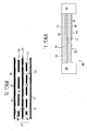
FIG. 1 is a schematic cross-sectional view of a fuel cell, after sintering, mounted in a picture-frame as a picture-frame assembly; -
FIG. 2 is a schematic cross-sectional view of an interconnect system in accordance with the invention disposed between adjacent picture-frame assemblies in a fuel cell stack; and -
FIG. 3 is a exploded isometric view showing three fuel cell cassettes in accordance with the invention in a fuel cell stack. - Corresponding reference characters indicate corresponding parts throughout the several views. The exemplification set out herein illustrates one preferred embodiment of the invention, in one form, and such exemplification is not to be construed as limiting the scope of the invention in any manner.
- Referring to
FIGS. 1 through 3 , an exemplary SOFCfuel cell 10 comprises acathode layer 12, anelectrolyte layer 14 formed of a solid oxide and bonded to thecathode layer 12, and ananode layer 16 bonded to theelectrolyte layer 14 on a side opposite from the cathode layer. As is well known in the fuel cell art,air 18 is passed over thesurface 34 of thecathode layer 12, and oxygen from the air migrates through theelectrolyte layer 14 and reacts in theanode layer 16 withhydrogen 20 being passed over theanode surface layer 31 to form water, thereby creating an electrical potential between the anode and the cathode, typically of about 1 volt. In a presently preferred embodiment, after the sintering process,fuel cell 10 is mounted, for handling, protection, and assembly into a stack, within ametal frame 22 referred to in the art as a "picture frame", to form a "cell-picture frame assembly" 24. - To facilitate formation of a
stack 26 of fuel cells wherein the voltage formed is a multiple of the number of fuel cells in the stack, connected in series, a presently-preferred intermediate process joins together a cell-picture frame assembly 24 with aseparator plate 28 and a first solid (anode) interconnect 30 to form an intermediate structure known as a fuel cell cassette 32 ("cassette"). The thin sheetmetal separator plate 28 is stamped and formed to provide, when joined to themating cell frame 22 andanode spacers 29, aflow space 23 for theanode gas 20. Preferably, theseparator plate 28 is formed of ferritic stainless steel for low cost, and is coated on the side facing the cathode with a thin layer of conductive material that will prevent Cr poisoning of the cathode in the assembled stack. This coating is typically a perovskite such as LSC (lanthanum, strontium, cobalt). -
First anode interconnect 30 is placed between theseparator plate 28 and theanode surface 31 of the cell within thecassette 32. Theanode interconnect 30 can be a woven wire mesh, a sheet metal part with photochemically machined flow passages and contact points, or other parts that are of uniform thickness but solid in the direction perpendicular to the cell surface in a multitude of points. The thickness of this part is slightly less than the as-formed space available within the cassette; this prevents interference due to tolerances when assembling the cassette at room temperature. The separator plate will creep to the proper dimension during the final step of stack assembly. NiOpaste 38 is screen printed in a pattern to theseparator plate 28 and theanode surface 31 of thecell 24. The resulting Ni particles, when reduced by high temperature during stack assembly, diffusion bond to theseparator plate 28,anode interconnect 30, andanode surface 31 of the cell. This bond provides a mechanically robust joint that will endure thermal cycling and has minimal electrical contact resistance. - A thin film of paste containing silver or silver alloy is applied uniformly to the
top surface 34 of the cell cathode layer during cell fabrication and is sintered at elevated temperature to the cathode as part of the cell fabrication process. With the correct blend of paste organic materials that contain the silver or silver alloy powder, and the correct sintering temperature profile,thin layer 39 of microscopically porous sintered silver or silver alloy will be tightly adhered to thecathode surface 34. Thismetallic layer 39 provides excellent electrical contact with the cathode, and enables a metallurgically bonded contact with metallic contact paste in the stack assembly. This layer has been found to add long-term operational stability to the cell, and provides a metallic surface for joining thecathode interconnect 35. This bond provides a conductive and mechanically robust joint that will endure thermal cycling and has minimal contact resistance. Thismetallic cap layer 39 can also be used as a barrier coating for contaminants that can potentially harm the cathode. - A currently preferred silver paste is an alloy of Ag-X where X is palladium (m.p. = 1554°C) or other conductive metals with higher melting points. An alloy comprising 80-90% Ag and 20-10% Pd is a very effective conductive paste for the cathode to the interconnect. This alloy has all the benefits of high conductivity and good mechanical adhesion to the cathode as well as stability at the SOFC operating temperatures.
- The
cathode interconnect 35, installed during final assembly against the cathode, provides a cathodeair flow space 37.Interconnect 35 also can be a woven wire mesh, a sheet metal part with photochemically machined flow passages and contact points, or other parts that are of uniform thickness but solid in the direction perpendicular to the cell surface in a multitude of points. A woven wire mesh fabricated from an alumina-forming ferritic stainless steel alloy (a FeCrAlloy type of material) is presently preferred. The alumina-forming alloy prevents chromium poisoning of the cathode by outgassing of chrome from the ferritic stainless steel but has very poor surface conductivity in an oxidizing environment, so it is plated with a thin layer of silver. The silver provides the conductive path between the cathode and the next separator plate, and the wire mesh provides the mechanical structure. If desired, other interconnect parts can be formed in a similar fashion as an alumina-forming structure plated with silver. Theseinterconnect parts cells 24, which minimizes in-plane shear forces. - The
cathode interconnect 35 is placed between theseparator plate 28 and the cathode of the cell of the adjoining cassette. Silver orsilver alloy paste 36 is screen printed in a pattern to theseparator plate 28 and to the thinmetallic coating 39 oncathode surface 34 of thecell 24 of the adjoining cassette. The silver or silver alloy powders in the contact paste, when sintered by high temperature during stack assembly, diffusion bond to theseparator plate 28,cathode interconnect 35, and themetallic coating 39 on thecathode surface 34 of the cell. This bond provides a mechanically robust joint that will endure thermal cycling and has minimal electrical contact resistance. - During the final stack assembly process, a
glass perimeter seal 42 is inserted between adjacent surfaces of thecassettes 32 and the stack is brought to operating temperature and allowed to settle to its final form. The separator plate and cell frame will deform, providing a compliant assembly, until the cells and interconnects are resting on one another, under load, which prevents further motion. At that point, the interconnects become incompressible forming many individual contact points with the adjacent separator plate and cathode or anode. Preferably, each contact point makes up an area of about 0.01 mm2 to 5.0mm2 and the points are spaced between about 0.5mm and 5.0mm apart. The metallic contact pastes on both sides of the cell not only make a metallurgically bonded contact joint, but also fill in the micro irregularities of the cell surface providing good mechanical support to the cell. - As just described, an improved interconnect system in accordance with the invention has the following advantages over prior art interconnect systems:
- A mechanically compliant structure prior to and during the final assembly process which will accommodate part-to-part variation. Microscopic variations are accommodated by the pastes.
- A mechanically stiff structure after final assembly that provides good support to the cell, preventing it from going out of plane, and uniform spacing for uniform gas flow, resulting in minimal variation in cell-to-cell performance.
- Mechanically robust bonds at the interconnect interfaces that have minimal resistance loss, and which will endure thermal cycling. In particular, the cathode contact is metallic and superior to the typical prior art conductive ceramic.
- No Cr poisoning of the cathode.
- Inexpensive to fabricate and simple to assemble.
- While the invention has been described by reference to various specific embodiments, it should be understood that numerous changes may be made within the spirit and scope of the inventive concepts described. Accordingly, it is intended that the invention not be limited to the described embodiments, but will have full scope defined by the language of the following claims.
Claims (16)
- An interconnect system for connecting adjacent fuel cells (10) having anodes (16) and cathodes (12) to form a fuel cell stack (26), comprising:a) a separator plate (28) disposed between an anode (16) of a first fuel cell and a cathode (12) of a second fuel cell to provide an anode gas flow space (18) and a cathode air flow space (20) and to provide electrical conductivity between said anode and said cathode;b) a first metal interconnect (30) disposed between said separator plate (28) and said anode (16);c) a first conductive layer (38) bonded to said anode (16), said first metal interconnect (30), and said separator plate (28);d) a second metal interconnect (35) disposed between said separator plate (28) and said cathode (12); ande) a second conductive layer (36,39) bonded to said cathode (12), said second metal interconnect (35), and said separator plate (28).
- An interconnect system in accordance with Claim 1 wherein said separator plate (28)is formed of ferritic stainless steel.
- An interconnect system in accordance with Claim 1 wherein said first and second interconnects (30,35) are incompressible in a direction perpendicular to a surface of said cell.
- An interconnect system in accordance with Claim 1 wherein said first conductive layer (38) includes nickel.
- An interconnect system in accordance with Claim 1 wherein said second conductive layer (36,39) includes a material selected from the group consisting of silver and silver alloy.
- An interconnect system in accordance with Claim 5 wherein said silver alloy includes palladium.
- An interconnect system in accordance with Claim 1 wherein said first and second fuel cells (10) are solid oxide fuel cells.
- An interconnect system in accordance with Claim 1 wherein said first conductive layer (38) is derived from a first paste applied in a pattern which, when sintered, results in said first conductive layer.
- An interconnect system in accordance with Claim 1 wherein said second conductive layer (36,39) is derived from a second paste applied in a pattern, which, when sintered, results in said second conductive layer.
- An interconnect system in accordance with Claim 1 wherein said second metal interconnect (35) is formed from an alumina-forming ferritic stainless steel alloy.
- An interconnect system in accordance with Claim 10 wherein said second metal interconnect (35) is coated with a material selected from the group consisting of silver and silver alloy.
- A fuel cell stack (10) comprising an interconnect system for connecting adjacent of individual fuel cells having anodes (16) and cathodes (12),
wherein said interconnect system includes
a separator plate (28) disposed between an anode (16) of a first fuel cell and a cathode (12) of a second fuel cell to provide an anode gas flow space (20) and a cathode air flow space (18) and to provide electrical conductivity between said anode and said cathode,
a first metal interconnect (30) disposed between said separator plate (28) and said anode (16),
a first conductive layer (38) bonded to said anode (16) and to said separator plate (28),
a second metal interconnect (35) disposed between said separator plate (28) and said cathode (12), and
a second conductive layer (36,39) bonded to said cathode (12) and to said separator plate (28). - A fuel cell stack in accordance with Claim 12 wherein a thin layer (39) of silver or silver alloy is disposed between said second conductive layer and said cathode.
- A fuel cell stack in accordance with Claim 12 wherein a plurality of contact points are made between at least one of said first and second metal interconnects (30,35) and said separator plate (28) and between at least one of said first and second metal interconnects (30,35) and said anode (16) or said cathode (12).
- A fuel cell stack in accordance with Claim 14 wherein said plurality of contact points are spaced about 0.5mm to about 5.0mm apart.
- A fuel cell stack in accordance with Claim 14 wherein surface irregularities in the anode (16) or cathode (12) at the plurality of contact points are filled by one of said first or second conductive layers.
Applications Claiming Priority (1)
| Application Number | Priority Date | Filing Date | Title |
|---|---|---|---|
| US11/823,591 US7754367B2 (en) | 2007-06-28 | 2007-06-28 | Solid bonded interconnect system in a lightweight solid oxide fuel cell stack |
Publications (1)
| Publication Number | Publication Date |
|---|---|
| EP2019443A1 true EP2019443A1 (en) | 2009-01-28 |
Family
ID=39772881
Family Applications (1)
| Application Number | Title | Priority Date | Filing Date |
|---|---|---|---|
| EP08157881A Ceased EP2019443A1 (en) | 2007-06-28 | 2008-06-09 | Solid bonded interconnect system in a solid oxide fuel cell stack |
Country Status (2)
| Country | Link |
|---|---|
| US (1) | US7754367B2 (en) |
| EP (1) | EP2019443A1 (en) |
Families Citing this family (6)
| Publication number | Priority date | Publication date | Assignee | Title |
|---|---|---|---|---|
| WO2009119771A1 (en) * | 2008-03-26 | 2009-10-01 | 財団法人ファインセラミックスセンター | Stack structure for solid exide fuel cell stack, solid oxide fuel cell stack, and production method for the same |
| US11114677B2 (en) * | 2012-07-09 | 2021-09-07 | Stackpole International Powder Metal, Ulc | Fuel cell interconnector and method for making a fuel cell interconnector |
| US9356300B2 (en) | 2013-09-25 | 2016-05-31 | Delphi Technologies, Inc. | Fuel cell electrode interconnect contact material encapsulation and method |
| US9559366B2 (en) * | 2014-03-20 | 2017-01-31 | Versa Power Systems Ltd. | Systems and methods for preventing chromium contamination of solid oxide fuel cells |
| US10084192B2 (en) | 2014-03-20 | 2018-09-25 | Versa Power Systems, Ltd | Cathode contact layer design for preventing chromium contamination of solid oxide fuel cells |
| DE102015210134A1 (en) * | 2015-06-02 | 2016-12-08 | Robert Bosch Gmbh | fuel cell device |
Citations (8)
| Publication number | Priority date | Publication date | Assignee | Title |
|---|---|---|---|---|
| WO2000076015A1 (en) * | 1999-06-04 | 2000-12-14 | Ceramic Fuel Cells Limited | A fuel cell gas separator |
| DE10027311A1 (en) * | 2000-06-05 | 2001-12-13 | Forschungszentrum Juelich Gmbh | Device for the electrical contacting of electrodes in high-temperature fuel cells |
| US20020004155A1 (en) * | 2000-05-01 | 2002-01-10 | Haltiner Karl Jacob | Etched interconnect for fuel cell elements |
| US20050118482A1 (en) * | 2003-09-17 | 2005-06-02 | Tiax Llc | Electrochemical devices and components thereof |
| US20050155490A1 (en) * | 2002-02-26 | 2005-07-21 | Barker Jarrod D. | Fuel cell gas separator |
| EP1732157A1 (en) * | 2005-06-06 | 2006-12-13 | Delphi Technologies, Inc. | Method and apparatus for forming electrode interconnect contacts for a solid-oxyde fuel cell stack |
| US20070003819A1 (en) * | 2003-07-18 | 2007-01-04 | Xinge Zhang | Electrically conductive fuel cell contact material |
| EP1786056A1 (en) * | 2005-11-14 | 2007-05-16 | General Electric Company | Method and materials for bonding electrodes to interconnect layers in solid oxide fuel cell stacks |
Family Cites Families (3)
| Publication number | Priority date | Publication date | Assignee | Title |
|---|---|---|---|---|
| US20050136312A1 (en) * | 2003-12-22 | 2005-06-23 | General Electric Company | Compliant fuel cell system |
| SE528379C2 (en) * | 2004-11-30 | 2006-10-31 | Sandvik Intellectual Property | Fuel cell component with a complex oxide-forming coating, devices comprising the component and method of preparing the component |
| KR20070091324A (en) * | 2004-12-21 | 2007-09-10 | 유나이티드 테크놀로지스 코포레이션 | High Specific Power Solid Oxide Fuel Cell Stack |
-
2007
- 2007-06-28 US US11/823,591 patent/US7754367B2/en active Active
-
2008
- 2008-06-09 EP EP08157881A patent/EP2019443A1/en not_active Ceased
Patent Citations (8)
| Publication number | Priority date | Publication date | Assignee | Title |
|---|---|---|---|---|
| WO2000076015A1 (en) * | 1999-06-04 | 2000-12-14 | Ceramic Fuel Cells Limited | A fuel cell gas separator |
| US20020004155A1 (en) * | 2000-05-01 | 2002-01-10 | Haltiner Karl Jacob | Etched interconnect for fuel cell elements |
| DE10027311A1 (en) * | 2000-06-05 | 2001-12-13 | Forschungszentrum Juelich Gmbh | Device for the electrical contacting of electrodes in high-temperature fuel cells |
| US20050155490A1 (en) * | 2002-02-26 | 2005-07-21 | Barker Jarrod D. | Fuel cell gas separator |
| US20070003819A1 (en) * | 2003-07-18 | 2007-01-04 | Xinge Zhang | Electrically conductive fuel cell contact material |
| US20050118482A1 (en) * | 2003-09-17 | 2005-06-02 | Tiax Llc | Electrochemical devices and components thereof |
| EP1732157A1 (en) * | 2005-06-06 | 2006-12-13 | Delphi Technologies, Inc. | Method and apparatus for forming electrode interconnect contacts for a solid-oxyde fuel cell stack |
| EP1786056A1 (en) * | 2005-11-14 | 2007-05-16 | General Electric Company | Method and materials for bonding electrodes to interconnect layers in solid oxide fuel cell stacks |
Also Published As
| Publication number | Publication date |
|---|---|
| US20090004545A1 (en) | 2009-01-01 |
| US7754367B2 (en) | 2010-07-13 |
Similar Documents
| Publication | Publication Date | Title |
|---|---|---|
| US7951509B2 (en) | Compliant cathode contact materials | |
| AU784450B2 (en) | High performance ceramic fuel cell interconnect with integrated flowpaths and method for making same | |
| EP0750798B1 (en) | Solid oxide fuel cell stacking assembly | |
| US6772501B2 (en) | Apparatus and method for the design and manufacture of thin-film electrochemical devices | |
| US7754367B2 (en) | Solid bonded interconnect system in a lightweight solid oxide fuel cell stack | |
| JPH08502851A (en) | High temperature fuel cell stack and manufacturing method thereof | |
| CN103931033B (en) | Fuel cell system with mutual disjunctor | |
| JP2002329508A (en) | Solid oxide fuel cell and method of manufacturing the same | |
| US8652709B2 (en) | Method of sealing a bipolar plate supported solid oxide fuel cell with a sealed anode compartment | |
| EP1298755B1 (en) | Fuel cell stack having foil interconnects and laminated spacers | |
| US7226687B2 (en) | Fuel cell assemblies using metallic bipolar separators | |
| CN103765652B (en) | There is the fuel cell system of mutual disjunctor | |
| CN106575784A (en) | Film electrode composite, method for manufacturing film electrode composite, fuel cell, and method for manufacturing fuel cell | |
| CN103931036A (en) | Fuel cell system with interconnect | |
| CN103891019A (en) | Fuel cell system with interconnect | |
| US7144649B2 (en) | Interconnect for solid oxide fuel cells | |
| US8293426B2 (en) | Cassettes for solid-oxide fuel cell stacks and methods of making the same | |
| CA2459612C (en) | Fuel cell | |
| CN111244520A (en) | Fuel cell stack and method of making the same | |
| JP5177847B2 (en) | Electrochemical equipment | |
| US10497944B2 (en) | Fuel cell unit | |
| US20070141435A1 (en) | Fuel cell with a brazed interconnect and method of assembling the same | |
| US20110269054A1 (en) | Fuel cell with a brazed interconnect and method of assembling the same | |
| JP5508364B2 (en) | Interconnector and solid oxide fuel cell stack | |
| WO2025240070A1 (en) | Sheet metal interconnects, methods of forming thereof, and electrochemical cell stacks including the same |
Legal Events
| Date | Code | Title | Description |
|---|---|---|---|
| PUAI | Public reference made under article 153(3) epc to a published international application that has entered the european phase |
Free format text: ORIGINAL CODE: 0009012 |
|
| AK | Designated contracting states |
Kind code of ref document: A1 Designated state(s): AT BE BG CH CY CZ DE DK EE ES FI FR GB GR HR HU IE IS IT LI LT LU LV MC MT NL NO PL PT RO SE SI SK TR |
|
| AX | Request for extension of the european patent |
Extension state: AL BA MK RS |
|
| 17P | Request for examination filed |
Effective date: 20090728 |
|
| 17Q | First examination report despatched |
Effective date: 20090821 |
|
| AKX | Designation fees paid |
Designated state(s): AT BE BG CH CY CZ DE DK EE ES FI FR GB GR HR HU IE IS IT LI LT LU LV MC MT NL NO PL PT RO SE SI SK TR |
|
| APBK | Appeal reference recorded |
Free format text: ORIGINAL CODE: EPIDOSNREFNE |
|
| APBN | Date of receipt of notice of appeal recorded |
Free format text: ORIGINAL CODE: EPIDOSNNOA2E |
|
| APBR | Date of receipt of statement of grounds of appeal recorded |
Free format text: ORIGINAL CODE: EPIDOSNNOA3E |
|
| APAF | Appeal reference modified |
Free format text: ORIGINAL CODE: EPIDOSCREFNE |
|
| APBX | Invitation to file observations in appeal sent |
Free format text: ORIGINAL CODE: EPIDOSNOBA2E |
|
| APBT | Appeal procedure closed |
Free format text: ORIGINAL CODE: EPIDOSNNOA9E |
|
| APBZ | Receipt of observations in appeal recorded |
Free format text: ORIGINAL CODE: EPIDOSNOBA4E |
|
| STAA | Information on the status of an ep patent application or granted ep patent |
Free format text: STATUS: THE APPLICATION HAS BEEN REFUSED |
|
| 18R | Application refused |
Effective date: 20160530 |