EP2019216A2 - Transfer system - Google Patents
Transfer system Download PDFInfo
- Publication number
- EP2019216A2 EP2019216A2 EP08013234A EP08013234A EP2019216A2 EP 2019216 A2 EP2019216 A2 EP 2019216A2 EP 08013234 A EP08013234 A EP 08013234A EP 08013234 A EP08013234 A EP 08013234A EP 2019216 A2 EP2019216 A2 EP 2019216A2
- Authority
- EP
- European Patent Office
- Prior art keywords
- housing
- actuating element
- transmission system
- axis
- locking position
- Prior art date
- Legal status (The legal status is an assumption and is not a legal conclusion. Google has not performed a legal analysis and makes no representation as to the accuracy of the status listed.)
- Granted
Links
Images


Classifications
-
- F—MECHANICAL ENGINEERING; LIGHTING; HEATING; WEAPONS; BLASTING
- F16—ENGINEERING ELEMENTS AND UNITS; GENERAL MEASURES FOR PRODUCING AND MAINTAINING EFFECTIVE FUNCTIONING OF MACHINES OR INSTALLATIONS; THERMAL INSULATION IN GENERAL
- F16C—SHAFTS; FLEXIBLE SHAFTS; ELEMENTS OR CRANKSHAFT MECHANISMS; ROTARY BODIES OTHER THAN GEARING ELEMENTS; BEARINGS
- F16C1/00—Flexible shafts; Mechanical means for transmitting movement in a flexible sheathing
- F16C1/10—Means for transmitting linear movement in a flexible sheathing, e.g. "Bowden-mechanisms"
- F16C1/22—Adjusting; Compensating length
Definitions
- the invention relates to a transmission system according to the preamble of claim 1.
- Such transmission systems are used for example in the form of cable systems in various forms in vehicle construction, namely for the transmission of switching forces between an input member, such as a manual shift lever or a pedal on the one hand and a circuit to be switched assembly, such as a change gear or a clutch on the other.
- an input member such as a manual shift lever or a pedal on the one hand
- a circuit to be switched assembly such as a change gear or a clutch on the other.
- They are known u. a in the form of the so-called Bowden cables and regularly consist of a specific for power transmission, designed as a steel cable, longitudinally movably arranged in a flexible Hülloasa tension element, wherein the ends of the Hüll energies are intended for fixed attachment to parts of the vehicle and set up.
- the ends of the transfer strand are provided with end portions which are axially inserted into a sleeve-like receptacle of the housing of the connector and cooperate in this state with a blocking element which between a Frelgabeposition in which insertion and removal of the end portion in the receptacle / from the Recording is not hindered and a locking position in which a removal or insertion are prevented, is movably arranged.
- the blocking element is in the release position under spring tension and is in the locking position by a manually operated Shift lever, which is pivotally mounted on the housing about a transversely to the transmission line, in particular its end portion extending axis, by means of special Verrastungsnasen which are engageable with an edge of the housing in engagement,
- Shift lever which is pivotally mounted on the housing about a transversely to the transmission line, in particular its end portion extending axis, by means of special Verrastungsnasen which are engageable with an edge of the housing in engagement
- a transmission system which consists of a, a receiving space for the tail of a tension member enclosing housing on which an angularly extending actuating member is pivotally mounted about an axis extending transversely to the tension member.
- the actuator acts on a radially within the receiving space slidably disposed blocking element, which imparts a positive connection with the tension element and in accordance with the pivoting of the Betlochistsetementes against a spring force between a locking position in which a positive connection is given and an unlocked position in which canceled a positive connection is, is displaceable.
- the locking position is positively secured by an integrally formed on the actuating element, namely on its side facing the tension element, which engages behind a counter edge of the housing.
- a tension member is provided, which causes parallel to the tension element by means of a pulling force to pivot the actuating element until it engages said edges.
- a transfer of the actuating element into the unlocking position requires the use of a tool or an auxiliary means from a side direction with respect to the tension element.
- A1 known transmission system is characterized by a specific for receiving a rod-shaped component housing, on which a hollow member is disposed against the restoring force of a spring axially displaceable.
- the hollow element is in operative connection with profile segments located within the housing, wherein a locking of the component with the housing is given or released in accordance with the axial position of the hollow element.
- several techniques are presented, including an eccentric lever or an arrangement of radially elastically deflectable arms, which have one property in common, namely that to release and to bring about the locking state, a tool approach or at least an accessibility of the housing laterally, thus from a Direction perpendicular to the said component is required.
- the starting point is a globally consisting of a housing and a pivotally hinged to this between the release and the locking position actuator coupling element in which this facing the end of a tensile and / or pressure element is releasably received.
- the coupling piece forms the link to an assembly to be actuated on the one hand and to an actuating member on the other hand and said tensile or compressive forces are transmitted via this.
- the tension and / or pressure element is provided for this purpose in a conventional manner end with a profiled connecting portion which is positively engaged in the locking position with correspondingly formed counter-elements of the coupling piece.
- actuators are arranged, which are accessible from a, the longitudinal axis of the applied tensile and / or pressure element corresponding or at least parallel to this direction and in particular actuated to the coupling piece between said To switch positions.
- the latter can be done easily by means of an elongate tool, e.g. be performed with a screwdriver, in both switching directions.
- the accessibility of the actuators from the direction mentioned and with a view towards the facing end of the tension and / or pressure element opens a convenient even under spatially constricted conditions work both during assembly and during disassembly of the coupling. Added to the further advantage that no special tools is required, but can be made of commonly available standard tools use.
- the actuating element is articulated by such means pivotally mounted on the housing, which are arranged at the free end of one of the two, the actuating element performing parts.
- the latching of the actuating element to the housing in the locking position the coupling piece certain functional elements are advantageously arranged at the free end of the other of the two parts.
- the coupling piece is designed with the proviso that the transfer takes place starting from the release position in the direction of the locking position against the restoring force of a spring element, by which thus the movement of the return transfer is at least supported in the release position.
- the locking position is positively secured in the manner of a latch, which is characterized according to the features of claim 2 by a resilient bias and thus free of play.
- the said pairing of elements can be represented by a locking edge on one part and a counter-edge cooperating therewith on the other part.
- the components of the coupling piece are preferably made of plastic, so that a required elasticity is easy to provide.
- the features of claim 3 are directed to a first constructive specification of the aforementioned actuators.
- the cavities are adapted to this purpose and can also profiled in the peripheral region, in particular to a particular tool such. B. be adapted to a screwdriver.
- the part from which the cavity / cavities extend has sufficient elasticity , This can be achieved by a corresponding choice of material or by corresponding design of this part.
- claims 7 to 9 are directed to a further constructive specification of said actuators.
- These are hereinafter represented by a bracket and a web element, which are intended in conjunction with a tool for initiating the switching movements of the coupling piece.
- the bracket can be profiled in the peripheral region and adapted to the shape of the tool to be used.
- the web element is set up only to exert a force which is normal to its surface and which aims to release the locking engagement in the locking position. Accordingly, said element pairing is in the immediate vicinity of the bar element.
- the features of claim 10 are directed to an advantageous structural design of the mounting of the actuating element on the housing.
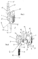
- FIG. 1 denotes a housing which, via a pair of bearing journals 2, one of which is shown in the drawing, to structural elements of an actuating member, for. B. a manual shift lever or on the input-side switching elements of a transmission can be fixed.
- the housing 1 has on its underside 3 two parallel and spaced apart extending bearing brackets 4, on whose respective outer sides bearing pins 5 are formed, one of which is shown and which define an axis 6 about which a .Betusch Inc.element 7 is pivotally mounted ,
- the mutually aligned holes 9 cooperate with the bearing pin 5 of the housing 1.
- the actuating element 7 is globally angularly configured and consists of one, adjoining the bearing cheeks 8 first part 7 'and one, perpendicular to the first part extending second part 7 ", at its, in the mounted state the housing 1 facing bottom a Verrastungskante 10.
- This latching edge 10 is designed and arranged for latching with a counter edge 11 integrally formed on the facing upper side of the housing 1.
- the second part 7 "of the actuating element 7 is set up with the proviso that an engagement between the Verrastungskante 10 and the opposite edge 11 under slight elastic deformation, thus shown without play. This engagement forms the locking position of the cable system as will be explained in more detail below.
- tension element 12 z. B. steel cable, whose, the housing facing the end of a profiled in the surface area, for example, toothed connecting portion 13 represents.
- the tension member 12 is integrated into a drawing, not shown, elastic enveloping body, on the other hand, it is arranged to be movable.
- the housing 1 has on its, the actuating element 7 facing side on a square in cross-section guide 14 which extends perpendicular to a longitudinal axis 15 of the tension member 12 and serves to receive a locking element 16.
- the latter is provided on its, the housing 1 facing side with an inner profile 17, which is intended for form-locking cooperation with the connecting portion 13 and set up.
- the locking element 16 is in the guide 14 with a spring element 18 in connection, through which the engagement between the Verrastungskante 10 and the opposite edge 11 is held under mechanical bias.
- This, the locking position of the cable system corresponding state is further characterized in that the not shown by a drawing, the underside 3 facing opening of the housing 1 in this inserted connecting portion 13 in this insertion position positively is secured by the inner profile 17 of the locking element. In this position, the tension element 12 is thus ready for operation.
- a movement of the locking element 16 between the in Fig. 1 shown locking position and a release position in which the engagement between the inner profile 17 and the connecting portion 13 is released, is thus effected by pivoting of the actuating element 7 about the axis 6. It can be seen that the movement of the locking element 16 is supported by the spring element 18 starting from the locking position into the release position. It can also be seen that a play-free engagement of the Vemegelungskante 10 with the opposite edge 11 is represented by the spring element 18 and is supported.
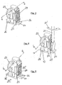
- cable system is in turn an actuating element 22 about an axis 6 on a housing 23 between an in Fig. 3 shown release position and a in Fig. 5 pivotally mounted shown locking position.
- the storage of the actuating element 22 on the housing 23 and the positive locking in the locking position are structurally in the same manner as in the embodiment according to the Fig. 1 and 2 educated. The same applies to the arrangement and guidance of a spring-loaded locking element 16. These design features are common to all embodiments. The latter also applies to the global angle-shaped, composed of two mutually perpendicular to each other, firmly together in connecting parts assembled structure of the actuator.
- a transfer to the locking position can be effected by the fact that in the enclosed by the bracket 24, still partially protruding from the slot recess 26, a screwdriver 21 or a structurally comparable tool used and rotated in the direction of arrow 21 ' is, whereby the actuating element 22 against the action of the spring element 18 (FIG. Fig. 2 ) is pivoted about the axis 6 until the locking state of the locking position is established by engagement of the Verrastungskante 10 with the opposite edge 11.
- This locking position is in Fig. 5 shown.
- the release position of the actuating element 22 be initiated by, in turn, by means of a screwdriver 21 or a structurally comparable tool, a force on the web element 26 'in the direction 21 "is exercised, thus in a, the engagement of the Verrastungskante 10 with the opposite edge 11 solving direction, where it an elastic deformation of the first and second parts 22 ', 22 "of the actuating element 22 comes.
- a subsequent pivotal movement takes place about the axis 6 into the in Fig. 3 shown release position under the action of the relaxing spring element 18th
- Fig. 7 shows the release position of the in the Fig. 1 and 2 shown cable system, which is shown with the cooperation of the spring element 18.
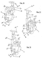
- the locking position is according to Fig. 8 is effected by means of a screwdriver 21 inserted into the slot 20 in that the screwdriver in the direction 21 '''is moved, so that a pivoting of the actuating element 7 about the axis 6 in the direction 6' results until it finally to an engagement of Verrastungskante 10 comes with the opposite edge 11 and the locking position is reached.
- Fig. 9 shows the locking position, which is characterized by the engagement of Verrastungskante 10 with the opposite edge 11.
- Fig. 10 shows that starting from the locking position, the release position can be achieved by a screwdriver 21 is now inserted into the slot 19 and on the walls of the slot, a force in the direction 21 '''' is applied.
- the actuating element 7 about the axis 6 in the direction of the arrow 6 "in the in Fig. 7 swung back shown release position.
- cable system is characterized by a housing 1 and an actuating element 27, which differs from the actuating element 7 in that now only one slot 20 is provided, which is intended and arranged for cooperation with a screwdriver 21 or a similar elongated tool.
- the slot 20 is located at the corner region of the two, the actuating element 27 representing, at a right angle to each other extending first and second parts 27 ', 27 ".
- the locking position is achieved by a screwdriver 21 is inserted into the slot 20 and the actuator 27 is pivoted by a force in the direction 21 "'about the axis 6 in the direction of arrow 6' in the locking position until it to an engagement of Verrastungskante 10 comes with the opposite edge 11.
- the Actuate 27 has a sufficient elasticity, so that with the exertion of forces in the directions 21 ''',21''''a sufficient, a release or causing the engagement of the Verrastungskante 10 and the opposite edge enabling deformation of the second Telles 27 "relative to the first part 27 'of the actuator 27 is reached.
Abstract
Description
Die Erfindung bezieht sich auf ein Übertragungssystem entsprechend dem Oberbegriff des Anspruchs 1.The invention relates to a transmission system according to the preamble of
Derartige Übertragungssysteme kommen beispielsweise in der Form von Seilzugsystemen in vielfältiger Form im Fahrzeugbau zum Einsatz, und zwar zur Übertragung von Schaltkräften zwischen einem Eingangsorgan, beispielsweise einem Handschalthebel oder einem Pedal einerseits und einer zu schaltenden Baugruppe, beispielsweise einem Wechselgetriebe oder auch einer Kupplung andererseits. Sie sind bekannt u. a in der Form der sogenannten Bowdenzüge und bestehen regelmäßig aus einem zur Kraftübertragung bestimmten, als Stahlseil ausgebildeten, in einem flexiblen Hüllkörper längsbeweglich angeordneten Zugelement, wobei die Enden des Hüllkörpers zur ortsfesten Anbringung an Teilen des Fahrzeugs bestimmt und eingerichtet sind.Such transmission systems are used for example in the form of cable systems in various forms in vehicle construction, namely for the transmission of switching forces between an input member, such as a manual shift lever or a pedal on the one hand and a circuit to be switched assembly, such as a change gear or a clutch on the other. They are known u. a in the form of the so-called Bowden cables and regularly consist of a specific for power transmission, designed as a steel cable, longitudinally movably arranged in a flexible Hüllkörper tension element, wherein the ends of the Hüllkörpers are intended for fixed attachment to parts of the vehicle and set up.
Aus der
Aus der
Ein von seinem Aufbau her und in seinen Eigenschaften im wesentlichen vergleichbares Übertragungssystem ist aus der
Das aus der
Bei der aus dem
Es ist die Aufgabe der Erfindung, ein Übertragungssystem der eingangs genannten Art mit Hinblick auf bequemeres Überführen zwischen einer Verriegelungsposition und einer Freigabeposition hin auszugestalten, so dass sich insgesamt die montagemäßige Handhabbarkeit verbessert. Gelöst ist diese Aufgabe bei einem solchen Übertragungssystem durch die Merkmale des Kennzeichnungsteils des Anspruchs 1.It is the object of the invention to design a transmission system of the type mentioned above with a view to more convenient transfer between a locking position and a release position, so that overall improves the assembly handling. This is solved Task in such a transmission system by the features of the characterizing part of
Ausgangspunkt ist ein global aus einem Gehäuse und einem an diesem zwischen der Freigabe- und der Verriegelungsposition schwenkbar angelenkten Betätigungselement bestehendes Kupplungsstück, in welchem das diesem zugekehrte Ende eines Zug- und/oder Druckelements lösbar aufgenommen ist. Das Kupplungsstück bildet das Bindeglied zu einer zu betätigenden Baugruppe einerseits und zu einem Betätigungsorgan andererseits und es werden die genannten Zug- oder Druckkräfte über dieses übertragen. Das Zug- und/oder Druckelement ist zu diesem Zweck in an sich bekannter Weise endseitig mit einem profilierten Verbindungsabschnitt versehen, der in der Verriegelungsposition mit entsprechend ausgebildeten Gegenelementen des Kupplungsstücks formschlüssig im Eingriff steht. Erfindungswesentlich ist, dass an dem Gehäuse und/oder dem Betätigungselement Betätigungsorgane angeordnet sind, die aus einer, der Längsachse des eingesetzten Zug- und/oder Druckelements entsprechenden oder einer zu dieser zumindest parallelen Richtung zugänglich und insbesondere betätigbar sind, um das Kupplungsstück zwischen den genannten Positionen schalten zu können. Letzteres kann in einfacher Weise mittels eines langgestreckten Werkzeugs geschehen, z.B. mit einem Schraubenzieher durchgeführt werden, und zwar in beiden Schaltrichtungen. Die Zugänglichkeit der Betätigungsorgane aus der genannten Richtung und zwar mit Blickrichtung auf das zugekehrte Ende des Zug- und/oder Druckelementes eröffnet eine auch unter räumlich eingeengten Verhältnissen bequeme Arbeitsmöglichkeit sowohl bei der Montage als auch bei der Demontage des Kupplungsstücks. Hinzutritt der weitere Vorteil, dass kein Spezialwerkzeug erforderlich ist, sondern von allgemein verfügbaren Standardwerkzeugen Gebrauch gemacht werden kann.The starting point is a globally consisting of a housing and a pivotally hinged to this between the release and the locking position actuator coupling element in which this facing the end of a tensile and / or pressure element is releasably received. The coupling piece forms the link to an assembly to be actuated on the one hand and to an actuating member on the other hand and said tensile or compressive forces are transmitted via this. The tension and / or pressure element is provided for this purpose in a conventional manner end with a profiled connecting portion which is positively engaged in the locking position with correspondingly formed counter-elements of the coupling piece. It is essential to the invention that on the housing and / or the actuating element actuators are arranged, which are accessible from a, the longitudinal axis of the applied tensile and / or pressure element corresponding or at least parallel to this direction and in particular actuated to the coupling piece between said To switch positions. The latter can be done easily by means of an elongate tool, e.g. be performed with a screwdriver, in both switching directions. The accessibility of the actuators from the direction mentioned and with a view towards the facing end of the tension and / or pressure element opens a convenient even under spatially constricted conditions work both during assembly and during disassembly of the coupling. Added to the further advantage that no special tools is required, but can be made of commonly available standard tools use.
Zweckmäßigerweise ist das Betätigungselement durch solche Mittel schwenkbar an dem Gehäuse angelenkt, die an dem freien Ende des einen der beiden, das Betätigungselement darstellenden Teile angeordnet sind. Die zur Verrastung des Betätigungselementes an dem Gehäuse in der Verriegelungsposition des Kupplungsstücks bestimmten Funktionselemente werden zweckmäßigerweise an dem freien Ende des anderen der beiden Teile angeordnet. Für die Darstellung einer Schaltbewegung der im Rahmen der genannten Elementenpaarung zusammenwirkenden Verrastungskante sowie der genannten Gegenkante steht somit ein größtmöglicher Weg zur Verfügung,Conveniently, the actuating element is articulated by such means pivotally mounted on the housing, which are arranged at the free end of one of the two, the actuating element performing parts. The latching of the actuating element to the housing in the locking position the coupling piece certain functional elements are advantageously arranged at the free end of the other of the two parts. For the representation of a switching movement of cooperating within the framework of said element pairing Verrastungskante and said counter edge is thus the greatest possible way,
Das Kupplungsstück ist mit der Maßgabe ausgebildet, dass die Überführung ausgehend von der Freigabeposition in Richtung auf die Verriegelungsposition hin entgegen der Rückstellkraft eines Federelements erfolgt, durch welches somit die Bewegung der Rücküberführung in die Freigabeposition zumindest unterstützt wird.The coupling piece is designed with the proviso that the transfer takes place starting from the release position in the direction of the locking position against the restoring force of a spring element, by which thus the movement of the return transfer is at least supported in the release position.
Die Verriegelungsposition ist formschlüssig nach Art einer Verrastung gesichert, welche entsprechend den Merkmalen des Anspruchs 2 durch eine elastische Vorspannung gekennzeichnet und somit spielfrei ist. Technisch dargestellt werden kann die genannte Elementenpaarung durch eine Verriegelungskante an dem einen Teil und eine mit dieser zusammenwirkende Gegenkante an dem anderen Teil. Die Komponenten des Kupplungsstücks sind vorzugsweise aus Kunststoff ausgebildet, so dass eine erforderliche Elastizität einfach bereitstellbar ist.The locking position is positively secured in the manner of a latch, which is characterized according to the features of
Die Merkmale des Anspruchs 3 sind auf eine erste konstruktive Konkretisierung der eingangs genannten Betätigungsorgane gerichtet. Die Hohlräume sind an diese Zweckbestimmung angepasst und können ferner im Umfangsbereich profiliert, insbesondere an ein bestimmtes Werkzeug wie z. B. einen Schraubenzieher angepasst sein.The features of
Die Merkmale der Ansprüche 4 und 5 sind auf eine andere konstruktive Konkretisierung der genannten Betätigungsorgane gerichtet, welche sich von der vorstehend zitierten Form im wesentlichen nur darin unterscheidet, dass anstelle von zwei Hohlräumen nunmehr nur ein Hohlraum vorgesehen ist, der zur Aufnahme eines Werkzeugs bestimmt ist.The features of
Zusätzlich zu der ihrem Bestimmungszweck entsprechenden Bemessung des Hohlraumes ist mit Hinblick auf eine bequeme, insbesondere leichtgängige Durchführung der Schaltbewegungen des Betätigungselementes entsprechend den Merkmalen des Anspruchs 6 vorgesehen, dass das Teil, von dem aus sich der Hohlraum / die Hohlräume erstrecken, eine hinreichende Elastizität aufweist. Dies kann eine entsprechende Werkstoffwahl oder durch dementsprechende Gestaltung dieses Teiles erreicht werden.In addition to the design of the cavity corresponding to its intended purpose, it is provided with regard to a convenient, in particular smooth implementation of the switching movements of the actuating element according to the features of
Die Merkmale der Ansprüche 7 bis 9 sind auf eine weitere konstruktive Konkretisierung der genannten Betätigungsorgane gerichtet. Diese sind hiernach durch einen Bügel und ein Stegelement dargestellt, welche in Verbindung mit einem Werkzeug zur Einleitung der Schaltbewegungen des Kupplungsstücks bestimmt sind. Der Bügel kann im Umfangsbereich profiliert und an die Gestalt des einzusetzenden Werkzeugs angepasst sein. Das Stegelement ist demgegenüber nur zur Ausübung einer normal zu dessen Oberfläche bestimmten Kraft eingerichtet, welche darauf abzielt, den Verrastungseingriff in der Verriegelungsposition zu lösen. Dementsprechend befindet sich die genannte Elementenpaarung in unmittelbarer Nähe des Stegelements.The features of
Die Merkmale des Anspruchs 10 sind auf eine vorteilhafte konstruktive Ausbildung der Lagerung des Betätigungselements an dem Gehäuse gerichtet.The features of
Gemeinsam ist allen Ausbildungsformen des Kupplungsstücks, dass die zur Durchführung der vorstehend beschriebenen Schaltbewegungen benötigten Betätigungsorgane sämtlich aus einer Richtung zumindest parallel zu der Längsachse des eingesetzten Zug- und/oder Druckelements zugänglich sind und dass kein Spezialwerkzeug benötigt wird.Common to all embodiments of the coupling piece that the actuators required to carry out the switching operations described above are all accessible from one direction at least parallel to the longitudinal axis of the applied tensile and / or pressure element and that no special tool is needed.
Die Erfindung wird im Folgenden unter Bezugnahme auf die in den Zeichnungen schematisch wiedergegebenen Ausführungsbeispiele näher erläutert werden. Es zeigen:
-
Fig. 1 eine perspektivische Darstellung eines ersten Ausführungsbeispiels des Endbereichs eines erfindungsgemäßen Übertragungssystems in der Verriegelungsposition; -
Fig. 2 das Ausführungsbeispiel gemäßFig. 1 in einer Explosionsdarstellung; -
Fig. 3 eine perspektivische Darstellung eines zweiten Ausführungsbeispiels des Endbereiches eines Übertragungssystems in der Freigabeposition; -
Fig. 4 eine perspektivische, die Überführung in die Verriegelungsposition ausgehend von der Freigabeposition zeigende Darstellung des Ausführungsbeispiels gemäßFig. 3 ; -
Fig. 5 eine perspektivische Darstellung des Ausführungsbeispiels gemäßFig. 3 in der Verriegelungsposition; -
Fig. 6 eine perspektivische, die Überführung in die Freigabeposition ausgehend von der Verriegelungsposition zeigende Darstellung des Ausführungsbeispiels gemäßFig. 3 ; -
Fig. 7 eine perspektivische Darstellung des inFig. 1 gezeigten Ausführungsbeispiels in der Freigabeposition; -
Fig. 8 eine perspektivische, die Überführung in die Verriegelungsposition ausgehend von der Freigabeposition zeigende Darstellung des Ausführungsbeispiels gemäßFig. 7 ; -
Fig. 9 eine perspektivische Darstellung des inFig. 1 gezeigten Ausführungsbeispiels in der Freigabeposition: -
Fig. 10 eine perspektivische, die Überführung-in die Freigabeposition ausgehend von der Verriegelungsposition zeigende Darstellung des Ausführungsbeispiels gemäßFig. 1 ; -
Fig. 11 eine perspektivische, die Überführung eines dritten Ausführungsbeispiels in die Verriegelungsposition ausgehend von der Freigabeposition zeigende Darstellung; -
Fig. 12 eine perspektivische, die Überführung des Ausführungsbeispiels gemäßFig. 11 in die Freigabeposition ausgehend von der Verriegelungsposition zeigende Darstellung.
-
Fig. 1 a perspective view of a first embodiment of the end portion of a transmission system according to the invention in the locking position; -
Fig. 2 the embodiment according toFig. 1 in an exploded view; -
Fig. 3 a perspective view of a second embodiment of the end portion of a transmission system in the release position; -
Fig. 4 a perspective, the transfer into the locking position, starting from the release position facing representation of the embodiment according toFig. 3 ; -
Fig. 5 a perspective view of the embodiment according toFig. 3 in the locking position; -
Fig. 6 a perspective, the transfer to the release position starting from the locking position facing representation of the embodiment according toFig. 3 ; -
Fig. 7 a perspective view of the inFig. 1 shown embodiment in the release position; -
Fig. 8 a perspective, the transfer into the locking position, starting from the release position facing representation of the embodiment according toFig. 7 ; -
Fig. 9 a perspective view of the inFig. 1 shown embodiment in the release position: -
Fig. 10 a perspective, the transfer-in the release position starting from the locking position facing representation of the embodiment according toFig. 1 ; -
Fig. 11 a perspective, the transfer of a third embodiment in the locking position starting from the release position showing representation; -
Fig. 12 a perspective, the transfer of the embodiment according toFig. 11 in the release position starting from the locking position showing view.
Mit 1 ist in den
An dem Betätigungselement 7, und zwar dessen der Unterseite 3 zugekehrten Ende sind zwei zueinander parallele Lagerwangen 8 angeformt, deren zueinander fluchtende Bohrungen 9 mit den Lagerzapfen 5 des Gehäuses 1 zusammenwirken.On the
Das Betätigungselement 7 ist global winkelartig ausgestaltet und besteht aus einem, sich an die Lagerwangen 8 anschließenden ersten Teil 7' und einem, sich senkrecht zu den ersten Teil erstreckenden zweiten Teil 7", an dessen, im montierten Zustand dem Gehäuse 1 zugekehrter Unterseite eine Verrastungskante 10 angeformt ist. Diese Verrastungskante 10 ist zum Verrasten mit einer an der zugekehrten Oberseite des Gehäuses 1 angeformten Gegenkante 11 bestimmt und eingerichtet.The
Das zweite Teil 7" des Betätigungselementes 7 ist mit der Maßgabe eingerichtet, dass ein Eingriff zwischen der Verrastungskante 10 und der Gegenkante 11 unter geringfügiger elastischer Verformung, somit spielfrei dargestellt ist. Dieser Eingriff bildet die Verriegelungsposition des Seilzugsystems wie im Folgenden noch näher erläutert werden wird.The
Mit 12 ein Zugelement, z. B. Stahlseil bezeichnet, dessen, dem Gehäuse zugekehrtes Ende einen im Oberflächenbereich profilierten, beispielsweise verzahnten Verbindungsabschnitt 13 darstellt. Das Zugelement 12 ist in einen zeichnerisch nicht dargestellten, elastischen Hüllkörper eingebunden, demgegenüber es beweglich angeordnet ist.With 12 a tension element, z. B. steel cable, whose, the housing facing the end of a profiled in the surface area, for example, toothed connecting
Die nachfolgende Beschreibung ist lediglich beispielhaft auf ein Seilzugsystem, nämlich eine seilartige, zur Übertragung von Zugkräften gerichtete Konkretisierung des Zug- und/oder Druckelementes gerichtet. Es versteht sich jedoch, dass diese erfindungsgemäße Technik gleichermaßen bei zur Übertragung von Druckkräften eingerichteten Druckelementen oder bei sowohl zur Übertragung von Druck- als auch von Zugkräften eingerichteten Zug- und Druckelementen vorteilhaft eingesetzt werden kann.The following description is merely exemplary of a cable system, namely directed a rope-like, directed to the transmission of tensile forces concretization of the tensile and / or pressure element. It is understood, however, that this technique according to the invention can equally be used advantageously in the case of printing elements adapted for the transmission of compressive forces or in the case of tension and compression elements set up both for the transmission of compressive and tensile forces.
Das Gehäuse 1 weist auf seiner, dem Betätigungselement 7 zugekehrten Seite eine im Querschnitt quadratische Führung 14 auf, die sich senkrecht zu einer Längsachse 15 des Zugelementes 12 erstreckt und zur Aufnahme eines Verriegelungselementes 16 dient. Letzteres ist auf seiner, dem Gehäuse 1 zugekehrten Seite mit einem Innenprofil 17 versehen, welches zum formschlüssigen Zusammenwirken mit dem Verbindungsabschnitt 13 bestimmt und eingerichtet ist.The
Das Verriegelungselement 16 steht in der Führung 14 mit einem Federelement 18 in Verbindung, durch welches der Eingriff zwischen der Verrastungskante 10 und der Gegenkante 11 unter mechanischer Vorspannung gehalten ist. Dieser, der Verriegelungsposition des Seilzugsystems entsprechende Zustand ist ferner dadurch gekennzeichnet, dass der durch eine zeichnerisch nicht dargestellte, der Unterseite 3 zugekehrte Öffnung des Gehäuses 1 hindurch in dieses eingeführte Verbindungsabschnitt 13 in dieser Einsetzposition formschlüssig durch das Innenprofil 17 des Verriegelungselementes gesichert ist. In dieser Position ist das Zugelement 12 somit betriebsbereit.The locking
Eine Bewegung des Verriegelungselementes 16 zwischen der in
Mit 19, 20 sind zwei entlang des zweiten Teiles 7" des Betätigungselementes 7 voneinander beabstandete, sich parallel zu der Achse 15 erstreckende Schlitze bezeichnet, die in Verbindung mit einem angedeuteten Schraubenzieher 21 oder einem vergleichbaren Werkzeug zum Überführen des Betätigungselementes 7 von der Freigabe- in die Verriegelungsposition und umgekehrt bestimmt sind. Man erkennt, dass aufgrund der Orientierung der Längserstreckung der diese Schlitze 19, 20 definierenden Ausnehmungen ein zur Überführung des Verriegelungselementes16 zwischen der Freigabeposition und der Verriegelungsposition zu benutzendes Werkzeug stets in der Richtung der Längsachse 15 des Zugelementes 12 oder einer zu dieser parallelen Achse 15' einzusetzen ist.19, 20 are two along the
Die Benutzung des in den
Bei dem in den
Die Lagerung des Betätigungselements 22 an dem Gehäuse 23 sowie dessen formschlüssige Verrastung in der Verriegelungsposition sind konstruktiv in gleicher Weise wie bei dem Ausführungsbeispiel gemäß den
Mit 24 ist ein an dem Gehäuse 23 angeformter, sich durch einen Schlitz 25 eines ersten Teiles 22' des Betätigungselementes 22 hindurcherstreckender Bügel bezeichnet, der in der Freigabeposition des Betätigungselementes 22 nur noch teilweise aus dem genannten Schlitz herausragt. Wie
Mit 26' ist ein Stegelement bezeichnet, welches im Bereich der Verrastungskante 10 an einem zweiten Teil 22" des Betätigungselementes 22 angeformt ist und sich in der Verriegelungsposition über das Gehäuse 23 hinauserstreckt. Das Stegelement 26' bildet zumindest in der Verrastungsposition eine Fläche, die sich senkrecht zu der Längsrichtung eines innerhalb des Gehäuses 23 aufzunehmenden Zugelementes 12 (
Man erkennt, dass zum Bewegen des Betätigungselementes 22 ein Werkzeug benutzt wird, welches ausschließlich in einer der Längsrichtung des Zugelements 12 (
Das in den
Ausgehend von der in
Umgekehrt wird ausgehend von der in
Wesentlich für die in den
Gemeinsam ist allen der vorstehend beschriebenen Ausführungsformen, dass ein Werkzeug stets im wesentlichen in der Längsrichtung oder auch parallel zu der Längsrichtung eines Zugelementes zum Einsatz kommt. Dies stellt in vielen Fällen eine bevorzugte Richtung dar, welche eine montagemäßig bequeme Handhabung dieses Seilzugsystems ermöglicht, insbesondere unter schwierigen, räumlich engen Einbauverhältnissen.It is common to all of the embodiments described above that a tool is always used essentially in the longitudinal direction or also parallel to the longitudinal direction of a tension element. This is in many cases a preferred direction, which allows a montagemäßig comfortable handling of this cable system, especially under difficult, spatially tight installation conditions.
Claims (10)
Applications Claiming Priority (1)
| Application Number | Priority Date | Filing Date | Title |
|---|---|---|---|
| DE200710035641 DE102007035641B3 (en) | 2007-07-27 | 2007-07-27 | transmission system |
Publications (3)
| Publication Number | Publication Date |
|---|---|
| EP2019216A2 true EP2019216A2 (en) | 2009-01-28 |
| EP2019216A3 EP2019216A3 (en) | 2011-05-04 |
| EP2019216B1 EP2019216B1 (en) | 2014-09-03 |
Family
ID=39884603
Family Applications (1)
| Application Number | Title | Priority Date | Filing Date |
|---|---|---|---|
| EP20080013234 Expired - Fee Related EP2019216B1 (en) | 2007-07-27 | 2008-07-23 | Transfer system |
Country Status (2)
| Country | Link |
|---|---|
| EP (1) | EP2019216B1 (en) |
| DE (1) | DE102007035641B3 (en) |
Cited By (2)
| Publication number | Priority date | Publication date | Assignee | Title |
|---|---|---|---|---|
| US20140169860A1 (en) * | 2011-04-29 | 2014-06-19 | Dura Automotive Systems Sas | Device for locking a body onto a rod |
| US8850920B2 (en) | 2008-10-10 | 2014-10-07 | Kongsberg Driveline Systems I, Inc. | Adjustment device for a remote control assembly having an easily engageable and disengageable locking element |
Families Citing this family (2)
| Publication number | Priority date | Publication date | Assignee | Title |
|---|---|---|---|---|
| DE202014101784U1 (en) * | 2014-04-15 | 2015-07-20 | Al-Ko Kober Ges. M.B.H | cable setting |
| DE102016007487A1 (en) * | 2016-06-18 | 2017-12-21 | GM Global Technology Operations LLC (n. d. Gesetzen des Staates Delaware) | Method for producing a motor vehicle |
Citations (4)
| Publication number | Priority date | Publication date | Assignee | Title |
|---|---|---|---|---|
| DE19730683A1 (en) | 1996-08-22 | 1998-02-26 | Vorbrueggen Vofa Werk | Actuating link for operating devices, esp. in car |
| DE29817887U1 (en) | 1998-10-07 | 1999-01-07 | Opel Adam Ag | Device for the length-adjustable fastening of the cable of an actuating cable |
| DE10127630A1 (en) | 2000-06-13 | 2002-02-21 | Kuester Automotive Control Sys | Length adjustment device, especially remote actuator in vehicle, has hollow element held in first axial position by spring bias force or in second axial position against spring bias force |
| DE102005028634A1 (en) | 2004-06-25 | 2006-01-26 | Dura Automotive Systems Gmbh | Pre-stressed spring packet, has base unit attached at retaining unit in such manner that it holds spring under pre-stressing, where base unit is manufactured from plastic material, and hook unit provided with lug at base unit |
Family Cites Families (2)
| Publication number | Priority date | Publication date | Assignee | Title |
|---|---|---|---|---|
| DE8225387U1 (en) * | 1982-09-09 | 1984-09-06 | Fichtel & Sachs Ag, 8720 Schweinfurt | CONNECTING DEVICE FOR AN OPERATING CABLE |
| DE9304462U1 (en) * | 1993-03-24 | 1993-05-19 | Vofa-Werk Xavier Vorbrueggen Gmbh & Co Kg, 4000 Duesseldorf, De |
-
2007
- 2007-07-27 DE DE200710035641 patent/DE102007035641B3/en not_active Expired - Fee Related
-
2008
- 2008-07-23 EP EP20080013234 patent/EP2019216B1/en not_active Expired - Fee Related
Patent Citations (4)
| Publication number | Priority date | Publication date | Assignee | Title |
|---|---|---|---|---|
| DE19730683A1 (en) | 1996-08-22 | 1998-02-26 | Vorbrueggen Vofa Werk | Actuating link for operating devices, esp. in car |
| DE29817887U1 (en) | 1998-10-07 | 1999-01-07 | Opel Adam Ag | Device for the length-adjustable fastening of the cable of an actuating cable |
| DE10127630A1 (en) | 2000-06-13 | 2002-02-21 | Kuester Automotive Control Sys | Length adjustment device, especially remote actuator in vehicle, has hollow element held in first axial position by spring bias force or in second axial position against spring bias force |
| DE102005028634A1 (en) | 2004-06-25 | 2006-01-26 | Dura Automotive Systems Gmbh | Pre-stressed spring packet, has base unit attached at retaining unit in such manner that it holds spring under pre-stressing, where base unit is manufactured from plastic material, and hook unit provided with lug at base unit |
Cited By (2)
| Publication number | Priority date | Publication date | Assignee | Title |
|---|---|---|---|---|
| US8850920B2 (en) | 2008-10-10 | 2014-10-07 | Kongsberg Driveline Systems I, Inc. | Adjustment device for a remote control assembly having an easily engageable and disengageable locking element |
| US20140169860A1 (en) * | 2011-04-29 | 2014-06-19 | Dura Automotive Systems Sas | Device for locking a body onto a rod |
Also Published As
| Publication number | Publication date |
|---|---|
| DE102007035641B3 (en) | 2009-02-19 |
| EP2019216B1 (en) | 2014-09-03 |
| EP2019216A3 (en) | 2011-05-04 |
Similar Documents
| Publication | Publication Date | Title |
|---|---|---|
| DE102009043933B4 (en) | An automobile door handle | |
| DE102006046908A1 (en) | Wiper blade locking device | |
| DE202015106673U1 (en) | Bayable component | |
| DE102017107943B3 (en) | Locking mechanism for releasably locking a first component to a second component and thus formed arrangement | |
| DE19918911A1 (en) | Fastener | |
| DE102008059827B4 (en) | Sliding shoe for a switching element of a switching device and switching element with such a sliding shoe | |
| EP2019216B1 (en) | Transfer system | |
| DE19730683B4 (en) | Control cable for the operation of equipment, especially in vehicles | |
| WO2015124399A1 (en) | Actuation device for a parking brake | |
| EP2033266B1 (en) | Cable connection clamp | |
| DE10012382B4 (en) | Manual shift lever for a vehicle change gearbox | |
| DE202005008178U1 (en) | Gear switch unit for vehicle, comprising locking element for reverse gear attached to base at gear switch lever | |
| EP1628046B1 (en) | Shifting device for a vehicle transmission | |
| WO2009000390A1 (en) | Connecting device | |
| DE102014103752B3 (en) | buckle tongue | |
| DE102004009331B4 (en) | Operating mechanism for Bowden cables | |
| EP1413398B1 (en) | Rapid securing device with locking device | |
| EP3623561B1 (en) | Driving carriage for a gate as well as a gate drive | |
| EP1818230B1 (en) | Handbrake device | |
| AT523271B1 (en) | Guide arrangement for guiding at least one movable furniture part | |
| DE202008011190U1 (en) | Hinge and tool for disassembling a linear damper from a hinge | |
| DE102007018731A1 (en) | Switching and selecting device for vehicle, has locking element formed corresponding to locking grooves in switching lever-sided locking surface, and longitudinally-swivelably supported at switching lever | |
| DE102007028964B4 (en) | Assembly of a vehicle transmission with a locking pin for locking a transmission part of the assembly | |
| DE19840642A1 (en) | Two-part holding fitting for automotive control run for cable or pushrod consists essentially of two U-shaped parts, one part attached to vehicle bodywork leaving the U-shaped open to receive control run | |
| EP2347843B1 (en) | Lock device for locking a depth stop rod, additional handle and handheld machine tool |
Legal Events
| Date | Code | Title | Description |
|---|---|---|---|
| PUAI | Public reference made under article 153(3) epc to a published international application that has entered the european phase |
Free format text: ORIGINAL CODE: 0009012 |
|
| AK | Designated contracting states |
Kind code of ref document: A2 Designated state(s): AT BE BG CH CY CZ DE DK EE ES FI FR GB GR HR HU IE IS IT LI LT LU LV MC MT NL NO PL PT RO SE SI SK TR |
|
| AX | Request for extension of the european patent |
Extension state: AL BA MK RS |
|
| PUAL | Search report despatched |
Free format text: ORIGINAL CODE: 0009013 |
|
| AK | Designated contracting states |
Kind code of ref document: A3 Designated state(s): AT BE BG CH CY CZ DE DK EE ES FI FR GB GR HR HU IE IS IT LI LT LU LV MC MT NL NO PL PT RO SE SI SK TR |
|
| AX | Request for extension of the european patent |
Extension state: AL BA MK RS |
|
| 17P | Request for examination filed |
Effective date: 20110909 |
|
| AKX | Designation fees paid |
Designated state(s): CZ DE FR IT |
|
| GRAP | Despatch of communication of intention to grant a patent |
Free format text: ORIGINAL CODE: EPIDOSNIGR1 |
|
| INTG | Intention to grant announced |
Effective date: 20140313 |
|
| GRAS | Grant fee paid |
Free format text: ORIGINAL CODE: EPIDOSNIGR3 |
|
| GRAA | (expected) grant |
Free format text: ORIGINAL CODE: 0009210 |
|
| AK | Designated contracting states |
Kind code of ref document: B1 Designated state(s): CZ DE FR IT |
|
| REG | Reference to a national code |
Ref country code: DE Ref legal event code: R096 Ref document number: 502008012161 Country of ref document: DE Effective date: 20141016 |
|
| PG25 | Lapsed in a contracting state [announced via postgrant information from national office to epo] |
Ref country code: CZ Free format text: LAPSE BECAUSE OF FAILURE TO SUBMIT A TRANSLATION OF THE DESCRIPTION OR TO PAY THE FEE WITHIN THE PRESCRIBED TIME-LIMIT Effective date: 20140903 |
|
| REG | Reference to a national code |
Ref country code: DE Ref legal event code: R097 Ref document number: 502008012161 Country of ref document: DE |
|
| PLBE | No opposition filed within time limit |
Free format text: ORIGINAL CODE: 0009261 |
|
| STAA | Information on the status of an ep patent application or granted ep patent |
Free format text: STATUS: NO OPPOSITION FILED WITHIN TIME LIMIT |
|
| REG | Reference to a national code |
Ref country code: FR Ref legal event code: PLFP Year of fee payment: 8 |
|
| 26N | No opposition filed |
Effective date: 20150604 |
|
| PG25 | Lapsed in a contracting state [announced via postgrant information from national office to epo] |
Ref country code: IT Free format text: LAPSE BECAUSE OF FAILURE TO SUBMIT A TRANSLATION OF THE DESCRIPTION OR TO PAY THE FEE WITHIN THE PRESCRIBED TIME-LIMIT Effective date: 20140903 |
|
| PGFP | Annual fee paid to national office [announced via postgrant information from national office to epo] |
Ref country code: DE Payment date: 20150729 Year of fee payment: 8 |
|
| PGFP | Annual fee paid to national office [announced via postgrant information from national office to epo] |
Ref country code: FR Payment date: 20150717 Year of fee payment: 8 |
|
| REG | Reference to a national code |
Ref country code: DE Ref legal event code: R119 Ref document number: 502008012161 Country of ref document: DE |
|
| PG25 | Lapsed in a contracting state [announced via postgrant information from national office to epo] |
Ref country code: FR Free format text: LAPSE BECAUSE OF NON-PAYMENT OF DUE FEES Effective date: 20160801 Ref country code: DE Free format text: LAPSE BECAUSE OF NON-PAYMENT OF DUE FEES Effective date: 20170201 |
|
| REG | Reference to a national code |
Ref country code: FR Ref legal event code: ST Effective date: 20170331 |