EP2019211B1 - Clamping device - Google Patents
Clamping device Download PDFInfo
- Publication number
- EP2019211B1 EP2019211B1 EP20080160970 EP08160970A EP2019211B1 EP 2019211 B1 EP2019211 B1 EP 2019211B1 EP 20080160970 EP20080160970 EP 20080160970 EP 08160970 A EP08160970 A EP 08160970A EP 2019211 B1 EP2019211 B1 EP 2019211B1
- Authority
- EP
- European Patent Office
- Prior art keywords
- further object
- engagement
- clamping device
- wire
- engagement part
- Prior art date
- Legal status (The legal status is an assumption and is not a legal conclusion. Google has not performed a legal analysis and makes no representation as to the accuracy of the status listed.)
- Active
Links
Images


Classifications
-
- F—MECHANICAL ENGINEERING; LIGHTING; HEATING; WEAPONS; BLASTING
- F16—ENGINEERING ELEMENTS AND UNITS; GENERAL MEASURES FOR PRODUCING AND MAINTAINING EFFECTIVE FUNCTIONING OF MACHINES OR INSTALLATIONS; THERMAL INSULATION IN GENERAL
- F16B—DEVICES FOR FASTENING OR SECURING CONSTRUCTIONAL ELEMENTS OR MACHINE PARTS TOGETHER, e.g. NAILS, BOLTS, CIRCLIPS, CLAMPS, CLIPS OR WEDGES; JOINTS OR JOINTING
- F16B2/00—Friction-grip releasable fastenings
- F16B2/20—Clips, i.e. with gripping action effected solely by the inherent resistance to deformation of the material of the fastening
- F16B2/22—Clips, i.e. with gripping action effected solely by the inherent resistance to deformation of the material of the fastening of resilient material, e.g. rubbery material
- F16B2/24—Clips, i.e. with gripping action effected solely by the inherent resistance to deformation of the material of the fastening of resilient material, e.g. rubbery material of metal
- F16B2/248—Clips, i.e. with gripping action effected solely by the inherent resistance to deformation of the material of the fastening of resilient material, e.g. rubbery material of metal of wire
-
- F—MECHANICAL ENGINEERING; LIGHTING; HEATING; WEAPONS; BLASTING
- F16—ENGINEERING ELEMENTS AND UNITS; GENERAL MEASURES FOR PRODUCING AND MAINTAINING EFFECTIVE FUNCTIONING OF MACHINES OR INSTALLATIONS; THERMAL INSULATION IN GENERAL
- F16B—DEVICES FOR FASTENING OR SECURING CONSTRUCTIONAL ELEMENTS OR MACHINE PARTS TOGETHER, e.g. NAILS, BOLTS, CIRCLIPS, CLAMPS, CLIPS OR WEDGES; JOINTS OR JOINTING
- F16B2/00—Friction-grip releasable fastenings
- F16B2/20—Clips, i.e. with gripping action effected solely by the inherent resistance to deformation of the material of the fastening
- F16B2/22—Clips, i.e. with gripping action effected solely by the inherent resistance to deformation of the material of the fastening of resilient material, e.g. rubbery material
- F16B2/24—Clips, i.e. with gripping action effected solely by the inherent resistance to deformation of the material of the fastening of resilient material, e.g. rubbery material of metal
- F16B2/241—Clips, i.e. with gripping action effected solely by the inherent resistance to deformation of the material of the fastening of resilient material, e.g. rubbery material of metal of sheet metal
- F16B2/245—Clips, i.e. with gripping action effected solely by the inherent resistance to deformation of the material of the fastening of resilient material, e.g. rubbery material of metal of sheet metal external, i.e. with contracting action
- F16B2/246—Clips, i.e. with gripping action effected solely by the inherent resistance to deformation of the material of the fastening of resilient material, e.g. rubbery material of metal of sheet metal external, i.e. with contracting action the clip being released by tilting the clip or a part thereof to a position in which the axis of the openings surrounding the gripped elements is parallel to, or coincides with, the axis of the gripped elements
Definitions
- the present invention relates to a clamping device which can, for example, be used for attaching an object to a further object.
- the term further object is to be understood as referring to any object such as a support. Examples which may be mentioned include a wire, rod, plate or tube which may be round, polygonal and the like. However, the term is also understood to include a profiled edge or another part.
- clamping devices In many cases, large numbers of clamping devices have to be used in order to attach various kinds of objects. This is the case, for example, in horticulture where lines and other structures have to be supported at regular intervals over great distances. Other applications are the installation and assembly industry, the consumer market and industrial products. In these cases, it is important that such clamping devices, on the one hand, can readily be fitted and, on the other hand, provide sufficient clamping force. In addition, it is important that such clamping devices can be produced relatively inexpensively and can be disposed of in future without having any adverse impact on the environment.
- the clamping device has to be able to allow for any irregularities of the wire or rod without problem.
- US-A-3,883,934 discloses a clamping device comprising a first post engagement part and a second post engagement part. Each engagement part is formed by one or more turns which accommodate the post between them.
- FR 2,835,575 discloses a clamping device in which a wall is placed on a panel. This panel is engaged by two parts which have been bent at right angles.
- US 2003/0227115 discloses a clamping device having two further object engagement parts, wherein each part comprises a loop shaped wire having a smaller loop at the centre thereof.
- US 2 344 816 discloses a clamping device having two loop shaped further object engagement parts, wherein each loop is wound like a spiral.
- FR 2 712 907 discloses a clamping device having two spaced further object engagement parts each provided with an eyelet in which a rod is received.
- US 4 893 788 discloses a similar method for clamping as disclosed in FR 2 712 907 .
- the clamping device in an inexpensive manner by manufacturing it from a single wire part. Due to the resilient nature, small variations in the dimensions of the wire, rod or other support can be allowed for in a simple manner. Any desired object can be attached to the clamping device at any desired location in any desired manner.
- the engagement members are arranged at a distance from one another which is greater than the thickness/width of the respective further object such as a wire, rod and the like. As a result thereof, e.g. the rod can be accommodated between these two engagement members if the plane through the engagement members is placed at right angles to the plane of a rod. This can be achieved by the user by pinching the first further object engagement part and the second engagement part together.
- the engagement members preferably comprise one or two engagement eyelets.
- Such engagement eyelets may have any conceivable shape, such as triangular, hook-shaped, rectangular, elliptical, etc. According to an advantageous embodiment, these are of an approximately circular and, more particularly, comprise at least one wire turn or revolution. In particular in the case of a circular embodiment and when a wire turn is present, it is in some cases possible to achieve additional clamping of the further object, as the latter is pushed inside, due to the rounding of two opposite engagement eyelets, into the space between the rounding and the connecting part between the two eyelets.
- the eyelets it is also possible for the eyelets to be solid and to shape them in any conceivable way.
- the first and second engagement part may be identical, in which case these will obviously extend at different angles in the unloaded state. It is also possible for one of the further object engagement parts to be embodied differently, for example in the shape of a hook.
- the resilient connection between the first and second further object engagement parts may be realised as a function of the desired resilience, the desired length of the various components and the thickness of the wire used. This means that if a relatively stiff wire is used to produce the clamping device and the lever arm for moving the two further object engagement parts towards one another is relatively small, it is preferable if the resilient connection is designed as a turn or turns. If the lever is relatively large or the wire thickness is relatively small, a simple wire connection is sufficient.
- the choice of material for the wire will depend on the intended use and includes plastic, ferrous and non-ferrous injection-moulding products.
- the above-described rod for example by providing it with threaded ends. It is possible to place the clamping device according to the invention on such a wire end in any desired position and subsequently, by rotation of the securing device and wire ends with respect to one another, ensure accurate positioning of these two parts with respect to one another. In addition, it is thus possible to achieve a very precise adjustment, depending on the pitch of the screw thread on the wire end.
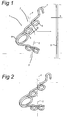
- a clamping device is denoted overall by reference numeral 1. It is embodied for clamping engagement with a rod 9.
- the clamping device 1 comprises a first further object engagement part 2 and a second further object engagement part 3.
- Each further object engagement part comprises two adjacent, approximately circular engagement eyelets 6.
- the engagement eyelets 6 are a distance apart and the axis extending in between is denoted by reference numerals 4 and 5, respectively.
- a resilient connection 8 is provided between the first and second engagement part 2, 3. With the present invention, this resilient connection 8 is formed by a turn.
- a securing hook is denoted by reference numeral 7. It will be understood that the latter can be arranged in any desired location and serves for attaching any kind of object thereto.
- the wire or rod 9 has a width b. Width b is smaller than distance a.
- Fig. 2 shows the state of the clamping device 1 when it is pinched by a human hand.
- the latter is preferably pinched until the lines 4 and 5 are in line with one another.
- any object having a width smaller than a, such as having a width b, can be accommodated.
- Fig. 3 which shows the situation after the first and second further object engagement parts have been released. Due to the resilient connection 8, these will then rebound until the "fictitious" distance between two engagement eyelets 6 which belong together corresponds to distance b.
- the lines 4 and 5 extend at an angle which differs from the angle in the inoperative position as illustrated in Fig. 1 , so that there is sufficient tolerance in the clamping device to allow for dimensional inaccuracies and subsequent alterations.
- first further object engagement part 2 and second further object engagement part 3 By clamping the first further object engagement part 2 and second further object engagement part 3 in opposite directions, no displacement along the rod 9 is possible in any direction. If the object to be clamped has relatively small dimensions with respect to the radius of curvature of the engagement eyelets 6, the object is pressed down further into the spaces 10 when it is clamped in ( Fig. 3 ). In this case, the object is not only clamped in, but also locked in, in the plane at right angles to the plane of the drawing in Fig. 1 . This locking action means that the first and second further object engagement parts have to be moved towards one another over a small distance in order to enable the wire or rod or the like to be released. In this case, removal by sliding is not possible.
- Fig. 4 shows a second embodiment of the present invention which is denoted overall by reference numeral 21. It also comprises first and second further object engagement parts 22, 23.
- the first further object engagement part comprises two eyelets, while the second further object engagement part 23 comprises a hook.
- the resilient connecting part 28 in this embodiment is slightly longer/less stiff than in the first embodiment, so that it is no longer necessary to provide an additional complete wire turn.
- Reference numeral 27 denotes a suspension hook. This structure also produces a clamping force in two directions, as a result of which sliding along the rod or wire 29 is effectively prevented.
- Fig. 5 shows a further variant of the invention.
- the rod is denoted by reference numeral 19 and comprises a wire end.
- the clamping device is embodied in accordance with the embodiment from Figs. 1-3 and is denoted overall by reference numeral 21.
- the clamping device 21 can be positioned on rod 19 at any desired position. Rotating rod 19 with respect to the clamping device 21 will result in a mutual displacement on account of rod 19 being threaded. This means that part 21 can be precisely adjusted with respect to part 19 by means of rotation with respect to one another, after a rough approximate mutual fixing has taken place by positioning.
- Fig. 6 shows a clamping device outside the scope of protection defined the claims.
- the rod to be engaged is denoted by reference numeral 29 and in this example comprises a smooth rod.
- the clamping device is denoted by reference numeral 31.
- this variant has a single engagement eyelet 36 which interacts with the opposite other engagement member 37 which in this case is embodied as a bent hook-shaped part.
Landscapes
- Engineering & Computer Science (AREA)
- General Engineering & Computer Science (AREA)
- Mechanical Engineering (AREA)
- Clamps And Clips (AREA)
Applications Claiming Priority (1)
| Application Number | Priority Date | Filing Date | Title |
|---|---|---|---|
| NL2000775A NL2000775C2 (nl) | 2007-07-24 | 2007-07-24 | Kleminrichting. |
Publications (2)
| Publication Number | Publication Date |
|---|---|
| EP2019211A1 EP2019211A1 (en) | 2009-01-28 |
| EP2019211B1 true EP2019211B1 (en) | 2013-09-04 |
Family
ID=39047551
Family Applications (1)
| Application Number | Title | Priority Date | Filing Date |
|---|---|---|---|
| EP20080160970 Active EP2019211B1 (en) | 2007-07-24 | 2008-07-23 | Clamping device |
Country Status (3)
| Country | Link |
|---|---|
| EP (1) | EP2019211B1 (es) |
| ES (1) | ES2435543T3 (es) |
| NL (1) | NL2000775C2 (es) |
Families Citing this family (1)
| Publication number | Priority date | Publication date | Assignee | Title |
|---|---|---|---|---|
| US9322169B2 (en) | 2014-07-18 | 2016-04-26 | Facebook, Inc. | Strut hanger |
Family Cites Families (7)
| Publication number | Priority date | Publication date | Assignee | Title |
|---|---|---|---|---|
| US2344816A (en) | 1943-10-07 | 1944-03-21 | Hahn Martin George | Broom holder |
| US3883934A (en) * | 1973-11-05 | 1975-05-20 | William P K Rochfort | Wire clip |
| AU613099B2 (en) * | 1988-10-24 | 1991-07-25 | Techlink Development Limited | Improvements in or relating to a fence clip |
| FR2712907B1 (fr) | 1993-11-24 | 1996-01-26 | Chabanne Dominique Marcel Mari | Suspente réglable et autoblocante pour plafonds suspendus. |
| FR2834611B1 (fr) * | 2002-01-16 | 2004-07-09 | Milon Ets | Dispositif pour fixer des parties vegetales sur des fils tendus horizontalement |
| FR2835575B1 (fr) * | 2002-02-06 | 2006-12-29 | Atroisaxe | Fixation destinee a maintenir une separation destinee a equiper une tablette |
| CA2389997A1 (en) | 2002-06-10 | 2003-12-10 | Darcy Pelletier | Spring |
-
2007
- 2007-07-24 NL NL2000775A patent/NL2000775C2/nl not_active IP Right Cessation
-
2008
- 2008-07-23 EP EP20080160970 patent/EP2019211B1/en active Active
- 2008-07-23 ES ES08160970T patent/ES2435543T3/es active Active
Also Published As
| Publication number | Publication date |
|---|---|
| ES2435543T3 (es) | 2013-12-20 |
| NL2000775C2 (nl) | 2009-02-03 |
| EP2019211A1 (en) | 2009-01-28 |
Similar Documents
| Publication | Publication Date | Title |
|---|---|---|
| US9270100B2 (en) | Fastening clip | |
| EP2979016B1 (en) | Tube-retaining clip assembly | |
| US9261120B2 (en) | Clips for coupling devices to support members extending between structural members | |
| US9706859B2 (en) | Hanger assemblies for use in storage systems | |
| AU2020201302B2 (en) | Load carrier foot | |
| KR20170084123A (ko) | 채널 프레이밍을 위한 피팅 | |
| JP2016519729A (ja) | エリアモジュールをキャリアに固定するための保持装置 | |
| JP2019521302A5 (es) | ||
| US6715721B2 (en) | Mounts | |
| US7603814B1 (en) | Decking system hanger | |
| US7422189B2 (en) | Device for fixing a vehicle antenna | |
| EP2019211B1 (en) | Clamping device | |
| EP2777991B1 (en) | Multifunctional adaptor | |
| JP3967742B2 (ja) | 長尺物支持具 | |
| EP2776283B1 (en) | Fastening device for detector means | |
| EP3209889B1 (en) | Improvements in or relating to connecting devices | |
| RU2407417C2 (ru) | Система для закрепления принадлежностей для полок и фиксирующее устройство для этой системы | |
| EP2577075B1 (en) | Fastening unit | |
| JP4704907B2 (ja) | 鳥害防止具 | |
| JP2003299231A (ja) | 角度自在型クランプ | |
| JP2008032096A (ja) | 長尺物支持具 | |
| US12048389B2 (en) | Panel hook | |
| EP4530417A1 (en) | Fastening system for a dovetail groove | |
| EP3098495B1 (en) | Supporting clip and pipe assembly | |
| EP4261445A1 (en) | Collar for products with a long and slender shape such as: cables; tubes; profiles and/or similar, with tensor support driven by a single screw |
Legal Events
| Date | Code | Title | Description |
|---|---|---|---|
| PUAI | Public reference made under article 153(3) epc to a published international application that has entered the european phase |
Free format text: ORIGINAL CODE: 0009012 |
|
| AK | Designated contracting states |
Kind code of ref document: A1 Designated state(s): AT BE BG CH CY CZ DE DK EE ES FI FR GB GR HR HU IE IS IT LI LT LU LV MC MT NL NO PL PT RO SE SI SK TR |
|
| AX | Request for extension of the european patent |
Extension state: AL BA MK RS |
|
| 17P | Request for examination filed |
Effective date: 20090728 |
|
| AKX | Designation fees paid |
Designated state(s): AT BE BG CH CY CZ DE DK EE ES FI FR GB GR HR HU IE IS IT LI LT LU LV MC MT NL NO PL PT RO SE SI SK TR |
|
| 17Q | First examination report despatched |
Effective date: 20090904 |
|
| GRAP | Despatch of communication of intention to grant a patent |
Free format text: ORIGINAL CODE: EPIDOSNIGR1 |
|
| INTG | Intention to grant announced |
Effective date: 20130327 |
|
| GRAS | Grant fee paid |
Free format text: ORIGINAL CODE: EPIDOSNIGR3 |
|
| GRAA | (expected) grant |
Free format text: ORIGINAL CODE: 0009210 |
|
| AK | Designated contracting states |
Kind code of ref document: B1 Designated state(s): AT BE BG CH CY CZ DE DK EE ES FI FR GB GR HR HU IE IS IT LI LT LU LV MC MT NL NO PL PT RO SE SI SK TR |
|
| REG | Reference to a national code |
Ref country code: GB Ref legal event code: FG4D |
|
| REG | Reference to a national code |
Ref country code: CH Ref legal event code: EP |
|
| REG | Reference to a national code |
Ref country code: AT Ref legal event code: REF Ref document number: 630699 Country of ref document: AT Kind code of ref document: T Effective date: 20130915 |
|
| REG | Reference to a national code |
Ref country code: IE Ref legal event code: FG4D |
|
| REG | Reference to a national code |
Ref country code: DE Ref legal event code: R096 Ref document number: 602008027258 Country of ref document: DE Effective date: 20131024 |
|
| REG | Reference to a national code |
Ref country code: NL Ref legal event code: T3 |
|
| REG | Reference to a national code |
Ref country code: ES Ref legal event code: FG2A Ref document number: 2435543 Country of ref document: ES Kind code of ref document: T3 Effective date: 20131220 |
|
| REG | Reference to a national code |
Ref country code: AT Ref legal event code: MK05 Ref document number: 630699 Country of ref document: AT Kind code of ref document: T Effective date: 20130904 |
|
| PG25 | Lapsed in a contracting state [announced via postgrant information from national office to epo] |
Ref country code: HR Free format text: LAPSE BECAUSE OF FAILURE TO SUBMIT A TRANSLATION OF THE DESCRIPTION OR TO PAY THE FEE WITHIN THE PRESCRIBED TIME-LIMIT Effective date: 20130904 Ref country code: AT Free format text: LAPSE BECAUSE OF FAILURE TO SUBMIT A TRANSLATION OF THE DESCRIPTION OR TO PAY THE FEE WITHIN THE PRESCRIBED TIME-LIMIT Effective date: 20130904 Ref country code: LT Free format text: LAPSE BECAUSE OF FAILURE TO SUBMIT A TRANSLATION OF THE DESCRIPTION OR TO PAY THE FEE WITHIN THE PRESCRIBED TIME-LIMIT Effective date: 20130904 Ref country code: SE Free format text: LAPSE BECAUSE OF FAILURE TO SUBMIT A TRANSLATION OF THE DESCRIPTION OR TO PAY THE FEE WITHIN THE PRESCRIBED TIME-LIMIT Effective date: 20130904 Ref country code: NO Free format text: LAPSE BECAUSE OF FAILURE TO SUBMIT A TRANSLATION OF THE DESCRIPTION OR TO PAY THE FEE WITHIN THE PRESCRIBED TIME-LIMIT Effective date: 20131204 Ref country code: CY Free format text: LAPSE BECAUSE OF FAILURE TO SUBMIT A TRANSLATION OF THE DESCRIPTION OR TO PAY THE FEE WITHIN THE PRESCRIBED TIME-LIMIT Effective date: 20130724 |
|
| REG | Reference to a national code |
Ref country code: LT Ref legal event code: MG4D |
|
| PG25 | Lapsed in a contracting state [announced via postgrant information from national office to epo] |
Ref country code: SI Free format text: LAPSE BECAUSE OF FAILURE TO SUBMIT A TRANSLATION OF THE DESCRIPTION OR TO PAY THE FEE WITHIN THE PRESCRIBED TIME-LIMIT Effective date: 20130904 Ref country code: GR Free format text: LAPSE BECAUSE OF FAILURE TO SUBMIT A TRANSLATION OF THE DESCRIPTION OR TO PAY THE FEE WITHIN THE PRESCRIBED TIME-LIMIT Effective date: 20131205 Ref country code: FI Free format text: LAPSE BECAUSE OF FAILURE TO SUBMIT A TRANSLATION OF THE DESCRIPTION OR TO PAY THE FEE WITHIN THE PRESCRIBED TIME-LIMIT Effective date: 20130904 Ref country code: LV Free format text: LAPSE BECAUSE OF FAILURE TO SUBMIT A TRANSLATION OF THE DESCRIPTION OR TO PAY THE FEE WITHIN THE PRESCRIBED TIME-LIMIT Effective date: 20130904 Ref country code: PL Free format text: LAPSE BECAUSE OF FAILURE TO SUBMIT A TRANSLATION OF THE DESCRIPTION OR TO PAY THE FEE WITHIN THE PRESCRIBED TIME-LIMIT Effective date: 20130904 |
|
| PG25 | Lapsed in a contracting state [announced via postgrant information from national office to epo] |
Ref country code: CY Free format text: LAPSE BECAUSE OF FAILURE TO SUBMIT A TRANSLATION OF THE DESCRIPTION OR TO PAY THE FEE WITHIN THE PRESCRIBED TIME-LIMIT Effective date: 20130904 |
|
| PG25 | Lapsed in a contracting state [announced via postgrant information from national office to epo] |
Ref country code: SK Free format text: LAPSE BECAUSE OF FAILURE TO SUBMIT A TRANSLATION OF THE DESCRIPTION OR TO PAY THE FEE WITHIN THE PRESCRIBED TIME-LIMIT Effective date: 20130904 Ref country code: IS Free format text: LAPSE BECAUSE OF FAILURE TO SUBMIT A TRANSLATION OF THE DESCRIPTION OR TO PAY THE FEE WITHIN THE PRESCRIBED TIME-LIMIT Effective date: 20140104 Ref country code: RO Free format text: LAPSE BECAUSE OF FAILURE TO SUBMIT A TRANSLATION OF THE DESCRIPTION OR TO PAY THE FEE WITHIN THE PRESCRIBED TIME-LIMIT Effective date: 20130904 Ref country code: CZ Free format text: LAPSE BECAUSE OF FAILURE TO SUBMIT A TRANSLATION OF THE DESCRIPTION OR TO PAY THE FEE WITHIN THE PRESCRIBED TIME-LIMIT Effective date: 20130904 Ref country code: EE Free format text: LAPSE BECAUSE OF FAILURE TO SUBMIT A TRANSLATION OF THE DESCRIPTION OR TO PAY THE FEE WITHIN THE PRESCRIBED TIME-LIMIT Effective date: 20130904 |
|
| REG | Reference to a national code |
Ref country code: DE Ref legal event code: R097 Ref document number: 602008027258 Country of ref document: DE |
|
| PG25 | Lapsed in a contracting state [announced via postgrant information from national office to epo] |
Ref country code: PT Free format text: LAPSE BECAUSE OF FAILURE TO SUBMIT A TRANSLATION OF THE DESCRIPTION OR TO PAY THE FEE WITHIN THE PRESCRIBED TIME-LIMIT Effective date: 20140106 |
|
| PLBE | No opposition filed within time limit |
Free format text: ORIGINAL CODE: 0009261 |
|
| STAA | Information on the status of an ep patent application or granted ep patent |
Free format text: STATUS: NO OPPOSITION FILED WITHIN TIME LIMIT |
|
| 26N | No opposition filed |
Effective date: 20140605 |
|
| REG | Reference to a national code |
Ref country code: DE Ref legal event code: R097 Ref document number: 602008027258 Country of ref document: DE Effective date: 20140605 |
|
| PG25 | Lapsed in a contracting state [announced via postgrant information from national office to epo] |
Ref country code: DK Free format text: LAPSE BECAUSE OF FAILURE TO SUBMIT A TRANSLATION OF THE DESCRIPTION OR TO PAY THE FEE WITHIN THE PRESCRIBED TIME-LIMIT Effective date: 20130904 |
|
| PG25 | Lapsed in a contracting state [announced via postgrant information from national office to epo] |
Ref country code: LU Free format text: LAPSE BECAUSE OF FAILURE TO SUBMIT A TRANSLATION OF THE DESCRIPTION OR TO PAY THE FEE WITHIN THE PRESCRIBED TIME-LIMIT Effective date: 20140723 |
|
| REG | Reference to a national code |
Ref country code: CH Ref legal event code: PL |
|
| GBPC | Gb: european patent ceased through non-payment of renewal fee |
Effective date: 20140723 |
|
| REG | Reference to a national code |
Ref country code: IE Ref legal event code: MM4A |
|
| PG25 | Lapsed in a contracting state [announced via postgrant information from national office to epo] |
Ref country code: LI Free format text: LAPSE BECAUSE OF NON-PAYMENT OF DUE FEES Effective date: 20140731 Ref country code: CH Free format text: LAPSE BECAUSE OF NON-PAYMENT OF DUE FEES Effective date: 20140731 |
|
| PG25 | Lapsed in a contracting state [announced via postgrant information from national office to epo] |
Ref country code: GB Free format text: LAPSE BECAUSE OF NON-PAYMENT OF DUE FEES Effective date: 20140723 |
|
| PG25 | Lapsed in a contracting state [announced via postgrant information from national office to epo] |
Ref country code: IE Free format text: LAPSE BECAUSE OF NON-PAYMENT OF DUE FEES Effective date: 20140723 |
|
| REG | Reference to a national code |
Ref country code: FR Ref legal event code: PLFP Year of fee payment: 8 |
|
| PG25 | Lapsed in a contracting state [announced via postgrant information from national office to epo] |
Ref country code: MC Free format text: LAPSE BECAUSE OF FAILURE TO SUBMIT A TRANSLATION OF THE DESCRIPTION OR TO PAY THE FEE WITHIN THE PRESCRIBED TIME-LIMIT Effective date: 20130904 |
|
| PG25 | Lapsed in a contracting state [announced via postgrant information from national office to epo] |
Ref country code: BG Free format text: LAPSE BECAUSE OF FAILURE TO SUBMIT A TRANSLATION OF THE DESCRIPTION OR TO PAY THE FEE WITHIN THE PRESCRIBED TIME-LIMIT Effective date: 20130904 |
|
| PG25 | Lapsed in a contracting state [announced via postgrant information from national office to epo] |
Ref country code: MT Free format text: LAPSE BECAUSE OF FAILURE TO SUBMIT A TRANSLATION OF THE DESCRIPTION OR TO PAY THE FEE WITHIN THE PRESCRIBED TIME-LIMIT Effective date: 20130904 |
|
| REG | Reference to a national code |
Ref country code: FR Ref legal event code: PLFP Year of fee payment: 9 |
|
| PG25 | Lapsed in a contracting state [announced via postgrant information from national office to epo] |
Ref country code: HU Free format text: LAPSE BECAUSE OF FAILURE TO SUBMIT A TRANSLATION OF THE DESCRIPTION OR TO PAY THE FEE WITHIN THE PRESCRIBED TIME-LIMIT; INVALID AB INITIO Effective date: 20080723 Ref country code: TR Free format text: LAPSE BECAUSE OF FAILURE TO SUBMIT A TRANSLATION OF THE DESCRIPTION OR TO PAY THE FEE WITHIN THE PRESCRIBED TIME-LIMIT Effective date: 20130904 |
|
| REG | Reference to a national code |
Ref country code: FR Ref legal event code: PLFP Year of fee payment: 10 |
|
| REG | Reference to a national code |
Ref country code: FR Ref legal event code: PLFP Year of fee payment: 11 |
|
| REG | Reference to a national code |
Ref country code: DE Ref legal event code: R082 Ref document number: 602008027258 Country of ref document: DE Representative=s name: KILBURN & STRODE LLP, NL |
|
| PGFP | Annual fee paid to national office [announced via postgrant information from national office to epo] |
Ref country code: NL Payment date: 20250710 Year of fee payment: 18 |
|
| PGFP | Annual fee paid to national office [announced via postgrant information from national office to epo] |
Ref country code: ES Payment date: 20250811 Year of fee payment: 18 |
|
| PGFP | Annual fee paid to national office [announced via postgrant information from national office to epo] |
Ref country code: DE Payment date: 20250728 Year of fee payment: 18 |
|
| PGFP | Annual fee paid to national office [announced via postgrant information from national office to epo] |
Ref country code: IT Payment date: 20250721 Year of fee payment: 18 |
|
| PGFP | Annual fee paid to national office [announced via postgrant information from national office to epo] |
Ref country code: BE Payment date: 20250724 Year of fee payment: 18 |
|
| PGFP | Annual fee paid to national office [announced via postgrant information from national office to epo] |
Ref country code: FR Payment date: 20250725 Year of fee payment: 18 |