EP2019184A2 - Zugseilsystem für einziehbare Abdeckung - Google Patents
Zugseilsystem für einziehbare Abdeckung Download PDFInfo
- Publication number
- EP2019184A2 EP2019184A2 EP08252521A EP08252521A EP2019184A2 EP 2019184 A2 EP2019184 A2 EP 2019184A2 EP 08252521 A EP08252521 A EP 08252521A EP 08252521 A EP08252521 A EP 08252521A EP 2019184 A2 EP2019184 A2 EP 2019184A2
- Authority
- EP
- European Patent Office
- Prior art keywords
- cord
- rail
- covering
- bottom rail
- loop
- Prior art date
- Legal status (The legal status is an assumption and is not a legal conclusion. Google has not performed a legal analysis and makes no representation as to the accuracy of the status listed.)
- Withdrawn
Links
Images


Classifications
-
- E—FIXED CONSTRUCTIONS
- E06—DOORS, WINDOWS, SHUTTERS, OR ROLLER BLINDS IN GENERAL; LADDERS
- E06B—FIXED OR MOVABLE CLOSURES FOR OPENINGS IN BUILDINGS, VEHICLES, FENCES OR LIKE ENCLOSURES IN GENERAL, e.g. DOORS, WINDOWS, BLINDS, GATES
- E06B9/00—Screening or protective devices for wall or similar openings, with or without operating or securing mechanisms; Closures of similar construction
- E06B9/24—Screens or other constructions affording protection against light, especially against sunshine; Similar screens for privacy or appearance; Slat blinds
- E06B9/26—Lamellar or like blinds, e.g. venetian blinds
- E06B9/262—Lamellar or like blinds, e.g. venetian blinds with flexibly-interconnected horizontal or vertical strips; Concertina blinds, i.e. upwardly folding flexible screens
-
- E—FIXED CONSTRUCTIONS
- E06—DOORS, WINDOWS, SHUTTERS, OR ROLLER BLINDS IN GENERAL; LADDERS
- E06B—FIXED OR MOVABLE CLOSURES FOR OPENINGS IN BUILDINGS, VEHICLES, FENCES OR LIKE ENCLOSURES IN GENERAL, e.g. DOORS, WINDOWS, BLINDS, GATES
- E06B9/00—Screening or protective devices for wall or similar openings, with or without operating or securing mechanisms; Closures of similar construction
- E06B9/24—Screens or other constructions affording protection against light, especially against sunshine; Similar screens for privacy or appearance; Slat blinds
- E06B9/26—Lamellar or like blinds, e.g. venetian blinds
- E06B9/28—Lamellar or like blinds, e.g. venetian blinds with horizontal lamellae, e.g. non-liftable
- E06B9/30—Lamellar or like blinds, e.g. venetian blinds with horizontal lamellae, e.g. non-liftable liftable
- E06B9/32—Operating, guiding, or securing devices therefor
-
- E—FIXED CONSTRUCTIONS
- E06—DOORS, WINDOWS, SHUTTERS, OR ROLLER BLINDS IN GENERAL; LADDERS
- E06B—FIXED OR MOVABLE CLOSURES FOR OPENINGS IN BUILDINGS, VEHICLES, FENCES OR LIKE ENCLOSURES IN GENERAL, e.g. DOORS, WINDOWS, BLINDS, GATES
- E06B9/00—Screening or protective devices for wall or similar openings, with or without operating or securing mechanisms; Closures of similar construction
- E06B9/24—Screens or other constructions affording protection against light, especially against sunshine; Similar screens for privacy or appearance; Slat blinds
- E06B9/26—Lamellar or like blinds, e.g. venetian blinds
- E06B9/38—Other details
- E06B9/388—Details of bottom or upper slats or their attachment
-
- E—FIXED CONSTRUCTIONS
- E06—DOORS, WINDOWS, SHUTTERS, OR ROLLER BLINDS IN GENERAL; LADDERS
- E06B—FIXED OR MOVABLE CLOSURES FOR OPENINGS IN BUILDINGS, VEHICLES, FENCES OR LIKE ENCLOSURES IN GENERAL, e.g. DOORS, WINDOWS, BLINDS, GATES
- E06B9/00—Screening or protective devices for wall or similar openings, with or without operating or securing mechanisms; Closures of similar construction
- E06B9/24—Screens or other constructions affording protection against light, especially against sunshine; Similar screens for privacy or appearance; Slat blinds
- E06B9/26—Lamellar or like blinds, e.g. venetian blinds
- E06B9/262—Lamellar or like blinds, e.g. venetian blinds with flexibly-interconnected horizontal or vertical strips; Concertina blinds, i.e. upwardly folding flexible screens
- E06B2009/2627—Cellular screens, e.g. box or honeycomb-like
Definitions
- Retractable cellular coverings as well as other forms of retractable coverings typically include a top rail or headrail in which operative components of the covering are enclosed, a bottom rail and a flexible fabric or shade material extending between the top rail and bottom rail.
- a lift cord system is typically employed for raising and lowering the bottom rail to retract and extend the covering, respectively, with the lift cord system typically including several independent cords which are gathered in an hand-operated tassel at one end of the covering, extend through a cord lock in the top rail, across a portion of the top rail, and down through the fabric or shade material for connection to the bottom rail.
- the bottom rail is raised and vice versa by allowing the tassel to elevate, the bottom rail can be lowered.
- the cord lock releasably holds the lift cords in a desired position so the covering can be fully elevated, partially elevated, or fully extended as desired.
- retractable covering that includes a top rail, a bottom rail, and a collapsible, flexible cellular fabric extending between the top and bottom rails.
- the bottom rail is permitted to drop so the covering is extended across the architectural opening.
- the bottom rail is not parallel with the top rail, it can simply be forcibly tilted to overcome the sliding resistance of the friction fingers to the cord so the relative position of the cord runs are changed relative to their associated cord brackets which changes the angular orientation of the bottom rail.
- the friction fingers only resist sliding movement of the cord runs through the cord brackets, they do not prohibit movement so the bottom rail will retain a selected orientation unless it is desired to change that orientation.
- the end of the cord loop is slidably anchored to the bottom rail with an anchor cord having one end operably and slidably connected to the cord loop.
- the opposite end of the anchor cord is adjustably secured to the bottom rail in a manner such that the spacing of the operable connection of the anchor cord to the cord loop from the bottom rail can be adjusted allowing the elevation of the bottom rail to be easily selected and fixed.
- the anchor cord is secured to the bottom rail by extending the anchor cord through one or more passages in the bottom rail and securing the cord in a knotted fashion.
- the bottom rail includes a removable cover that snaps over the passages and anchor cord to conceal the passages and anchor cord from view exteriorly of the bottom rail for desired aesthetics.
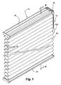
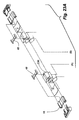
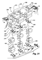
- a retractable covering 12 incorporating the cord lift system 14 of the present invention is illustrated as including a top rail or headrail 16, a bottom rail 18, a flexible cellular fabric material 20 extending between the top and bottom rails, and the lift cord system of the invention.
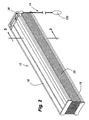
- the covering is shown in an extended position in Fig. 1 and in a retracted position in Fig. 2 .
- the lift cord system of the invention is described in connection with a retractable cellular covering as illustrated, it will be understood by those skilled in the art the system would be useful with most any retractable covering having top and bottom rails with a shade or covering material extending therebetween and with the covering being operable by moving the top or bottom rail relative to the other.
- the top rail 16 of the covering which could in reality assume numerous different forms, is illustrated as being an extruded channel-shaped member with an elongated channel opening downwardly and defining a gap or opening 22 between inturned longitudinal lips 24 which extend the length of the elongated headrail.
- a downwardly opening cavity 26 is thereby formed within the headrail for securing the top of the cellular fabric material 20 and for receiving portions of the lift cord system 14 as will be described in more detail hereafter.
- the bottom rail 18 is similarly illustrated as an elongated extruded member having inturned longitudinal lips 28 extending along the length thereof at the top so as to define an elongated opening 30 through the top.
- An upwardly opening cavity 32 is thereby defined within the bottom rail in which a portion of the fabric material 20 and the lift cord system can be anchored.
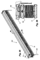
- the fabric material 20 itself can be seen to comprise a plurality of horizontally extending cells 34 of hexagonal transverse cross-section which are secured to adjacent cells along top and bottom surfaces thereof.
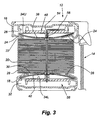
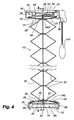
- the material from which the cellular fabric is made retains a crease so the fabric material has a uniform appearance but the cells are transversely collapsible between the expanded position of Fig. 4 and the retracted position of Fig. 3 so the fabric when the covering is retracted usurps only a small vertical space.
- Examples of fabric materials suitable for use in a covering of the type disclosed herein are well known in the art.
- a conventional cord lock 36 is incorporated into the headrail that cooperates with the lift cord system 14 in selectively securing the system in any desired position.
- cord locks are commonly used in the industry and a description thereof is not deemed necessary as it would be well known to those skilled in the art. Suffice it to say the cord lock is designed so that one or more cords passing therethrough can be selectively secured or locked in position so they do not move relative to the headrail but by manipulating the cord lock through movement of the cords in a predetermined direction, the cord lock releases the cords so the cords can slide in either direction through the cord lock allowing the covering to extend or retract.
- the fabric material 20 is secured to the top rail 16 by inserting the uppermost cell 34U of the fabric through the opening 23 in the bottom of the top rail and into the downwardly opening cavity 26 of the top rail and subsequently sliding into the upper cell a rigid or semi-rigid anchor strip 38 of arcuate transverse cross-section, which is wider than the spacing between the lips 24 of the top rail.
- the anchor strip is confined within the cavity of the top rail along with the upper cell of the fabric. The fabric is thereby uniformly suspended from the top rail.
- the lowermost cell 34L in the fabric 20 is similarly connected to the bottom rail 18 by a second anchor strip 40 which is inserted into the lowermost cell after that cell has been positioned within the upwardly opening cavity 32 of the bottom rail so the anchor strip is confined beneath the lips 28 of the bottom rail thereby securing the lowermost cell of the fabric to the bottom rail.
- the cellular fabric has two sets of vertically aligned holes 42 and 44 which extend through each cell and complementary holes 46 through the upper and lower anchor strips with these holes being alignable to receive a portion of the lift cord system as will be described hereafter.
- a pair of slide brackets 48 which are confined within the downwardly opening cavity 26 of the top rail as possibly best seen in Fig. 4 .
- the slide brackets have a transverse main body 50 with enlarged rails 52 perpendicular to the main body at opposite ends to support the slide brackets within the top rail.
- a passage 54 and a downwardly extending hollow neck 56 communicating therewith form part of the main body and define a passageway through which portions of the lift cord system of the invention can pass as will be explained hereafter.
- the slide brackets might be formed so that in one orientation as shown in Fig.
- the cover is configured and sized to fit within a recess 94 defined in an outer surface 96 of the end cap so the cover can not only cover the passages through the end cap but also the components of the lift cord system incorporated therewith as will be described in more detail hereafter.
- cord runs emanating from the tassel extend upwardly through the cord lock 36 and then transversely of the covering through the top rail 16 with one of those runs 102 then extending downwardly through the passage 54 in the first encountered slide bracket 48 and the second of those runs 104 subsequently extending downwardly through the passage 54 in the second encountered slide bracket with the slide brackets of course being separated a predetermined distance commensurate with the spacing of the vertically aligned holes 42 and 44 through the flexible fabric material 20.
- the friction fingers as will be appreciated will hold the position of a cord run relative to a cord bracket associated with the friction finger under normal operating conditions of the covering but a predetermined and relatively strong force applied to either the cord bracket or a run of the lift cord will allow the friction finger to permit sliding movement of a cord thereby.
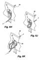
- FIGs. 6H-6K illustrations are made to show how the relative relationship of the anchor cord 88 to the end cap 76 are made to adjust the separation of the coil spring 108 from the other cord bracket 58b.
- the free end 110 of the anchor cord is pulled outwardly so it protrudes from the outer surface 96 of the end cap and the knot is then somewhat loosened so the effective length of the anchor cord can be shortened and the separation of the coil spring from the end cap reduced by pulling the anchor cord.
- the free end of the anchor cord is again inserted back through a passage 86 in the end cap and pulled to cinch the cord and lock it to the end cap at the newly selected position.
- the knot is loosened by extending the free end of the anchor cord back through the end cap so it is on the outside of the end cap and then loosening the knot to allow the effective length of the anchor cord to be lengthened from the end cap to the coil spring before again cinching the anchor cord to the end cap as described previously.
- the coil spring 108 itself is a very strong spring and does not under normal operation of the covering extend at all but merely provides a sliding relationship between the anchor cord 88 and the main cord 98. However, should the covering be put under unusual stress such as might occur when the covering is being retracted but the bottom rail is caught, the spring will give a little to prevent damage to the system.
- a lift system 14 for a covering for an architectural opening which permits the system to be operated in a conventional manner in that the lowering of the tassel 100 will raise the bottom rail 18 and raising of the tassel will lower the bottom rail but the system in addition provides an easy adjustment for leveling the bottom rail relative to the top rail simply by forcibly sliding the cord runs 102 and/or 104 past an associated friction finger 70 in a cord bracket 58 of the bottom rail until the top rail and bottom rail are parallel. Once the rails are adjusted into a parallel relationship, however, the friction fingers and their grip on the cord runs will retain that parallel relationship unless an undue force is placed on the system and should that happen, it can be easily repositioned. Further, the leveling system also provides a convenient way of adjusting the desired maximum spacing between the top rail and the bottom rail and further for securing that desired maximum spacing with an anchoring system.
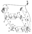
- a diagrammatic illustration shows an embodiment of the invention where there are three vertical runs 116, 118 and 120 of lift cord which might be found, for example, in a covering that was wider than the covering illustrated in Fig. 7 and it was determined that the additional weight in the covering needed an additional run of lift cord for dependable operation.
- like parts have been given identical reference numerals. In the system of Fig.
- a cord loop 122 extends from the tassel 100 where the ends of the main cord forming the loop are secured and with a first run 116 extending downwardly through the first encountered slide bracket 48 and holes 124 in the fabric 20 aligned therewith so it can pass down through a first cord bracket 58c of the bottom rail and from there slidably through a coil spring 126 before returning to the first encountered cord bracket 58c where it passes upwardly across a friction finger 70 on the bracket and from there transversely of the covering into and through a friction finger 70 of a third cord bracket 58d.
- the orientation of the bottom rail can be easily adjusted by forcibly sliding an appropriate cord past a friction finger so the bottom rail and top rail are parallel with each other.
- the desired maximum spacing between the top rail and bottom rail is achieved by adjusting the size of the cord loops above the bottom rail and anchoring the relationship through adjustment to the length of the anchor cord 88.
- the bottom rail can be lowered and raised to extend and retract the large segment of fabric and the middle rail can likewise be lowered or raised to collapse or extend the fabric.
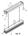
- the small segment of the fabric only engages the middle rail when the middle rail is raised so the middle rail is separable from the small segment ( Figs. 14 and 15 ) when it is lowered in a top down operation of the covering.
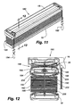
- cord brackets 208 Positioned internally of the middle rail 182 in the lower chamber 194, as seen best in Figs. 12 and 16B , are cord brackets 208 very similar to those used in the bottom rail except they have an upstanding hollow neck 210 that frictionally receives or is otherwise secured to an anchor cap 212 that extends through a passage 214 in the top wall 198 so the closure cap secures the associated anchor bracket to the top wall and within the lower chamber 194 of the middle rail.
- the cord bracket has friction fingers 216 along each of its four sides for cooperating with lift cords in the manner described with the previous embodiments of the invention.
- the middle rail has end caps 218 which substantially match in contour the cross-sectional configuration of the middle rail but provide aesthetic closure to the extruded middle rail.
- the end cap at the right end of the middle rail as viewed in Fig. 16B has a passage 220 therethrough identical to the end cap 76 in the bottom rail so an anchor cord 88 can be adjustably secured to this end cap as described in connection with the embodiment of Fig. 1 .
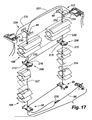
- Fig. 17 it will be appreciated there are two cord loops utilized as lift cords for the embodiment of Figs. 11-17 with the first cord loop 222 being identical to that described in connection with the embodiment of Fig. 1 so the ends of the cord defining the cord loop are secured in the tassel 100 ( Fig.
- a first run 224 of the cord loop extends downwardly through the short fabric 186 and through the central neck 210 of the cord bracket 208 in the middle rail 182 for passage to the aligned cord bracket 58 in the bottom rail 18 where it is slidably connected to a coil spring 226 which in turn is connected at its opposite end to the anchor cord 88 and returns to the tassel 100 in a second run 227 through the other cord bracket 58 in the bottom rail and the cord bracket 208 in the middle rail and subsequently through the aligned slide bracket 48 in the top rail 16.
- the bottom rail is moved identically to that of the embodiment of Fig. 1 through manipulation of the tassel 100 at the right end of the covering.
- the second cord loop is substantially similar to the first cord loop only reversed so the middle rail can be raised and lowered through manipulation of the tassel at the left end of the head rail independently of the movement of the bottom rail by the tassel at the right end of the head rail.
- the middle rail can also be leveled identically to the bottom rail by forcefully changing the elevation of the middle rail by forcing the second loop of lift cord to slide past the friction fingers with which it is engaged.
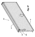
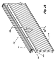
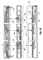
- FIG. 25-32 A still further embodiment of the present invention is shown in Figs. 25-32 .
- the structural components of the covering 252 of this embodiment are identical to that of the embodiment of Figs. 11-17 , but the lift cord system is different.
- the blind illustrated in Figs. 11-17 is relatively narrow and two runs of lift cord are adequate for the weight of the covering.
- one set of lift cords emanate from a tassel (not shown) at the right end of the head rail, which pass through a common cord lock 36 within the end cap of the head rail 16 and similarly a common set of cords emanate from a tassel (not shown) that pass through a common cord lock 36 at the left end of the head rail.
- first cord loop 254 with a first run 256 of the first cord loop extending downwardly through the first-encountered slide bracket 48 and the vertically aligned cord brackets 208 and 58 found in the middle rail and the bottom rail.
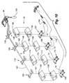
- the first run after passing downwardly through the neck of the first-encountered cord bracket 58 in the bottom rail 18 and subsequently upwardly across a friction finger 70 on the left edge of the cord bracket, it passes within the bottom rail and slidably through one end of a first coil spring 258 in its passage to the cord bracket 58 in the bottom rail that is furtherest left as viewed in Fig. 31 . It extends upwardly through the neck of that cord bracket and vertically in a second run 259 through the large fabric segment 188 and the furthermost left cord bracket 208 of the middle rail 182 and furthermost left slide bracket 48 of the top rail 16 before returning to the tassel at the right end of the head rail.
- the third lift cord 260 emanating from the right end tassel of the covering extends across the head rail 16 and then downwardly through the middle slide bracket 48 and the small fabric segment 186 before extending downwardly through the neck 210 of the cord bracket 208 in the middle rail with the end of this cord segment being anchored to one end of a second coil spring 262.
- the third cord segment 270 anchored in the left tassel extends through the head rail 16 to the middle slide bracket 48 where it passes downwardly therethrough and subsequently through the middle cord bracket 208 in the middle rail 182.
- the cord then extends downwardly through the large fabric segment 188 and through the neck of the middle cord bracket 58 in the bottom rail 18. It then extends upwardly across the right friction finger 70 of the middle cord bracket in the bottom rail and slidably through the end of a third coil spring 272 and subsequently is anchored to the opposite end of the first coil spring 258.
- the third coil spring 272 is itself anchored at its opposite ends with an anchor cord 88 to the end cap at the right end of the bottom rail.
Applications Claiming Priority (2)
| Application Number | Priority Date | Filing Date | Title |
|---|---|---|---|
| US95189407P | 2007-07-25 | 2007-07-25 | |
| US12/176,803 US7832450B2 (en) | 2007-07-25 | 2008-07-21 | Lift cord system for retractable covering |
Publications (2)
| Publication Number | Publication Date |
|---|---|
| EP2019184A2 true EP2019184A2 (de) | 2009-01-28 |
| EP2019184A3 EP2019184A3 (de) | 2014-04-30 |
Family
ID=39917693
Family Applications (1)
| Application Number | Title | Priority Date | Filing Date |
|---|---|---|---|
| EP08252521.3A Withdrawn EP2019184A3 (de) | 2007-07-25 | 2008-07-24 | Zugseilsystem für einziehbare Abdeckung |
Country Status (3)
| Country | Link |
|---|---|
| US (1) | US7832450B2 (de) |
| EP (1) | EP2019184A3 (de) |
| AU (1) | AU2008203269A1 (de) |
Cited By (1)
| Publication number | Priority date | Publication date | Assignee | Title |
|---|---|---|---|---|
| US11459821B2 (en) | 2019-02-05 | 2022-10-04 | Hunter Douglas Inc. | Headrail for an architectural-structure covering |
Families Citing this family (53)
| Publication number | Priority date | Publication date | Assignee | Title |
|---|---|---|---|---|
| US20070074826A1 (en) | 2003-12-22 | 2007-04-05 | Jelic Ralph G | Retractable shade for coverings for architectural openings |
| US20080196843A1 (en) * | 2007-02-15 | 2008-08-21 | Nien Made Enterprise Co., Ltd. | Rail structure for window blinds |
| US7832450B2 (en) * | 2007-07-25 | 2010-11-16 | Hunter Douglas Inc. | Lift cord system for retractable covering |
| TW200745439A (en) * | 2007-08-01 | 2007-12-16 | Ching Feng Blindsind Co Ltd | Curtain balance counter-weight device |
| US8474507B2 (en) | 2008-08-22 | 2013-07-02 | Hunter Douglas Inc. | System for confining lift cords in coverings for architectural openings |
| US8365795B2 (en) * | 2009-11-02 | 2013-02-05 | Horizons Window Fashions, Inc. | Window shade and method of use thereof |
| US8381792B2 (en) * | 2009-11-02 | 2013-02-26 | Horizons Window Fashions, Inc. | Window shade and method of use thereof |
| US20110114269A1 (en) * | 2009-11-13 | 2011-05-19 | Li-Ming Cheng | Window covering for convenient cutting |
| US8763671B2 (en) * | 2009-12-23 | 2014-07-01 | Safe-T-Shade | Cordless covering for architectural opening |
| US8950463B2 (en) | 2009-12-23 | 2015-02-10 | Safe-T-Shade | Cordless coverings for architectural opening having cord enclosures with a swivel feature and methods of assembling such cord enclosures |
| US8967226B2 (en) * | 2009-12-23 | 2015-03-03 | Safe-T-Shade | Architectural cover operating assembly |
| US9187952B2 (en) | 2010-03-02 | 2015-11-17 | Safe-T-Shade | Cordless blind system and retro-fit method |
| US9151110B2 (en) | 2010-03-02 | 2015-10-06 | Safe-T-Shade | Cordless blind systems having cord enclosures with a swivel feature and methods of assembling such cord enclosures |
| EP2575558B1 (de) | 2010-05-28 | 2019-02-06 | Hunter Douglas Inc. | Von drehmotoren angetriebene gebäudeöffnungsabdeckungen |
| DK2585666T3 (da) | 2010-06-23 | 2017-08-21 | Hunter Douglas | Af plast med dobbelte celler opbygget afdækning til brug i arkitektoniske åbninger |
| US20120060329A1 (en) * | 2010-09-15 | 2012-03-15 | Nien Made Enterprise Co., Ltd. | Cord locker and window covering having the cord locker for length adjustment |
| US8459326B2 (en) * | 2011-01-06 | 2013-06-11 | Hunter Douglas, Inc. | Cellular shade assembly and method for constructing same |
| WO2012109147A1 (en) * | 2011-02-07 | 2012-08-16 | Hunter Douglas Inc. | Architectural opening coverings and methods |
| US8505607B2 (en) | 2011-07-19 | 2013-08-13 | Horizons Window Fashions, Inc. | Window shade |
| WO2013033005A1 (en) | 2011-08-26 | 2013-03-07 | Hunter Douglas Inc. | Double pleat cellular shade with vanes |
| KR102022442B1 (ko) | 2011-08-26 | 2019-09-18 | 헌터더글라스인코포레이티드 | 건축물 개구부용 커버링의 셀형 요소들 간의 광 줄무늬를 억제하는 특징부들 |
| US9010399B2 (en) | 2012-05-01 | 2015-04-21 | Horizons Holdings, Llc | Window shade |
| US8561665B2 (en) * | 2011-09-27 | 2013-10-22 | Whole Space Industries Ltd | Safety mechanism for top down bottom up shades |
| BR112014007887B1 (pt) | 2011-10-03 | 2021-02-09 | Hunter Douglas Inc. | aparelho de controle de cobertura para abertura arquitetônica |
| US20130087296A1 (en) * | 2011-10-07 | 2013-04-11 | Willis Jay Mullet | Automatic releasable top down shade system and method |
| NL2008371C2 (en) * | 2012-02-28 | 2013-09-02 | Hunter Douglas Ind Bv | A covering for an architectural opening. |
| US9316049B2 (en) | 2012-03-01 | 2016-04-19 | Hunter Douglas, Inc. | Collapsible cellular shade assembly and method for constructing same |
| US8540006B1 (en) | 2012-05-08 | 2013-09-24 | SAFE-T-SHADE, Inc. | Apparatuses, systems and methods for locking lift cords used to lift architectural opening coverings |
| US20130312921A1 (en) * | 2012-05-25 | 2013-11-28 | Ching Feng Home Fashions Co., Ltd. | Curtain cable positioing device |
| US9988837B2 (en) | 2012-07-13 | 2018-06-05 | Hunter Douglas Industries Switzerland Gmbh | Variable force brake for a window covering operating system |
| US9217282B2 (en) | 2012-07-13 | 2015-12-22 | Newell Window Furnishings, Inc. | Window covering and operating system |
| US9759008B2 (en) * | 2012-12-06 | 2017-09-12 | Hunter Douglas Inc. | End cap for a rail for a window covering |
| US9357868B2 (en) * | 2012-12-06 | 2016-06-07 | Hunter Douglas Inc. | Skew adjustment mechanism for a window covering |
| TWM452720U (zh) * | 2012-12-18 | 2013-05-11 | Ching Feng Home Fashions Co | 可變換蜂巢簾及羅馬簾結構 |
| US8931540B2 (en) * | 2013-03-13 | 2015-01-13 | Lutron Electronics Co., Inc. | Window treatment having an adjustable bottom bar |
| USD734061S1 (en) | 2013-04-01 | 2015-07-14 | Hunter Douglas Inc. | Portion of a cellular shade component |
| USD734060S1 (en) | 2013-04-01 | 2015-07-14 | Hunter Douglas Inc. | Cellular shade component |
| USD743183S1 (en) * | 2013-06-27 | 2015-11-17 | Oceanair Marine Ltd | Extendable window blind |
| USD764836S1 (en) | 2014-09-08 | 2016-08-30 | Hunter Douglas Inc. | Covering for an architectural opening having multiple columns of double cells |
| US9719296B1 (en) | 2014-10-06 | 2017-08-01 | Safe-T-Shade | Apparatuses and systems for selectively locking lift cords used to lift architectural opening coverings |
| US9593528B2 (en) | 2014-11-01 | 2017-03-14 | Hunter Douglas, Inc. | Light blocking element for a covering for an architectural opening |
| USD789116S1 (en) | 2014-12-09 | 2017-06-13 | Hunter Douglas Inc. | Sample deck for selecting a covering for an architectural opening |
| US20160222722A1 (en) | 2015-02-03 | 2016-08-04 | Newell Window Furnishings, Inc. | Window covering and operating system |
| US10392859B2 (en) | 2016-02-18 | 2019-08-27 | Hunter Douglas Inc. | Rail for an architectural covering |
| US10024101B2 (en) * | 2016-11-29 | 2018-07-17 | Lumino, Inc. | Bottom rail for a cordless blind |
| JP6577538B2 (ja) * | 2017-08-17 | 2019-09-18 | 立川ブラインド工業株式会社 | 横型ブラインド及び横型ブラインド用ボトムレール |
| USD944020S1 (en) * | 2019-10-03 | 2022-02-22 | Molo Design, Ltd. | Adjustable partition |
| USD951662S1 (en) * | 2019-10-03 | 2022-05-17 | Molo Design, Ltd. | Adjustable partition |
| US11891855B2 (en) | 2020-01-28 | 2024-02-06 | Levolor, Inc. | Leveling assembly for adjusting the levelness of a bottom rail of a covering for an architectural structure |
| US11441352B2 (en) | 2020-02-20 | 2022-09-13 | Lafayette Venetian Blind, Inc. | Dual cordless retractable shade system with transitional shade materials for architectural openings |
| TWM603727U (zh) * | 2020-05-19 | 2020-11-11 | 黃昱瑋 | 提拉式窗簾組 |
| CN213573799U (zh) * | 2020-09-14 | 2021-06-29 | 太仓敬富塑胶制品有限公司 | 磁吸式蜂巢帘 |
| US20230130366A1 (en) * | 2021-10-26 | 2023-04-27 | Plicell Tekstil Sanayi Ve Ticaret Anonim Sirketi | Pleated and honeycomb blinds system |
Citations (1)
| Publication number | Priority date | Publication date | Assignee | Title |
|---|---|---|---|---|
| US20020195212A1 (en) | 2001-06-21 | 2002-12-26 | Osinga Anne J. | Equalizing connector for window covering pull cords |
Family Cites Families (17)
| Publication number | Priority date | Publication date | Assignee | Title |
|---|---|---|---|---|
| US2421505A (en) * | 1945-02-13 | 1947-06-03 | Hunter Eng Co | Bottom rail assembly for venetian blinds |
| US3280890A (en) * | 1964-12-24 | 1966-10-25 | Levolor Lorentzen Inc | Venetian-blind construction for taking up lift-cord slack |
| US4557309A (en) * | 1983-08-24 | 1985-12-10 | Verosol Usa Inc. | Sun blind |
| US4852627A (en) | 1987-04-13 | 1989-08-01 | Daylighting, Inc. | Closed loop control system for shade assembly |
| US5195569A (en) | 1987-04-13 | 1993-03-23 | Daylighting, Inc. | Closed loop control system for shade assembly |
| US4813468A (en) * | 1987-09-08 | 1989-03-21 | Hunter Douglas Inc. | Two and three position over-under window shade |
| US5002112A (en) | 1989-06-30 | 1991-03-26 | Comfortex Corporation | Suspension and actuation systems for specialty window shades |
| US5170108A (en) | 1991-01-31 | 1992-12-08 | Daylighting, Inc. | Motion control method and apparatus for motorized window blinds and and the like |
| DE29613845U1 (de) * | 1996-08-09 | 1996-10-17 | Bloecker Karl H Gmbh & Co | Faltstore |
| DE69839138T2 (de) * | 1997-07-14 | 2009-02-05 | Hunter Douglas Industries B.V. | Store oder Jalousie für ein Fenster |
| US6053236A (en) * | 1998-10-26 | 2000-04-25 | Ren Judkins | Length adjustable bottomrail having releasable ladder retainer |
| US6530415B2 (en) * | 2001-06-11 | 2003-03-11 | Chia-Tien Wu | Force reducing device and method for adjusting shutter ropes |
| US6550522B1 (en) | 2002-03-28 | 2003-04-22 | Dennis R. Lennon | Level adjuster for window shades |
| US6948216B2 (en) * | 2002-06-17 | 2005-09-27 | Hunter Douglas Inc. | Window covering with improved anchor for operating cord |
| US7311132B2 (en) * | 2004-01-17 | 2007-12-25 | Comfortex Corporation | Self-equalizing corded window covering and breakaway coupling member for same |
| US7766068B2 (en) * | 2005-03-01 | 2010-08-03 | Faber A/S | Adjustable bottom rail for venetian blinds and use of adjustment means therefor |
| US7832450B2 (en) * | 2007-07-25 | 2010-11-16 | Hunter Douglas Inc. | Lift cord system for retractable covering |
-
2008
- 2008-07-21 US US12/176,803 patent/US7832450B2/en not_active Expired - Fee Related
- 2008-07-22 AU AU2008203269A patent/AU2008203269A1/en not_active Abandoned
- 2008-07-24 EP EP08252521.3A patent/EP2019184A3/de not_active Withdrawn
Patent Citations (2)
| Publication number | Priority date | Publication date | Assignee | Title |
|---|---|---|---|---|
| US20020195212A1 (en) | 2001-06-21 | 2002-12-26 | Osinga Anne J. | Equalizing connector for window covering pull cords |
| US7383871B2 (en) | 2001-06-21 | 2008-06-10 | Hunter Douglas Industries Bv | Equalizing connector for window covering pull cords |
Cited By (1)
| Publication number | Priority date | Publication date | Assignee | Title |
|---|---|---|---|---|
| US11459821B2 (en) | 2019-02-05 | 2022-10-04 | Hunter Douglas Inc. | Headrail for an architectural-structure covering |
Also Published As
| Publication number | Publication date |
|---|---|
| AU2008203269A1 (en) | 2009-02-12 |
| EP2019184A3 (de) | 2014-04-30 |
| US7832450B2 (en) | 2010-11-16 |
| US20090025888A1 (en) | 2009-01-29 |
Similar Documents
| Publication | Publication Date | Title |
|---|---|---|
| US7832450B2 (en) | Lift cord system for retractable covering | |
| CA2748834C (en) | Retractable covering for doorways, archways, and the like | |
| US20110005690A1 (en) | Window Covering | |
| US6782937B2 (en) | Framed covering for architectural opening | |
| US7252132B2 (en) | Window covering | |
| US20050022947A1 (en) | Venetian blind | |
| JP2007500296A (ja) | ウィンドウカバー | |
| EP3080378B1 (de) | Jalousie | |
| CA2551369A1 (en) | Control system for vertical covering for architectural openings | |
| US7628195B2 (en) | Nonretractable covering for architectural openings | |
| CA2365977C (en) | Ladder operated covering with fixed vanes for architectural openings | |
| CA2529118C (en) | Multiple tier venetian blind | |
| CA2589480C (en) | Operating system for arched covering for architectural opening | |
| US20070246170A1 (en) | Combination window or door covering | |
| US9303451B2 (en) | System for pivoting a blind slat | |
| CA2638209A1 (en) | Lift cord system for retractable covering | |
| US7240714B2 (en) | System for suspending a free-hanging covering for an architectural opening | |
| US20070175594A1 (en) | Coverings for architectural openings with cord lock | |
| US11441352B2 (en) | Dual cordless retractable shade system with transitional shade materials for architectural openings | |
| US20040194898A1 (en) | Venetian blind having lift cord stopper | |
| EP1512826B1 (de) | Endstück für einen Vorhang mit einer geneigten Seitenkante | |
| CA3150930A1 (en) | Roman blind with flexible flat member | |
| GB2371071A (en) | Adjustable head rail |
Legal Events
| Date | Code | Title | Description |
|---|---|---|---|
| PUAI | Public reference made under article 153(3) epc to a published international application that has entered the european phase |
Free format text: ORIGINAL CODE: 0009012 |
|
| AK | Designated contracting states |
Kind code of ref document: A2 Designated state(s): AT BE BG CH CY CZ DE DK EE ES FI FR GB GR HR HU IE IS IT LI LT LU LV MC MT NL NO PL PT RO SE SI SK TR |
|
| AX | Request for extension of the european patent |
Extension state: AL BA MK RS |
|
| RAP1 | Party data changed (applicant data changed or rights of an application transferred) |
Owner name: HUNTER DOUGLAS INC. |
|
| RIC1 | Information provided on ipc code assigned before grant |
Ipc: E06B 9/388 20060101ALI20131127BHEP Ipc: E06B 9/262 20060101AFI20131127BHEP Ipc: E06B 9/32 20060101ALI20131127BHEP |
|
| PUAL | Search report despatched |
Free format text: ORIGINAL CODE: 0009013 |
|
| AK | Designated contracting states |
Kind code of ref document: A3 Designated state(s): AT BE BG CH CY CZ DE DK EE ES FI FR GB GR HR HU IE IS IT LI LT LU LV MC MT NL NO PL PT RO SE SI SK TR |
|
| AX | Request for extension of the european patent |
Extension state: AL BA MK RS |
|
| RIC1 | Information provided on ipc code assigned before grant |
Ipc: E06B 9/262 20060101AFI20140326BHEP Ipc: E06B 9/388 20060101ALI20140326BHEP Ipc: E06B 9/32 20060101ALI20140326BHEP |
|
| AKY | No designation fees paid | ||
| AXX | Extension fees paid |
Extension state: MK Extension state: RS Extension state: BA Extension state: AL |
|
| REG | Reference to a national code |
Ref country code: DE Ref legal event code: R108 |
|
| REG | Reference to a national code |
Ref country code: DE Ref legal event code: R108 Effective date: 20150107 |
|
| STAA | Information on the status of an ep patent application or granted ep patent |
Free format text: STATUS: THE APPLICATION IS DEEMED TO BE WITHDRAWN |
|
| 18D | Application deemed to be withdrawn |
Effective date: 20141031 |