EP2019161A1 - Household washing machine with improved detergent drawer - Google Patents
Household washing machine with improved detergent drawer Download PDFInfo
- Publication number
- EP2019161A1 EP2019161A1 EP07112980A EP07112980A EP2019161A1 EP 2019161 A1 EP2019161 A1 EP 2019161A1 EP 07112980 A EP07112980 A EP 07112980A EP 07112980 A EP07112980 A EP 07112980A EP 2019161 A1 EP2019161 A1 EP 2019161A1
- Authority
- EP
- European Patent Office
- Prior art keywords
- push
- axis
- drawer
- pivots
- front panel
- Prior art date
- Legal status (The legal status is an assumption and is not a legal conclusion. Google has not performed a legal analysis and makes no representation as to the accuracy of the status listed.)
- Granted
Links
- 239000003599 detergent Substances 0.000 title claims abstract description 21
- 238000005406 washing Methods 0.000 title claims abstract description 13
- 238000001035 drying Methods 0.000 claims abstract 2
- 238000003780 insertion Methods 0.000 claims description 5
- 230000037431 insertion Effects 0.000 claims description 5
- 230000003993 interaction Effects 0.000 claims description 2
- 206010013710 Drug interaction Diseases 0.000 claims 1
- 230000007246 mechanism Effects 0.000 description 10
- 230000000284 resting effect Effects 0.000 description 4
- 230000000694 effects Effects 0.000 description 2
- 230000006872 improvement Effects 0.000 description 2
- 230000009471 action Effects 0.000 description 1
- 230000004048 modification Effects 0.000 description 1
- 238000012986 modification Methods 0.000 description 1
Images






Classifications
-
- D—TEXTILES; PAPER
- D06—TREATMENT OF TEXTILES OR THE LIKE; LAUNDERING; FLEXIBLE MATERIALS NOT OTHERWISE PROVIDED FOR
- D06F—LAUNDERING, DRYING, IRONING, PRESSING OR FOLDING TEXTILE ARTICLES
- D06F39/00—Details of washing machines not specific to a single type of machines covered by groups D06F9/00 - D06F27/00
- D06F39/02—Devices for adding soap or other washing agents
Definitions
- the present invention relates to an improved, preferably household washing machine, provided with a front drawer for the introduction and delivery of products for the washing, as detergents, softeners and so on.
- Such drawer which is widely known, and that in the following will be briefly called “detergent drawer”, is realized and lodged in a way to be easily extractable and introduced in the machine with an horizontal movement.
- Such drawer can be moved into and out of the machine without specific problems; however, in order to facilitate its control by the user, and also to make the front panel of it more aligned with the machine front wall, essentially for aesthetic reasons, sometimes the drawer is provided with a mechanism called "push-push”, per se known, which offers the possibility of disengaging the drawer from the introduced position simply by a light front pushing.
- the drawer when the drawer is being introduced for said short over-run, it may happen an annoying drawback; in the facts, with ref. to fig. 1 , it may happen that the machine top is composed of two separate flat elements, i. e. of a flat rear surface 1 and of a front frame 2, extending for the whole machine width.
- Said two elements 1 and 2 are separated by a groove 3.
- the drawer front panel 4 is, for aesthetic reasons, provided with a top portion 5 which is flat, horizontal, extending back at the level of said machine top, and interrupting a front part of said frame 2 until said groove 3, as clearly shown in figure 1 .
- a clothes washing machine provided with a top surface, with a detergent drawer, and an associated push-push mechanism, placed on the machine upper front wall
- said drawer being provided with a front panel with a top portion extending at least partially and horizontally towards the machine flat rear surface, and with a groove horizontally extending between said flat rear surface and said top portion of the front panel of said drawer, that will eliminate, or at least reduce the drawback of the collision between said flat rear surface and said top portion of the detergent drawer during the over-run of the push-push mechanism.
- a front-loader washing machine comprises:
- the machine and specifically the detergent drawer is provided with means and devices which allow to avoid the described drawback, through a simple lifting of the drawer front panel 4 , that is a raising movement of said front panel when it is being fully inserted for the whole over-run of the push-push.
- the invention may be implemented according to the following profitable embodiment: with ref. to the figures 4 , and 4A said detergent drawer comprises a front structure 10 placed just behind said front panel 4, into said structure being arranged:
- Said first rotation element 13 is also provided with a second pair of pivots 16, 17 which are coaxial, the relevant axis X2 being parallel to said first axis X1, and the inner wall of said front panel 4 is correspondently provided with respective cylindrical lodgings 18, 19 which are coaxial, placed and sized so to be able of lodging respective said pivots 16, 17.
- Said first rotation element is moreover sized and arranged with such an inclination that its contiguous but non aligned pivots 14 and 16 are so placed that the pivot 16 is arranged in a higher and fore position with respect to the respective pivot 14, as schematically shown in fig. 6 ; the same is realized also for the pivot 15 with respect to the corresponding contiguous and not coaxial pivot 17.
- said rotation is turned into a lifting movement, further over a backwards movement, of the pivots 16 and 17, said lifting movement being so transferred, across the lodgings 18 and 19, to the front panel 4, and particularly to the top portion 5, making it to raise, as schematically shown in fig. 3 .
- the push-push mechanism will be implemented by a first device firm with the front panel 4, and by a second corresponding device connected to the machine main frame, in such a way that the mechanism itself can act only on the front panel 4 and not on the detergent drawer itself.
- Said second rotation element 20 is moreover shaped and oriented with an inclination such that the two contiguous and not aligned pivots 23 and 25, (belonging to respective and different couples al pivots), are placed in such a way that the pivots 25, 26 are arranged in a higher and fore position with respect to the respective contiguous pivots 23, 24 of said third couple of pivots (figg. 4, 4A, 6 and 7).
- third axis X3 and fourth axis X4 which are parallel, are also parallel to said two axis X1 and X2.
- the distance R between the first and the third axis X1 and X3 is made equal to the distance between the axis X2 of the lodgings 16, 17, and the axis X4 of the lodgings 21, 22.
- an inclined edge 32 is formed, and on at least on one of said rotation elements 13 a corresponding contact surface 33 is formed too, which is able of being touched by said inclined edge, so that it can be pushed by a force acting towards the side wall of the machine, caused by the reciprocal interaction between said elements 32 and 33 when said rotation element 13 is pushed backwards during the final push-push run.
- such inclined edge 32 shows an inclination with a not null angle a with respect to a vertical plane P1 orthogonal to the machine front wall; in such a way the contact surface 33 of the rotation element 13 acts as a tappet, and slides on said inclined edge 32, here working as a cam.
- the final effect is that, during the rotation of the rotation element 13, when pushing the front panel, schematically represented by the figures 10 and 11 in the initial and final orientations, said element 13 is urged to move towards the direction of said inclined edge 32, and therefore, in the embodiment of figures 12 and 13 , and also represented in the fugures 14 and 15, towards the choose side wall, with the result of also departing and separating said side rim 30 of the front panel 4 from said rim 31, as desired to avoid the side collision.
- the front panel 4 rotation which basically rotates being driven by the axis X1 and X2, takes also a sideward component, further to the upward component as just described.
- Fig 18 is shown a washing machine detail referring to a detergent drawer and related front panel, according to a preferred embodiment of the invention as previously described.
- the invention configuration is such that the lifting, and possibly the side movement of the detergent drawer begins from the position wherein the drawer is closed and at a rest; in the fact in this condition the drawer position results to be perfectly aligned with the remaining contiguous machine surfaces, i. e. the top and the front wall.
Landscapes
- Engineering & Computer Science (AREA)
- Textile Engineering (AREA)
- Drawers Of Furniture (AREA)
- Main Body Construction Of Washing Machines And Laundry Dryers (AREA)
- Washing And Drying Of Tableware (AREA)
Abstract
Said machine is provided with means able of automatically giving said front panel a lifting movement, and a contemporary lateral movement when it takes the end inner position of said push-push arrangement.
Description
- The present invention relates to an improved, preferably household washing machine, provided with a front drawer for the introduction and delivery of products for the washing, as detergents, softeners and so on.
- Such drawer, which is widely known, and that in the following will be briefly called "detergent drawer", is realized and lodged in a way to be easily extractable and introduced in the machine with an horizontal movement.
- Such drawer can be moved into and out of the machine without specific problems; however, in order to facilitate its control by the user, and also to make the front panel of it more aligned with the machine front wall, essentially for aesthetic reasons, sometimes the drawer is provided with a mechanism called "push-push", per se known, which offers the possibility of disengaging the drawer from the introduced position simply by a light front pushing.
- Inversely in order to insert said drawer in its seat, it needs to be introduced by a very short over-run, usually of 1 to 3 mm., beyond its final position, in order to allow the mechanism itself of automatically resetting; after that an elastic means of the same mechanism takes ahead the drawer until the final position is reached.
- However when the drawer is being introduced for said short over-run, it may happen an annoying drawback; in the facts, with ref. to
fig. 1 , it may happen that the machine top is composed of two separate flat elements, i. e. of a flatrear surface 1 and of afront frame 2, extending for the whole machine width. - Said two
elements groove 3. - The
drawer front panel 4 is, for aesthetic reasons, provided with atop portion 5 which is flat, horizontal, extending back at the level of said machine top, and interrupting a front part of saidframe 2 until saidgroove 3, as clearly shown infigure 1 . - With such embodiment it comes difficult, and sometimes even impossible, to provide the drawer with the cited push-push mechanism, as when the drawer is introduced and in resting condition, as shown in the figure, the
rear rim 6 of saidframe 2 does not interfere with thefront rim 7 of said flatrear surface 1; however during the short over-run required by said push-push mechanism, it obviously happens that saidrims groove 3, until they come into collision, as schematically shown infig. 2 . - It would therefore be desirable, and is actually a main purpose of the present invention, to provide a clothes washing machine provided with a top surface, with a detergent drawer, and an associated push-push mechanism, placed on the machine upper front wall, said drawer being provided with a front panel with a top portion extending at least partially and horizontally towards the machine flat rear surface, and with a groove horizontally extending between said flat rear surface and said top portion of the front panel of said drawer, that will eliminate, or at least reduce the drawback of the collision between said flat rear surface and said top portion of the detergent drawer during the over-run of the push-push mechanism.
- According to the present invention, this and further aims are reached in a washing machine incorporating the characteristics as recited in the appended claims and including such operating means as described below by mere way of non-limiting example with reference to the accompanying drawings, in which:
-
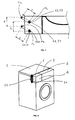
Fig. 1 is a perspective view of a front wall of a washing machine with a detergent drawer and related front panel according to the prior art, -
Fig. 2 is a perspective view on the top surface of a machine, showing the explained drawback, -
Fig. 3 is a symbolical view of a vertical transversal section of the machine infig. 2 according to the invention, and with the drawer fully inserted, -
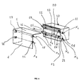
Fig. 4 shows a perspective, transparent and partially exploded views of a detergent drawer according to the invention, -
Fig. 4A shows an exploded view offig. 4 , -
Fig. 5 and 5A do show two plan views of two respective components of a detergent drawer according to the invention, -
Fig. 6 shows a plan vertical and side section of the drawer according to the invention, -
Fig. 7 shows some specific features offig. 6 , -
Fig. 8 show a perspective side and outer view of a side wall of a washing machine provided with a detergent drawer and related front panel according to the prior art, -
Fig. 9 shows a plan top and transparent view of an improved embodiment of a detergent drawer according to the invention, -
Fig. 10 shows a perspective view of the embodiment infig. 9 , with the drawer in its resting position, -
Fig. 11 show the view offig. 10 , but the drawer pressed in the end position of the push-push run, -
Fig. 12 and 13 show two top views of the machine according to an improved embodiment of the invention, respectively with the drawer inserted in the resting position, and fully pressed in the end position of the push-push run, -
Figures 14 and 15 do show the machine in the conditions respectively offigures 12 and 13 , but represented in the side vertical views. -
Figures 16 and 17 do show a symbolic and top representation of a different embodiment of a drawer according to the invention. -
Fig. 18 shows a view in schematic perspective of a washing machine detail referring to a detergent drawer and related front panel according to the invention. - With ref. to
figures 1 and3 , a front-loader washing machine according to the prior art comprises: - a top wall, consisting of a flat
rear surface 1 and afront frame 2, - a detergent drawer placed on the front and top wall of the machine, and provided with a
vertical front panel 4 with atop portion 5 at least partially extending on the machine top wall, - a push-push mechanism, which is known per se and not shown, which allows the engaging and disengaging of said drawer within the related seat inside the machine.
- According to the invention, the machine and specifically the detergent drawer is provided with means and devices which allow to avoid the described drawback, through a simple lifting of the
drawer front panel 4 , that is a raising movement of said front panel when it is being fully inserted for the whole over-run of the push-push. - When said panel is lifted, its
top portion 5 is obviously lifted too, and as a final consequence, due to such lifting itsrear rim 6 is being made to overcome and slip over thefront rim 7 of the flatrear surface 1, so avoiding the collision (Fig. 3 ). - The invention may be implemented according to the following profitable embodiment: with ref. to the
figures 4 , and4A said detergent drawer comprises afront structure 10 placed just behind saidfront panel 4, into said structure being arranged: - two
cylindrical lodgings - a first rotation element 13 (
fig. 5 ), flat and rectangular, but it can also show a trapezoidal shape, wherein two contiguous angles are provided with two respectivecoaxial pivots first rotation element 13 may so rotate with respect to saidfront structure 10, around said twopivots respective lodgings - Said
first rotation element 13 is also provided with a second pair ofpivots front panel 4 is correspondently provided with respectivecylindrical lodgings pivots - Said first rotation element is moreover sized and arranged with such an inclination that its contiguous but non aligned
pivots pivot 16 is arranged in a higher and fore position with respect to therespective pivot 14, as schematically shown infig. 6 ; the same is realized also for thepivot 15 with respect to the corresponding contiguous and notcoaxial pivot 17. - During the push-push over-run, when the
front panel 4 is being pressed from the resting position, the drawer is then inserted in its normal operating position, thestructure 10 is stopped and therefore the pressure on saidpanel 4 is being transferred, across thelodgings e 17 of saidfirst rotation element 13; the force acting on saidpivots Fig. 7 ), the latter making thepivots pivots respective lodgings structure 10. - Therefore said rotation is turned into a lifting movement, further over a backwards movement, of the
pivots lodgings front panel 4, and particularly to thetop portion 5, making it to raise, as schematically shown infig. 3 . - So the requested panel lifting action is achieved, which is done in the same time of drawer insertion during the push-push over-run.
- It is supposed here useful to remind that the
panel 4 is connected not firmly to thestructure 10, but only through thepivots panel 4 itself. - Obviously the push-push mechanism, not shown as well know in the art, will be implemented by a first device firm with the
front panel 4, and by a second corresponding device connected to the machine main frame, in such a way that the mechanism itself can act only on thefront panel 4 and not on the detergent drawer itself. - The just described solution offers some profitable improvements: in the facts it comes that the front panel results pivoted to the
coaxial pivots respective lodgings - In order to avoid such a problem an improvement is made, consisting in carrying out a second rotation element 20 (
Figures 4 to 6 ), fully identical to the first one 13, and mounted on saidstructure 10 and connected to saidfront panel 4 with the same criterion. - Therefore, with ref. to said figures, the following items are defined:
- into said
structure 10, two furthercylindrical lodgings - in said
second rotation element 20, rotating around saidstructure 10, and comprising four corners, a third couple ofpivots pivots cylindrical lodgings second rotation 20 element being able to rotate trough said tworespective pivots
Said second rotation element is provided with a fourth couple ofpivots cylindrical lodgings front panel 4. - Said
second rotation element 20 is moreover shaped and oriented with an inclination such that the two contiguous and not alignedpivots pivots contiguous pivots - Furthermore said third axis X3 and fourth axis X4, which are parallel, are also parallel to said two axis X1 and X2.
- It comes also profitable (
fig. 7 ) that the distance S, between said first and second axis X1 and X2, be made equal to the distance given to the lodgings between the third and the fourth axis X3 and X4. - Moreover the distance R between the first and the third axis X1 and X3 is made equal to the distance between the axis X2 of the
lodgings lodgings - This allows to place these axis in such a ay that, in an orthogonal section as shown in
fig. 7 , the sections of said axis are being exactly placed in the corners of a parallelogram; it allows that during the final push-push insertion run, the said front panel may only be moved backwards and upwards, but remaining always parallel to itself. - The proposed solution fully solves the initial problem; however it was observed that a further problem may be generated, i. e. the
side rim 30 of thefront panel 4, even if lifted, in its final run may collide with therim 31 which is the prolongation, on the machine side wall, of thefore rim 7 of the flatrear surface 1, as shown infig. 8 . - In order to overcome such problem, and with ref. to the
figures 9 and10 , on saidstructure 10 aninclined edge 32 is formed, and on at least on one of said rotation elements 13 acorresponding contact surface 33 is formed too, which is able of being touched by said inclined edge, so that it can be pushed by a force acting towards the side wall of the machine, caused by the reciprocal interaction between saidelements rotation element 13 is pushed backwards during the final push-push run. - In order to assure such effect of side movement of the front panel, together with the upwards movement, such
inclined edge 32 shows an inclination with a not null angle a with respect to a vertical plane P1 orthogonal to the machine front wall; in such a way thecontact surface 33 of therotation element 13 acts as a tappet, and slides on saidinclined edge 32, here working as a cam. - The final effect is that, during the rotation of the
rotation element 13, when pushing the front panel, schematically represented by thefigures 10 and 11 in the initial and final orientations, saidelement 13 is urged to move towards the direction of saidinclined edge 32, and therefore, in the embodiment offigures 12 and 13 , and also represented in thefugures side rim 30 of thefront panel 4 fromsaid rim 31, as desired to avoid the side collision. - To sum up, the movement of said element is oriented both upwards and sideward.
- Obviously the solution, just referred to one of said rotation element, identified as 13, is identically extendable and applicable also to the
second rotation element 20 and to a corresponding edge of thestructure 10, in a fully similar way. - The purpose of such extension is to allow also the side movement of the
front panel 4, through a simple movement of translation, and without any modification of the orientation of the front panel itself. - The just described solutions to move the front panel with an upwards and sideward movement in the over-run step of the push-push may be achieved also with the following embodiment, which very shortly is based on the following features: the
front panel 4 upwards and sideward movement is now implemented by a solution based on the fact that the push-push over-run alone may create in a contemporary way both the movements. - Reference is here made to the
figures 16 and 17 , which show transparent top views of thestructure 10 and of therotating elements front panel 4 according to an improved embodiment. - It was observed that, in order of achieving the result of moving the control panel both upwards and sideward together with its pushing in the end position of the push-push run, it is sufficient to provide the
structure 10 with lodgings and pivots in a fully similar way as described, and the same for thefront panel 4, however with a main difference: in the facts the axis X1, X2, X3 and X4 offigure 1 to 7 even if remaining parallel and on the horizontal plane, are not more oriented parallel also to the machine front wall, but they are slightly inclined respect to it with a proper angle b, as shown in saidfigures 16 and 17 , showing two schematic top views of thestructure 10 and of therotation element 13, respectively with the drawer closed and at a rest, and with the drawer in the extreme push-push run, that is with thepanel 4 slightly shifted towards the extreme side wall of the machine. - Therefore the
front panel 4 rotation, which basically rotates being driven by the axis X1 and X2, takes also a sideward component, further to the upward component as just described. - And so the desired result of a combined movement upwards and sideward of the front panel 4 n the push-push over-run is achieved.
- For sake of brevity and clarity a whole repetition of the features just explained is avoided, being understood that the sole difference resides in the fact that in the present embodiment the axis Xa1, Xa2, corresponding to the axis X1 and X2 in the embodiment previously explained, are horizontal but slightly inclined, just for the angle b , with respect to the machine front wall.
- For simplicity it is here omitted the fully equivalent description in the case, already previously explained, that two distinct but equal rotation elements, in order to realize a parallelogram, are provided.
- In
Fig 18 is shown a washing machine detail referring to a detergent drawer and related front panel, according to a preferred embodiment of the invention as previously described. - At this point the man skilled in the art will have surely already guessed that the invention configuration is such that the lifting, and possibly the side movement of the detergent drawer begins from the position wherein the drawer is closed and at a rest; in the fact in this condition the drawer position results to be perfectly aligned with the remaining contiguous machine surfaces, i. e. the top and the front wall.
- Only during the push-push over-run said
front panel 4 has to be handled and reoriented as described, and therefore the described devices are realized, sized, and reciprocally arranged mounted in a way that the described upwards and sideward movement of thefront panel 4 can be achieved in the same time and fully automatically, and begins and stops during the push-push over-run step, and in said step only.
Claims (9)
- Front loader washing or washing-drying machine comprising:- a top surface,- a detergent drawer placed on the machine front upper wall, and provided with a front panel (4) with a top portion (5) at least partially extending on said top surface itself,- means for the engagement and dis-engagement of said drawer into and from a related lodgement by a pushing on said front panel, said means comprising a push-push arrangement, composed by two devices able of interact each other, whose one device is mounted on said drawer, and the second device is firm with the machine main frame, characterized in that it is provided with means able of automatically giving said front panel a lifting movement, when it takes the extreme inner position of said push-push arrangement.
- Washing machine according to claim 1, characterized in that said detergent drawer comprises a structure (10) which includes:- two cylindrical lodgings (11, 12) placed on a common first axis (X1) and placed at a pre-defined distance, preferably similar to the drawer width, said first axis being substantially horizontal,- a firs rotating element (13) comprising four corners, having two coaxial pivots (14, 15) arranged on two respective contiguous corners, said pivots being able to be engaged with two respective cylindrical lodgings (11, 12), said first rotation element being able of rotating with said two coaxial pivots with respect to said structure,- said first rotation element being provided with two coaxial pivots (16, 17), whose common axis (X2) is parallel to said first axis (X1), able to be engaged with respective cylindrical lodgings (18, 19) placed on the inner side of said front panel (4),- said first rotation element being shaped and oriented with an inclination such as two contiguous, corresponding and not aligned pivots (14, 16), are placed in a way that the pivot (16) on said second axis (X2) is placed in higher and fore position with respect to the contiguous pivots (14) on said first axis (X1).
- Machine according to claim 2, characterized in that said first and second axis (X1, X2) are oriented in a way essentially parallel to plane of the machine front wall.
- Machine according to any of the claims 3, characterized in that said detergent drawer comprises:- two further cylindrical lodgings (21, 22) placed on a common third axis (X3) and placed at a pre-defined distance, preferably similar to the drawer width, said third axis being substantially horizontal and oriented transversal to the insertion direction of said drawer,- a second rotating element (20) comprising four corners, having two coaxial pivots (23, 24) arranged on two respective contiguous corners, said pivots being able to be engaged with two respective cylindrical lodgings (21, 22), said second rotation element being able of rotating with said two coaxial pivots with respect to said structure,- said second rotating element being provided with two coaxial pivots (25, 26), whose common axis (X4) is parallel to said third axis (X3), able to be engaged with respective cylindrical lodgings (27, 28) placed on the inner side of said front panel (4),- said second rotation element being shaped and oriented with an inclination such as two contiguous, corresponding and not aligned pivots (23, 25), are placed in a way that the pivot (25) on said fourth axis (X4) is placed in higher and fore position with respect to the contiguous pivots (23) on said third axis (X3).
- Machine according to one of the preceding claims, characterized in that said means for the front panel (4) lifting are able to give the panel itself a contemporary sideward movement when it is pushed in the end position of the push-push run.
- Machine according to claim 6, characterized in that said structure (10) comprises an edge (32) which is inclined outwards by a not null angle (a) with respect to a vertical plane (P1) orthogonal to the machine front wall, and that at least one of said one of said rotating elements (13) is provided with respective contact surface (33) able of touching and sliding on said inclined edge (32) so as to be urged towards a side movement caused by the inter-action between said inclined edge (32) and said contact surface (33).
- Machine according to claims 5 or 6, characterized in that said first and second axis (X1, X2) are substantially oriented on an inclined way (b) with respect to the machine front wall.
- Machine according to any of the preceding claims, characterized in that said first and second rotating elements (13, 20) are basically identical, and that the four pivots (14, 16, 23, 25) which are placed on a same side of said drawer, and the four corresponding pivots (15, 17, 24, 26) placed on the opposite drawer side do define a parallelogram.
- Machine according to any of the preceding claims, characterized in that said push-push arrangement is positioned and assembled in such a way that said upwards and sideward movements of said front panel (4) are implemented during the over-run step only of said push-push arrangement.
Priority Applications (6)
| Application Number | Priority Date | Filing Date | Title |
|---|---|---|---|
| ES07112980T ES2357781T3 (en) | 2007-07-24 | 2007-07-24 | DOMESTIC WASHING MACHINE WITH IMPROVED DRAWER FOR DETERGENT. |
| DE602007012231T DE602007012231D1 (en) | 2007-07-24 | 2007-07-24 | Household washing machine with improved detergent drawer |
| AT07112980T ATE497047T1 (en) | 2007-07-24 | 2007-07-24 | DOMESTIC WASHING MACHINE WITH IMPROVED DETERGENT DRAWER |
| PL07112980T PL2019161T3 (en) | 2007-07-24 | 2007-07-24 | Household washing machine with improved detergent drawer |
| EP07112980A EP2019161B1 (en) | 2007-07-24 | 2007-07-24 | Household washing machine with improved detergent drawer |
| PCT/EP2008/006041 WO2009012985A1 (en) | 2007-07-24 | 2008-07-23 | Household washing machine with improved detergent drawer |
Applications Claiming Priority (1)
| Application Number | Priority Date | Filing Date | Title |
|---|---|---|---|
| EP07112980A EP2019161B1 (en) | 2007-07-24 | 2007-07-24 | Household washing machine with improved detergent drawer |
Publications (2)
| Publication Number | Publication Date |
|---|---|
| EP2019161A1 true EP2019161A1 (en) | 2009-01-28 |
| EP2019161B1 EP2019161B1 (en) | 2011-01-26 |
Family
ID=38694801
Family Applications (1)
| Application Number | Title | Priority Date | Filing Date |
|---|---|---|---|
| EP07112980A Not-in-force EP2019161B1 (en) | 2007-07-24 | 2007-07-24 | Household washing machine with improved detergent drawer |
Country Status (6)
| Country | Link |
|---|---|
| EP (1) | EP2019161B1 (en) |
| AT (1) | ATE497047T1 (en) |
| DE (1) | DE602007012231D1 (en) |
| ES (1) | ES2357781T3 (en) |
| PL (1) | PL2019161T3 (en) |
| WO (1) | WO2009012985A1 (en) |
Cited By (1)
| Publication number | Priority date | Publication date | Assignee | Title |
|---|---|---|---|---|
| CN114381912A (en) * | 2020-10-20 | 2022-04-22 | 青岛海尔洗衣机有限公司 | Put in box structure and clothing treatment facility |
Citations (2)
| Publication number | Priority date | Publication date | Assignee | Title |
|---|---|---|---|---|
| EP0410086A1 (en) * | 1989-07-25 | 1991-01-30 | Bosch-Siemens HausgerÀ¤te GmbH | Washing machine with a detergent dispenser compartment |
| EP1842953A2 (en) * | 2006-04-07 | 2007-10-10 | IAR-SILTAL S.p.A. | Laundry washing machine with a device for dosing and/or distributing detergent and the like |
-
2007
- 2007-07-24 DE DE602007012231T patent/DE602007012231D1/en active Active
- 2007-07-24 AT AT07112980T patent/ATE497047T1/en not_active IP Right Cessation
- 2007-07-24 EP EP07112980A patent/EP2019161B1/en not_active Not-in-force
- 2007-07-24 PL PL07112980T patent/PL2019161T3/en unknown
- 2007-07-24 ES ES07112980T patent/ES2357781T3/en active Active
-
2008
- 2008-07-23 WO PCT/EP2008/006041 patent/WO2009012985A1/en not_active Ceased
Patent Citations (2)
| Publication number | Priority date | Publication date | Assignee | Title |
|---|---|---|---|---|
| EP0410086A1 (en) * | 1989-07-25 | 1991-01-30 | Bosch-Siemens HausgerÀ¤te GmbH | Washing machine with a detergent dispenser compartment |
| EP1842953A2 (en) * | 2006-04-07 | 2007-10-10 | IAR-SILTAL S.p.A. | Laundry washing machine with a device for dosing and/or distributing detergent and the like |
Cited By (1)
| Publication number | Priority date | Publication date | Assignee | Title |
|---|---|---|---|---|
| CN114381912A (en) * | 2020-10-20 | 2022-04-22 | 青岛海尔洗衣机有限公司 | Put in box structure and clothing treatment facility |
Also Published As
| Publication number | Publication date |
|---|---|
| WO2009012985A1 (en) | 2009-01-29 |
| ATE497047T1 (en) | 2011-02-15 |
| ES2357781T3 (en) | 2011-04-29 |
| DE602007012231D1 (en) | 2011-03-10 |
| PL2019161T3 (en) | 2011-08-31 |
| EP2019161B1 (en) | 2011-01-26 |
Similar Documents
| Publication | Publication Date | Title |
|---|---|---|
| CN103815851B (en) | Dishwasher | |
| US7862664B2 (en) | Dishwasher with adjustable basket(S) | |
| CN103815852A (en) | Dishwasher | |
| US9408462B1 (en) | Support rack locking apparatus | |
| CN103829902A (en) | Dishwasher | |
| EP3387981B1 (en) | Height-adjusting device for shelves of appliances, in particular for dishwasher racks | |
| EP2019161B1 (en) | Household washing machine with improved detergent drawer | |
| US10745848B2 (en) | Household appliance for washing | |
| US10077592B1 (en) | Console box | |
| US8141868B1 (en) | Sheet guiding apparatus | |
| US9493898B2 (en) | Drum type washing machine | |
| US8387418B1 (en) | Yarn feeder for flat knitting machines | |
| EP1529482B1 (en) | Built-in domestic appliance with decorative panel applied to the door | |
| EP1875850A1 (en) | Built-in domestic appliance with decorative panel applied to the door | |
| EP1161917B1 (en) | Dishwater with height adjustable rack | |
| EP2568073A2 (en) | Control panel assembly and laundry treating apparatus having the same | |
| EP3543389A2 (en) | Washing machine | |
| US12129591B2 (en) | Door latch for a domestic electrical appliance and method for mounting such a door latch | |
| US10418208B2 (en) | Household appliance and control assembly thereof | |
| WO2011023808A1 (en) | A washing machine comprising a cleaning agent dispenser | |
| EP2570537B1 (en) | Thread guide for flat knitting machines | |
| CN217218950U (en) | Knife and fork tray and dish washing machine with same | |
| US20220065008A1 (en) | Domestic dishwashing machine and door latch therefor | |
| CN113288003A (en) | Knife and fork tray and dish washing machine with same | |
| CN217678181U (en) | Household appliance |
Legal Events
| Date | Code | Title | Description |
|---|---|---|---|
| PUAI | Public reference made under article 153(3) epc to a published international application that has entered the european phase |
Free format text: ORIGINAL CODE: 0009012 |
|
| AK | Designated contracting states |
Kind code of ref document: A1 Designated state(s): AT BE BG CH CY CZ DE DK EE ES FI FR GB GR HU IE IS IT LI LT LU LV MC MT NL PL PT RO SE SI SK TR |
|
| AX | Request for extension of the european patent |
Extension state: AL BA HR MK RS |
|
| 17P | Request for examination filed |
Effective date: 20090701 |
|
| AKX | Designation fees paid |
Designated state(s): AT BE BG CH CY CZ DE DK EE ES FI FR GB GR HU IE IS IT LI LT LU LV MC MT NL PL PT RO SE SI SK TR |
|
| GRAP | Despatch of communication of intention to grant a patent |
Free format text: ORIGINAL CODE: EPIDOSNIGR1 |
|
| GRAS | Grant fee paid |
Free format text: ORIGINAL CODE: EPIDOSNIGR3 |
|
| GRAA | (expected) grant |
Free format text: ORIGINAL CODE: 0009210 |
|
| AK | Designated contracting states |
Kind code of ref document: B1 Designated state(s): AT BE BG CH CY CZ DE DK EE ES FI FR GB GR HU IE IS IT LI LT LU LV MC MT NL PL PT RO SE SI SK TR |
|
| REG | Reference to a national code |
Ref country code: GB Ref legal event code: FG4D |
|
| REG | Reference to a national code |
Ref country code: CH Ref legal event code: EP |
|
| REG | Reference to a national code |
Ref country code: IE Ref legal event code: FG4D |
|
| REF | Corresponds to: |
Ref document number: 602007012231 Country of ref document: DE Date of ref document: 20110310 Kind code of ref document: P |
|
| REG | Reference to a national code |
Ref country code: DE Ref legal event code: R096 Ref document number: 602007012231 Country of ref document: DE Effective date: 20110310 |
|
| RAP2 | Party data changed (patent owner data changed or rights of a patent transferred) |
Owner name: ELECTROLUX HOME PRODUCTS CORPORATION N.V. |
|
| REG | Reference to a national code |
Ref country code: ES Ref legal event code: FG2A Ref document number: 2357781 Country of ref document: ES Kind code of ref document: T3 Effective date: 20110429 |
|
| REG | Reference to a national code |
Ref country code: NL Ref legal event code: VDEP Effective date: 20110126 |
|
| LTIE | Lt: invalidation of european patent or patent extension |
Effective date: 20110126 |
|
| RAP2 | Party data changed (patent owner data changed or rights of a patent transferred) |
Owner name: ELECTROLUX HOME PRODUCTS CORPORATION N.V. |
|
| PG25 | Lapsed in a contracting state [announced via postgrant information from national office to epo] |
Ref country code: GR Free format text: LAPSE BECAUSE OF FAILURE TO SUBMIT A TRANSLATION OF THE DESCRIPTION OR TO PAY THE FEE WITHIN THE PRESCRIBED TIME-LIMIT Effective date: 20110427 Ref country code: LT Free format text: LAPSE BECAUSE OF FAILURE TO SUBMIT A TRANSLATION OF THE DESCRIPTION OR TO PAY THE FEE WITHIN THE PRESCRIBED TIME-LIMIT Effective date: 20110126 Ref country code: SE Free format text: LAPSE BECAUSE OF FAILURE TO SUBMIT A TRANSLATION OF THE DESCRIPTION OR TO PAY THE FEE WITHIN THE PRESCRIBED TIME-LIMIT Effective date: 20110126 Ref country code: IS Free format text: LAPSE BECAUSE OF FAILURE TO SUBMIT A TRANSLATION OF THE DESCRIPTION OR TO PAY THE FEE WITHIN THE PRESCRIBED TIME-LIMIT Effective date: 20110526 Ref country code: PT Free format text: LAPSE BECAUSE OF FAILURE TO SUBMIT A TRANSLATION OF THE DESCRIPTION OR TO PAY THE FEE WITHIN THE PRESCRIBED TIME-LIMIT Effective date: 20110526 Ref country code: LV Free format text: LAPSE BECAUSE OF FAILURE TO SUBMIT A TRANSLATION OF THE DESCRIPTION OR TO PAY THE FEE WITHIN THE PRESCRIBED TIME-LIMIT Effective date: 20110126 |
|
| PG25 | Lapsed in a contracting state [announced via postgrant information from national office to epo] |
Ref country code: CY Free format text: LAPSE BECAUSE OF FAILURE TO SUBMIT A TRANSLATION OF THE DESCRIPTION OR TO PAY THE FEE WITHIN THE PRESCRIBED TIME-LIMIT Effective date: 20110126 Ref country code: NL Free format text: LAPSE BECAUSE OF FAILURE TO SUBMIT A TRANSLATION OF THE DESCRIPTION OR TO PAY THE FEE WITHIN THE PRESCRIBED TIME-LIMIT Effective date: 20110126 Ref country code: FI Free format text: LAPSE BECAUSE OF FAILURE TO SUBMIT A TRANSLATION OF THE DESCRIPTION OR TO PAY THE FEE WITHIN THE PRESCRIBED TIME-LIMIT Effective date: 20110126 Ref country code: BG Free format text: LAPSE BECAUSE OF FAILURE TO SUBMIT A TRANSLATION OF THE DESCRIPTION OR TO PAY THE FEE WITHIN THE PRESCRIBED TIME-LIMIT Effective date: 20110426 Ref country code: SI Free format text: LAPSE BECAUSE OF FAILURE TO SUBMIT A TRANSLATION OF THE DESCRIPTION OR TO PAY THE FEE WITHIN THE PRESCRIBED TIME-LIMIT Effective date: 20110126 Ref country code: AT Free format text: LAPSE BECAUSE OF FAILURE TO SUBMIT A TRANSLATION OF THE DESCRIPTION OR TO PAY THE FEE WITHIN THE PRESCRIBED TIME-LIMIT Effective date: 20110126 Ref country code: BE Free format text: LAPSE BECAUSE OF FAILURE TO SUBMIT A TRANSLATION OF THE DESCRIPTION OR TO PAY THE FEE WITHIN THE PRESCRIBED TIME-LIMIT Effective date: 20110126 |
|
| REG | Reference to a national code |
Ref country code: PL Ref legal event code: T3 |
|
| PG25 | Lapsed in a contracting state [announced via postgrant information from national office to epo] |
Ref country code: DK Free format text: LAPSE BECAUSE OF FAILURE TO SUBMIT A TRANSLATION OF THE DESCRIPTION OR TO PAY THE FEE WITHIN THE PRESCRIBED TIME-LIMIT Effective date: 20110126 Ref country code: EE Free format text: LAPSE BECAUSE OF FAILURE TO SUBMIT A TRANSLATION OF THE DESCRIPTION OR TO PAY THE FEE WITHIN THE PRESCRIBED TIME-LIMIT Effective date: 20110126 |
|
| PG25 | Lapsed in a contracting state [announced via postgrant information from national office to epo] |
Ref country code: CZ Free format text: LAPSE BECAUSE OF FAILURE TO SUBMIT A TRANSLATION OF THE DESCRIPTION OR TO PAY THE FEE WITHIN THE PRESCRIBED TIME-LIMIT Effective date: 20110126 Ref country code: RO Free format text: LAPSE BECAUSE OF FAILURE TO SUBMIT A TRANSLATION OF THE DESCRIPTION OR TO PAY THE FEE WITHIN THE PRESCRIBED TIME-LIMIT Effective date: 20110126 Ref country code: SK Free format text: LAPSE BECAUSE OF FAILURE TO SUBMIT A TRANSLATION OF THE DESCRIPTION OR TO PAY THE FEE WITHIN THE PRESCRIBED TIME-LIMIT Effective date: 20110126 |
|
| PLBE | No opposition filed within time limit |
Free format text: ORIGINAL CODE: 0009261 |
|
| STAA | Information on the status of an ep patent application or granted ep patent |
Free format text: STATUS: NO OPPOSITION FILED WITHIN TIME LIMIT |
|
| PG25 | Lapsed in a contracting state [announced via postgrant information from national office to epo] |
Ref country code: MT Free format text: LAPSE BECAUSE OF FAILURE TO SUBMIT A TRANSLATION OF THE DESCRIPTION OR TO PAY THE FEE WITHIN THE PRESCRIBED TIME-LIMIT Effective date: 20110126 |
|
| 26N | No opposition filed |
Effective date: 20111027 |
|
| REG | Reference to a national code |
Ref country code: FR Ref legal event code: CA Effective date: 20120116 |
|
| REG | Reference to a national code |
Ref country code: DE Ref legal event code: R097 Ref document number: 602007012231 Country of ref document: DE Effective date: 20111027 |
|
| PG25 | Lapsed in a contracting state [announced via postgrant information from national office to epo] |
Ref country code: MC Free format text: LAPSE BECAUSE OF NON-PAYMENT OF DUE FEES Effective date: 20110731 |
|
| REG | Reference to a national code |
Ref country code: CH Ref legal event code: PL |
|
| REG | Reference to a national code |
Ref country code: IE Ref legal event code: MM4A |
|
| PG25 | Lapsed in a contracting state [announced via postgrant information from national office to epo] |
Ref country code: LI Free format text: LAPSE BECAUSE OF NON-PAYMENT OF DUE FEES Effective date: 20110731 Ref country code: CH Free format text: LAPSE BECAUSE OF NON-PAYMENT OF DUE FEES Effective date: 20110731 |
|
| PG25 | Lapsed in a contracting state [announced via postgrant information from national office to epo] |
Ref country code: IE Free format text: LAPSE BECAUSE OF NON-PAYMENT OF DUE FEES Effective date: 20110724 |
|
| PG25 | Lapsed in a contracting state [announced via postgrant information from national office to epo] |
Ref country code: LU Free format text: LAPSE BECAUSE OF NON-PAYMENT OF DUE FEES Effective date: 20110724 |
|
| PGFP | Annual fee paid to national office [announced via postgrant information from national office to epo] |
Ref country code: PL Payment date: 20130625 Year of fee payment: 7 |
|
| PG25 | Lapsed in a contracting state [announced via postgrant information from national office to epo] |
Ref country code: TR Free format text: LAPSE BECAUSE OF FAILURE TO SUBMIT A TRANSLATION OF THE DESCRIPTION OR TO PAY THE FEE WITHIN THE PRESCRIBED TIME-LIMIT Effective date: 20110126 |
|
| PG25 | Lapsed in a contracting state [announced via postgrant information from national office to epo] |
Ref country code: HU Free format text: LAPSE BECAUSE OF FAILURE TO SUBMIT A TRANSLATION OF THE DESCRIPTION OR TO PAY THE FEE WITHIN THE PRESCRIBED TIME-LIMIT Effective date: 20110126 |
|
| PGFP | Annual fee paid to national office [announced via postgrant information from national office to epo] |
Ref country code: ES Payment date: 20130729 Year of fee payment: 7 |
|
| REG | Reference to a national code |
Ref country code: PL Ref legal event code: LAPE |
|
| PG25 | Lapsed in a contracting state [announced via postgrant information from national office to epo] |
Ref country code: PL Free format text: LAPSE BECAUSE OF NON-PAYMENT OF DUE FEES Effective date: 20140724 |
|
| REG | Reference to a national code |
Ref country code: ES Ref legal event code: FD2A Effective date: 20160205 |
|
| PG25 | Lapsed in a contracting state [announced via postgrant information from national office to epo] |
Ref country code: ES Free format text: LAPSE BECAUSE OF NON-PAYMENT OF DUE FEES Effective date: 20140725 |
|
| REG | Reference to a national code |
Ref country code: FR Ref legal event code: PLFP Year of fee payment: 10 |
|
| PGFP | Annual fee paid to national office [announced via postgrant information from national office to epo] |
Ref country code: IT Payment date: 20160725 Year of fee payment: 10 Ref country code: GB Payment date: 20160721 Year of fee payment: 10 |
|
| PGFP | Annual fee paid to national office [announced via postgrant information from national office to epo] |
Ref country code: FR Payment date: 20160721 Year of fee payment: 10 |
|
| GBPC | Gb: european patent ceased through non-payment of renewal fee |
Effective date: 20170724 |
|
| REG | Reference to a national code |
Ref country code: FR Ref legal event code: ST Effective date: 20180330 |
|
| PG25 | Lapsed in a contracting state [announced via postgrant information from national office to epo] |
Ref country code: GB Free format text: LAPSE BECAUSE OF NON-PAYMENT OF DUE FEES Effective date: 20170724 |
|
| PG25 | Lapsed in a contracting state [announced via postgrant information from national office to epo] |
Ref country code: FR Free format text: LAPSE BECAUSE OF NON-PAYMENT OF DUE FEES Effective date: 20170731 |
|
| PG25 | Lapsed in a contracting state [announced via postgrant information from national office to epo] |
Ref country code: IT Free format text: LAPSE BECAUSE OF NON-PAYMENT OF DUE FEES Effective date: 20170724 |
|
| PGFP | Annual fee paid to national office [announced via postgrant information from national office to epo] |
Ref country code: DE Payment date: 20190719 Year of fee payment: 13 |
|
| REG | Reference to a national code |
Ref country code: DE Ref legal event code: R119 Ref document number: 602007012231 Country of ref document: DE |
|
| PG25 | Lapsed in a contracting state [announced via postgrant information from national office to epo] |
Ref country code: DE Free format text: LAPSE BECAUSE OF NON-PAYMENT OF DUE FEES Effective date: 20210202 |