EP2019017A2 - Rollwagen mit Radsperre - Google Patents
Rollwagen mit Radsperre Download PDFInfo
- Publication number
- EP2019017A2 EP2019017A2 EP08160465A EP08160465A EP2019017A2 EP 2019017 A2 EP2019017 A2 EP 2019017A2 EP 08160465 A EP08160465 A EP 08160465A EP 08160465 A EP08160465 A EP 08160465A EP 2019017 A2 EP2019017 A2 EP 2019017A2
- Authority
- EP
- European Patent Office
- Prior art keywords
- brake arm
- lever
- dolly
- pin
- cam surface
- Prior art date
- Legal status (The legal status is an assumption and is not a legal conclusion. Google has not performed a legal analysis and makes no representation as to the accuracy of the status listed.)
- Granted
Links
- 238000004140 cleaning Methods 0.000 claims abstract description 10
- 230000003993 interaction Effects 0.000 claims description 5
- 239000007788 liquid Substances 0.000 description 4
- 239000000463 material Substances 0.000 description 4
- 239000002184 metal Substances 0.000 description 3
- 238000000034 method Methods 0.000 description 2
- 230000009471 action Effects 0.000 description 1
- 230000006835 compression Effects 0.000 description 1
- 238000007906 compression Methods 0.000 description 1
- 239000012530 fluid Substances 0.000 description 1
- 230000005484 gravity Effects 0.000 description 1
- 238000012986 modification Methods 0.000 description 1
- 230000004048 modification Effects 0.000 description 1
- 230000008569 process Effects 0.000 description 1
- 239000007787 solid Substances 0.000 description 1
Images



Classifications
-
- B—PERFORMING OPERATIONS; TRANSPORTING
- B62—LAND VEHICLES FOR TRAVELLING OTHERWISE THAN ON RAILS
- B62B—HAND-PROPELLED VEHICLES, e.g. HAND CARTS OR PERAMBULATORS; SLEDGES
- B62B5/00—Accessories or details specially adapted for hand carts
- B62B5/04—Braking mechanisms; Locking devices against movement
-
- B—PERFORMING OPERATIONS; TRANSPORTING
- B62—LAND VEHICLES FOR TRAVELLING OTHERWISE THAN ON RAILS
- B62B—HAND-PROPELLED VEHICLES, e.g. HAND CARTS OR PERAMBULATORS; SLEDGES
- B62B5/00—Accessories or details specially adapted for hand carts
- B62B5/04—Braking mechanisms; Locking devices against movement
- B62B5/0433—Braking mechanisms; Locking devices against movement foot operated
-
- B—PERFORMING OPERATIONS; TRANSPORTING
- B62—LAND VEHICLES FOR TRAVELLING OTHERWISE THAN ON RAILS
- B62B—HAND-PROPELLED VEHICLES, e.g. HAND CARTS OR PERAMBULATORS; SLEDGES
- B62B5/00—Accessories or details specially adapted for hand carts
- B62B5/04—Braking mechanisms; Locking devices against movement
- B62B5/0485—Braking mechanisms; Locking devices against movement by braking on the running surface, e.g. the tyre
Definitions
- the present invention relates generally to cleaning devices, and more particularly to cleaning devices that can take in liquid; devices such as wet/dry vacuums.
- Wet/dry vacuums include a tank that can be used to hold the liquid and often has a wide mouth on top that can be used to pour liquid from the tank.
- the tank in a wet/dry vacuum When filled with liquid, the tank in a wet/dry vacuum can be heavy. For large units, such as those for heavy-duty use in commercial or industrial settings, the weight can make it difficult to unload the tank.
- Heavy-duty wet-dry vacuums are sometimes mounted on a dolly.
- a tilt bar is sometimes provided on the dolly.
- the tilt bar provides a support that can be used to help tilt the tank for emptying.
- tilt bar can be awkward.
- the tank can sometimes flip over the tilt bar, or the cart itself can tip over or move laterally. Both are usually undesirable.
- a new wheel locking system has been developed for locking the wheels of a dolly that is used with a cleaning device.
- the system has a brake arm that is hinged to the base of the dolly and pivots between a) an engaged position in which part of the brake arm engages one of the wheels on the dolly and b) a disengaged position in which the brake arm is disengaged from the wheel.
- a spring is used to urge the brake arm to the disengaged position.
- the spring can be mounted on a pin that extends through a slot in the brake arm.
- the pin has a head on one end that is seated in a well on the base.
- An operator-engaoable lever is used to move the brake arm from one position to another.
- the lever can be hinged to one end of the pin, creating a third-class lever arrangement.
- the lever pivots between a locked position and an unlocked position. In the locked position, a part of the lever presses the brake arm into the engaged position. In the unlocked position, the part of the lever that presses the brake arm into the engaged position is in a different position, enabling the spring to push the brake arm to the disengaged position.
- the part of the lever that presses the brake arm can be a cam surface.
- the cam surface can be shaped so that moving the lever to one side of a critical point causes the lever to be biased toward the locked position, and moving the lever to the other side of the critical point causes the lever to be biased toward the unlocked position.
- the part of the lever that abuts the brake arm when the lever is in the locked position can be a flat section on the cam surface.
- Fig. 1 is a perspective view of one kind of dolly with a wheel lock that embodies the invention.
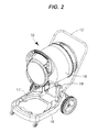
- Fig. 2 is a perspective view of the dolly seen in fig. 1a , with a wet/dry vacuum mounted on the dolly and tilted to a dumping position.
- Fig. 3 is an exploded view of the dolly seen in fig. 1 .
- Fig. 4 is a side view of the dolly seen in fig. 1 .
- Fig. 5 is a view along sectioning line 5-5 of fig. 4 ;
- Fig. 6 is a close-up view of the wheel lock seen on the left side of fig. 5 .
- Fig. 7 is a close-up view of the wheel lock seen on the right side of fig. 5 .
- Fig. 8 is a top view of the lever seen in figs. 5 and 6 .
- Fig. 9 is a schematic view of the cam surface of the lever seen in figs. 5 and 6 .
- Fig. 10 is a close-up view, corresponding to the view of fig. 7 , of an alternate embodiment of a wheel lock.
- Figs. 1-4 illustrate a dolly 10 that has a wheel lock that can be used with a cleaning device such as a wet/dry vacuum cleaner.
- the illustrated dolly has a tubular handle 12 connected to tubular uprights 13 and an optional basket 14.
- the dolly 10 also has a base 16, wheels 20, 24, and a pair of brakes.
- the base 16 is used to facilitate the transportation and the dumping of the contents of a tank on a cleaning device or similar apparatus.
- the base 16 is sized to receive the bottom of a wet/dry vacuum cleaner 18.
- the base 16 has a recess 17 that is sized to receive the vacuum cleaner. This recess 17 is designed to securely hold the cleaning device, aiding in resistance to lateral and vertical movements.
- the tank can be secured in the recess in a variety of ways known in the art, such as locking tabs, integrated clamps, or other such fastening methods.
- the base 16 also includes a pivot 19 on which the wet/dry vacuum cleaner 18 can be hinged.
- the pivot enables the tank on the vacuum cleaner 18 to be swung so that the contents of the tank can be dumped. Structure for accomplishing this is described in more detail in the U.S. patent publication no. 2007-0124885 A1 , the disclosure of which in hereby incorporated by reference.
- the pivot may be tubular or solid in design, and is positioned sideways on the base 16 above the rear wheels 24. The illustrate pivot is held in place by a pair of pan-head screws 25. It is positioned above the base to provide a stable axis around which the tank of the vacuum cleaner can be rotated, thus facilitating the safe removal of the contents in a rearward direction, toward the rear of the dolly 10.
- the wheels on the illustrated dolly 10 include a pair of front wheels 20 and a rear set of parallel wheels 24.
- the illustrated parallel wheels include a left rear wheel 24a and a right rear wheel 24b, both of which have large outer circumferences that make the dolly 10 more stable and easier to move, especially when the vacuum cleaner 18 is full of fluid.
- the wheels can be made of any conventional material, such as plastic.
- the illustrated rear wheels are 10-inch diameter, non-marring wheels. Although it is preferred for the parallel wheels to be set on a common axis, this may not always be necessary. In some cases it may be preferred to use the front wheels 20 (or the left-side wheels or the right-side wheels) as the parallel wheels, rather than the rear wheels 24.
- the parallel wheels 24 are mounted on a single axle 28 that extends along the common axis. Each wheel is held on the axle by a conventional push nut 29. Mounting the wheels on a single axis is merely optional. In some circumstances, the wheels might be mounted on separate mounting stems.
- the axis of the parallel wheels 24 is between 0 and 6 inches behind the pivot 19, so that when the cleaning device is on the dolly 10, the common axis of the parallel wheels is laterally between the pivot 19 and the center of gravity of the unit. This arrangement helps to prevent the dolly 10 from upsetting when the pivot 19 is used to dump the contents from the tank.
- the other wheels on the dolly 10 are generally not important.
- the other wheels are arranged to enable the dolly 10 to be easily turned.
- the two front wheels 20 are 3" diameter heavy-duty casters.
- Other arrangements are possible.
- a single front caster could be used, or a pair of wheels could be mounted on a shiftable axle.
- the illustrated dolly 10 has two separate brakes 30a, 30b, one for each of the parallel wheels 24.
- a separate brake 30 for each wheel may not be necessary.
- both parallel wheels are fixed to a common axle, in some circumstances it may be sufficient to provide a brake 30 on only one wheel, or on the axis itself.
- each illustrated brake 30 has a brake arm 32, a spring 34, and an operator-engagable lever 36. These elements will be discussed in more detail below.
- the brake arm 32 is made of a stiff material such as metal or plastic, and is strong enough to withstand forces associated with its use as a lever.
- the brake arm has two opposed ends. One end 38 of the illustrated brake arm is hinged to the base 16 so that it pivots between an engaged position and a disengaged position. In the engaged position (seen in fig. 6 ), part of the brake arm engages one of the parallel wheels, in this instance the left rear wheel 24a. In the disengaged position (seen in fig. 7 ), the brake arm 32 is disengaged from its associated wheel, in this instance the right rear wheel 24b.
- the other, distal end 42 of the brake arm 32 has a stop 40.
- the stop 40 is positioned to engage with and disengage from the adjacent wheel. In this example, it is positioned on the underside of the distal end 42 of the brake arm 32 and engages the outer circumference of the associated rear wheel 24, locking it against rotation. Other arrangements are possible.
- the stop (seen in fig. 7 ) is a piece of rubber or comparable material that is adhered or mechanically fastened to the end of the brake arm. A separate material is not always required; the stop could simply be an end surface of the brake arm.
- the spring 34 is used to bias the brake arm 32 to the disengaged position.
- the illustrated spring 34 is a metal helical coil compression spring, and is disposed on a pin 44 that extends through a slot 46 in the brake arm 32.
- the pin 44 seen in fig. 5 is a vertically-mounted 2.5" long hex-head machine screw that has a head 48 that sits in a well 50 formed on the opposite side of a hole 52 in the base I6. Other products could be used.
- An optional hex nut 54 can be mounted on the pin 44 to hold it in place.
- the spring 34 is positioned around a middle portion 56 of the pin 44 that projects above the hole 52.
- the spring can be positioned by simply lowering it over the upper end of the pin during the assembly process. Above the spring, the upper end of the pin passes through a slot 46 that is positioned laterally between the two ends 38, 42 of the brake arm 32.
- the spring 34 is thus trapped between the base 16 and the brake arm. In this arrangement, the spring biases the central portion of the brake arm away from the base. Because one end 38 of the brake arm is hinged to the base, this arrangement creates a third class lever that urges the distal end 42 of the brake arm away from the associated wheel 24 to the disengaged position.
- the brake arm 32 can be moved back from the disengaged position to the engaged position through the use of the operator-engagable lever 36.
- the illustrated lever is made of metal or sturdy plastic and is installed on the pin 44. In the illustrated example, the upper end of the pin is threaded and a cross-dowel nut 45 in the lever is turned onto those threads.
- the lever could also be attached in other ways, such as by a press fit or by a lock washer and nut.
- the lever is positioned so that it is hinged at a hinge axis 60 on the pin is at a distance "d" above the top surface of the brake arm 32 when the brake arm 32 is in the disengaged position.
- the lever can be attached in a variety of ways. As seen in fig. 7 , the illustrated lever 36 is arranged so that the cross-dawel nut 45 fits within a circular cylindrical recess formed in two arms 58 in the lever. A hollow area between the two arms enables the lever to pivot around the pin 44, moving between a locked position and an unlocked position. In the locked position (seen in fig. 6 ), the lever 36 presses the brake arm 32 into the engaged position. In the unlocked position (seen in fig. 7 ), the spring 34 is able to push the brake arm 32 into the disengaged position. This will be described in more detail below.
- a finger grip 61 is positioned outwardly from the hinge axis 60, and can be used to move the lever 36 from one position to another.
- the surface of the illustrated lever 36 is curved where it abuts the top surface of the brake arm 32.
- the distance between the hinge axis 60 and a first cam surface 62 on the lever 36 exceeds the distance "d", so that when the lever is moved so that the first cam surface 62 abuts the top surface of the brake arm 32 (as seen in fig. 6 ), the structure of the lever forces the top surface of the brake arm 32 downwards from the disengaged position, against the force of the spring 34.
- the distance between the hinge axis 60 and a second cam surface 64 on the lever 36 is less than or equal to the distance "d", so that when the lever 36 is moved so that the second cam surface 64 abuts the top surface of the brake arm 32 (the position seen in fig. 7 ), the force of the spring 34 can push the brake arm 32 toward the disengaged position.
- the cam surface on the lever 36 can be specifically shaped so that, once the lever is moved beyond a critical position, interaction between the lever and the brake arm 32 biases the lever toward the locked position.
- the cam surface of the lever 36 can be shaped with a profile 70 like that seen in fig. 9 . The chief characteristics of that profile can be seen by comparing it to a constant radius profile 72.
- the cam profile 70 has a critical point 74 that is farther from the hinge axis 60 than any other point on the cam surface.
- the angle ⁇ between a) a radial line that extends through that critical point and the hinge axis 60 and b) a line that is tangential to the cam surface at that critical point, is a right angle.
- the angle ⁇ between a radial line through the other point and a tangential line through that other point is less than 90 degrees.
- Positioning the critical point 74 between the cam positions 62 and 64 described above can provide advantages. With such an arrangement, when the lever 36 is moved from the unlocked position beyond the position where the critical point 74 abuts the brake arm 32, the lever 36 is biased further towards the locked position. This biasing would help to prevent the brake 30 from being accidentally unlocked. Conversely, once the lever is moved from the locked position beyond the position where the critical point abuts the brake arm, the lever would be biased further towards the unlocked position. This would help to assure that the brake 30 is fully disengaged.
- the cam surface on the lever 36 can also be provided with a flat section 90, as seen in fig. 10 .
- the illustrated flat section is the part of the lever that presses against the brake arm 32 when the lever is in the locked position. Providing a surface on the lever that rests flat against the top surface of the brake arm can provide a detent action when the lever is in the locked position, holding it in that position.
- the illustrated lever 36 provides a third class lever that can be used to press the brake arm 32 into the engaged position.
- the lever 36 might also be located in other positions, providing (for example) a first class lever or a second class lever.
Landscapes
- Engineering & Computer Science (AREA)
- Chemical & Material Sciences (AREA)
- Combustion & Propulsion (AREA)
- Transportation (AREA)
- Mechanical Engineering (AREA)
- Handcart (AREA)
Applications Claiming Priority (1)
| Application Number | Priority Date | Filing Date | Title |
|---|---|---|---|
| US11/782,106 US7758055B2 (en) | 2007-07-24 | 2007-07-24 | Dolly with wheel lock |
Publications (3)
| Publication Number | Publication Date |
|---|---|
| EP2019017A2 true EP2019017A2 (de) | 2009-01-28 |
| EP2019017A3 EP2019017A3 (de) | 2009-09-30 |
| EP2019017B1 EP2019017B1 (de) | 2012-10-24 |
Family
ID=40029057
Family Applications (1)
| Application Number | Title | Priority Date | Filing Date |
|---|---|---|---|
| EP08160465A Not-in-force EP2019017B1 (de) | 2007-07-24 | 2008-07-15 | Rollwagen mit Radsperre |
Country Status (6)
| Country | Link |
|---|---|
| US (1) | US7758055B2 (de) |
| EP (1) | EP2019017B1 (de) |
| CN (1) | CN101362464B (de) |
| AU (1) | AU2008202009B2 (de) |
| CA (1) | CA2630968C (de) |
| MX (1) | MX2008009471A (de) |
Families Citing this family (26)
| Publication number | Priority date | Publication date | Assignee | Title |
|---|---|---|---|---|
| US20090152826A1 (en) * | 2007-12-18 | 2009-06-18 | Jose Freitas Silva | Cargo cart with hitch for wheeled mobility device |
| US20090302563A1 (en) | 2008-06-09 | 2009-12-10 | Thibault Richard R | Painters wheeled caddy |
| DE202009004554U1 (de) * | 2009-04-02 | 2009-07-23 | Airbus Deutschland Gmbh | Platzsparend aufbewahrbarer Transportwagen zur Bestückung einer Flugzeugbordküche |
| US8707497B2 (en) * | 2009-11-11 | 2014-04-29 | Shop Vac Corporation | Combination vacuum cleaner, dolly, and mounting bracket |
| US9266548B1 (en) * | 2010-05-18 | 2016-02-23 | Worldwide Integrated Resources, Inc. | Combination trash can dolly and mop bucket and combination janitorial cart and mop bucket |
| US8256778B1 (en) * | 2010-05-18 | 2012-09-04 | Worldwide Integrated Resources, Inc. | Combination trash can dolly and mop bucket |
| USD640287S1 (en) * | 2011-02-07 | 2011-06-21 | Dubois Ernest M | Portable lawn debris bucket |
| US20120246866A1 (en) * | 2011-03-28 | 2012-10-04 | Emerson Electric Co. | Support System Adjustable by Like Motion and Method of Use |
| US8636291B1 (en) * | 2011-04-22 | 2014-01-28 | Clint Adam Kay | Tool bucket transport device |
| CN102649442B (zh) * | 2012-05-09 | 2014-02-12 | 风神轮胎股份有限公司 | 成品工程胎翻转运输专用车 |
| USD729987S1 (en) * | 2012-10-26 | 2015-05-19 | Hans Joachim Holm | Feeder and waterer |
| US9150234B2 (en) * | 2013-03-15 | 2015-10-06 | San Jamar, Inc. | Tote transport |
| USD729988S1 (en) * | 2013-04-23 | 2015-05-19 | Hans Joachim Holm | Feeder and waterer |
| USD777396S1 (en) * | 2015-06-15 | 2017-01-24 | Deneen Milton | Multipurpose mobile caddy |
| CA3033261C (en) | 2016-09-22 | 2021-04-13 | Shop Vac Corporation | Vacuum cleaner handle mount assembly |
| WO2019028041A1 (en) | 2017-07-31 | 2019-02-07 | Milwaukee Electric Tool Corporation | Storage device system |
| CN111615481B (zh) * | 2017-12-20 | 2022-11-04 | 凯特尔塑料有限公司 | 台车及其机械制动系统 |
| CN111867785A (zh) | 2018-01-24 | 2020-10-30 | 米沃奇电动工具公司 | 工具储存装置 |
| IL257294A (en) | 2018-02-01 | 2018-03-29 | Milwaukee Electric Tool Corp | Coupleable crate |
| KR101899755B1 (ko) * | 2018-03-21 | 2018-09-17 | 여신동 | 바퀴잠금 및 해제가 용이한 카트 |
| CN112236065A (zh) * | 2018-06-04 | 2021-01-15 | 米沃奇电动工具公司 | 模块化真空系统 |
| IL260225A (en) | 2018-06-24 | 2018-07-31 | Keter Plastic Ltd | pushcart |
| US10850920B1 (en) * | 2019-09-04 | 2020-12-01 | Prairie View Industries, Inc. | Wheeled platform and methods of making and using the same |
| IL269564B2 (en) | 2019-09-23 | 2023-11-01 | Keter Home & Garden Products Ltd | Sawhorse |
| US12421026B2 (en) | 2021-09-14 | 2025-09-23 | Cfs Brands, Llc | Trash bin dolly system |
| CN115339497B (zh) * | 2022-09-22 | 2023-07-11 | 瑞昌市华林蜂业开发有限公司 | 一种便于装箱的蜂蜜桶运输装置 |
Citations (1)
| Publication number | Priority date | Publication date | Assignee | Title |
|---|---|---|---|---|
| US20070124885A1 (en) | 2005-12-05 | 2007-06-07 | Shop Vac Corporation | Cleaning device with pivoting tank |
Family Cites Families (13)
| Publication number | Priority date | Publication date | Assignee | Title |
|---|---|---|---|---|
| US2262433A (en) * | 1939-05-16 | 1941-11-11 | Safway Steel Scaffolds Co | Caster |
| US3117653A (en) | 1961-12-18 | 1964-01-14 | Jacob J Altherr | Brake mechanism for telescoping carts |
| DE1939966U (de) | 1966-03-17 | 1966-06-02 | Albert Schulte & Soehne K G | Feststell- und bremsvorrichtung fuer lenkrollen. |
| US3930630A (en) * | 1974-08-05 | 1976-01-06 | Advance Machine Company | Vacuum cleaner support apparatus |
| US4349937A (en) * | 1980-07-11 | 1982-09-21 | Stewart-Warner Corporation | Caster assembly with swivel lock and brake |
| EP0204040A1 (de) * | 1985-06-05 | 1986-12-10 | Quadra Wheelchairs, Inc. | Bremsvorrichtung für Rollstühle |
| US5042622A (en) * | 1990-05-22 | 1991-08-27 | Leonard Smith | Shopping cart foot brake assembly |
| US5497856A (en) * | 1994-08-31 | 1996-03-12 | Colson Caster Corporation | Locking caster brake assembly |
| US5784757A (en) | 1996-01-11 | 1998-07-28 | Royal Appliance Mfg. Co. | Vacuum cleaner hose assembly |
| US6102167A (en) * | 1998-11-05 | 2000-08-15 | Chiu; Ping-Jan | Brake device for a stroller |
| US6381804B1 (en) | 2000-09-29 | 2002-05-07 | Oreck Holdings, Llc | Apparatus for conducting air into bags of vacuum cleaners |
| CN2543482Y (zh) * | 2002-01-29 | 2003-04-09 | 郭盈成 | 推车式的清洁用具结构 |
| WO2004006820A2 (en) | 2002-07-17 | 2004-01-22 | Lawrence-Nelson, Llc | Wheelchair wheel immobilizer |
-
2007
- 2007-07-24 US US11/782,106 patent/US7758055B2/en active Active
-
2008
- 2008-05-06 AU AU2008202009A patent/AU2008202009B2/en not_active Ceased
- 2008-05-08 CA CA2630968A patent/CA2630968C/en not_active Expired - Fee Related
- 2008-06-03 CN CN2008100859293A patent/CN101362464B/zh not_active Expired - Fee Related
- 2008-07-15 EP EP08160465A patent/EP2019017B1/de not_active Not-in-force
- 2008-07-23 MX MX2008009471A patent/MX2008009471A/es active IP Right Grant
Patent Citations (1)
| Publication number | Priority date | Publication date | Assignee | Title |
|---|---|---|---|---|
| US20070124885A1 (en) | 2005-12-05 | 2007-06-07 | Shop Vac Corporation | Cleaning device with pivoting tank |
Also Published As
| Publication number | Publication date |
|---|---|
| US7758055B2 (en) | 2010-07-20 |
| EP2019017A3 (de) | 2009-09-30 |
| CN101362464B (zh) | 2012-07-04 |
| AU2008202009B2 (en) | 2012-03-15 |
| CA2630968C (en) | 2015-03-17 |
| MX2008009471A (es) | 2009-03-05 |
| CA2630968A1 (en) | 2009-01-24 |
| CN101362464A (zh) | 2009-02-11 |
| AU2008202009A1 (en) | 2009-02-12 |
| EP2019017B1 (de) | 2012-10-24 |
| US20090026721A1 (en) | 2009-01-29 |
Similar Documents
| Publication | Publication Date | Title |
|---|---|---|
| EP2019017B1 (de) | Rollwagen mit Radsperre | |
| US6308967B1 (en) | Dual hand truck | |
| US6367494B1 (en) | Movable sunshade base | |
| US3930630A (en) | Vacuum cleaner support apparatus | |
| US4640521A (en) | Dolly with tank latch | |
| US8544874B2 (en) | Transport device frame assembly | |
| US5170529A (en) | Foot operable cart wheel lock | |
| US6446989B1 (en) | Pin drive wheelbarrow | |
| US6508479B1 (en) | Wagon with wheel braking device | |
| US7740251B2 (en) | Hand truck for appliances | |
| AU2006202439A1 (en) | I.V. support stand and clamp apparatus | |
| US4902187A (en) | Drum dolly attachment apparatus | |
| US20100264187A1 (en) | Removable tire carrier | |
| US3044577A (en) | Shopping cart brake | |
| US7883068B2 (en) | Actuatable holding system | |
| US7699576B2 (en) | Tire lifting and mounting tool | |
| US2197587A (en) | Hand truck | |
| US2631329A (en) | Caster of the disappearing type | |
| HK1124294A (en) | Dolly with wheel lock | |
| WO2005056085A1 (en) | I.v. support stand and components therefor | |
| US20110193039A1 (en) | Motorcycle lift dolly | |
| CN223999273U (zh) | 一种平底中控刹车脚轮 | |
| CA2447109C (en) | Hand cart unloading system with rotatable handle | |
| EP2010400B1 (de) | Sperr-/freigabevorrichtung für eine verstellbare radgabel und mit der vorrichtung ausgestattete krankentrage | |
| EP4348629A1 (de) | Warnkegel und teilesatz |
Legal Events
| Date | Code | Title | Description |
|---|---|---|---|
| PUAI | Public reference made under article 153(3) epc to a published international application that has entered the european phase |
Free format text: ORIGINAL CODE: 0009012 |
|
| AK | Designated contracting states |
Kind code of ref document: A2 Designated state(s): AT BE BG CH CY CZ DE DK EE ES FI FR GB GR HR HU IE IS IT LI LT LU LV MC MT NL NO PL PT RO SE SI SK TR |
|
| AX | Request for extension of the european patent |
Extension state: AL BA MK RS |
|
| PUAL | Search report despatched |
Free format text: ORIGINAL CODE: 0009013 |
|
| AK | Designated contracting states |
Kind code of ref document: A3 Designated state(s): AT BE BG CH CY CZ DE DK EE ES FI FR GB GR HR HU IE IS IT LI LT LU LV MC MT NL NO PL PT RO SE SI SK TR |
|
| AX | Request for extension of the european patent |
Extension state: AL BA MK RS |
|
| 17P | Request for examination filed |
Effective date: 20091229 |
|
| AKX | Designation fees paid |
Designated state(s): CH DE FR GB IE IT LI |
|
| 17Q | First examination report despatched |
Effective date: 20100722 |
|
| GRAP | Despatch of communication of intention to grant a patent |
Free format text: ORIGINAL CODE: EPIDOSNIGR1 |
|
| GRAS | Grant fee paid |
Free format text: ORIGINAL CODE: EPIDOSNIGR3 |
|
| GRAA | (expected) grant |
Free format text: ORIGINAL CODE: 0009210 |
|
| AK | Designated contracting states |
Kind code of ref document: B1 Designated state(s): CH DE FR GB IE IT LI |
|
| REG | Reference to a national code |
Ref country code: GB Ref legal event code: FG4D |
|
| REG | Reference to a national code |
Ref country code: CH Ref legal event code: EP |
|
| REG | Reference to a national code |
Ref country code: IE Ref legal event code: FG4D |
|
| REG | Reference to a national code |
Ref country code: DE Ref legal event code: R096 Ref document number: 602008019565 Country of ref document: DE Effective date: 20121220 |
|
| REG | Reference to a national code |
Ref country code: CH Ref legal event code: NV Representative=s name: ISLER AND PEDRAZZINI AG, CH |
|
| PLBE | No opposition filed within time limit |
Free format text: ORIGINAL CODE: 0009261 |
|
| STAA | Information on the status of an ep patent application or granted ep patent |
Free format text: STATUS: NO OPPOSITION FILED WITHIN TIME LIMIT |
|
| 26N | No opposition filed |
Effective date: 20130725 |
|
| REG | Reference to a national code |
Ref country code: DE Ref legal event code: R097 Ref document number: 602008019565 Country of ref document: DE Effective date: 20130725 |
|
| REG | Reference to a national code |
Ref country code: FR Ref legal event code: PLFP Year of fee payment: 8 |
|
| PGFP | Annual fee paid to national office [announced via postgrant information from national office to epo] |
Ref country code: IE Payment date: 20150709 Year of fee payment: 8 Ref country code: CH Payment date: 20150713 Year of fee payment: 8 |
|
| PGFP | Annual fee paid to national office [announced via postgrant information from national office to epo] |
Ref country code: IT Payment date: 20150727 Year of fee payment: 8 |
|
| REG | Reference to a national code |
Ref country code: FR Ref legal event code: PLFP Year of fee payment: 9 |
|
| REG | Reference to a national code |
Ref country code: CH Ref legal event code: PL |
|
| PG25 | Lapsed in a contracting state [announced via postgrant information from national office to epo] |
Ref country code: LI Free format text: LAPSE BECAUSE OF NON-PAYMENT OF DUE FEES Effective date: 20160731 Ref country code: CH Free format text: LAPSE BECAUSE OF NON-PAYMENT OF DUE FEES Effective date: 20160731 |
|
| REG | Reference to a national code |
Ref country code: IE Ref legal event code: MM4A |
|
| REG | Reference to a national code |
Ref country code: FR Ref legal event code: PLFP Year of fee payment: 10 |
|
| PG25 | Lapsed in a contracting state [announced via postgrant information from national office to epo] |
Ref country code: IE Free format text: LAPSE BECAUSE OF NON-PAYMENT OF DUE FEES Effective date: 20160715 |
|
| PGFP | Annual fee paid to national office [announced via postgrant information from national office to epo] |
Ref country code: FR Payment date: 20170613 Year of fee payment: 10 |
|
| PG25 | Lapsed in a contracting state [announced via postgrant information from national office to epo] |
Ref country code: IT Free format text: LAPSE BECAUSE OF NON-PAYMENT OF DUE FEES Effective date: 20160715 |
|
| PGFP | Annual fee paid to national office [announced via postgrant information from national office to epo] |
Ref country code: DE Payment date: 20170711 Year of fee payment: 10 Ref country code: GB Payment date: 20170712 Year of fee payment: 10 |
|
| REG | Reference to a national code |
Ref country code: DE Ref legal event code: R119 Ref document number: 602008019565 Country of ref document: DE |
|
| GBPC | Gb: european patent ceased through non-payment of renewal fee |
Effective date: 20180715 |
|
| PG25 | Lapsed in a contracting state [announced via postgrant information from national office to epo] |
Ref country code: DE Free format text: LAPSE BECAUSE OF NON-PAYMENT OF DUE FEES Effective date: 20190201 Ref country code: FR Free format text: LAPSE BECAUSE OF NON-PAYMENT OF DUE FEES Effective date: 20180731 Ref country code: GB Free format text: LAPSE BECAUSE OF NON-PAYMENT OF DUE FEES Effective date: 20180715 |