EP2018965A1 - Image recording apparatus - Google Patents
Image recording apparatus Download PDFInfo
- Publication number
- EP2018965A1 EP2018965A1 EP08013484A EP08013484A EP2018965A1 EP 2018965 A1 EP2018965 A1 EP 2018965A1 EP 08013484 A EP08013484 A EP 08013484A EP 08013484 A EP08013484 A EP 08013484A EP 2018965 A1 EP2018965 A1 EP 2018965A1
- Authority
- EP
- European Patent Office
- Prior art keywords
- head
- ink
- liquid ejection
- wipers
- ejection
- Prior art date
- Legal status (The legal status is an assumption and is not a legal conclusion. Google has not performed a legal analysis and makes no representation as to the accuracy of the status listed.)
- Granted
Links
Images





Classifications
-
- B—PERFORMING OPERATIONS; TRANSPORTING
- B41—PRINTING; LINING MACHINES; TYPEWRITERS; STAMPS
- B41J—TYPEWRITERS; SELECTIVE PRINTING MECHANISMS, i.e. MECHANISMS PRINTING OTHERWISE THAN FROM A FORME; CORRECTION OF TYPOGRAPHICAL ERRORS
- B41J2/00—Typewriters or selective printing mechanisms characterised by the printing or marking process for which they are designed
- B41J2/005—Typewriters or selective printing mechanisms characterised by the printing or marking process for which they are designed characterised by bringing liquid or particles selectively into contact with a printing material
- B41J2/01—Ink jet
- B41J2/135—Nozzles
- B41J2/165—Prevention or detection of nozzle clogging, e.g. cleaning, capping or moistening for nozzles
- B41J2/16585—Prevention or detection of nozzle clogging, e.g. cleaning, capping or moistening for nozzles for paper-width or non-reciprocating print heads
-
- B—PERFORMING OPERATIONS; TRANSPORTING
- B41—PRINTING; LINING MACHINES; TYPEWRITERS; STAMPS
- B41J—TYPEWRITERS; SELECTIVE PRINTING MECHANISMS, i.e. MECHANISMS PRINTING OTHERWISE THAN FROM A FORME; CORRECTION OF TYPOGRAPHICAL ERRORS
- B41J2/00—Typewriters or selective printing mechanisms characterised by the printing or marking process for which they are designed
- B41J2/005—Typewriters or selective printing mechanisms characterised by the printing or marking process for which they are designed characterised by bringing liquid or particles selectively into contact with a printing material
- B41J2/01—Ink jet
- B41J2/135—Nozzles
- B41J2/145—Arrangement thereof
- B41J2/155—Arrangement thereof for line printing
Definitions
- the present invention relates to an image recording apparatus having a liquid ejection head which ejects liquid.
- Japanese Unexamined Patent Publication No. 2005-132025 discloses an ink-jet printer including four ink-jet heads and a maintenance unit.
- the four ink-jet heads are arranged side by side in a paper conveyance direction.
- the maintenance unit performs maintenance on the four ink-jet heads.
- the maintenance unit has a support member, a blade, a wipe roller, an ink absorber, and four caps.
- the support member is horizontally movable along a paper conveyance direction.
- the blade, the wipe roller, the ink absorber, and the four caps are mounted on the support member.
- each cap When the maintenance unit is in a purge position, each cap covers a nozzle face and a purge operation is performed so that ink is ejected from nozzles toward the cap. Then, each cap gets separated from the nozzle face. While the maintenance unit is moving to a withdrawal position, the ink absorber, the wipe roller, and the blade sequentially get opposed to the nozzle faces so that ink is absorbed and wiped off by the respective members. In this way, maintenance is performed on the four ink-jet heads.
- the withdrawal position of the maintenance unit is located downstream of the ink-jet heads in the paper conveyance direction, which increases a size of the ink-jet printer with respect to the paper conveyance direction.
- An object of the present invention is to provide an image recording apparatus which can be downsized even if they have a plurality of liquid ejection heads.
- an image recording apparatus comprising a plurality of liquid ejection heads, a recording medium conveyance mechanism, a plurality of wipers, and a movement mechanism.
- the plurality of liquid ejection heads respectively have ejection faces which are arranged in such a manner that the ejection faces form two rows extending in one direction and in addition two of the ejection faces included in different rows do not overlap each other along a direction perpendicular to the one direction with respect to an in-plane direction of the ejection faces.
- the plurality of liquid ejection heads are divided into a plurality of head groups each including two of the liquid ejection heads corresponding to the different rows.
- the recording medium conveyance mechanism conveys a recording medium in the one direction while making the recording medium opposed to the ejection faces.
- the plurality of wipers wipe the ejection faces of the liquid ejection heads.
- the movement mechanism moves two of the wipers for wiping two ejection faces of the two liquid ejection heads belonging to each head group, in opposite directions with respect to the perpendicular direction while keeping the two wipers in contact with the ejection faces.
- the wiper associated with one of the liquid ejection heads belonging to each head group is positioned so as to overlap the one liquid ejection head along the perpendicular direction and in addition overlap the other of the liquid ejection heads along the one direction, while, when in the wiper withdrawal position, the wiper associated with the other liquid ejection head is positioned so as to overlap the other liquid ejection head along the perpendicular direction and in addition overlap the one liquid ejection head along the one direction.
- ejection faces of the plurality of liquid ejection heads are arranged in two rows extending along one direction, in such a manner that two ejection faces belonging to different rows do not overlap each other along a direction perpendicular to the one direction.
- a free space appears in a region neighboring each liquid ejection head with respect to the perpendicular direction.
- a plurality of wipers associated with the respective liquid ejection heads are withdrawn into the space. Withdrawing the wipers into the free space in this way makes it unnecessary to provide another space which is special for the wipers to be positioned therein. Therefore, downsizing of the image recording apparatus can be realized.
- each of the plurality of head groups is made up of two of the liquid ejection heads which eject liquid of the same color, and the movement mechanism selectively moves the plurality of wipers in units of the two wipers associated with the head group.
- the image recording apparatus further comprises a movement control means which controls the movement mechanism in such a manner that the two wipers associated with, among the plurality of head groups, the selected head group wipe two ejection faces in the head group.
- the movement mechanism includes a plurality of belts each of which is coupled with the two wipers associated with the head group and travels along the perpendicular direction to thereby move the two wipers in the opposite directions, and a plurality of switching means each of which can be switched between a state of transmitting power from a drive source to the belt and a state of transmitting power from the drive source to the belt.
- the movement control means switches at least one of the switching means into the state of transmitting power from the drive source to the belt.
- the movement control means switches all the switching means into the state of transmitting power from the drive source to the belt.
- the movement control means can switch all the switching means so as to transmit power from the drive source to the belt. Therefore, the ejection faces in all the head groups can be wiped by the wipers. This can shorten a time required for wiping all the ejection faces by the wipers.
- each of the plurality of belts is disposed so as to, in a plan view, enclose the two liquid ejection heads belonging to the head group and the two wipers associated with the head group. As a result, a space formed between the head groups can be made small.
- each of the plurality of belts is disposed between the two liquid ejection heads belonging to the head group, in such a manner that portions of the belt extending in the perpendicular direction are opposed to each other with respect to a vertical direction.
- a space formed between the head groups can be made small, because the portions of the belt extending in the perpendicular direction are opposed to each other with respect to the vertical direction.
- a length of the belt can be made relatively short, which can reduce a load placed on the drive source.
- the image recording apparatus further comprises a plurality of caps which cover the ejection faces by being in contact with the ejection faces.
- Each belt is coupled with two of the caps which are associated with the two liquid ejection heads belonging to the head group, and travels along the perpendicular direction so that the two caps move in the opposite directions along the perpendicular direction between a capping position opposed to the ejection face and a cap withdrawal position not opposed to the ejection face.
- the plurality of caps can also be selected and moved in units of two caps associated with the head group.
- the cap associated with the one liquid ejection head when in the cap withdrawal position, is positioned so as to overlap the one liquid ejection head along the perpendicular direction and in addition overlap the other liquid ejection head along the one direction, while, when in the cap withdrawal position, the cap associated with the other liquid ejection head is positioned so as to overlap the other liquid ejection head along the perpendicular direction and in addition overlap the one liquid ejection head along the one direction.
- the plurality of caps associated with the respective liquid ejection heads are positioned in the free space neighboring each liquid ejection head with respect to the perpendicular direction. This can further reduce the size of the liquid ejection apparatus.
- the cap associated with the liquid ejection head is located in such a position that the wiper associated with the liquid ejection head is sandwiched between the cap and the liquid ejection head with respect to the perpendicular direction. This can still further reduce the size of the liquid ejection apparatus.
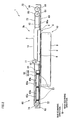
- FIG. 1 is a plan view of an essential part of an ink-jet printer according to a first embodiment of the present invention.
- FIG. 2 is a sectional view as taken along line II-II illustrated in FIG. 1 .
- FIG. 3 shows four head groups illustrated in FIG. 1 , as seen from a bottom side thereof.
- an ink-jet printer 1 which is an image recording apparatus according to a first embodiment of the present invention, is a color ink-jet printer of line type including four head groups 3a, 3b, 3c, and 3d each of which is made up of two ink-jet heads 2 or liquid ejection heads.
- the ink-jet printer 1 has a paper feed unit (not shown) and a paper discharge unit (not shown) at upper and lower parts of FIG. 1 , respectively.
- a paper conveyance mechanism 10 which is a recording medium conveyance mechanism is provided between the paper feed unit and the paper discharge unit, at a position opposed to the four head groups 3a, 3b, 3c, and 3d.
- the paper conveyance mechanism 10 conveys a paper as a recording medium to a position opposed to ink ejection faces 4 which are ejection faces of the eight ink-jet heads 2.
- the paper conveyance mechanism 10 has a pair of belt rollers 6 and 7 which are disposed so as to sandwich the four head groups 3a, 3b, 3c, and 3d with respect to the sub scanning direction (i.e., an up-and-down direction in FIG.
- a conveyor motor 97 applies driving force to the belt roller 7 which is thereby rotated in a predetermined direction.
- the conveyor belt 8 travels so as to convey the paper in a paper conveyance direction A (i.e., in a direction from up to down in FIG. 1 ).
- the conveyor belt 8 has a two-layer structure made up of a base material and urethane rubber.
- An outer surface of the conveyor belt 8, that is, a conveyor face 9 has adhesiveness. A paper fed out from the paper feed unit is maintained due to the adhesiveness of the conveyor face 9, and in this condition conveyed in the conveyance direction A.
- Each ink-jet head 2 has a rectangular parallelepiped shape elongated in a main scanning direction (which is a direction perpendicular to the paper conveyance direction A: a perpendicular direction), as shown in FIGs. 1 and 2 .
- Each ink-jet head 2 has a head main body 5 at its lower end.
- a reservoir unit which temporarily stores ink therein is fixed to an upper face of the head main body 5.
- the reservoir unit is partially covered with a cover 14.
- a tube joint 11 is connected to a left end of the reservoir unit. Ink supplied through the tube joint 11 is stored in an ink reservoir which is formed within the reservoir unit.
- the reservoir unit is longer than the head main body 5 with respect to the main scanning direction.
- Portions 12 of the reservoir unit extend out on both sides of the reservoir unit with respect to the main scanning direction.
- the portions 12 serve as a fixing portion to be fixed to an elevation frame (not shown) which is provided for every reservoir unit.
- Each ink-jet head 2 is fixed to the elevation frame via the fixing portion.
- the elevation frame can be moved up and down by a head elevation mechanism 98 (see FIG. 4 ).
- the eight ink-jet heads 2 are disposed in a printing position (i.e., a position of the ink-jet head 2 shown in FIG. 2 ).
- a printing position i.e., a position of the ink-jet head 2 shown in FIG. 2 .
- each ink ejection face 4 and the conveyor face 9 of the conveyor belt 8 extend in parallel with each other and at a predetermined interval therebetween.
- the head elevation mechanism 98 moves up the elevation frame to which an ink-jet head 2 to be subjected to the maintenance operation is fixed.
- small-diameter nozzles 4a which eject ink
- an ink ejection region 4b which is formed by a collection of the nozzles 4a
- an outside region 4c which surrounds the ink ejection region 4b are provided on a bottom face of the head main body 5, that is, on the ink ejection face 4 of the ink-jet head 2.
- the eight ink-jet heads 2 are arranged in a zigzag pattern in such a manner that the ink ejection faces 4 form two rows each including four ink ejection faces 4 which are arranged side by side along the sub scanning direction and in addition the ink ejection faces 4 included in different rows do not overlap each other with respect to the main scanning direction.
- the eight ink-jet heads 2 are divided into four head groups 3a, 3b, 3c, and 3d each of which includes two ink-jet heads 2. Ink ejection faces 4 of the two ink-jet heads 2 neighbor each other with respect to the sub scanning direction and belong to different rows.
- the four head groups 3a, 3b, 3c, and 3d are arranged side by side along the sub scanning direction, so as to arrange the eight ink-jet heads 2 in a zigzag pattern with respect to the sub scanning direction.
- Two ink-jet heads 2 included in each of the head groups 3a, 3b, 3c, and 3d have their ink ejection faces 4 overlap each other in the sub scanning direction, so that print regions (i.e., ink ejection regions 4b) for making printing on a paper continue in the main scanning direction. More specifically, two ink-jet heads 2 included in the same head group are arranged in such a manner that an interval in the main scanning direction between neighboring nozzles 4a in an ink ejection region 4b of one ink-jet head 2 is the same as an interval in the main scanning direction between an innermost (i.e., leftmost in FIG.
- Each of the other head groups 3b, 3c, and 3d includes two ink-jet heads 2 arranged in the same manner as in the head group 3a.
- the eight ink-jet heads 2 eject ink of four different colors (magenta, yellow, cyan, and black), each color corresponds to each of the head groups 3a, 3b, 3c, and 3d. That is, two ink-jet heads 2 belonging to the same head group, neighboring each other in the sub scanning direction, and included in different rows eject ink of the same color.
- the maintenance unit 60 which performs maintenance on the ink-jet heads 2 will be described.
- the maintenance unit 60 has four caps 61 and four wipers 63, four caps 62 and four wipers 64, a movement mechanism 70, and a tray 69.
- the four caps 61 and four wipers 63 are associated with four ink-jet heads 2 which belong to the respective head groups 3a, 3b, 3c, and 3d arranged side by side along the sub scanning direction and are included in one (left one in FIG. 1 ) of the rows.
- the four caps 62 and four wipers 64 are associated with four ink-jet heads 2 which belong to the respective head groups 3a, 3b, 3c, and 3d arranged side by side along the sub scanning direction and are included in one (right one in FIG. 1 ) of the rows.
- the movement mechanism 70 moves, on a head group basis, the eight caps 61 and 62 and the eight wipers 63 and 64 in the main scanning direction.
- the tray 69 contains therein the eight caps 61 and 62, the eight wipers 63 and 64, and the movement mechanism 70.
- the tray 69 has a pass through 68a which extends through the tray 69 in a vertical direction.
- the pass through 68a is at a position opposed to each ink-jet head 2.
- the pass through 68a has a rectangular shape in a plan view, and has such a size that each of the eight ink ejection faces 4 of the respective ink-jet heads 2 can entirely be opposed to the conveyor face 9.
- the caps 61 and 62 have the same shape and the same size, and each of them is made up of a base material 65 and an annular protrusion 66.
- a shape of the base material 65 is similar to but slightly larger than the ink ejection region 4b.
- the annular protrusion 66 stands at a periphery of the base material 65. This structure allows the caps 61 and 62 to cover the ink ejection regions 4b with distal ends of the annular protrusions 66 being in contact with the outside regions 4c of the ink ejection faces 4. Thereby, drying of ink existing within the nozzles 4a can be suppressed.
- Two recesses 65a which open upward in the vertical direction are formed in the base material 65.
- the two recesses 65a are disposed side by side along the main scanning direction.
- a through hole 65b is formed at a bottom of the recess 65a. Since the through holes 65b are formed, ink ejected into the caps 61, 62 in a purge operation and collected within the recess 65a can be discarded through the through holes 65b into a not-shown waste ink reservoir.
- each of the caps 61, 62 is supported from below by three springs 67. Since each of the caps 61, 62 is supported by the three springs 67, impact caused when the annular protrusion 66 comes into contact with the ink ejection face 4 can be softened, so that the ink ejection face 4 is not easily damaged by the annular protrusion 66.
- the maintenance unit 60 also has a cap level adjusting mechanism 99 (see FIG. 4 ) which moves down the caps 61, 62 when the wipers 63, 64 wipe the ink ejection faces 4. As the cap level adjusting mechanism 99 moves down the caps 61, 62, distal ends of the wipers 63, 64 come higher than the caps 61, 62, and the caps 61, 62 no longer come into contact with the ink ejection faces 4.
- each of the wipers 63, 64 is disposed between a corresponding ink-jet head 2 and a cap 61, 62 associated with this ink-jet head 2.
- a length of extension of the wiper 63, 64 is substantially equal to a width of the ink ejection face 4 of the corresponding ink-jet head 2 with respect to the sub scanning direction.
- the wipers 63, 64 are made of an elastic material such as rubber.
- the wipers 63, 64 stand on later-described support plates 71, 72 which support the caps 61, 62 via the springs 67. In a case where the caps 61, 62 are not moved down by the cap level adjusting mechanism 99, the distal ends of the wipers 63, 64 are substantially at the same level as the base materials of the caps 61, 62.
- the wiper 63 for the head group 3a When disposed in a withdrawal position not opposed to the ink ejection face 4 (as shown in FIG. 1 ), the wiper 63 for the head group 3a locates in a position overlapping the corresponding left-side ink-jet head 2 in FIG. 1 in the main scanning direction and overlapping the right-side ink-jet head 2 in FIG. 1 in the sub scanning direction.
- the wiper 64 for the head group 3a locates in a position overlapping the corresponding right-side ink-jet head 2 in FIG. 1 in the main scanning direction and overlapping the left-side ink-jet head 2 in FIG. 1 in the sub scanning direction.
- the wipers 63, 64 for the head groups 3b, 3c, and 3d are positioned in the same manner as the wipers 63, 64 for the head group 3a are.
- the withdrawal position is equivalent to a wiper withdrawal position and a cap withdrawal position of the present invention.
- the movement mechanism 70 has two shafts 90 and 93, four shafts 81, four belt rollers 74, four belt rollers 75, four belts 73, eight support plates 71 and 72, and a power transmission mechanism 80.
- the two shafts 90 and 93, and the four shafts 81 extend in the sub scanning direction, and are supported rotatably about an axis thereof.
- the four belt rollers 74 are provided for the four shafts 81, respectively.
- the four belt rollers 75 are provided on the shaft 93.
- Each of the four belts 73 spans the belt rollers 74 and 75.
- the eight support plates 71 and 72 are coupled with the four belts 73, respectively.
- the power transmission mechanism 80 transmits rotational power to each belt roller 74.
- the four support plates 71 support the caps 61 and wipers 63 associated with, among the ink-jet heads of the head groups 3a, 3b, 3c, and 3d, the ink-jet heads 2 included in one (left one in FIG. 1 ) of the rows extending in the sub scanning direction.
- the four support plates 71 are coupled with portions of the belts 73 extending in the main scanning direction.
- the cap 61 and the wiper 63 are positioned in such a manner that, in a plan view, they overlap the corresponding ink-jet head 2 in the main scanning direction and also overlap the other ink-jet head 2 belonging to the same head group as the corresponding ink-jet head 2 in the sub scanning direction.
- the four support plates 72 support the caps 62 and wipers 64 associated with, among the ink-jet heads of the head groups 3a, 3b, 3c, and 3d, the ink-jet heads 2 included in the other (right one in FIG. 1 ) of the rows extending in the sub scanning direction.
- the four support plates 72 are coupled with portions of the belts 73 extending in the main scanning direction.
- the cap 62 and the wiper 64 are positioned in such a manner that, in a plan view, they overlap the corresponding ink-jet head 2 in the main scanning direction and also overlap the other ink-jet head 2 belonging to the same head group as the corresponding ink-jet head 2 in the sub scanning direction.
- the eight support plates 71 and 72 are arranged in a zigzag pattern inverse to the zigzag arrangement pattern of the eight ink-jet heads 2.
- the four belt rollers 75 are mounted on the shaft 93, at positions overlapping the respective head groups 3a, 3b, 3c, and 3d with respect to the main scanning direction, with their diameters extending in the vertical direction.
- the four belt rollers 75 are supported rotatably in clockwise and counterclockwise directions in FIG. 2 .
- the four belt rollers 74 are mounted on the four shafts 81, at positions overlapping the respective head groups 3a, 3b, 3c, and 3d with respect to the main scanning direction, with their diameters extending in the vertical direction.
- the four belt rollers 74 are fixed rotatably in clockwise and counterclockwise directions in FIG. 2 .
- Each of the four belts 73 is wound on a pair of belt rollers 74 and 75 to be stretched between them and, with respect to the sub scanning direction, positioned between two of the ink-jet heads 2 belonging to the head groups 3a, 3b, 3c, and 3d. Portions of the belt 73 extending in the main scanning direction are opposed to each other with respect to the vertical direction.
- the belt 73 of this embodiment is a rubber-made flat belt having a very narrow width. However, a rubber belt having a circular section, or a metal-made wire may be adopted for the belt 73. In short, any member may be adopted as long as it functions as a belt.
- the power transmission mechanism 80 has a gear 92, four gears 91, four gears 85, and clutches 84.
- the gear 92 is fixed to one end (upper end in FIG. 1 ) of the shaft 90 so as to be rotatable with the shaft 90 about an axis of the shaft 90.
- the four gears 91 are fixed to the shaft 90 at positions along the sub scanning direction which correspond to the respective heads 3a, 3b, 3c, and 3d.
- the four gears 91 are rotatable with the shaft 90 about the axis of the shaft 90.
- the four gears 85 are engaged with the four gears 91 to thereby rotate with the four gears 91.
- the clutches 84 are four switching means each disposed between each of the four gears 85 and each of the four shafts 81.
- the clutch 84 has an input shaft 84a fixed to the gears 85, and an output shaft 84b fixed to the shafts 81.
- the clutch 84 has such a structure that the input shaft 84a and the output shaft 84b are electromagnetically coupled with each other so that power is transmitted from the input shaft 84a to the output shaft 84b. Therefore, as the input shaft 84a rotates, the output shaft 84b rotates accordingly. When the input shaft 84a and the output shaft 84b are decoupled, power is no longer transmitted from the input shaft 84a to the output shaft 84b. Therefore, even when the input shaft 84a rotates, the output shaft 84b does not rotate.
- the belt 73 corresponding to each of the head groups 3a, 3b, 3c, and 3d can be selectively run, by switching a state of the clutch 84 between a state where the input shaft 84a and the output shaft 84b corresponding to each of the head groups 3a, 3b, 3c, and 3d are electromagnetically coupled with each other and a state where they are not electromagnetically coupled with each other.
- the support plate 71 is coupled with vertically-upper one of the portions of the belt 73 extending in the main scanning direction.
- the support plate 72 is coupled with vertically-lower one of the portions of the belt 73 extending in the main scanning direction.
- eight sets of two guide rails 68c extending in the main scanning direction are formed on the tray 69. Each of the eight sets corresponds to each pass through 68a. The pass through 68a is sandwiched between the corresponding two guide rails 68c with respect to the sub scanning direction.
- four sets which form left one of rows in FIG. 1 arranged side by side along the sub scanning direction are partially opposed to both ends of the support plates 71 with respect to the sub scanning direction.
- the four sets of guide rails 68c are fitted with recesses which extend in the main scanning direction and are formed at the both ends of the support plates 71 with respect to the sub scanning direction. Thereby, the four sets of guide rails 68c are slidable along the recesses.
- the other four sets of guide rails 68c which form right one of the rows in FIG. 1 arranged side by side along the sub scanning direction are partially opposed to both ends of the support plates 72 with respect to the sub scanning direction.
- the four sets of guide rails 68c are fitted with recesses which extend in the main scanning direction and are formed at the both ends of the support plates 72 with respect to the sub scanning direction. Thereby, the four sets of guide rails 68c are slidable along the recesses.
- the cap 61 and the wiper 63 mounted on the support plate 71 and associated with the head group for which the clutch 84 is electromagnetically coupled are moved together with the support plate 71, leftward in FIG. 1 from the withdrawal position (as shown in FIG. 1 ) which is not opposed to the corresponding ink ejection face 4.
- the cap 62 and the wiper 64 mounted on the support plate 72 and associated with the head group for which the clutch 84 is electromagnetically coupled are moved together with the support plate 72, rightward in FIG. 1 from the withdrawal position which is not opposed to the corresponding ink ejection face 4.
- the two caps 61, 62 and the two wipers 63, 64 associated with the head group for which the clutch 84 is electromagnetically coupled can be selectively moved to capping positions which are opposed to the corresponding ink ejection faces 4. That is, the eight caps 61, 62 and the eight wipers 63, 64 associated with all of the four head groups 3a, 3b, 3c, and 3d can be moved to positions opposed to the respective ink ejection faces 4, by electromagnetically coupling all of the four clutches 84.
- the caps 61, 62 and the wipers 63, 64 associated with the head group for which the clutch 84 is electromagnetically coupled can be moved to the withdrawal positions which are not opposed to the corresponding ink ejection faces 4. That is, the eight caps 61, 62 and the eight wipers 63, 64 associated with all of the four head groups 3a, 3b, 3c, and 3d can be moved to the withdrawal positions not opposed to the respective ink ejection faces 4, by electromagnetically coupling all of the four clutches 84.
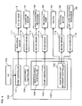
- FIG. 4 is a block diagram schematically showing a controller.
- the controller 100 is made up of a CPU (Central Processing Unit), a ROM (Read Only Memory), a RAM (Random Access Memory), and the like, which work as a print controller 101, a conveyance controller 102, and a maintenance controller 103 as shown in FIG. 4 .
- a CPU Central Processing Unit
- ROM Read Only Memory
- RAM Random Access Memory
- the print controller 101 controls a head drive circuit 111 to eject ink from the corresponding ink-jet head 2.
- the conveyance controller 102 controls a motor driver 112 so as to drive a conveyor motor 97 thereby conveying a paper on the conveyor belt 8.
- the maintenance controller 103 has a head elevation controller 104, a pump controller 105, and a maintenance unit movement controller 106 which is a movement control unit.
- the head elevation controller 104 controls the head elevation mechanism 98 in accordance with a maintenance operation, to move up and down the ink-jet head 2 together with the elevation frame.
- the pump controller 105 controls a pump driver 114 so as to drive an ink supply pump 96 to forcibly feed ink into the ink-jet heads 2.
- the maintenance unit movement controller 106 controls a motor driver 115 to thereby drive the rotation motor 95, so as to make the belt 73 travel in a predetermined direction in accordance with a maintenance operation so that the caps 61, 62 and the wipers 63, 64 move together with the support plates 71, 72.
- the maintenance controller 106 also controls the clutch 84 corresponding to the head group 3a, 3b, 3c, or 3d to be subjected to a maintenance operation. Further, the maintenance unit movement controller 106 controls a motor driver 116 in such a manner that the cap level adjusting mechanism 99 moves down the caps 61, 62 to a lower level, in order that the wipers 63, 64 can wipe the ink ejection faces 4.
- the maintenance unit movement controller 106 is able to switch only one clutch 84 so as to transmit power from the rotation motor 95 to the belt 73. Therefore, only the ink ejection faces 4 in one head group can be wiped by the wipers 63, 64.
- the maintenance unit movement controller 106 may not selectively cause electromagnetic coupling in the clutch 84 for each of the head groups 3a, 3b, 3c, and 3d, but instead may cause electromagnetic coupling in all of the four clutches 84. This can shorten a time required for wiping all the ink ejection faces 4 by the wipers 63, 64.
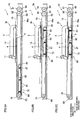
- FIGs. 5A, 5B, and 5C show, over time, a purge operation on ink-jet heads and a wiping operation on ink ejection faces.
- FIGs. 6A, 6B, and 6C show, over time, a capping operation for covering the ink ejection faces with caps.
- the head elevation controller 104 controls the head elevation mechanism 98 so that the ink-jet head 2 targeted for the purge operation and the ink-jet head 2 grouped with the targeted ink-jet head 2 are moved up from the printing position to the head maintenance position, as shown in FIG. 5A . Then, electromagnetic coupling is caused in the clutch 84 which corresponds to the head group including the ink-jet head 2 targeted for the purge operation, so that the caps 61, 62 associated with the ink-jet head 2 targeted for the purge operation and the ink-jet head 2 grouped with the targeted ink-jet head 2 are moved from the cap withdrawal position to the capping position.
- the maintenance unit movement controller 106 rotates the rotation motor 95 so as to rotate the gear 92 in the clockwise direction in FIG. 5A and thereby rotate the belt roller 74 in the counterclockwise direction in FIG. 5A , so that the portions of the belt 73 extending in the main scanning direction travel in the main scanning direction.
- the cap 61 moves leftward in FIG. 1 along the main scanning direction
- the cap 62 moves rightward in FIG. 1 (rightward in FIG. 5A ) along the main scanning direction.
- the wipers 63, 64 mounted on the same support plates 71, 72 also move together with the caps 61, 62, respectively.
- the pump controller 105 supplies ink from a supply pump 96 to the ink-jet heads 2, to thereby perform a purge operation for ejecting ink from the nozzles 4a of the ink-jet heads 2 toward the caps 61, 62.
- the maintenance unit movement controller 106 rotates the rotation motor 95 in the reverse direction so as to rotate the gear 92 in the counterclockwise direction in FIG. 5A and thereby rotate the belt roller 74 in the clockwise direction in FIG. 5A , so that the portions of the belt 73 extending in the main scanning direction travel in the main scanning direction, in order that the caps 61, 62 move from the capping position to the cap withdrawal position.
- the cap 61 moves rightward in FIG. 1 along the main scanning direction, and the cap 62 moves leftward in FIG. 1 (leftward in FIG. 5A ) along the main scanning direction.
- the motor driver 116 controls the cap level adjusting mechanism 99 to move down the caps 61, 62, as shown in FIG. 5B .
- the caps 61, 62 are moved down to such a degree that the distal ends (upper ends) of the wipers 63, 64 come higher than upper ends of the caps 61, 62 are.
- the head elevation controller 104 controls the head elevation mechanism 98 to move down the ink-jet head 2 which has been moved up, to such a degree that the ink ejection faces 4 come slightly lower than the distal ends of the wipers 63, 64 and higher than the upper ends of the caps 61, 62, as shown in FIG. 5C .
- the maintenance unit movement controller 106 rotates the rotation motor 95 so as to rotate the gear 92 in the clockwise direction in FIG. 5C and thereby rotate the belt roller 74 in the counterclockwise direction in FIG.
- the wiper 63, 64 moves from an inner end of the ink ejection face 4 to be wiped (one end of the outside region 4c) toward an outer end thereof with respect to the main scanning direction. At a position where the wiper 63, 64 reaches the outer end of the ink ejection face 4 (the other end of the outside region 4c), the wiper 63, 64 stops its wiping operation.
- the head elevation controller 104 controls the head elevation mechanism 98 to move up the ink-jet heads 2 so as to separate the wipers 63, 64 from the ink ejection faces 4. Then, the wipers 63, 64 are moved to the wiper withdrawal position. In this way, the maintenance operation is completed in which the ink-jet head 2 showing ink ejection failure is restored by the purge and ink adhering to the ink ejection face 4 as a result of the purge is wiped off.
- the head elevation controller 104 controls the head elevation mechanism 98 to move up the ink-jet head 2 targeted for the capping operation and the ink-jet head 2 grouped with the targeted ink-jet head 2 from the printing position to the head maintenance position (see FIG. 6A ). Then, as shown in FIG.
- the head elevation controller 104 controls the head elevation mechanism 98 to move down the ink-jet heads 2 to such a degree that the ink ejection faces 4 come into contact with the upper ends of the caps 61, 62, as shown in FIG. 6C . In this way, an enclosed space is formed between the ink ejection face 4 and the cap 61, 62, which can prevent ink existing within the nozzles 4a from drying up.
- the ink ejection faces 4 of the eight ink-jet heads 2 are arranged in such a manner that the ink ejection faces 4 form two rows each including four ink ejection faces which are arranged side by side along the sub scanning direction and in addition the ink ejection faces 4 included in different rows do not overlap each other with respect to the main scanning direction.
- a free space appears in a region neighboring each ink-jet head 2 with respect to the main scanning direction.
- a plurality of wipers 63, 64 associated with the respective ink-jet heads 2 are positioned in the space.
- the wipers 63, 64 can be selected and moved in units of two wipers 63, 64 associated with each head group, by the control made by the maintenance unit movement controller 106. Accordingly, it is possible that, for example, only the ink ejection faces 4 in the head group which needs a purge operation and wiping can be wiped off by the wipers 63, 64.
- a space formed between the head groups 3a, 3b, 3c, 3d can be made small, because the portions of the belt 73 extending in the main scanning direction are opposed to each other with respect to the vertical direction.
- a length of the belt can be made relatively short, which can reduce a load placed on the rotation motor which is a drive source.
- a plurality of caps 61, 62 associated with each ink-jet head 2 are positioned in the free space neighboring each ink-jet head 2 with respect to the main scanning direction. This can further reduce the size of the ink-jet printer 1.
- the caps 61, 62 can be selected and moved in units of two caps 61, 62 associated with each head group, by the control made by the maintenance unit movement controller 106.
- the cap 61, 62 associated with an ink-jet head 2 is located at such a position that the wiper 63, 64 associated with the ink-jet head 2 is sandwiched between the cap 61, 62 and the ink-jet head 2 with respect to the main scanning direction. This can still further reduce the size of the ink-jet printer 1.
- FIG. 7 is a plan view of an essential part of the ink-jet printer according to the second embodiment of the present invention.
- the ink-jet printer 201 of this embodiment is the same as of the first embodiment, except that a movement mechanism 270 has a difference structure from the structure of the movement mechanism 70 of the first embodiment.
- the same members as of the first embodiment will be denoted by the same reference signs without specific descriptions thereof.
- the movement mechanism 270 of this embodiment has a shaft 290, sixteen belt rollers 291, four belts 273, four support plates 271, four support plates 272, and a power transmission mechanism 280.
- the shaft 290 extends in the sub scanning direction and is supported rotatably about an axis thereof.
- the four belts 273 correspond to the respective head groups 3a, 3b, 3c, and 3d. Each of the four belts 273 is wound on four belt rollers 291 to span the four belt rollers 291.
- the four support plates 271 are, at one-end (upper-end in FIG. 7 ) portions thereof with respect to the sub scanning direction, coupled with the belts 273.
- Each of the four support plates 271 supports the cap 61 and the wiper 63 associated with each ink-jet head 2 included in one (right one in FIG. 7 ) of rows.
- Each of the four support plates 272 supports the cap 62 and the wiper 64 associated with each ink-jet head 2 included in the other (left one in FIG. 7 ) of the rows.
- the power transmission mechanism 280 transmits rotational power to the four belt rollers 291 corresponding to each of the head groups 3a, 3b, 3c, and 3d.
- Each of the support plates 271 supports the cap 61 and the wiper 63 associated with each ink-jet head 2 included in the left row in FIG. 7 .
- the support plate 271 is coupled with a portion of the belt 273 extending in the main scanning direction.
- Each of the support plates 272 supports the cap 62 and the wiper 64 associated with each ink-jet head 2 included in the right row in FIG. 7 .
- the support plate 272 is coupled with a portion of the belt 273 extending in the main scanning direction.
- the eight support plates 271 and 272 are arranged in a zigzag pattern inverse to the zigzag arrangement pattern of the eight ink-jet heads 2.
- the sixteen belt rollers 291 are rotatably supported within the tray 69 in such a manner that, in a plan view, each of the four belts 273 encloses two ink-jet heads 2 forming a head group, and two caps 61, 62 and two wipers 63, 64 associated with the head group. As a result, spaces formed between the head groups can be made small.
- the power transmission mechanism 280 has a gear 292, four gears 296, four gears 285, and four clutches 284.
- the gear 292 s fixed to one end (upper end in FIG. 7 ) of the shaft 290 so as to be rotatable with the shaft 290 about an axis of the shaft 290.
- the four gears 296 are fixed to the shaft 290 at positions along the sub scanning direction which correspond to the respective head groups 3a, 3b, 3c, and 3d.
- the four gears 296 are rotatable with the shaft 290 about the axis of the shaft 290.
- the four gears 285 are engaged with the four gears 296 to thereby rotate with the four gears 296.
- each of the four gears 285 is rotatably fixed to the belt roller 291 located at an upper left portion of each belt 273.
- the four clutches 284 transmit rotational power of the shaft 290 to the four gears 296.
- the clutch 284 has an input shaft 284a fixed to the shaft 290, and an output shaft 284b fixed to the gear 296.
- the clutch 284 has such a structure that the input shaft 284a and the output shaft 284b are electromagnetically coupled with each other so that power is transmitted from the input shaft 284a to the output shaft 284b. Therefore, as the input shaft 284a rotates, the output shaft 284b rotates accordingly.
- the input shaft 284a and the output shaft 284b are decoupled, power is no longer transmitted from the input shaft 284a to the output shaft 284b. Therefore, even when the input shaft 284a rotates, the output shaft 284b does not rotate.
- the belt 273 corresponding to each of the head groups 3a, 3b, 3c, and 3d can be selectively run, by switching a state of the clutch 284 corresponding to each of the head groups 3a, 3b, 3c, and 3d between a state where the input shaft 284a and the output shaft 284b are electromagnetically coupled with each other and a state where they are not electromagnetically coupled with each other.
- the cap 61 and the wiper 63 mounted on the support plate 271 and associated with the head group for which the clutch 284 is electromagnetically coupled are moved together with the support plate 271, leftward in FIG. 7 from the withdrawal position (as shown in FIG. 7 ) which is not opposed to the corresponding ink ejection face 4.
- the cap 62 and the wiper 64 mounted on the support plate 272 and associated with the head group for which the clutch 284 is electromagnetically coupled are moved together with the support plate 272, rightward in FIG. 7 from the withdrawal position (as shown in FIG. 7 ) which is not opposed to the corresponding ink ejection face 4.
- the two caps 61, 62 and the two wipers 63, 64 associated with the head group for which the clutch 284 is electromagnetically coupled can be moved to capping positions which are opposed to the corresponding ink ejection faces 4. That is, the eight caps 61, 62 and the eight wipers 63, 64 associated with all of the four head groups 3a, 3b, 3c, and 3d can be moved to positions opposed to the respective ink ejection faces 4, by electromagnetically coupling all of the four clutches 284.
- the cap 61 and the wiper 63 mounted on the support plate 271 and associated with the head group for which the clutch 284 is electromagnetically coupled are moved rightward in FIG. 7 from the capping position opposed to the corresponding ink ejection face 4.
- the cap 62 and the wiper 64 mounted on the support plate 272 and associated with the head group for which the clutch 284 is electromagnetically coupled are moved leftward in FIG. 7 from the capping position opposed to the corresponding ink ejection face 4.
- the caps 61, 62 and the wipers 63, 64 associated with the head group for which the clutch 284 is electromagnetically coupled can be moved to the withdrawal positions which are not opposed to the corresponding ink ejection faces 4. That is, the eight caps 61, 62 and the eight wipers 63, 64 associated with all of the four head groups 3a, 3b, 3c, and 3d can be moved to the withdrawal positions not opposed to the respective ink ejection faces 4, by electromagnetically coupling all of the four clutches 284.
- the ink ejection faces 4 of the eight ink-jet heads 2 are arranged in such a manner that the ink ejection faces 4 form two rows each including four ink ejection faces 4 which are arranged side by side along the sub scanning direction and in addition the ink ejection faces 4 included in different rows do not overlap each other with respect to the main scanning direction.
- a free space appears in a region neighboring each ink-jet head 2 with respect to the main scanning direction.
- a plurality of wipers 63, 64 associated with the respective ink-jet heads 2 are positioned in the space.
- the wipers 63, 64 can be selected and moved in units of two wipers 63, 64 associated with each head group, by the control made by the maintenance unit movement controller 106. Accordingly, it is possible that, for example, only the ink ejection faces 4 in the head group which needs a purge operation and wiping can be wiped off by the wipers 63, 64.
- FIG. 8 is a plan view of an essential part of the ink-jet printer according to the third embodiment of the present invention.
- neighboring ones of head groups 303a, 303b, 303c, and 303d with respect to the sub scanning direction are oriented in opposite directions, which is different from the arrangement of the head groups 3a, 3b, 3c, and 3d of the first embodiment. Accordingly, arrangement of eight caps 361, 362 and eight wipers 363, 364 is also different from the arrangement of the eight caps 61, 62 and the eight wipers 63, 64 of the first embodiment.
- a maintenance unit 360 of the ink-jet printer 301 has a movement mechanism 370 which is slightly different from the movement mechanism 270 of the second embodiment. Except for the above, the third embodiment is the same as the first embodiment.
- ink-jet heads 302, caps 361, 362, and wipers 363, 364 are the same as in the first embodiment, but only arrangements thereof are different from in the first embodiment.
- the same members as of the first embodiment will be denoted by the same reference signs without specific descriptions thereof.
- the eight ink-jet heads 302 of this embodiment are arranged in a zigzag pattern in such a manner that the ink ejection faces 4 form two rows each including four ink ejection faces 4 which are arranged side by side along the sub scanning direction and in addition the ink ejection faces 4 included in different rows do not overlap each other with respect to the main scanning direction.
- the eight ink-jet heads 302 are divided into four head groups 303a, 303b, 303c, and 303d each of which includes two ink-jet heads 302. Ink ejection faces 4 of the two ink-jet heads 302 neighbor each other with respect to the sub scanning direction and belong to different rows.
- the four head groups 303a, 303b, 303c, and 303d are arranged side by side along the sub scanning direction.
- One (left one in FIG. 8 ) of the two ink-jet heads 302 in the head group 303a and one of the two ink-jet heads 302 in the head group 303b are located in positions which are the same with respect to the main scanning direction and adjacent to each other with respect to the sub scanning direction.
- the other (right one in FIG. 8 ) of the two ink-jet heads 302 in the head group 303b and the other of the two ink-jet heads 302 in the head group 303c are located in positions which are the same with respect to the main scanning direction and adjacent to each other with respect to the sub scanning direction.
- One of the two ink-jet heads 302 in the head group 303c and one of the two ink-jet heads 302 in the head group 303d are located in positions which are the same with respect to the main scanning direction and adjacent to each other with respect to the sub scanning direction.
- two caps 361, 362 and two wipers 363, 364 associated with two adjacent ink-jet heads 302 which belong to neighboring two of the head groups 303a, 303b, 303c, and 303d can be disposed at positions which are the same with respect to the main scanning direction and adjacent to each other with respect to the sub scanning direction.
- the two ink-jet heads 2 belonging to each of the head groups 303a, 303b, 303c, and 303d have their ink ejection faces 4 overlap each other with respect to the sub scanning direction, which is the same structure as that of the head groups 3a, 3b, 3c, and 3d of the first embodiment.
- the maintenance unit 360 has eight caps 361, 362 and eight wipers 363, 364 associated with the eight ink-jet heads 302, respectively.
- the maintenance unit 360 also has a movement mechanism 370 which moves the caps 361, 362 and the wipers 363, 364 in the main scanning direction.
- the movement mechanism 370 has a shaft 390, sixteen belt rollers 391, four belts 373, four support plates 371, four support plates 372, and a power transmission mechanism 380.
- the shaft 390 extends in the sub scanning direction and is supported rotatably about an axis thereof.
- the four belts 373 correspond to the respective head groups 303a, 303b, 303c, and 303d.
- Each of the four belts 373 is wound on four belt rollers 391 to span the four belt rollers 391.
- the four support plates 371 are, at one-end (upper-end in FIG. 8 ) portions thereof with respect to the sub scanning direction, coupled with the belts 373.
- Each of the four support plates 371 supports the cap 361 and the wiper 363 associated with each ink-jet head 302 included in one (right one in FIG. 8 ) of rows.
- Each of the four support plates 372 supports the cap 362 and the wiper 364 associated with each ink-jet head 302 included in the other (left one in FIG. 8 ) of the rows.
- the power transmission mechanism 380 transmits rotational power to one belt roller 391 corresponding to each of the head groups 303a, 303b, 303c, and 303d.
- Each of the support plates 371 supports the cap 361 and the wiper 363 associated with each ink-jet head 302 included in the left row in FIG. 8 .
- the support plate 371 is coupled with a portion of the belt 373 extending in the main scanning direction.
- Each of the support plates 372 supports the cap 362 and the wiper 364 associated with each ink-jet head 302 included in the right row in FIG. 8 .
- the support plate 372 is coupled with a portion of the belt 373 extending in the main scanning direction.
- the sixteen belt rollers 391 are rotatably supported within the tray 69 in such a manner that, in a plan view, each of the four belts 373 encloses two ink-jet heads 302 forming a head group, and two caps 361, 362 and two wipers 363, 364 associated with the head group. As a result, spaces formed between the head groups can be made small.
- the power transmission mechanism 380 has a gear 392, two gears 396a, two gears 396b, four gears 385a, 385b, and clutches 384.
- the gear 392 is fixed to one end (upper end in FIG. 8 ) of the shaft 390 so as to be rotatable with the shaft 390 about an axis of the shaft 390.
- the two gears 396a are supported at positions along the sub scanning direction which correspond to the respective head groups 303a and 303d.
- the two gears 396a are rotatable with the shaft 390 about the axis of the shaft 390.
- the two gears 396b are supported at positions along the sub scanning direction which correspond to the respective head groups 303b and 303c.
- the two gears 396b are rotatable with the shaft 390 about the axis of the shaft 390.
- the four gears 385a and 385b are engaged with the four gears 396a and 396b to thereby rotate with the gears 396a and 396b.
- each of four gears 385a and 385b is rotatably fixed to the belt roller 391 located at an upper left portion of each belt 373.
- the four clutches 384 transmit rotational power of the shaft 390 to the four gears 396a and 396b.
- the gear 396a rotates in a predetermined direction to thereby rotate the gear 385a in the clockwise direction in FIG. 8 .
- the gear 396b whose threaded direction is reversed to that of the gear 396a, rotates in a predetermined direction to thereby rotate the gear 385b in the counterclockwise direction in FIG. 8 .
- the clutch 384 has an input shaft 384a fixed to the shaft 390, and an output shaft 384b fixed to the gear 396a, 396b.
- the clutch 384 has such a structure that the input shaft 384a and the output shaft 384b are electromagnetically coupled with each other so that power is transmitted from the input shaft 384a to the output shaft 384b. Therefore, as the input shaft 384a rotates, the output shaft 384b rotates accordingly.
- the input shaft 384a and the output shaft 384b are decoupled, power is no longer transmitted from the input shaft 384a to the output shaft 384b. Therefore, even when the input shaft 384a rotates, the output shaft 384b does not rotate.
- each belt 373 can be selectively run, by switching a state of the clutch 384 corresponding to each of the head groups 303a, 303b, 303c, and 303d between a state where the input shaft 384a and the output shaft 384b are electromagnetically coupled with each other and a state where they are not electromagnetically coupled with each other.
- the cap 361 and the wiper 363 mounted on the support plate 371 and associated with the head group for which the clutch 384 is electromagnetically coupled are moved together with the support plate 371, leftward in FIG. 8 from the withdrawal position (as shown in FIG. 8 ) which is not opposed to the corresponding ink ejection face 4.
- the cap 362 and the wiper 364 mounted on the support plate 372 and associated with the head group for which the clutch 384 is electromagnetically coupled are moved together with the support plate 372, rightward in FIG. 8 from the withdrawal position which is not opposed to the corresponding ink ejection face 4.
- the two caps 361, 362 and the two wipers 363, 364 associated with the head group for which the clutch 384 is electromagnetically coupled can be moved to capping positions which are opposed to the corresponding ink ejection faces 4. That is, the eight caps 361, 362 and the eight wipers 363, 364 associated with all of the four head groups 303a, 303b, 303c, and 303d can be moved to positions opposed to the respective ink ejection faces 4, by electromagnetically coupling all of the four clutches 384.
- the cap 361 and the wiper 363 mounted on the support plate 371 and associated with the head group for which the clutch 384 is electromagnetically coupled are moved rightward in FIG. 8 from the capping position opposed to the corresponding ink ejection face 4.
- the cap 362 and the wiper 364 mounted on the support plate 372 and associated with the head group for which the clutch 384 is electromagnetically coupled are moved leftward in FIG. 7 from the capping position opposed to the corresponding ink ejection face 4.
- the caps 361, 362 and the wipers 363, 364 associated with the head group for which the clutch 384 is electromagnetically coupled can be moved to the withdrawal positions which are not opposed to the corresponding ink ejection faces 4. That is, the eight caps 361, 362 and the eight wipers 363, 364 associated with all of the four head groups 303a, 303b, 303c, and 303d can be moved to the withdrawal positions not opposed to the respective ink ejection faces 4, by electromagnetically coupling all of the four clutches 384.
- the ink ejection faces 4 of the eight ink-jet heads 302 are arranged in such a manner that the ink ejection faces 4 form two rows each including four ink ejection faces 4 which are arranged side by side along the sub scanning direction and in addition the ink ejection faces 4 included in different rows do not overlap each other with respect to the main scanning direction.
- a free space appears in a region neighboring each ink-jet head 302 with respect to the main scanning direction.
- a plurality of wipers 363, 364 corresponding to the respective ink-jet heads 302 are positioned in the space.
- the wipers 363, 364 can be selected and moved in units of two wipers 363, 364 associated with each head group, by the control made by the maintenance unit movement controller 106. Accordingly, it is possible that, for example, only the ink ejection faces 4 in the head group which needs a purge operation and wiping can be wiped off by the wipers 363, 364.
- two ink-jet heads which eject ink of the same color are arranged so as to allow printing to be made continuously without a break in the main scanning direction when these two ink-jet heads eject ink to form an image.
- the two ink-jet heads do not overlap each other with respect to the sub scanning direction so as to allow noncontinuous printing having a break in the main scanning direction when an image is formed.
- the ink-jet printers according to the embodiments may not include the caps.
- the belt by rotational drive of a single rotation motor, the belt is run to selectively move the caps and wipers.
- different rotation motors may be provided for the respective belts.
- the belt can be selectively run to selectively move the caps and wipers on a head group basis. That is, a rotation motor may be provided for every head group, as a switching means. At this time, it is not necessary to provide the clutch.
- the above-described embodiments are examples of application of the present invention to an ink-jet printer including a plurality of ink-jet heads which eject ink from nozzles.
- an ink-jet head is not the only thing to which the present invention is applicable.
- the present invention may be applied to various image recording apparatus including a plurality of liquid ejection heads for ejecting a conductive paste to form a fine wiring pattern on a substrate, for ejecting an organic luminescent material to a substrate to form a high-resolution display, and for ejecting optical plastics to a substrate to form a very small electronic device such as an optical waveguide.
Landscapes
- Ink Jet (AREA)
Abstract
Description
- The present invention relates to an image recording apparatus having a liquid ejection head which ejects liquid.
- Japanese Unexamined Patent Publication No.
2005-132025 - In the ink-jet printer disclosed in Japanese Unexamined Patent Publication No.
2005-132025 - An object of the present invention is to provide an image recording apparatus which can be downsized even if they have a plurality of liquid ejection heads.
- According to an aspect of the present invention, there is provided an image recording apparatus comprising a plurality of liquid ejection heads, a recording medium conveyance mechanism, a plurality of wipers, and a movement mechanism. The plurality of liquid ejection heads respectively have ejection faces which are arranged in such a manner that the ejection faces form two rows extending in one direction and in addition two of the ejection faces included in different rows do not overlap each other along a direction perpendicular to the one direction with respect to an in-plane direction of the ejection faces. The plurality of liquid ejection heads are divided into a plurality of head groups each including two of the liquid ejection heads corresponding to the different rows. The recording medium conveyance mechanism conveys a recording medium in the one direction while making the recording medium opposed to the ejection faces. The plurality of wipers wipe the ejection faces of the liquid ejection heads. The movement mechanism moves two of the wipers for wiping two ejection faces of the two liquid ejection heads belonging to each head group, in opposite directions with respect to the perpendicular direction while keeping the two wipers in contact with the ejection faces. When in a wiper withdrawal position not opposed to the ejection face, the wiper associated with one of the liquid ejection heads belonging to each head group is positioned so as to overlap the one liquid ejection head along the perpendicular direction and in addition overlap the other of the liquid ejection heads along the one direction, while, when in the wiper withdrawal position, the wiper associated with the other liquid ejection head is positioned so as to overlap the other liquid ejection head along the perpendicular direction and in addition overlap the one liquid ejection head along the one direction.
- In this aspect, ejection faces of the plurality of liquid ejection heads are arranged in two rows extending along one direction, in such a manner that two ejection faces belonging to different rows do not overlap each other along a direction perpendicular to the one direction. As a result, a free space appears in a region neighboring each liquid ejection head with respect to the perpendicular direction. A plurality of wipers associated with the respective liquid ejection heads are withdrawn into the space. Withdrawing the wipers into the free space in this way makes it unnecessary to provide another space which is special for the wipers to be positioned therein. Therefore, downsizing of the image recording apparatus can be realized.
- In the image recording apparatus, each of the plurality of head groups is made up of two of the liquid ejection heads which eject liquid of the same color, and the movement mechanism selectively moves the plurality of wipers in units of the two wipers associated with the head group. The image recording apparatus further comprises a movement control means which controls the movement mechanism in such a manner that the two wipers associated with, among the plurality of head groups, the selected head group wipe two ejection faces in the head group. With this structure, the wipers can be selected and moved in units of two wipers associated with each head group, by the control made by the movement control means. Accordingly, it is possible that only the ejection faces in the head group which needs wiping can be wiped off by the wipers.
- In the image recording apparatus, the movement mechanism includes a plurality of belts each of which is coupled with the two wipers associated with the head group and travels along the perpendicular direction to thereby move the two wipers in the opposite directions, and a plurality of switching means each of which can be switched between a state of transmitting power from a drive source to the belt and a state of transmitting power from the drive source to the belt. The movement control means switches at least one of the switching means into the state of transmitting power from the drive source to the belt. With this structure, the movement control means is able to switch only one switching means so as to transmit power from the drive source to the belt. Therefore, only the ejection faces in one head group can be wiped by the wipers.
- In the image recording apparatus, the movement control means switches all the switching means into the state of transmitting power from the drive source to the belt. With this structure, the movement control means can switch all the switching means so as to transmit power from the drive source to the belt. Therefore, the ejection faces in all the head groups can be wiped by the wipers. This can shorten a time required for wiping all the ejection faces by the wipers.
- In the image recording apparatus, each of the plurality of belts is disposed so as to, in a plan view, enclose the two liquid ejection heads belonging to the head group and the two wipers associated with the head group. As a result, a space formed between the head groups can be made small.
- In the image recording apparatus, each of the plurality of belts is disposed between the two liquid ejection heads belonging to the head group, in such a manner that portions of the belt extending in the perpendicular direction are opposed to each other with respect to a vertical direction. With this structure, even when the belt is disposed between the head groups, a space formed between the head groups can be made small, because the portions of the belt extending in the perpendicular direction are opposed to each other with respect to the vertical direction. In addition, a length of the belt can be made relatively short, which can reduce a load placed on the drive source.
- The image recording apparatus further comprises a plurality of caps which cover the ejection faces by being in contact with the ejection faces. Each belt is coupled with two of the caps which are associated with the two liquid ejection heads belonging to the head group, and travels along the perpendicular direction so that the two caps move in the opposite directions along the perpendicular direction between a capping position opposed to the ejection face and a cap withdrawal position not opposed to the ejection face. With this structure, the plurality of caps can also be selected and moved in units of two caps associated with the head group.
- In the image recording apparatus, when in the cap withdrawal position, the cap associated with the one liquid ejection head is positioned so as to overlap the one liquid ejection head along the perpendicular direction and in addition overlap the other liquid ejection head along the one direction, while, when in the cap withdrawal position, the cap associated with the other liquid ejection head is positioned so as to overlap the other liquid ejection head along the perpendicular direction and in addition overlap the one liquid ejection head along the one direction. With this structure, the plurality of caps associated with the respective liquid ejection heads are positioned in the free space neighboring each liquid ejection head with respect to the perpendicular direction. This can further reduce the size of the liquid ejection apparatus.
- In the image recording apparatus, when the wiper is disposed in the wiper withdrawal position, the cap associated with the liquid ejection head is located in such a position that the wiper associated with the liquid ejection head is sandwiched between the cap and the liquid ejection head with respect to the perpendicular direction. This can still further reduce the size of the liquid ejection apparatus.
- Other and further objects, features and advantages of the invention will appear more fully from the following description taken in connection with the accompanying drawings in which:
-
FIG. 1 is a plan view of an essential part of an ink-jet printer according to a first embodiment of the present invention; -
FIG. 2 is a sectional view as taken along line II-II illustrated inFIG. 1 ; -
FIG. 3 shows four head groups illustrated inFIG. 1 , as seen from a bottom side thereof; -
FIG. 4 is a block diagram schematically showing a controller; -
FIGs. 5A, 5B, and 5C show, over time, a purge operation on ink-jet heads and a wiping operation on ink ejection faces; -
FIGs. 6A, 6B, and 6C show, over time, a capping operation for covering the ink ejection faces with caps; -
FIG. 7 is a plan view of an essential part of an ink-jet printer according to a second embodiment of the present invention; and -
FIG. 8 is a plan view of an essential part of an ink-jet printer according to a third embodiment of the present invention. -
FIG. 1 is a plan view of an essential part of an ink-jet printer according to a first embodiment of the present invention.FIG. 2 is a sectional view as taken along line II-II illustrated inFIG. 1 .FIG. 3 shows four head groups illustrated inFIG. 1 , as seen from a bottom side thereof. - As shown in
FIG. 1 , an ink-jet printer 1, which is an image recording apparatus according to a first embodiment of the present invention, is a color ink-jet printer of line type including fourhead groups jet heads 2 or liquid ejection heads. The ink-jet printer 1 has a paper feed unit (not shown) and a paper discharge unit (not shown) at upper and lower parts ofFIG. 1 , respectively. - In the ink-jet printer 1, a
paper conveyance mechanism 10 which is a recording medium conveyance mechanism is provided between the paper feed unit and the paper discharge unit, at a position opposed to the fourhead groups paper conveyance mechanism 10 conveys a paper as a recording medium to a position opposed to ink ejection faces 4 which are ejection faces of the eight ink-jet heads 2. As shown inFIG. 1 , thepaper conveyance mechanism 10 has a pair ofbelt rollers head groups FIG. 1 ), and anendless conveyor belt 8 which is wound on the pair ofbelt rollers FIG. 4 ) applies driving force to thebelt roller 7 which is thereby rotated in a predetermined direction. As thebelt roller 7 rotates in the predetermined direction, theconveyor belt 8 travels so as to convey the paper in a paper conveyance direction A (i.e., in a direction from up to down inFIG. 1 ). - The
conveyor belt 8 has a two-layer structure made up of a base material and urethane rubber. An outer surface of theconveyor belt 8, that is, aconveyor face 9 has adhesiveness. A paper fed out from the paper feed unit is maintained due to the adhesiveness of theconveyor face 9, and in this condition conveyed in the conveyance direction A. - Each ink-
jet head 2 has a rectangular parallelepiped shape elongated in a main scanning direction (which is a direction perpendicular to the paper conveyance direction A: a perpendicular direction), as shown inFIGs. 1 and2 . Each ink-jet head 2 has a headmain body 5 at its lower end. - A reservoir unit which temporarily stores ink therein is fixed to an upper face of the head
main body 5. The reservoir unit is partially covered with acover 14. Referring toFIG. 1 , a tube joint 11 is connected to a left end of the reservoir unit. Ink supplied through the tube joint 11 is stored in an ink reservoir which is formed within the reservoir unit. The reservoir unit is longer than the headmain body 5 with respect to the main scanning direction.Portions 12 of the reservoir unit extend out on both sides of the reservoir unit with respect to the main scanning direction. Theportions 12 serve as a fixing portion to be fixed to an elevation frame (not shown) which is provided for every reservoir unit. Each ink-jet head 2 is fixed to the elevation frame via the fixing portion. The elevation frame can be moved up and down by a head elevation mechanism 98 (seeFIG. 4 ). - Normally, the eight ink-
jet heads 2 are disposed in a printing position (i.e., a position of the ink-jet head 2 shown inFIG. 2 ). When the ink-jet heads 2 are in the printing position, eachink ejection face 4 and theconveyor face 9 of theconveyor belt 8 extend in parallel with each other and at a predetermined interval therebetween. With this structure, while a paper conveyed by theconveyor belt 8 is passing immediately below the eight headmain bodies 5 sequentially, a desired image is formed on the paper. For a maintenance operation on the ink-jet head 2, on the other hand, thehead elevation mechanism 98 moves up the elevation frame to which an ink-jet head 2 to be subjected to the maintenance operation is fixed. This brings the ink-jet head 2 fixed to this elevation frame into a head maintenance position (seeFIG. 5A ) which is above and away from the printing position. During the maintenance operation, only the ink-jet head 2 to be subjected to the maintenance operation may be disposed in the maintenance position or alternatively all of the eight ink-jet heads 2 may be disposed in the maintenance position. - As shown in
FIG. 3 , small-diameter nozzles 4a which eject ink, anink ejection region 4b which is formed by a collection of thenozzles 4a, and anoutside region 4c which surrounds theink ejection region 4b are provided on a bottom face of the headmain body 5, that is, on theink ejection face 4 of the ink-jet head 2. - As shown in
FIGs. 1 and3 , the eight ink-jet heads 2 are arranged in a zigzag pattern in such a manner that the ink ejection faces 4 form two rows each including four ink ejection faces 4 which are arranged side by side along the sub scanning direction and in addition the ink ejection faces 4 included in different rows do not overlap each other with respect to the main scanning direction. The eight ink-jet heads 2 are divided into fourhead groups jet heads 2 neighbor each other with respect to the sub scanning direction and belong to different rows. The fourhead groups jet heads 2 in a zigzag pattern with respect to the sub scanning direction. - Two ink-
jet heads 2 included in each of thehead groups ink ejection regions 4b) for making printing on a paper continue in the main scanning direction. More specifically, two ink-jet heads 2 included in the same head group are arranged in such a manner that an interval in the main scanning direction between neighboringnozzles 4a in anink ejection region 4b of one ink-jet head 2 is the same as an interval in the main scanning direction between an innermost (i.e., leftmost inFIG. 3 ) one of thenozzles 4a formed in theink ejection face 4 of the right-side ink-jet head 2 inFIG. 3 which is included in thehead group 3a and an innermost (i.e., rightmost inFIG. 3 ) one of thenozzles 4a formed in theink ejection face 4 of the left-side ink-jet head 2 inFIG. 3 which is included in thehead group 3a. Each of theother head groups jet heads 2 arranged in the same manner as in thehead group 3a. The eight ink-jet heads 2 eject ink of four different colors (magenta, yellow, cyan, and black), each color corresponds to each of thehead groups jet heads 2 belonging to the same head group, neighboring each other in the sub scanning direction, and included in different rows eject ink of the same color. - Next, a
maintenance unit 60 which performs maintenance on the ink-jet heads 2 will be described. As shown inFIGs. 1 and2 , themaintenance unit 60 has fourcaps 61 and fourwipers 63, fourcaps 62 and fourwipers 64, amovement mechanism 70, and atray 69. The fourcaps 61 and fourwipers 63 are associated with four ink-jet heads 2 which belong to therespective head groups FIG. 1 ) of the rows. The fourcaps 62 and fourwipers 64 are associated with four ink-jet heads 2 which belong to therespective head groups FIG. 1 ) of the rows. Themovement mechanism 70 moves, on a head group basis, the eightcaps wipers tray 69 contains therein the eightcaps wipers movement mechanism 70. Thetray 69 has a pass through 68a which extends through thetray 69 in a vertical direction. The pass through 68a is at a position opposed to each ink-jet head 2. The pass through 68a has a rectangular shape in a plan view, and has such a size that each of the eight ink ejection faces 4 of the respective ink-jet heads 2 can entirely be opposed to theconveyor face 9. - The
caps base material 65 and anannular protrusion 66. A shape of thebase material 65 is similar to but slightly larger than theink ejection region 4b. Theannular protrusion 66 stands at a periphery of thebase material 65. This structure allows thecaps ink ejection regions 4b with distal ends of theannular protrusions 66 being in contact with theoutside regions 4c of the ink ejection faces 4.
Thereby, drying of ink existing within thenozzles 4a can be suppressed. - Two
recesses 65a which open upward in the vertical direction are formed in thebase material 65. The tworecesses 65a are disposed side by side along the main scanning direction. A throughhole 65b is formed at a bottom of therecess 65a. Since the throughholes 65b are formed, ink ejected into thecaps recess 65a can be discarded through the throughholes 65b into a not-shown waste ink reservoir. - As shown in
FIG. 2 , each of thecaps springs 67. Since each of thecaps springs 67, impact caused when theannular protrusion 66 comes into contact with theink ejection face 4 can be softened, so that theink ejection face 4 is not easily damaged by theannular protrusion 66. - The
maintenance unit 60 also has a cap level adjusting mechanism 99 (seeFIG. 4 ) which moves down thecaps wipers level adjusting mechanism 99 moves down thecaps wipers caps caps - As shown in
FIG. 1 , each of thewipers jet head 2 and acap jet head 2. A length of extension of thewiper ink ejection face 4 of the corresponding ink-jet head 2 with respect to the sub scanning direction. Thewipers wipers support plates caps springs 67. In a case where thecaps level adjusting mechanism 99, the distal ends of thewipers caps - When disposed in a withdrawal position not opposed to the ink ejection face 4 (as shown in
FIG. 1 ), thewiper 63 for thehead group 3a locates in a position overlapping the corresponding left-side ink-jet head 2 inFIG. 1 in the main scanning direction and overlapping the right-side ink-jet head 2 inFIG. 1 in the sub scanning direction. When disposed in a withdrawal position not opposed to the ink ejection face 4 (as shown inFIG. 1 ), thewiper 64 for thehead group 3a locates in a position overlapping the corresponding right-side ink-jet head 2 inFIG. 1 in the main scanning direction and overlapping the left-side ink-jet head 2 inFIG. 1 in the sub scanning direction. Thewipers head groups wipers head group 3a are. The withdrawal position is equivalent to a wiper withdrawal position and a cap withdrawal position of the present invention. - As shown in
FIGs. 1 and2 , themovement mechanism 70 has twoshafts shafts 81, fourbelt rollers 74, fourbelt rollers 75, fourbelts 73, eightsupport plates power transmission mechanism 80. The twoshafts shafts 81 extend in the sub scanning direction, and are supported rotatably about an axis thereof. The fourbelt rollers 74 are provided for the fourshafts 81, respectively. The fourbelt rollers 75 are provided on theshaft 93. Each of the fourbelts 73 spans thebelt rollers support plates belts 73, respectively. Thepower transmission mechanism 80 transmits rotational power to eachbelt roller 74. - The four
support plates 71 support thecaps 61 andwipers 63 associated with, among the ink-jet heads of thehead groups jet heads 2 included in one (left one inFIG. 1 ) of the rows extending in the sub scanning direction. The foursupport plates 71 are coupled with portions of thebelts 73 extending in the main scanning direction. Thecap 61 and thewiper 63 are positioned in such a manner that, in a plan view, they overlap the corresponding ink-jet head 2 in the main scanning direction and also overlap the other ink-jet head 2 belonging to the same head group as the corresponding ink-jet head 2 in the sub scanning direction. - The four
support plates 72 support thecaps 62 andwipers 64 associated with, among the ink-jet heads of thehead groups jet heads 2 included in the other (right one inFIG. 1 ) of the rows extending in the sub scanning direction. The foursupport plates 72 are coupled with portions of thebelts 73 extending in the main scanning direction. Thecap 62 and thewiper 64 are positioned in such a manner that, in a plan view, they overlap the corresponding ink-jet head 2 in the main scanning direction and also overlap the other ink-jet head 2 belonging to the same head group as the corresponding ink-jet head 2 in the sub scanning direction. - In other words, with respect to the sub scanning direction, the eight
support plates - The four
belt rollers 75 are mounted on theshaft 93, at positions overlapping therespective head groups belt rollers 75 are supported rotatably in clockwise and counterclockwise directions inFIG. 2 . - The four
belt rollers 74 are mounted on the fourshafts 81, at positions overlapping therespective head groups belt rollers 74 are fixed rotatably in clockwise and counterclockwise directions inFIG. 2 . - Each of the four
belts 73 is wound on a pair ofbelt rollers jet heads 2 belonging to thehead groups belt 73 extending in the main scanning direction are opposed to each other with respect to the vertical direction. Thebelt 73 of this embodiment is a rubber-made flat belt having a very narrow width. However, a rubber belt having a circular section, or a metal-made wire may be adopted for thebelt 73. In short, any member may be adopted as long as it functions as a belt. - The
power transmission mechanism 80 has agear 92, fourgears 91, fourgears 85, andclutches 84. Thegear 92 is fixed to one end (upper end inFIG. 1 ) of theshaft 90 so as to be rotatable with theshaft 90 about an axis of theshaft 90. The four gears 91 are fixed to theshaft 90 at positions along the sub scanning direction which correspond to therespective heads shaft 90 about the axis of theshaft 90. The four gears 85 are engaged with the fourgears 91 to thereby rotate with the four gears 91. Theclutches 84 are four switching means each disposed between each of the fourgears 85 and each of the fourshafts 81. - The clutch 84 has an
input shaft 84a fixed to thegears 85, and anoutput shaft 84b fixed to theshafts 81. The clutch 84 has such a structure that theinput shaft 84a and theoutput shaft 84b are electromagnetically coupled with each other so that power is transmitted from theinput shaft 84a to theoutput shaft 84b. Therefore, as theinput shaft 84a rotates, theoutput shaft 84b rotates accordingly. When theinput shaft 84a and theoutput shaft 84b are decoupled, power is no longer transmitted from theinput shaft 84a to theoutput shaft 84b. Therefore, even when theinput shaft 84a rotates, theoutput shaft 84b does not rotate. - As a rotation motor 95 (see
FIG. 4 ) is driven to rotate thegear 92 in a predetermined direction thereby also rotate theshaft 90 in the same direction, rotational power traveling in a reverse direction is transmitted via the fourgears input shafts 84a of theclutches 84. At this time, when theinput shaft 84a and theoutput shaft 84b are electromagnetically coupled with each other, rotation of theinput shaft 84a in the reverse direction is transmitted to theoutput shaft 84b. Thereby, theshaft 81 and thebelt roller 74, together with theoutput shaft 84b, rotate in the reverse direction. Consequently, thebelt 73 rotates in the direction reverse to the rotation direction of thegear 92. That is, thebelt 73 corresponding to each of thehead groups input shaft 84a and theoutput shaft 84b corresponding to each of thehead groups - The
support plate 71 is coupled with vertically-upper one of the portions of thebelt 73 extending in the main scanning direction. Thesupport plate 72 is coupled with vertically-lower one of the portions of thebelt 73 extending in the main scanning direction. As shown inFIG. 1 , eight sets of twoguide rails 68c extending in the main scanning direction are formed on thetray 69. Each of the eight sets corresponds to each pass through 68a. The pass through 68a is sandwiched between the corresponding twoguide rails 68c with respect to the sub scanning direction. Among the eight sets ofguide rails 68c, four sets which form left one of rows inFIG. 1 arranged side by side along the sub scanning direction are partially opposed to both ends of thesupport plates 71 with respect to the sub scanning direction. The four sets ofguide rails 68c are fitted with recesses which extend in the main scanning direction and are formed at the both ends of thesupport plates 71 with respect to the sub scanning direction. Thereby, the four sets ofguide rails 68c are slidable along the recesses. The other four sets ofguide rails 68c which form right one of the rows inFIG. 1 arranged side by side along the sub scanning direction are partially opposed to both ends of thesupport plates 72 with respect to the sub scanning direction. The four sets ofguide rails 68c are fitted with recesses which extend in the main scanning direction and are formed at the both ends of thesupport plates 72 with respect to the sub scanning direction. Thereby, the four sets ofguide rails 68c are slidable along the recesses. - In the
maintenance unit 60 having the above-described structure, when therotation motor 95 rotates thegear 92 in the clockwise direction inFIG. 2 , thecap 61 and thewiper 63 mounted on thesupport plate 71 and associated with the head group for which the clutch 84 is electromagnetically coupled are moved together with thesupport plate 71, leftward inFIG. 1 from the withdrawal position (as shown inFIG. 1 ) which is not opposed to the correspondingink ejection face 4. In addition, thecap 62 and thewiper 64 mounted on thesupport plate 72 and associated with the head group for which the clutch 84 is electromagnetically coupled are moved together with thesupport plate 72, rightward inFIG. 1 from the withdrawal position which is not opposed to the correspondingink ejection face 4. In this way, the twocaps wipers caps wipers head groups clutches 84. - On the other hand, when the
rotation motor 95 rotates thegear 92 in the counterclockwise direction inFIG. 2 , thecap 61 and thewiper 63 mounted on thesupport plate 71 and associated with the head group for which the clutch 84 is electromagnetically coupled are moved rightward inFIG. 1 from the position opposed to the correspondingink ejection face 4. In addition, thecap 62 and thewiper 64 mounted on thesupport plate 72 and associated with the head group for which the clutch 84 is electromagnetically coupled are moved leftward inFIG. 1 from the position opposed to the correspondingink ejection face 4. In this way, thecaps wipers caps wipers head groups clutches 84. - Next, a
controller 100 which controls an operation of the ink-jet printer 1 will be described with reference toFIG. 4. FIG. 4 is a block diagram schematically showing a controller. Thecontroller 100 is made up of a CPU (Central Processing Unit), a ROM (Read Only Memory), a RAM (Random Access Memory), and the like, which work as aprint controller 101, aconveyance controller 102, and amaintenance controller 103 as shown inFIG. 4 . - When the
controller 100 receives print data from an external device such as a PC (personal computer) 120, theprint controller 101 controls ahead drive circuit 111 to eject ink from the corresponding ink-jet head 2. - When the
controller 100 receives print data from an external device such as thePC 120, theconveyance controller 102 controls amotor driver 112 so as to drive aconveyor motor 97 thereby conveying a paper on theconveyor belt 8. - The
maintenance controller 103 has ahead elevation controller 104, apump controller 105, and a maintenanceunit movement controller 106 which is a movement control unit. - The
head elevation controller 104 controls thehead elevation mechanism 98 in accordance with a maintenance operation, to move up and down the ink-jet head 2 together with the elevation frame. - When a purge is needed, such as when ink is initially introduced into the ink-
jet heads 2 or when printing is started after a rest condition where a printing operation is kept unperformed for a long time, thepump controller 105 controls apump driver 114 so as to drive anink supply pump 96 to forcibly feed ink into the ink-jet heads 2. - The maintenance
unit movement controller 106 controls amotor driver 115 to thereby drive therotation motor 95, so as to make thebelt 73 travel in a predetermined direction in accordance with a maintenance operation so that thecaps wipers support plates maintenance controller 106 also controls the clutch 84 corresponding to thehead group unit movement controller 106 controls amotor driver 116 in such a manner that the caplevel adjusting mechanism 99 moves down thecaps wipers unit movement controller 106 is able to switch only one clutch 84 so as to transmit power from therotation motor 95 to thebelt 73. Therefore, only the ink ejection faces 4 in one head group can be wiped by thewipers unit movement controller 106 may not selectively cause electromagnetic coupling in the clutch 84 for each of thehead groups clutches 84. This can shorten a time required for wiping all the ink ejection faces 4 by thewipers - Next, a maintenance operation performed by the
maintenance unit 60 will be described with reference toFIGs. 5A to 5C andFIGs. 6A to 6C .FIGs. 5A, 5B, and 5C show, over time, a purge operation on ink-jet heads and a wiping operation on ink ejection faces.FIGs. 6A, 6B, and 6C show, over time, a capping operation for covering the ink ejection faces with caps. - For performing a purge operation in order to restore the ink-
jet head 2 which is showing ejection failure or the like, thehead elevation controller 104 controls thehead elevation mechanism 98 so that the ink-jet head 2 targeted for the purge operation and the ink-jet head 2 grouped with the targeted ink-jet head 2 are moved up from the printing position to the head maintenance position, as shown inFIG. 5A . Then, electromagnetic coupling is caused in the clutch 84 which corresponds to the head group including the ink-jet head 2 targeted for the purge operation, so that thecaps jet head 2 targeted for the purge operation and the ink-jet head 2 grouped with the targeted ink-jet head 2 are moved from the cap withdrawal position to the capping position. Then, the maintenanceunit movement controller 106 rotates therotation motor 95 so as to rotate thegear 92 in the clockwise direction inFIG. 5A and thereby rotate thebelt roller 74 in the counterclockwise direction inFIG. 5A , so that the portions of thebelt 73 extending in the main scanning direction travel in the main scanning direction. At this time, thecap 61 moves leftward inFIG. 1 along the main scanning direction, and thecap 62 moves rightward inFIG. 1 (rightward inFIG. 5A ) along the main scanning direction. In other words, thecap 61 and thecap 62 move in opposite directions with respect to the main scanning direction. At this time, thewipers same support plates caps - Then, the
pump controller 105 supplies ink from asupply pump 96 to the ink-jet heads 2, to thereby perform a purge operation for ejecting ink from thenozzles 4a of the ink-jet heads 2 toward thecaps caps unit movement controller 106 rotates therotation motor 95 in the reverse direction so as to rotate thegear 92 in the counterclockwise direction inFIG. 5A and thereby rotate thebelt roller 74 in the clockwise direction inFIG. 5A , so that the portions of thebelt 73 extending in the main scanning direction travel in the main scanning direction, in order that thecaps cap 61 moves rightward inFIG. 1 along the main scanning direction, and thecap 62 moves leftward inFIG. 1 (leftward inFIG. 5A ) along the main scanning direction. Then, themotor driver 116 controls the caplevel adjusting mechanism 99 to move down thecaps FIG. 5B . At this time, thecaps wipers caps - Then, the
head elevation controller 104 controls thehead elevation mechanism 98 to move down the ink-jet head 2 which has been moved up, to such a degree that the ink ejection faces 4 come slightly lower than the distal ends of thewipers caps FIG. 5C . Then, the maintenanceunit movement controller 106 rotates therotation motor 95 so as to rotate thegear 92 in the clockwise direction inFIG. 5C and thereby rotate thebelt roller 74 in the counterclockwise direction inFIG. 5C , so that the portions of thebelt 73 extending in the main scanning direction travel in the main scanning direction, in order that thewipers caps wipers wiper ink ejection face 4 to be wiped (one end of theoutside region 4c) toward an outer end thereof with respect to the main scanning direction. At a position where thewiper outside region 4c), thewiper - Then, the
head elevation controller 104 controls thehead elevation mechanism 98 to move up the ink-jet heads 2 so as to separate thewipers wipers jet head 2 showing ink ejection failure is restored by the purge and ink adhering to theink ejection face 4 as a result of the purge is wiped off. - In the following, a description will be given to a capping operation for covering the
ink ejection face 4 with thecap head elevation controller 104 controls thehead elevation mechanism 98 to move up the ink-jet head 2 targeted for the capping operation and the ink-jet head 2 grouped with the targeted ink-jet head 2 from the printing position to the head maintenance position (seeFIG. 6A ). Then, as shown inFIG. 6B , electromagnetic coupling is caused in the clutch 84 which corresponds to the head group including the ink-jet head 2 targeted for the purge operation, so that thecaps jet head 2 targeted for the capping operation and the ink-jet head 2 grouped with the targeted ink-jet head 2 are moved from the cap withdrawal position to the capping position. Then, the maintenanceunit movement controller 106 rotates therotation motor 95 so as to rotate thegear 92 in the clockwise direction inFIG. 6B and thereby rotate thebelt roller 74 in the counterclockwise direction inFIG. 6B , so that the portions of thebelt 73 extending in the main scanning direction travel in the main scanning direction. - Then, the
head elevation controller 104 controls thehead elevation mechanism 98 to move down the ink-jet heads 2 to such a degree that the ink ejection faces 4 come into contact with the upper ends of thecaps FIG. 6C . In this way, an enclosed space is formed between theink ejection face 4 and thecap nozzles 4a from drying up. - In the above-described ink-jet printer 1 of this embodiment, the ink ejection faces 4 of the eight ink-
jet heads 2 are arranged in such a manner that the ink ejection faces 4 form two rows each including four ink ejection faces which are arranged side by side along the sub scanning direction and in addition the ink ejection faces 4 included in different rows do not overlap each other with respect to the main scanning direction. As a result, a free space appears in a region neighboring each ink-jet head 2 with respect to the main scanning direction. A plurality ofwipers jet heads 2 are positioned in the space. Positioning thewipers wipers wipers wipers unit movement controller 106. Accordingly, it is possible that, for example, only the ink ejection faces 4 in the head group which needs a purge operation and wiping can be wiped off by thewipers ink ejection face 4 in the head group on which no purge operation is performed from being wiped by thewipers ink ejection face 4 or wear-out of thewipers - Even when the
belt 73 is disposed between thehead groups head groups belt 73 extending in the main scanning direction are opposed to each other with respect to the vertical direction. In addition, a length of the belt can be made relatively short, which can reduce a load placed on the rotation motor which is a drive source. - In addition, a plurality of
caps jet head 2 are positioned in the free space neighboring each ink-jet head 2 with respect to the main scanning direction. This can further reduce the size of the ink-jet printer 1. Moreover, thecaps caps unit movement controller 106. - In addition, when the
maintenance unit 60 is disposed in the withdrawal position, thecap jet head 2 is located at such a position that thewiper jet head 2 is sandwiched between thecap jet head 2 with respect to the main scanning direction. This can still further reduce the size of the ink-jet printer 1. - Next, an ink-
jet printer 201 according to a second embodiment of the present invention will be described below with reference toFIG. 7. FIG. 7 is a plan view of an essential part of the ink-jet printer according to the second embodiment of the present invention. - The ink-
jet printer 201 of this embodiment is the same as of the first embodiment, except that amovement mechanism 270 has a difference structure from the structure of themovement mechanism 70 of the first embodiment. The same members as of the first embodiment will be denoted by the same reference signs without specific descriptions thereof. - As shown in
FIG. 7 , themovement mechanism 270 of this embodiment has ashaft 290, sixteenbelt rollers 291, four belts 273, foursupport plates 271, foursupport plates 272, and apower transmission mechanism 280. Theshaft 290 extends in the sub scanning direction and is supported rotatably about an axis thereof. The four belts 273 correspond to therespective head groups belt rollers 291 to span the fourbelt rollers 291. The foursupport plates 271 are, at one-end (upper-end inFIG. 7 ) portions thereof with respect to the sub scanning direction, coupled with the belts 273. Each of the foursupport plates 271 supports thecap 61 and thewiper 63 associated with each ink-jet head 2 included in one (right one inFIG. 7 ) of rows. Each of the foursupport plates 272 supports thecap 62 and thewiper 64 associated with each ink-jet head 2 included in the other (left one inFIG. 7 ) of the rows. Thepower transmission mechanism 280 transmits rotational power to the fourbelt rollers 291 corresponding to each of thehead groups - Each of the
support plates 271 supports thecap 61 and thewiper 63 associated with each ink-jet head 2 included in the left row inFIG. 7 . Thesupport plate 271 is coupled with a portion of the belt 273 extending in the main scanning direction. - Each of the
support plates 272 supports thecap 62 and thewiper 64 associated with each ink-jet head 2 included in the right row inFIG. 7 . Thesupport plate 272 is coupled with a portion of the belt 273 extending in the main scanning direction. - In other words, with respect to the sub scanning direction, the eight
support plates - The sixteen
belt rollers 291 are rotatably supported within thetray 69 in such a manner that, in a plan view, each of the four belts 273 encloses two ink-jet heads 2 forming a head group, and twocaps wipers - The
power transmission mechanism 280 has agear 292, fourgears 296, fourgears 285, and fourclutches 284. The gear 292 s fixed to one end (upper end inFIG. 7 ) of theshaft 290 so as to be rotatable with theshaft 290 about an axis of theshaft 290. The four gears 296 are fixed to theshaft 290 at positions along the sub scanning direction which correspond to therespective head groups shaft 290 about the axis of theshaft 290. The four gears 285 are engaged with the fourgears 296 to thereby rotate with the four gears 296. In a plan view, each of the fourgears 285 is rotatably fixed to thebelt roller 291 located at an upper left portion of each belt 273. The fourclutches 284 transmit rotational power of theshaft 290 to the four gears 296. - The clutch 284 has an
input shaft 284a fixed to theshaft 290, and anoutput shaft 284b fixed to thegear 296. The clutch 284 has such a structure that theinput shaft 284a and theoutput shaft 284b are electromagnetically coupled with each other so that power is transmitted from theinput shaft 284a to theoutput shaft 284b. Therefore, as theinput shaft 284a rotates, theoutput shaft 284b rotates accordingly. When theinput shaft 284a and theoutput shaft 284b are decoupled, power is no longer transmitted from theinput shaft 284a to theoutput shaft 284b. Therefore, even when theinput shaft 284a rotates, theoutput shaft 284b does not rotate. - As the
rotation motor 95 is driven to rotate thegear 292 in a predetermined direction thereby also rotate theshaft 290 in the same direction, rotational power traveling in the same direction is transmitted to theinput shafts 284a of theclutches 84. At this time, when theinput shaft 284a and theoutput shaft 284b are electromagnetically coupled with each other, rotation of theinput shaft 284a is transmitted to theoutput shaft 284b. Thereby, theoutput shaft 284b rotates, and theshaft 291 accordingly rotates in the counterclockwise direction inFIG. 7 together with thegear 285. As a result, the belt 273 travels in the counterclockwise direction. That is, the belt 273 corresponding to each of thehead groups head groups input shaft 284a and theoutput shaft 284b are electromagnetically coupled with each other and a state where they are not electromagnetically coupled with each other. - In the
movement mechanism 270 having the above-described structure as well, when therotation motor 95 rotates thegear 292 in the predetermined direction, thecap 61 and thewiper 63 mounted on thesupport plate 271 and associated with the head group for which the clutch 284 is electromagnetically coupled are moved together with thesupport plate 271, leftward inFIG. 7 from the withdrawal position (as shown inFIG. 7 ) which is not opposed to the correspondingink ejection face 4. In addition, thecap 62 and thewiper 64 mounted on thesupport plate 272 and associated with the head group for which the clutch 284 is electromagnetically coupled are moved together with thesupport plate 272, rightward inFIG. 7 from the withdrawal position (as shown inFIG. 7 ) which is not opposed to the correspondingink ejection face 4. In this way, the twocaps wipers caps wipers head groups clutches 284. - On the other hand, when the
rotation motor 95 rotates thegear 92 in a direction reverse to the predetermined direction, thecap 61 and thewiper 63 mounted on thesupport plate 271 and associated with the head group for which the clutch 284 is electromagnetically coupled are moved rightward inFIG. 7 from the capping position opposed to the correspondingink ejection face 4. In addition, thecap 62 and thewiper 64 mounted on thesupport plate 272 and associated with the head group for which the clutch 284 is electromagnetically coupled are moved leftward inFIG. 7 from the capping position opposed to the correspondingink ejection face 4. In this way, thecaps wipers caps wipers head groups clutches 284. - In the above-described ink-
jet printer 201 of this embodiment, the ink ejection faces 4 of the eight ink-jet heads 2 are arranged in such a manner that the ink ejection faces 4 form two rows each including four ink ejection faces 4 which are arranged side by side along the sub scanning direction and in addition the ink ejection faces 4 included in different rows do not overlap each other with respect to the main scanning direction. As a result, a free space appears in a region neighboring each ink-jet head 2 with respect to the main scanning direction. A plurality ofwipers jet heads 2 are positioned in the space. Positioning thewipers wipers jet printer 201 can be realized. Further, thewipers wipers unit movement controller 106. Accordingly, it is possible that, for example, only the ink ejection faces 4 in the head group which needs a purge operation and wiping can be wiped off by thewipers ink ejection face 4 in the head group on which no purge operation is performed from being wiped by thewipers ink ejection face 4 or wear-out of thewipers - Next, an ink-
jet printer 301 according to a third embodiment of the present invention will be described below with reference toFIG. 8. FIG. 8 is a plan view of an essential part of the ink-jet printer according to the third embodiment of the present invention. - In the ink-
jet printer 301 of this embodiment, neighboring ones ofhead groups head groups caps wipers caps wipers maintenance unit 360 of the ink-jet printer 301 has a movement mechanism 370 which is slightly different from themovement mechanism 270 of the second embodiment. Except for the above, the third embodiment is the same as the first embodiment. Structures of ink-jet heads 302, caps 361, 362, andwipers - As shown in
FIG. 8 , the eight ink-jet heads 302 of this embodiment are arranged in a zigzag pattern in such a manner that the ink ejection faces 4 form two rows each including four ink ejection faces 4 which are arranged side by side along the sub scanning direction and in addition the ink ejection faces 4 included in different rows do not overlap each other with respect to the main scanning direction. The eight ink-jet heads 302 are divided into fourhead groups - The four
head groups FIG. 8 ) of the two ink-jet heads 302 in thehead group 303a and one of the two ink-jet heads 302 in thehead group 303b are located in positions which are the same with respect to the main scanning direction and adjacent to each other with respect to the sub scanning direction. The other (right one inFIG. 8 ) of the two ink-jet heads 302 in thehead group 303b and the other of the two ink-jet heads 302 in thehead group 303c are located in positions which are the same with respect to the main scanning direction and adjacent to each other with respect to the sub scanning direction. One of the two ink-jet heads 302 in thehead group 303c and one of the two ink-jet heads 302 in thehead group 303d are located in positions which are the same with respect to the main scanning direction and adjacent to each other with respect to the sub scanning direction. - Consequently, two
caps wipers head groups - The two ink-
jet heads 2 belonging to each of thehead groups head groups - The
maintenance unit 360 has eightcaps wipers maintenance unit 360 also has a movement mechanism 370 which moves thecaps wipers - The movement mechanism 370 has a
shaft 390, sixteenbelt rollers 391, four belts 373, foursupport plates 371, foursupport plates 372, and apower transmission mechanism 380. Theshaft 390 extends in the sub scanning direction and is supported rotatably about an axis thereof. The four belts 373 correspond to therespective head groups belt rollers 391 to span the fourbelt rollers 391. The foursupport plates 371 are, at one-end (upper-end inFIG. 8 ) portions thereof with respect to the sub scanning direction, coupled with the belts 373. Each of the foursupport plates 371 supports thecap 361 and thewiper 363 associated with each ink-jet head 302 included in one (right one inFIG. 8 ) of rows. Each of the foursupport plates 372 supports thecap 362 and thewiper 364 associated with each ink-jet head 302 included in the other (left one inFIG. 8 ) of the rows. Thepower transmission mechanism 380 transmits rotational power to onebelt roller 391 corresponding to each of thehead groups - Each of the
support plates 371 supports thecap 361 and thewiper 363 associated with each ink-jet head 302 included in the left row inFIG. 8 . Thesupport plate 371 is coupled with a portion of the belt 373 extending in the main scanning direction. - Each of the
support plates 372 supports thecap 362 and thewiper 364 associated with each ink-jet head 302 included in the right row inFIG. 8 . Thesupport plate 372 is coupled with a portion of the belt 373 extending in the main scanning direction. - The sixteen
belt rollers 391 are rotatably supported within thetray 69 in such a manner that, in a plan view, each of the four belts 373 encloses two ink-jet heads 302 forming a head group, and twocaps wipers - The
power transmission mechanism 380 has agear 392, twogears 396a, twogears 396b, fourgears clutches 384. Thegear 392 is fixed to one end (upper end inFIG. 8 ) of theshaft 390 so as to be rotatable with theshaft 390 about an axis of theshaft 390. The twogears 396a are supported at positions along the sub scanning direction which correspond to therespective head groups gears 396a are rotatable with theshaft 390 about the axis of theshaft 390. The twogears 396b are supported at positions along the sub scanning direction which correspond to therespective head groups gears 396b are rotatable with theshaft 390 about the axis of theshaft 390. The four gears 385a and 385b are engaged with the fourgears gears gears belt roller 391 located at an upper left portion of each belt 373. The fourclutches 384 transmit rotational power of theshaft 390 to the fourgears - The
gear 396a rotates in a predetermined direction to thereby rotate thegear 385a in the clockwise direction inFIG. 8 . Thegear 396b, whose threaded direction is reversed to that of thegear 396a, rotates in a predetermined direction to thereby rotate thegear 385b in the counterclockwise direction inFIG. 8 . - The clutch 384 has an
input shaft 384a fixed to theshaft 390, and anoutput shaft 384b fixed to thegear input shaft 384a and theoutput shaft 384b are electromagnetically coupled with each other so that power is transmitted from theinput shaft 384a to theoutput shaft 384b. Therefore, as theinput shaft 384a rotates, theoutput shaft 384b rotates accordingly. When theinput shaft 384a and theoutput shaft 384b are decoupled, power is no longer transmitted from theinput shaft 384a to theoutput shaft 384b. Therefore, even when theinput shaft 384a rotates, theoutput shaft 384b does not rotate. - As the
rotation motor 95 is driven to rotate thegear 392 in a predetermined direction thereby also rotate theshaft 390 in the same direction, rotational power traveling in the same direction is transmitted to theinput shafts 384a of theclutches 384. At this time, when theinput shaft 384a and theoutput shaft 384b are electromagnetically coupled with each other, rotation of theinput shaft 384a is transmitted to theoutput shaft 384b which therefore rotates. As theoutput shaft 384b rotates, thegear 396a rotates accordingly. Thus, thegear 385a engaged with thegear 396a, and theshaft 391 fixing thegear 385a rotate together in the clockwise direction inFIG. 8 . As a result, the belt 373 travels in the clockwise direction. Moreover, as theoutput shaft 384b rotates, thegear 396b rotates accordingly. Thus, thegear 385b engaged with thegear 396b, and theshaft 391 fixing thegear 385b rotate together in the counterclockwise direction inFIG. 8 . As a result, the belt 373 travels in the counterclockwise direction. That is, each belt 373 can be selectively run, by switching a state of the clutch 384 corresponding to each of thehead groups input shaft 384a and theoutput shaft 384b are electromagnetically coupled with each other and a state where they are not electromagnetically coupled with each other. - In the movement mechanism 370 having the above-described structure as well, when the
rotation motor 95 rotates thegear 392 in the predetermined direction, thecap 361 and thewiper 363 mounted on thesupport plate 371 and associated with the head group for which the clutch 384 is electromagnetically coupled are moved together with thesupport plate 371, leftward inFIG. 8 from the withdrawal position (as shown inFIG. 8 ) which is not opposed to the correspondingink ejection face 4. In addition, thecap 362 and thewiper 364 mounted on thesupport plate 372 and associated with the head group for which the clutch 384 is electromagnetically coupled are moved together with thesupport plate 372, rightward inFIG. 8 from the withdrawal position which is not opposed to the correspondingink ejection face 4. In this way, the twocaps wipers caps wipers head groups clutches 384. - On the other hand, when the
rotation motor 95 rotates thegear 392 in a direction reverse to the predetermined direction, thecap 361 and thewiper 363 mounted on thesupport plate 371 and associated with the head group for which the clutch 384 is electromagnetically coupled are moved rightward inFIG. 8 from the capping position opposed to the correspondingink ejection face 4. In addition, thecap 362 and thewiper 364 mounted on thesupport plate 372 and associated with the head group for which the clutch 384 is electromagnetically coupled are moved leftward inFIG. 7 from the capping position opposed to the correspondingink ejection face 4. In this way, thecaps wipers caps wipers head groups clutches 384. - In the above-described ink-
jet printer 301 of this embodiment, the ink ejection faces 4 of the eight ink-jet heads 302 are arranged in such a manner that the ink ejection faces 4 form two rows each including four ink ejection faces 4 which are arranged side by side along the sub scanning direction and in addition the ink ejection faces 4 included in different rows do not overlap each other with respect to the main scanning direction. As a result, a free space appears in a region neighboring each ink-jet head 302 with respect to the main scanning direction. A plurality ofwipers wipers wipers jet printer 301 can be realized. Further, thewipers wipers unit movement controller 106. Accordingly, it is possible that, for example, only the ink ejection faces 4 in the head group which needs a purge operation and wiping can be wiped off by thewipers ink ejection face 4 in the head group on which no purge operation is performed from being wiped by thewipers ink ejection face 4 or wear-out of thewipers - In the above-described embodiments, two ink-jet heads which eject ink of the same color are arranged so as to allow printing to be made continuously without a break in the main scanning direction when these two ink-jet heads eject ink to form an image. However, it may be possible that the two ink-jet heads do not overlap each other with respect to the sub scanning direction so as to allow noncontinuous printing having a break in the main scanning direction when an image is formed. The ink-jet printers according to the embodiments may not include the caps.
- In the above-described embodiments, by rotational drive of a single rotation motor, the belt is run to selectively move the caps and wipers. However, different rotation motors may be provided for the respective belts. In such a case, by controlling the rotation motors, the belt can be selectively run to selectively move the caps and wipers on a head group basis. That is, a rotation motor may be provided for every head group, as a switching means. At this time, it is not necessary to provide the clutch.
- Further, the above-described embodiments are examples of application of the present invention to an ink-jet printer including a plurality of ink-jet heads which eject ink from nozzles. However, such an ink-jet head is not the only thing to which the present invention is applicable. For example, the present invention may be applied to various image recording apparatus including a plurality of liquid ejection heads for ejecting a conductive paste to form a fine wiring pattern on a substrate, for ejecting an organic luminescent material to a substrate to form a high-resolution display, and for ejecting optical plastics to a substrate to form a very small electronic device such as an optical waveguide.
Claims (9)
- An image recording apparatus comprising:a plurality of liquid ejection heads respectively having ejection faces which are arranged in such a manner that the ejection faces form two rows extending in one direction and in addition two of the ejection faces included in different rows do not overlap each other along a direction perpendicular to the one direction with respect to an in-plane direction of the ejection faces, the plurality of liquid ejection heads being divided into a plurality of head groups each including two of the liquid ejection heads corresponding to the different rows;a recording medium conveyance mechanism which conveys a recording medium in the one direction while making the recording medium opposed to the ejection faces;a plurality of wipers which wipe the ejection faces of the liquid ejection heads; anda movement mechanism which moves two of the wipers for wiping two ejection faces of the two liquid ejection heads belonging to each head group, in opposite directions with respect to the perpendicular direction while keeping the two wipers in contact with the ejection faces,wherein, when in a wiper withdrawal position not opposed to the ejection face, the wiper associated with one of the liquid ejection heads belonging to each head group is positioned so as to overlap the one liquid ejection head along the perpendicular direction and in addition overlap the other of the liquid ejection heads along the one direction, while, when in the wiper withdrawal position, the wiper associated with the other liquid ejection head is positioned so as to overlap the other liquid ejection head along the perpendicular direction and in addition overlap the one liquid ejection head along the one direction.
- The image recording apparatus according to claim 1, wherein:each of the plurality of head groups is made up of two of the liquid ejection heads which eject liquid of the same color;the movement mechanism selectively moves the plurality of wipers in units of the two wipers associated with the head group; andthe image recording apparatus further comprises a movement control means which controls the movement mechanism in such a manner that the two wipers associated with, among the plurality of head groups, the selected head group wipe two ejection faces in the head group.
- The image recording apparatus according to claim 2,
wherein:the movement mechanism includesa plurality of belts each of which is coupled with the two wipers associated with the head group and travels along the perpendicular direction to thereby move the two wipers in the opposite directions, anda plurality of switching means each of which can be switched between a state of transmitting power from a drive source to the belt and a state of transmitting power from the drive source to the belt; andthe movement control means switches at least one of the switching means into the state of transmitting power from the drive source to the belt. - The image recording apparatus according to claim 3, wherein the movement control means switches all the switching means into the state of transmitting power from the drive source to the belt.
- The image recording apparatus according to claim 3 or 4, wherein each of the plurality of belts is disposed so as to, in a plan view, enclose the two liquid ejection heads belonging to the head group and the two wipers associated with the head group.
- The image recording apparatus according to claim 3 or 4, wherein each of the plurality of belts is disposed between the two liquid ejection heads belonging to the head group, in such a manner that portions of the belt extending in the perpendicular direction are opposed to each other with respect to a vertical direction.
- The image recording apparatus according to any one of claims 3 to 6, further comprising a plurality of caps which cover the ejection faces by being in contact with the ejection faces,
wherein each belt is coupled with two of the caps which are associated with the two liquid ejection heads belonging to the head group, and travels along the perpendicular direction so that the two caps move in the opposite directions along the perpendicular direction between a capping position opposed to the ejection face and a cap withdrawal position not opposed to the ejection face. - The image recording apparatus according to claim 7, wherein, when in the cap withdrawal position, the cap associated with the one liquid ejection head is positioned so as to overlap the one liquid ejection head along the perpendicular direction and in addition overlap the other liquid ejection head along the one direction, while, when in the cap withdrawal position, the cap associated with the other liquid ejection head is positioned so as to overlap the other liquid ejection head along the perpendicular direction and in addition overlap the one liquid ejection head along the one direction.
- The image recording apparatus according to claim 8, wherein, when the wiper is disposed in the wiper withdrawal position, the cap associated with the liquid ejection head is located in such a position that the wiper associated with the liquid ejection head is sandwiched between the cap and the liquid ejection head with respect to the perpendicular direction.
Applications Claiming Priority (1)
| Application Number | Priority Date | Filing Date | Title |
|---|---|---|---|
| JP2007194072A JP4924266B2 (en) | 2007-07-26 | 2007-07-26 | Liquid ejection device |
Publications (2)
| Publication Number | Publication Date |
|---|---|
| EP2018965A1 true EP2018965A1 (en) | 2009-01-28 |
| EP2018965B1 EP2018965B1 (en) | 2010-02-17 |
Family
ID=39877491
Family Applications (1)
| Application Number | Title | Priority Date | Filing Date |
|---|---|---|---|
| EP08013484A Ceased EP2018965B1 (en) | 2007-07-26 | 2008-07-25 | Image recording apparatus |
Country Status (5)
| Country | Link |
|---|---|
| US (1) | US7857419B2 (en) |
| EP (1) | EP2018965B1 (en) |
| JP (1) | JP4924266B2 (en) |
| CN (1) | CN101352967B (en) |
| DE (1) | DE602008000654D1 (en) |
Families Citing this family (8)
| Publication number | Priority date | Publication date | Assignee | Title |
|---|---|---|---|---|
| JP4910926B2 (en) | 2007-07-26 | 2012-04-04 | ブラザー工業株式会社 | Image recording device |
| DE602008000696D1 (en) | 2007-07-26 | 2010-04-08 | Brother Ind Ltd | Image recording apparatus |
| JP5883840B2 (en) * | 2013-10-31 | 2016-03-15 | 京セラドキュメントソリューションズ株式会社 | Inkjet recording device |
| CN105150685B (en) * | 2015-06-15 | 2017-09-22 | 浙江启昊科技有限公司 | high speed ink jet digital printer |
| TWI712509B (en) | 2016-05-02 | 2020-12-11 | 愛爾蘭商滿捷特科技公司 | Printer having printhead extending and retracting through maintenance module |
| US20210129536A1 (en) * | 2017-10-10 | 2021-05-06 | Hewlett-Packard Development Company, L.P. | Slidable service assemblies |
| JP7110653B2 (en) * | 2018-03-23 | 2022-08-02 | カシオ計算機株式会社 | printing unit |
| US20210356310A1 (en) * | 2018-04-30 | 2021-11-18 | Hewlett-Packard Development Company, L.P. | Particulate height calculations from pressure gradients |
Citations (4)
| Publication number | Priority date | Publication date | Assignee | Title |
|---|---|---|---|---|
| US20030081055A1 (en) * | 2001-10-30 | 2003-05-01 | Wotton Geoff M. | Printing mechanism hinged printbar assembly |
| EP1518689A1 (en) * | 2003-09-29 | 2005-03-30 | Brother Kogyo Kabushiki Kaisha | Inkjet printer |
| JP2005132025A (en) | 2003-10-31 | 2005-05-26 | Brother Ind Ltd | Inkjet printer and control method thereof |
| US20060274108A1 (en) * | 2005-04-06 | 2006-12-07 | Olympus Corporation | Image forming apparatus |
Family Cites Families (10)
| Publication number | Priority date | Publication date | Assignee | Title |
|---|---|---|---|---|
| JP2003072044A (en) * | 2001-09-07 | 2003-03-12 | Noritsu Koki Co Ltd | Inkjet printer |
| US6595619B2 (en) * | 2001-10-30 | 2003-07-22 | Hewlett-Packard Development Company, L.P. | Printing mechanism service station for a printbar assembly |
| JP4442156B2 (en) * | 2003-02-17 | 2010-03-31 | 富士ゼロックス株式会社 | Recording device |
| JP2005161796A (en) * | 2003-12-05 | 2005-06-23 | Canon Inc | Wiping mechanism and ink jet recording apparatus using the mechanism |
| JP4470761B2 (en) * | 2005-03-04 | 2010-06-02 | ブラザー工業株式会社 | Image forming apparatus |
| JP4241795B2 (en) * | 2006-09-29 | 2009-03-18 | ブラザー工業株式会社 | Liquid ejector |
| JP4910926B2 (en) | 2007-07-26 | 2012-04-04 | ブラザー工業株式会社 | Image recording device |
| JP4924265B2 (en) | 2007-07-26 | 2012-04-25 | ブラザー工業株式会社 | Liquid ejection apparatus and image recording apparatus |
| DE602008000696D1 (en) | 2007-07-26 | 2010-04-08 | Brother Ind Ltd | Image recording apparatus |
| JP2009028973A (en) | 2007-07-26 | 2009-02-12 | Brother Ind Ltd | Liquid ejection apparatus and image recording apparatus |
-
2007
- 2007-07-26 JP JP2007194072A patent/JP4924266B2/en not_active Expired - Fee Related
-
2008
- 2008-07-25 EP EP08013484A patent/EP2018965B1/en not_active Ceased
- 2008-07-25 DE DE602008000654T patent/DE602008000654D1/en active Active
- 2008-07-28 CN CN2008101311089A patent/CN101352967B/en not_active Expired - Fee Related
- 2008-07-28 US US12/181,213 patent/US7857419B2/en active Active
Patent Citations (4)
| Publication number | Priority date | Publication date | Assignee | Title |
|---|---|---|---|---|
| US20030081055A1 (en) * | 2001-10-30 | 2003-05-01 | Wotton Geoff M. | Printing mechanism hinged printbar assembly |
| EP1518689A1 (en) * | 2003-09-29 | 2005-03-30 | Brother Kogyo Kabushiki Kaisha | Inkjet printer |
| JP2005132025A (en) | 2003-10-31 | 2005-05-26 | Brother Ind Ltd | Inkjet printer and control method thereof |
| US20060274108A1 (en) * | 2005-04-06 | 2006-12-07 | Olympus Corporation | Image forming apparatus |
Also Published As
| Publication number | Publication date |
|---|---|
| US20090027447A1 (en) | 2009-01-29 |
| CN101352967A (en) | 2009-01-28 |
| US7857419B2 (en) | 2010-12-28 |
| JP4924266B2 (en) | 2012-04-25 |
| CN101352967B (en) | 2011-04-06 |
| EP2018965B1 (en) | 2010-02-17 |
| DE602008000654D1 (en) | 2010-04-01 |
| JP2009028974A (en) | 2009-02-12 |
Similar Documents
| Publication | Publication Date | Title |
|---|---|---|
| EP2018965B1 (en) | Image recording apparatus | |
| US8042907B2 (en) | Liquid ejection device | |
| EP2018966B1 (en) | Image recording apparatus | |
| JP4854540B2 (en) | Image recording device | |
| US8425000B2 (en) | Image recording apparatus | |
| JP4924265B2 (en) | Liquid ejection apparatus and image recording apparatus | |
| US8113623B2 (en) | Liquid ejecting apparatus | |
| JP4639887B2 (en) | Droplet discharge head and droplet discharge apparatus | |
| JP5061927B2 (en) | Liquid ejection device | |
| JP5233907B2 (en) | Liquid ejection device | |
| CN101746125B (en) | Ink jet printer | |
| JP5045843B2 (en) | Liquid ejection apparatus and image recording apparatus | |
| US10675896B2 (en) | Image recording apparatus | |
| US8888234B2 (en) | Fluid ejecting apparatus | |
| JP4758083B2 (en) | Inkjet recording device | |
| JP2009028973A (en) | Liquid ejection apparatus and image recording apparatus | |
| JP5093413B2 (en) | Liquid ejection device |
Legal Events
| Date | Code | Title | Description |
|---|---|---|---|
| PUAI | Public reference made under article 153(3) epc to a published international application that has entered the european phase |
Free format text: ORIGINAL CODE: 0009012 |
|
| AK | Designated contracting states |
Kind code of ref document: A1 Designated state(s): AT BE BG CH CY CZ DE DK EE ES FI FR GB GR HR HU IE IS IT LI LT LU LV MC MT NL NO PL PT RO SE SI SK TR |
|
| AX | Request for extension of the european patent |
Extension state: AL BA MK RS |
|
| 17P | Request for examination filed |
Effective date: 20090713 |
|
| GRAP | Despatch of communication of intention to grant a patent |
Free format text: ORIGINAL CODE: EPIDOSNIGR1 |
|
| AKX | Designation fees paid |
Designated state(s): DE FR GB |
|
| GRAS | Grant fee paid |
Free format text: ORIGINAL CODE: EPIDOSNIGR3 |
|
| GRAA | (expected) grant |
Free format text: ORIGINAL CODE: 0009210 |
|
| AK | Designated contracting states |
Kind code of ref document: B1 Designated state(s): DE FR GB |
|
| REG | Reference to a national code |
Ref country code: GB Ref legal event code: FG4D |
|
| REF | Corresponds to: |
Ref document number: 602008000654 Country of ref document: DE Date of ref document: 20100401 Kind code of ref document: P |
|
| PLBE | No opposition filed within time limit |
Free format text: ORIGINAL CODE: 0009261 |
|
| STAA | Information on the status of an ep patent application or granted ep patent |
Free format text: STATUS: NO OPPOSITION FILED WITHIN TIME LIMIT |
|
| 26N | No opposition filed |
Effective date: 20101118 |
|
| REG | Reference to a national code |
Ref country code: FR Ref legal event code: PLFP Year of fee payment: 9 |
|
| REG | Reference to a national code |
Ref country code: FR Ref legal event code: PLFP Year of fee payment: 10 |
|
| REG | Reference to a national code |
Ref country code: FR Ref legal event code: PLFP Year of fee payment: 11 |
|
| PGFP | Annual fee paid to national office [announced via postgrant information from national office to epo] |
Ref country code: FR Payment date: 20190621 Year of fee payment: 12 |
|
| PGFP | Annual fee paid to national office [announced via postgrant information from national office to epo] |
Ref country code: DE Payment date: 20190617 Year of fee payment: 12 Ref country code: GB Payment date: 20190626 Year of fee payment: 12 |
|
| REG | Reference to a national code |
Ref country code: DE Ref legal event code: R119 Ref document number: 602008000654 Country of ref document: DE |
|
| GBPC | Gb: european patent ceased through non-payment of renewal fee |
Effective date: 20200725 |
|
| PG25 | Lapsed in a contracting state [announced via postgrant information from national office to epo] |
Ref country code: GB Free format text: LAPSE BECAUSE OF NON-PAYMENT OF DUE FEES Effective date: 20200725 Ref country code: FR Free format text: LAPSE BECAUSE OF NON-PAYMENT OF DUE FEES Effective date: 20200731 |
|
| PG25 | Lapsed in a contracting state [announced via postgrant information from national office to epo] |
Ref country code: DE Free format text: LAPSE BECAUSE OF NON-PAYMENT OF DUE FEES Effective date: 20210202 |