EP2018910A2 - Dual inline solenoid-actuated hot melt adhesive dispensing valve assembly - Google Patents
Dual inline solenoid-actuated hot melt adhesive dispensing valve assembly Download PDFInfo
- Publication number
- EP2018910A2 EP2018910A2 EP08011007A EP08011007A EP2018910A2 EP 2018910 A2 EP2018910 A2 EP 2018910A2 EP 08011007 A EP08011007 A EP 08011007A EP 08011007 A EP08011007 A EP 08011007A EP 2018910 A2 EP2018910 A2 EP 2018910A2
- Authority
- EP
- European Patent Office
- Prior art keywords
- valve
- valve stem
- assembly
- electromagnetic solenoid
- hot melt
- Prior art date
- Legal status (The legal status is an assumption and is not a legal conclusion. Google has not performed a legal analysis and makes no representation as to the accuracy of the status listed.)
- Granted
Links
- 239000004831 Hot glue Substances 0.000 title abstract description 102
- 230000009977 dual effect Effects 0.000 title description 44
- 230000000712 assembly Effects 0.000 claims abstract description 50
- 238000000429 assembly Methods 0.000 claims abstract description 50
- 239000012530 fluid Substances 0.000 claims description 44
- 230000004907 flux Effects 0.000 claims description 3
- 230000003993 interaction Effects 0.000 claims description 2
- 239000012815 thermoplastic material Substances 0.000 abstract description 85
- 238000011144 upstream manufacturing Methods 0.000 description 12
- 230000007246 mechanism Effects 0.000 description 10
- 239000000463 material Substances 0.000 description 4
- 230000004048 modification Effects 0.000 description 3
- 238000012986 modification Methods 0.000 description 3
- 229920001169 thermoplastic Polymers 0.000 description 3
- 239000004416 thermosoftening plastic Substances 0.000 description 3
- 230000002411 adverse Effects 0.000 description 2
- 230000004323 axial length Effects 0.000 description 2
- 241000239290 Araneae Species 0.000 description 1
- 230000006835 compression Effects 0.000 description 1
- 238000007906 compression Methods 0.000 description 1
- 230000003292 diminished effect Effects 0.000 description 1
- 238000009429 electrical wiring Methods 0.000 description 1
- 230000001747 exhibiting effect Effects 0.000 description 1
- 230000000977 initiatory effect Effects 0.000 description 1
- 238000009434 installation Methods 0.000 description 1
- 238000012423 maintenance Methods 0.000 description 1
- 238000000034 method Methods 0.000 description 1
- 238000007789 sealing Methods 0.000 description 1
Images




Classifications
-
- B—PERFORMING OPERATIONS; TRANSPORTING
- B05—SPRAYING OR ATOMISING IN GENERAL; APPLYING FLUENT MATERIALS TO SURFACES, IN GENERAL
- B05C—APPARATUS FOR APPLYING FLUENT MATERIALS TO SURFACES, IN GENERAL
- B05C5/00—Apparatus in which liquid or other fluent material is projected, poured or allowed to flow on to the surface of the work
- B05C5/02—Apparatus in which liquid or other fluent material is projected, poured or allowed to flow on to the surface of the work the liquid or other fluent material being discharged through an outlet orifice by pressure, e.g. from an outlet device in contact or almost in contact, with the work
- B05C5/0225—Apparatus in which liquid or other fluent material is projected, poured or allowed to flow on to the surface of the work the liquid or other fluent material being discharged through an outlet orifice by pressure, e.g. from an outlet device in contact or almost in contact, with the work characterised by flow controlling means, e.g. valves, located proximate the outlet
-
- F—MECHANICAL ENGINEERING; LIGHTING; HEATING; WEAPONS; BLASTING
- F16—ENGINEERING ELEMENTS AND UNITS; GENERAL MEASURES FOR PRODUCING AND MAINTAINING EFFECTIVE FUNCTIONING OF MACHINES OR INSTALLATIONS; THERMAL INSULATION IN GENERAL
- F16K—VALVES; TAPS; COCKS; ACTUATING-FLOATS; DEVICES FOR VENTING OR AERATING
- F16K31/00—Actuating devices; Operating means; Releasing devices
- F16K31/02—Actuating devices; Operating means; Releasing devices electric; magnetic
- F16K31/06—Actuating devices; Operating means; Releasing devices electric; magnetic using a magnet, e.g. diaphragm valves, cutting off by means of a liquid
- F16K31/0644—One-way valve
- F16K31/0651—One-way valve the fluid passing through the solenoid coil
-
- F—MECHANICAL ENGINEERING; LIGHTING; HEATING; WEAPONS; BLASTING
- F16—ENGINEERING ELEMENTS AND UNITS; GENERAL MEASURES FOR PRODUCING AND MAINTAINING EFFECTIVE FUNCTIONING OF MACHINES OR INSTALLATIONS; THERMAL INSULATION IN GENERAL
- F16K—VALVES; TAPS; COCKS; ACTUATING-FLOATS; DEVICES FOR VENTING OR AERATING
- F16K31/00—Actuating devices; Operating means; Releasing devices
- F16K31/02—Actuating devices; Operating means; Releasing devices electric; magnetic
- F16K31/06—Actuating devices; Operating means; Releasing devices electric; magnetic using a magnet, e.g. diaphragm valves, cutting off by means of a liquid
- F16K31/0644—One-way valve
- F16K31/0655—Lift valves
- F16K31/0665—Lift valves with valve member being at least partially ball-shaped
-
- F—MECHANICAL ENGINEERING; LIGHTING; HEATING; WEAPONS; BLASTING
- F16—ENGINEERING ELEMENTS AND UNITS; GENERAL MEASURES FOR PRODUCING AND MAINTAINING EFFECTIVE FUNCTIONING OF MACHINES OR INSTALLATIONS; THERMAL INSULATION IN GENERAL
- F16K—VALVES; TAPS; COCKS; ACTUATING-FLOATS; DEVICES FOR VENTING OR AERATING
- F16K31/00—Actuating devices; Operating means; Releasing devices
- F16K31/02—Actuating devices; Operating means; Releasing devices electric; magnetic
- F16K31/06—Actuating devices; Operating means; Releasing devices electric; magnetic using a magnet, e.g. diaphragm valves, cutting off by means of a liquid
- F16K31/0675—Electromagnet aspects, e.g. electric supply therefor
- F16K31/0679—Electromagnet aspects, e.g. electric supply therefor with more than one energising coil
Definitions
- the present invention relates generally to dispensing valve assemblies, and more particularly to a new and improved dual inline solenoid-actuated hot melt adhesive or other thermoplastic material dispensing valve assembly which is actuated by means of a pair of oppositely disposed inline electromagnetic solenoid assemblies which respectively and alternatively act upon a pair of armatures which are fixedly mounted upon a valve stem, upon which is fixedly attached a valve member, so as to rapidly and assuredly control the reciprocal movements of the valve stem, and the valve member attached thereto, in order to rapidly and assuredly move the valve member between its unseated or OPENED position and its seated or CLOSED position such that the dispensing valve assembly can control the discharge of hot melt adhesive or other thermoplastic material through a hot melt adhesive or other thermoplastic material dispensing nozzle.
- a coil spring also biases the valve stem and the valve member toward the seated or CLOSED position such that when both of the electro-magnetic solenoid assemblies are de-energized, the coil spring maintains the valve member at its seated or CLOSED position upon the valve seat.
- the positions of the armatures with respect to the electromagnetic solenoid assemblies can be accurately adjusted, as can the stroke movement of the valve stem and the valve member between the respective seated or CLOSED position and the unseated or OPENED position, so as to effectively optimize the operational cycles of the hot melt adhesive or other thermoplastic dispensing valve assembly.
- one type of conventional electromagnetic solenoid-controlled dispensing valve assembly comprises the use of a single electromagnetic solenoid assembly for moving the dispensing valve assembly from its seated or CLOSED position to its unseated or OPENED position, while a coil spring mechanism is utilized to move the dispensing valve assembly from its unseated or OPENED position back to its seated or CLOSED position.
- a coil spring mechanism is utilized to move the dispensing valve assembly from its unseated or OPENED position back to its seated or CLOSED position.
- the biasing force of the coil spring mechanism must necessarily be significant or substantially large.
- the single electromagnetic solenoid assembly must be fabricated so as to be relatively large in size in order to generate a sufficiently large electromagnetic force which can easily, readily, and quickly overcome the aforenoted substantially large biasing force of the coil spring mechanism in order to ensure the precise and rapid stroke or movement of the valve stem, and the ball valve mounted thereon, when the ball valve is to be moved from its seated or CLOSED position to its unseated or OPENED position.
- the pair of electromagnetic solenoid assemblies can rapidly and assuredly control the reciprocal movements of the valve stem, and the valve member attached thereto, in order to rapidly and assuredly move the valve member between its unseated or OPENED position and its seated or CLOSED position such that the dispensing valve assembly can control the discharge of hot melt adhesive or other thermoplastic material through a hot melt adhesive or other thermoplastic material dispensing nozzle.
- a coil spring also biases the valve stem and the valve member toward the seated or CLOSED position such that when both of the electromagnetic solenoid assemblies are de-energized, the coil spring is just sufficiently strong so as to simply maintain the valve member at its seated or CLOSED position upon the valve seat.
- the biasing force of the coil spring mechanism is relatively small since it is not effectively utilized in connection with the movement of the valve stem, and the valve member, from the unseated or OPENED position to the seated or CLOSED position, so as not to adversely affect the movement of the armature and the valve stem when the valve member is to be moved from its seated or CLOSED position to its unseated or OPENED position.
- the positions of the armatures with respect to the electromagnetic solenoid assemblies can be accurately adjusted, as can the stroke movement of the valve stem and the valve member between the respective seated or CLOSED position and the unseated or OPENED position, so as to effectively optimize the operational cycles of the hot melt adhesive or other thermoplastic material dispensing valve assembly.
- FIGURES 1 , 2 , and 4 a new and improved dual inline solenoid-actuated hot melt adhesive or other thermoplastic material dispensing valve assembly, as has been constructed in accordance with the principles and teachings of the present invention, is disclosed and is generally indicated by the reference character 100.
- the new and improved dual in-line solenoid-actuated hot melt adhesive or other thermoplastic material dispensing valve assembly 100 comprises a housing 102 within which a pair of oppositely disposed electromagnetic solenoid assemblies 104,106 are adapted to be mounted so as to effectively be annularly disposed around the longitudinal axis 108 of the dual inline solenoid-actuated hot melt adhesive or other thermoplastic material dispensing valve assembly 100.
- the housing 102 is provided with a pair of oppositely disposed stepped bores 110,112 which extend axially inwardly into the housing 102 from a pair of oppositely disposed external end faces or wall members 114,116, and it is to be appreciated that substantial portions of the electromagnetic solenoid assemblies 104,106 are adapted to be disposed within the aforenoted stepped bores 110,112 defined within the housing 102.
- each one of the electro-magnetic solenoid assemblies 104,106 effectively comprises a three-piece structure, although it is possible that each one of the electromagnetic solenoid assemblies 104,106 could also effectively comprise a two-piece structure, as will be discussed shortly hereinafter.
- the electromagnetic solenoid assembly 104 comprises a radially inner, axially extending annular or tubular core portion 118, a radially outwardly extending, annular flange portion 120 integrally connected to the radially inner, axially extending annular core portion 118, and a radially outer annular cover member 122 disposed around and effectively covering both the radially inner, axially extending annular core portion 118 and the radially outwardly extending, annular flange portion 120 so as to define with the radially inner, axially extending annular core portion 118 and the radially outwardly extending, annular flange portion 120 an annular pocket 124, which is open upon one end portion thereof, within which is disposed an annular electromagnetic coil 126.
- the electromagnetic solenoid assembly 106 comprises a radially inner, axially extending annular core portion 128, a radially outwardly extending, annular flange portion 130 integrally connected to the radially inner, axially extending annular core portion 128, and a radially outer annular cover member 132 disposed around and effectively covering both the radially inner, axially extending annular or tubular core portion 128 and the radially outwardly extending, annular flange portion 130 so as to define with the radially inner, axially extending annular core portion 128 and the radially outwardly extending, annular flange portion 130 an annular pocket 134, which is open upon one end portion thereof, within which is disposed an annular electromagnetic coil 136.
- the electromagnetic coils 126,136 are potted within the annular pockets 124,134 so as to effectively seal the same against the ingress of any hot melt adhesive material, and it is seen that the free end portions or terminal members 138,140 of the electromagnetic coils 126,136 extend radially through first slots 142,144 respectively defined within the annular cover members 122,132 and through second slots 146,148 respectively defined within upper wall member 150 of the valve assembly housing 102.
- a cover member 152 having an upstanding electrical connector 154 integrally formed therewith and adapted to be electrically connected to a power supply and controller 155, is adapted to not only be fixedly secured atop the housing by means of a pair of bolt fasteners 156, but in addition, the bolt fasteners 156 secure the entire hot melt adhesive or other thermoplastic material dispensing valve assembly 100 atop a hot melt adhesive or other thermoplastic material supply unit, not shown, from which hot melt adhesive or other thermoplastic material is supplied into the hot melt adhesive or other thermoplastic dispensing valve assembly 100 as will be more fully disclosed hereinafter.
- the cover member 152 has an internal conduit 158 defined therein within which electrical wiring, interconnecting the pair of free end portions or terminal members 138,140 of the electromagnetic coils 126,136 to the electrical connector 154, can be routed.
- the core portions 118,128 being separate structural pieces with respect to the annular cover members 122,132 wherein the core portions 118,128 would, for example, be press-fitted or otherwise bonded to the annular cover members 122,132, the core portions 118,128 and the annular cover members 122,132 could respectively be fabricated as single integral components.
- the stepped bores 110,112 are respectively provided with annular counterbored regions 160,162 which extend axially inwardly into the housing 102 from the pair of oppositely disposed external end faces or wall members 114, 116 so as to define radially extending annular ridge portions 164,166, and in a corresponding manner, the annular cover members 122,132 also have stepped configurations so as to respectively define annular shoulder portions 168,170 which are adapted to engage the aforenoted annular ridge portions 164, 166 of the housing counterbored regions 160,162.
- a pair of end plates 172,174 are adapted to engage the radially outwardly extending flanged portions 120,130 of the electromagnetic solenoid assemblies 104,106, the end plates 172,174 being fixed onto the end faces or wall members 114,116 of the housing 102 by means of a plurality of bolt fasteners 176,178.
- each one of the end plates 172,174 has a central aperture 180,182 defined therein in order to permit axially outwardly extending tubular or annular portions 184,186 of the electromagnetic solenoid assemblies 104,106 to respectively project therethrough as can best be seen or appreciated from FIGURES 2 and 4 .
- end plate 172, radially outwardly extending flanged portion 120, and annular cover member 122 may comprise an integrated or single-piece structure, and similarly for end plate 174, radially outwardly extending flanged portion 130, and annular cover member 132.
- valve seat member 190 comprises a valve seat 194, and bores 196 are provided within the external end face of the valve seat member 190 for receiving, for example, a spanner wrench or similar rotating tool so as to effectively adjust the axial position of the valve seat member 190 within the annular portion 184 of the electromagnetic solenoid assembly 104.
- a locknut 198 is also threadedly engaged upon the externally threaded portion 192 of the valve seat member 190 and is adapted to engage the external annular end face of the annular portion 184 of the electromagnetic solenoid assembly 104 so as to fixedly lock the valve seat member 190 at a particular axially adjusted position with respect to the electromagnetic solenoid assembly 104.
- the free or distal annular end section of the annular portion 186 is internally threaded as at 200, and a valve stroke-adjustment stop member 202 is externally threaded as at 204.
- Bores 206 are provided within the external end face of the valve stroke-adjustment stop member 202 for receiving, for example, a spanner wrench or similar rotating tool so as to effectively adjust the axial position of the valve stroke-adjustment stop member 202 within the annular portion 186 of the electromagnetic solenoid assembly 106 and a locknut 208 is also threadedly engaged upon the externally threaded portion 204 of the valve stroke-adjustment stop member 202 so as to engage the external annular end face of the annular portion 186 of the electromagnetic solenoid assembly 106 and thereby fixedly lock the valve stroke-adjustment stop member 202 at a particular axially adjusted position with respect to the electromagnetic solenoid assembly 106.
- valve seat member 190 is provided with an axially extending bore 210, and a dispensing nozzle 212 is adapted to be fixedly mounted upon the valve seat member 190 by means of an internally threaded locknut 214 which is threadedly engaged upon the externally threaded portion 192 of the valve seat member 190.
- the dispensing nozzle 212 and the valve seat member 190 can comprise a one-piece integral structure whereby the locknut 214 can effectively be eliminated.
- a ball valve 216 is integrally mounted upon a forward or downstream end portion of a valve stem 218, and it is seen that the valve stem 218 extends axially within the valve seat member 190 and the annular or tubular portion 118 of the electromagnetic solenoid assembly 104.
- valve stem 218 is externally threaded, and a pair of radially outwardly extending annular armatures 224,226, respectively disposed within a pair of radially oriented annular chambers 228,230 defined within housing 102, are internally threaded so as to be threadedly engaged upon the upstream or rearward end portion of the valve stem 218 as at 220,222.
- Other means can of course be implemented for fixedly securing the armatures 224,226 upon the valve stem 218, such as, for example, by press-fitting or the like.
- valve stem 218 is tubular, as is the forward end portion of the valve stroke-adjustment stop member 202, and in this manner, a coil spring 232 is able to be accommodated within both structures or components.
- a single annular armature having, for example, a substantially H-shaped cross-sectional configuration, could be utilized and fixedly secured upon the valve stem 218, or alternatively still further, the armatures 224, 226 may comprise separate components but need not necessarily be axially spaced upon the valve stem 218.
- the armature 226 will be magnetically attracted toward the electromagnetic coil 136 so as to effectively move the valve stem 218 toward the right as viewed in FIGURE 4 , against the biasing force of coil spring 232 which will be compressed between the valve stem 218 and the valve stroke-adjustment stop member 202, whereby the ball valve 216 will be unseated from the valve seat 194.
- the electromagnetic coils 126,136 are utilized so as ensure quick and rapid stroke movements of the valve stem 218 and the ball valve 216 with respect to the seated or CLOSED position and the unseated or OPEN position, the electromagnetic coil 126 need not be energized to maintain the ball valve 216 at its seated or CLOSED position. It is to be noted that the aforenoted energization, de-energization, and re-energization operative cycles for the electromagnetic solenoid assemblies 104,106 are of course controlled by means of the aforenoted power supply and controller 155.
- first and second predetermined gaps or spaces 234,236 are respectively defined between the right end face portion of the electromagnetic solenoid assembly 104 and the armature 224, and between the left end face portion of the electromagnetic solenoid assembly 106 and the armature 226, while a third predetermined gap or space 238 is defined between the rearward or upstream end portion of the valve stem 218 and the forward end portion of the valve stroke-adjustment stop member 202.
- first and second predetermined gaps or spaces 234,236 can be within the range of, for example, 0.008-0.030 inches (0.008-0.030"), while the third predetermined gap or space 238 can be within the range of, for example, 0.008-0.015 inches (0.008-0.015").
- the first predetermined gap 234 will be approximately 0.009 inches (0.009")
- the second predetermined gap 236 will be approximately 0.017 inches (0.017")
- the third predetermined gap 238, which effectively defines the movement stroke of the valve stem 218 and the ball valve 216 with respect to the valve seat 194, will be approximately 0.008 inches (0.008").
- the first predetermined gap or space 234 will be now be approximately 0.017 inches (0.017")
- the second predetermined gap or space 236 will now be approximately 0.009 inches (0.009")
- the third predetermined gap or space 238 will now be zero as a result of the right end face portion of the valve stem 218 being disposed in contact with, and abutting, the left end face portion of the valve stroke-adjustment stop member 202.
- the aforenoted predetermined gaps or spaces 234, 236,238 may in fact be precisely defined in view of the fact that various parameters are known. For example, since the precise location of the electromagnetic solenoid assembly 104 within the housing 102 is known, and knowing the fact that the left armature 224 is threadedly located at a precise position upon the rearward or upstream end portion of the valve stem 218, and knowing, still further, the thread pitch of the threads defined between the internally threaded portion 188 of the annular portion 184 of the electromagnetic solenoid assembly 104, and the externally threaded portion 192 of the annular valve seat member 190, the axial location of the annular valve seat member 190 within the electromagnetic solenoid assembly 104 can be precisely adjusted.
- the disposition of the ball valve 216, seated upon the valve seat 194, and the disposition of the valve stem 218, having the armature 224 fixedly disposed thereon, will be predetermined so as to in fact predetermine the first gap or space 234.
- the right armature 226 is then threadedly located at a precise position upon the rearward or upstream end portion of the valve stem 218, and since the location of the electromagnetic solenoid assembly 106 within the housing 102 is known, predetermined, or precisely located, the second gap or space 236 is likewise precisely predetermined.
- the axial location of the valve stroke-adjustment stop member 202 within the electromagnetic solenoid assembly 106 can be precisely adjusted so as to define the third space or gap 238, and thereby the movement stroke of the valve stem 218 and the ball valve 216 between their seated or CLOSED positions and their unseated or OPENED positions.
- the hot melt adhesive dispensing valve assembly 100 is adapted to be fixedly secured atop a hot melt adhesive or other thermoplastic material supply unit, not shown, by means of the bolt fasteners 156 such that a supply of the hot melt adhesive or other thermoplastic material can be supplied into the hot melt adhesive or other thermoplastic material dispensing valve assembly 100.
- the bottom wall member 240 is provided with a substantially centrally located hot melt adhesive or other thermoplastic material inlet supply port or passageway 242 which extends vertically upwardly into the housing 102, and first and second, upper and lower arcuately configured passageways 244,246 are defined within the housing 102 so as to be respectively interposed between the upper wall member 150 of the housing 102 and the rearward or upstream end portion of the valve stem 218, and between the lower wall member 240 of the housing 102 and the rearward or upstream end portion of the valve stem 218.
- the upper and lower arcuately configured passageways 244,246 have predetermined axial extents so as to fluidically interconnect the fluid chambers 228,230 within which the armatures 224,226 are disposed, and still further, an annular passageway 248 is defined within the housing 102 so as to be annularly disposed around the rearward or upstream end portion of the valve stem 218.
- Auxiliary fluid passageways 250,252 which are effectively inward extensions of the inlet supply port or passageway 242, are also provided within the housing 102 so as to respectively fluidically interconnect the lower arcuate passageway 246 to the annular passageway 248, and the annular passageway 248 to the upper arcuate passageway 244. Still yet further, it is seen that the armature 224 is provided with a plurality of circumferentially spaced, axially oriented bores 254, and an annular cup-shaped or recessed portion 256 which is defined within the face of the armature 224 which is disposed toward electromagnetic solenoid assembly 104 such that the annular portion 256 of the armature 224 is effectively radially aligned with the electromagnetic coil 126.
- the armature 226 is provided with a plurality of circumferentially spaced, axially oriented bores 258, and an annular cup-shaped or recessed portion 260 which is defined within the face of the armature 226 which is disposed toward electromagnetic solenoid assembly 106 such that the annular portion 260 of the armature 224 is effectively radially aligned with the electromagnetic coil 136.
- the radially inner, axially extending annular or tubular core portion 118 of the electromagnetic solenoid assembly 104 comprises a radially inner annular end face 262 and that the radially outer annular cover member 122 of the electromagnetic solenoid assembly 104 comprises a radially outer annular end face 264.
- the radially inner, axially extending annular or tubular core portion 128 of the electromagnetic solenoid assembly 106 comprises a radially inner annular end face 266, and that the radially outer annular cover member 132 of the electromagnetic solenoid assembly 106 comprises a radially outer annular end face 268.
- the radially inner annular portion of the armature 224 comprises a radially innner annular end face 270, and that the radially outer annular portion of the armature 224 comprises a radially outer annular end face 272.
- the radially inner annular portion of the armature 226 comprises a radially inner annular end face 274, and that the radially outer annular portion of the armature 226 comprises a radially outer annular end face 276.
- the radial thickness dimensions of the radially inner, axially extending annular or tubular core portions 118,128 and of the radially outer annular cover members 122, 132 of the electromagnetic solenoid assemblies 104,106 are predeterminedly selected such that the surface areas of the radially outer annular end faces 264,268 of the radially outer annular cover members 122,132 are substantially equal to the surface areas of the radially inner annular end faces 262,266 of the radially inner, axially extending annular or tubular core portions 118,128.
- Similar surface area characteristics are likewise applicable to, or true of, the radially inner annular end face 270 of the radially inner annular portion of the armature 224 with respect to the radially outer annular end face 272 of the radially outer annular portion of the armature 224, and similarly with respect to the radially inner annular end face 274 of the radially inner annular portion of the armature 226 with respect to the radially outer annular end face 276 of the radially outer annular portion of the armature 226.
- the radial thicknesses and surface areas of the radially inner annular end faces 262,266 of the radially inner, axially extending annular or tubular core portions 118,128 are respectively substantially equal to the radial thicknesses and surface areas of the radially inner annular end faces 270,274 of the radially inner annular portions of the armatures 224,226, and similarly, the radial thicknesses and surface areas of the radially outer annular end faces 264,268 of the radially outer annular cover members 122,132 are respectively substantially equal to the radial thicknesses and surface areas of the radially outer annular end faces 272,276 of the radially outer annular portions of the armatures 224,226.
- the armatures 224,226 comprise radially outward tapered structures such that the axial thicknesses of the armatures 224,226 progressively decrease as one proceeds in the radially outward direction. In this manner, the flux density characteristics of the armatures 224,226 are substantially constant throughout their structures.
- thermoplastic material dispensing valve assembly 100 Having described substantially all of the pertinent structure characteristic of the new and improved dual inline solenoid-actuated hot melt adhesive or other thermoplastic material dispensing valve assembly 100, the operation of the new and improved dual inline solenoid-actuated hot melt adhesive or other thermoplastic material dispensing valve assembly 100 will now be described.
- FIGURES 5 and 6 it is seen that prior to the initiation of a hot melt adhesive or other thermoplastic material dispensing cycle, the various components parts of the new and improved dual inline solenoid-actuated hot melt adhesive or other thermoplastic material dispensing valve assembly 100 are at their respective positions illustrated within FIGURE 6 , that is, for example, both of the electro-magnetic coils 126,136 of the electromagnetic solenoid assemblies 104,106 have been de-energized and the ball valve 216 is seated upon its valve seat 194 under the biasing force of the coil spring 232.
- electromagnetic coil 136 of electromagnetic solenoid assembly 106 When it is desired to initiate a hot melt adhesive or other thermoplastic material dispensing cycle, electromagnetic coil 136 of electromagnetic solenoid assembly 106 will be energized, and accordingly, as a result of the magnetic attraction of the armature 226 to the electromagnetic solenoid assembly 106, as developed by means of the magnetic flux flowing, for example, through the axially extending annular or tubular core portion 128 of the electromagnetic solenoid assembly 106, through gap 236, through armature 226, back through gap 236, through radially outer annular cover member 132, and through radially outwardly extending, annular flange portion 130, armature 226 will be moved toward the right, as viewed within FIGURES 5 and 6 , whereby the valve stem 218 will likewise be moved toward the right, against the biasing force of coil spring 232, until the upstream or rearward end portion of the valve stem 218 encounters the forward end portion of the valve stroke-adjustment stop member 202.
- valve stem 218 As a result of the rightward movement of the valve stem 218, the ball valve 216, mounted upon valve stem 218, will be moved to its unseated or OPENED position with respect to its valve seat 194 whereby hot melt adhesive or other thermoplastic material can be discharged and dispensed from dispensing nozzle 212, such a dispensing operation or cycle of the hot melt adhesive or other thermoplastic material from dispensing nozzle 212 continuing as long as the electromagnetic coil 136 of the electromagnetic solenoid assembly 106 is maintained in its energized state.
- hot melt adhesive or other thermoplastic material being supplied into the new and improved dual inline solenoid-actuated hot melt adhesive or other thermoplastic material dispensing valve assembly 100 through means of inlet port or passageway 242, will flow into lower passageway 246 and from there will essentially be split into three fluid flows.
- the first fluid flow will enter the lower end portion of the chamber 228, flow around the lower end portion of the armature 224, and enter the lower end portion of the gap 234.
- the second fluid flow will continue upwardly through fluid passageways 250,248,252,244 and will, in turn, be split so as to not only enter the upper end portion of the chamber 228 so as to flow around the upper end portion of the armature 224, as well as to flow through the bores 254 defined within the armature 224 so as to enter the upper end portion of the gap 234, but, in addition, will also flow into the upper end portion of the chamber 230.
- the third fluid flow will enter the lower end portion of the chamber 230 so as to not only flow around the lower end portion of the armature 226, but, in addition, will flow the bores 258 defined within the armature 226 so as to enter the cup-shaped recessed portion 260 of the armature 226 as well as the lower end portion of the gap 236.
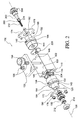
- the forward end portion of the valve stroke-adjustment stop member 202 has a split configuration, as can best be seen from FIGURE 2, whereby a plurality of circumferentially spaced, axially extending projections 278, which effectively form a recessed chamber within which the rear end portion of the coil spring 232 is seated, also define circumferentially spaced slots 280 therebetween.
- the portion of the valve stem 218, within which the forward end portion of the coil spring 232 is seated is provided with a plurality of circumferentially spaced apertures 282. Accordingly, it can be appreciated further that the hot melt adhesive or other thermoplastic material, disposed within gap 236, can enter slots 280, defined within the forward end portion of the valve stroke-adjustment stop member 202, so as to, in turn, enter the interior portion of the coil spring 232 from which it can then exit, through means of apertures 282, so as to enter the annular space 284 defined between the radially inner core portion 118 of the electromagnetic solenoid assembly 104 and the valve stem 218.
- valve stem 218 is provided with a spider-type structure whereby a plurality of circumferentially spaced leg members 286 of such spider structure effectively support the forward end portion of the valve stem 218 within the valve seat member 190 as well as guide the same during the reciprocal stroke movements of the valve stem 218 with respect to the valve seat member 190.
- a plurality of suitable seal or 0-ring members 290,292,294,296 are disposed at strategic locations within the solenoid-actuated hot melt adhesive or other thermoplastic material dispensing valve assembly 100 so as to effectively prevent the external leakage of any hot melt adhesive or other thermoplastic material out from the solenoid-actuated hot melt adhesive or other thermoplastic material dispensing valve assembly 100.
- the controller 155 is operated so as to effectively terminate electrical power to the electromagnetic coil 136 of the electro-magnetic solenoid assembly 106 and to provide electrical power to the electromagnetic coil 126 of the electro-magnetic solenoid assembly 104.
- Armature 224 will therefore be magnetically attracted toward the electromagnetic solenoid assembly 104, and the valve stem 218, having the ball valve 216 mounted thereon, will be moved from the rightwardly disposed position disclosed within FIGURE 5 to the leftwardly disposed position disclosed within FIGURE 6 whereby the ball valve 216 will be moved from its unseated or OPENED position to its seated or CLOSED position.
- the gap 234 will effectively be diminished from its aforenoted maximum dimension of, for example, 0.017 inches (0.017”), to its minimum dimension of, for example, 0.009 inches (0.009”), while at the same time the gap 236 will be correspondingly increased or expanded.
- gap 236 always being fluidically connected to the annular chamber 230 and the hot melt adhesive or other thermoplastic material inlet supply port 242
- hot melt adhesive or other thermoplastic material will tend to enter gap 236 thereby negating any tendency of the armature 226 to remain at its rightwardmost position adjacent, for example, electromagnetic coil 136 due to suction, capillary, or similar fluid adhesion properties developed between armature 226 and electromagnetic solenoid assembly 106.
- the hot melt adhesive or other thermoplastic material disposed within the gap 234, will effectively be squeezed or compressed.
- Such squeezing or compression of the fluid material effectively develops resistance forces tending to stop, decelerate, or dampen the leftward movement of the armature 224 toward its final position in order to permit the ball valve 216 to be disposed at its seated or CLOSED position.
- the provision of, for example, the annular cup-shaped recessed portion 256 within the armature 224 permits the hot melt adhesive or other thermoplastic material to be rapidly dispersed from the gap 234 whereby the armature 224 can in fact rapidly achieve its finalized position and without causing bounce of the ball valve 216 with respect to its valve seat 194.
- These controlled movements are desirable in order to achieve positive and accurate termination of the hot melt adhesive or other thermoplastic material dispensing, and as has also been noted hereinbefore, the coil spring 232 will then maintain the ball valve 216 seated upon its valve seat 194 once electrical power to the electromagnetic coil 126 has been terminated by the controller 155.
- FIGURE 7 a second embodiment of a new and improved dual inline solenoid-actuated hot melt adhesive or other thermoplastic material dispensing valve assembly, as has also been constructed in accordance with the principles and teachings of the present invention, is disclosed and is generally indicated by the reference character 300.
- the second embodiment dual inline solenoid-actuated hot melt adhesive or other thermoplastic material dispensing valve assembly 300 is conceptually similar to the first embodiment dual inline solenoid-actuated hot melt adhesive or other thermoplastic material dispensing valve assembly 100, and therefore a detailed description of the second embodiment dual inline solenoid-actuated hot melt adhesive or other thermoplastic material dispensing valve assembly 300 will be omitted in the interest of brevity, the description of the second embodiment dual inline solenoid-actuated hot melt adhesive or other thermoplastic material dispensing valve assembly 300 being substantially confined to the structural differences between the first and second embodiment dual in-line solenoid-actuated hot melt adhesive or other thermoplastic material dispensing valve assemblies 100,300.
- component parts of the second embodiment dual in-line solenoid-actuated hot melt adhesive or other thermoplastic material dispensing valve assembly 300 which correspond to similar component parts of the first embodiment dual in-line solenoid-actuated hot melt adhesive or other thermoplastic material dispensing valve assembly 100 will be designated by corresponding reference numbers except that they will be within the 300,400, and 500 series.
- one of the first structural differences existing between the first and second embodiment dual inline solenoid-actuated hot melt adhesive or other thermoplastic material dispensing valve assemblies 100,300 resides in the fact that, unlike the dispensing nozzle 212 comprising a separate component from the valve seat member 190, wherein the locknut 214 was required to secure the dispensing nozzle 212 upon the valve seat member 190, all in accordance with the principles and teachings of the structure comprising the first embodiment dual inline solenoid-actuated hot melt adhesive or other thermoplastic material dispensing valve assembly 100, the dispensing nozzle 412 of the second embodiment dual inline solenoid-actuated hot melt adhesive or other thermoplastic material dispensing valve assembly 300 has effectively been fabricated as an integral part of the valve seat member 390 thereby obviating the need for a separate locknut.
- valve seat 394 of the valve seat member 390 of the second embodiment dual inline solenoid-actuated hot melt adhesive or other thermoplastic material dispensing valve assembly 300 is disposed immediately upstream of the dispensing nozzle 412, and that the ball valve 216 has effectively been replaced by means of a conically configured needle valve 416.
- conically configured needle valve 416 in lieu of the ball valve 216, and more particularly, in view of the fact that the conically configured needle valve 416 is disposed immediately upstream of the dispensing nozzle 412 whereby the axially oriented bore 210 of the first embodiment dual inline solenoid-actuated hot melt adhesive or other thermoplastic material dispensing valve assembly 100 is able to be eliminated, hot melt adhesive or other thermoplastic material is not able to accumulate, for example, within the axially oriented bore 210 whereby "stringing" of the hot melt adhesive or other thermo-plastic material, subsequent to the movement of the conically configured needle valve member 416 to its CLOSED position, is effectively prevented.
- valve stroke-adjustment stop member 202 characteristic of the first embodiment dual inline solenoid-actuated hot melt adhesive or other thermoplastic material dispensing valve assembly 100 as illustrated within FIGURES 4 and 5 , comprised the plurality of circumferentially spaced, axially extending projections 278 which effectively formed a recessed chamber within which the rear end portion of the coil spring 232 is seated, and wherein further, circumferentially spaced slots 280 were defined between the axially extending projections 278 so as to define fluid flow paths for the hot melt adhesive or other thermoplastic material from fluid chamber 230 and gap 236.
- the axial length of the forwardly extending tubular portion 478 of the valve stroke-adjustment stop member 402 is substantially larger greater than the axial length defined by means of the axially extending projections 278 of the valve stroke-adjustment stop member 202, and accordingly, a greater axially extending portion of the coil spring 432 will be seated or accommodated within the internal bore of the forwardly extending tubular portion 478 of the valve stroke-adjustment stop member 402.
- a plurality, for example, three, of circumferentially spaced, axially extending grooves 480 are defined within outer surface portions of the tubular portion 478, and that a plurality, for example, three, of circumferentially spaced, radially extending bores 582 are defined within the valve stroke-adjustment stop member 402 so as to be respectively fluidically connected at first end portions thereof to the plurality of axially extending grooves 480.
- a first axially extending fluid passageway 584 is effectively defined within a first axially extending bore formed within the valve stroke-adjustment stop member 402 so as to fluidically connect second end portions of the plurality of radially extending bores 582 with the bore within which the coil spring 432 is disposed, and a threaded set screw or plug 586 is disposed within the valve stroke-adjustment stop member 402 so as to close off the rear end portion of the bore within which the axially extending fluid passageway 584 is defined.
- a second axially extending fluid passageway 588 is effectively defined within a second axially extending bore formed within the valve stem 418, and a plurality of circumferentially spaced apertures 482 are also defined within the valve stem 418 so as to fluidically connect the second axially extending fluid passageway 588 with the annular space 484 effectively surrounding the valve stem 418.
- hot melt adhesive or other thermoplastic material disposed within the gap 436, can flow through the plurality of axially extending grooves 480, into the radially extending bores 582, into the first axially extending fluid passageway 584, through the interior portion of the coil spring 432, through the second axially extending fluid passageway 588, out through the plurality of apertures 482, and into the annular space 484 surrounding the valve stem 418 so as to effectively combine with the other hot melt adhesive or other thermoplastic material fluid flows, as has been previously described in connection with the first embodiment dual inline solenoid-actuated hot melt adhesive or other thermo-plastic material dispensing valve assembly 100, whereby such fluid flows can then be conducted into the internal chamber 488 defined within the valve seat member 390 such that the hot melt adhesive or other thermoplastic material can be discharged from the dispensing nozzle 412.
- thermoplastic material dispensing valve assembly 300 A last structural difference between the second embodiment dual inline solenoid-actuated hot melt adhesive or other thermoplastic material dispensing valve assembly 300 and the first embodiment dual inline solenoid-actuated hot melt adhesive or other thermo-plastic material dispensing valve assembly 100 resides in a modification of the structure comprising the electromagnetic solenoid assemblies 104,106 and the end plates 172,174 utilized in conjunction with the electromagnetic solenoid assemblies 104,106.
- the radially outwardly extending annular flange portions 120,130 have effectively been combined with the end plates 172,174 so as to effectively form new end wall members 590,592 within the second embodiment dual inline solenoid-actuated hot melt adhesive or other thermoplastic material dispensing valve assembly 300, and in addition, it is seen that the new end wall members 590,592 also integrally connect together the radially inner, axially extending annular or tubular core portions 318,328 and the radially outer annular cover members or portions 322,332 into single or one-piece
- the pair of electromagnetic solenoid assemblies can rapidly and assuredly control the reciprocal movements of the valve stem, and the valve member attached thereto, in order to rapidly and assuredly move the ball valve between its unseated or OPENED position and its seated or CLOSED position such that the dispensing valve assembly can control the discharge of the hot melt adhesive or other thermoplastic material through a hot melt adhesive or other thermoplastic material dispensing nozzle.
- a coil spring also biases the valve stem and the valve member toward the seated or CLOSED position such that when both of the electromagnetic solenoid assemblies are de-energized, the coil spring is just sufficiently strong so as to simply maintain the valve member at its seated or CLOSED position upon the valve seat.
- the biasing force of the coil spring mechanism is relatively small since it is not effectively utilized in connection with the movement of the valve stem, and the valve member, from the unseated or OPENED position to the seated or CLOSED position, so as not to adversely affect the movement of the armature and the valve stem when the valve member is to be moved from its seated or CLOSED position to its unseated or OPENED position.
- the positions of the armatures with respect to the electromagnetic solenoid assemblies can be accurately adjusted, as can the stroke movement of the valve stem and the valve member between the respective seated or CLOSED position and the unseated or OPENED position, so as to effectively optimize the operational cycles of the hot melt adhesive or other thermoplastic material dispensing valve assembly.
Landscapes
- Engineering & Computer Science (AREA)
- General Engineering & Computer Science (AREA)
- Mechanical Engineering (AREA)
- Physics & Mathematics (AREA)
- Electromagnetism (AREA)
- Magnetically Actuated Valves (AREA)
Abstract
Description
- The present invention relates generally to dispensing valve assemblies, and more particularly to a new and improved dual inline solenoid-actuated hot melt adhesive or other thermoplastic material dispensing valve assembly which is actuated by means of a pair of oppositely disposed inline electromagnetic solenoid assemblies which respectively and alternatively act upon a pair of armatures which are fixedly mounted upon a valve stem, upon which is fixedly attached a valve member, so as to rapidly and assuredly control the reciprocal movements of the valve stem, and the valve member attached thereto, in order to rapidly and assuredly move the valve member between its unseated or OPENED position and its seated or CLOSED position such that the dispensing valve assembly can control the discharge of hot melt adhesive or other thermoplastic material through a hot melt adhesive or other thermoplastic material dispensing nozzle. A coil spring also biases the valve stem and the valve member toward the seated or CLOSED position such that when both of the electro-magnetic solenoid assemblies are de-energized, the coil spring maintains the valve member at its seated or CLOSED position upon the valve seat. In addition, the positions of the armatures with respect to the electromagnetic solenoid assemblies can be accurately adjusted, as can the stroke movement of the valve stem and the valve member between the respective seated or CLOSED position and the unseated or OPENED position, so as to effectively optimize the operational cycles of the hot melt adhesive or other thermoplastic dispensing valve assembly.
- Conventional, hot melt adhesive dispensing valve assemblies are of course well-known in the art. One example of a pneumatically-controlled hot melt adhesive dispensing valve assembly is disclosed within United States Patent
6,315,168 which issued to Bolyard, Jr. et al. on November 13, 2001 . While this dispensing valve assembly is quite satisfactory from an operational point of view, a special sealing cartridge for the hot melt adhesive and control air fluids is required. In addition, the control valve assembly requires special maintenance procedures to be implemented, and the overall assembly is noisy. Electromagnetic solenoid-controlled dispensing valve assemblies are in fact also known in the art, however, they suffer from several different operational drawbacks. For example, one type of conventional electromagnetic solenoid-controlled dispensing valve assembly comprises the use of a single electromagnetic solenoid assembly for moving the dispensing valve assembly from its seated or CLOSED position to its unseated or OPENED position, while a coil spring mechanism is utilized to move the dispensing valve assembly from its unseated or OPENED position back to its seated or CLOSED position. As can readily be appreciated, however, the use of the coil spring mechanism as the sole means for achieving the return stroke or movement of the dispensing valve assembly from its unseated or OPENED position back to its seated or CLOSED position is problematic for several reasons. - For example, in order to ensure that the movement of the dispensing valve assembly from its unseated or OPENED position back to its seated or CLOSED position is in fact achieved in a relatively quick and responsive manner in order to, in turn, ensure that the discharge or dispensing of the hot melt adhesive material, from the nozzle portion operatively associated with the dispensing valve assembly, is terminated at a substantially precise point in time and without exhibiting stringing of the hot melt adhesive material, the biasing force of the coil spring mechanism must necessarily be significant or substantially large. Conversely, however, if the coil spring mechanism does in fact have a significantly large biasing force oriented in the valve seating or CLOSED direction, then the stroke or movement of the dispensing valve assembly will be relatively slow in that the movement or stroke of the dispensing valve assembly must overcome the significantly large biasing force of the coil spring mechanism. Alternatively, the single electromagnetic solenoid assembly must be fabricated so as to be relatively large in size in order to generate a sufficiently large electromagnetic force which can easily, readily, and quickly overcome the aforenoted substantially large biasing force of the coil spring mechanism in order to ensure the precise and rapid stroke or movement of the valve stem, and the ball valve mounted thereon, when the ball valve is to be moved from its seated or CLOSED position to its unseated or OPENED position.
- A need therefore exists in the art for a new and improved solenoid-actuated hot melt adhesive or other thermo-plastic material dispensing valve assembly wherein the operational drawbacks characteristic of the conventional, prior art solenoid-actuated hot melt adhesive dispensing valve assemblies can effectively be overcome. More particularly, a need exists in the art for a new and improved solenoid-actuated hot melt adhesive dispensing valve assembly wherein the movements or strokes of the valve stem and the ball valve mounted thereon, from the seated or CLOSED position to the unseated or OPENED position, as well as from the unseated or OPENED position to the seated or CLOSED position, can be assuredly and quickly achieved without the need for a relatively large coil spring mechanism for generating a relatively large valve closure biasing force, and without the need for a relatively large electromagnetic solenoid assembly for generating a relatively large valve opening force for effectively overcoming the relatively large valve closure biasing force of the relatively large coil spring mechanism.
- The foregoing and other objectives are achieved in accordance with the teachings and principles of the present invention through the provision of a new and improved dual inline solenoid-actuated hot melt adhesive or other thermo-plastic material dispensing valve assembly which is actuated by means of a pair of oppositely disposed inline electromagnetic solenoid assemblies which respectively and alternatively act upon a pair of armatures which are fixedly mounted up-on a valve stem upon which is fixedly attached a valve member. In this manner, the pair of electromagnetic solenoid assemblies can rapidly and assuredly control the reciprocal movements of the valve stem, and the valve member attached thereto, in order to rapidly and assuredly move the valve member between its unseated or OPENED position and its seated or CLOSED position such that the dispensing valve assembly can control the discharge of hot melt adhesive or other thermoplastic material through a hot melt adhesive or other thermoplastic material dispensing nozzle.
- A coil spring also biases the valve stem and the valve member toward the seated or CLOSED position such that when both of the electromagnetic solenoid assemblies are de-energized, the coil spring is just sufficiently strong so as to simply maintain the valve member at its seated or CLOSED position upon the valve seat. However, the biasing force of the coil spring mechanism is relatively small since it is not effectively utilized in connection with the movement of the valve stem, and the valve member, from the unseated or OPENED position to the seated or CLOSED position, so as not to adversely affect the movement of the armature and the valve stem when the valve member is to be moved from its seated or CLOSED position to its unseated or OPENED position. In addition, the positions of the armatures with respect to the electromagnetic solenoid assemblies can be accurately adjusted, as can the stroke movement of the valve stem and the valve member between the respective seated or CLOSED position and the unseated or OPENED position, so as to effectively optimize the operational cycles of the hot melt adhesive or other thermoplastic material dispensing valve assembly.
- Various other features and attendant advantages of the present invention will be more fully appreciated from the following detailed description when considered in connection with the accompanying drawings in which like reference characters designate like or corresponding parts throughout the several views, and wherein:
-
FIGURE 1 is a perspective view of a first embodiment of a new and improved dual inline solenoid-actuated hot melt adhesive or other thermoplastic material dispensing valve assembly as constructed in accordance with the principles and teachings of the present invention and showing the same in its assembled state; -
FIGURE 2 is an exploded perspective view of the new and improved dual inline solenoid-actuated hot melt adhesive or other thermoplastic material dispensing valve assembly as illustrated withinFIGURE 1 and showing the variously cooperative component parts thereof; -
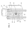
FIGURE 3 is a cross-sectional view of the new and improved dual inline solenoid-actuated hot melt adhesive or other thermoplastic material dispensing valve assembly as illustrated withinFIGURE 1 and as taken along lines 3-3 ofFIGURE 1 ; -
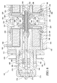
FIGURE 4 is a cross-sectional view of the new and improved dual inline solenoid-actuated hot melt adhesive or other thermoplastic material dispensing valve assembly as illustrated withinFIGURE 1 and as taken along lines 4-4 ofFIGURE 1 , wherein the dispensing valve is illustrated at its seated or CLOSED position; -
FIGURE 5 is an enlarged partial cross-sectional view, similar to that ofFIGURE 4 , wherein, however, the cover member has been removed and the dispensing valve is illustrated at its unseated or OPENED position so as to illustrate the flow of the hot melt adhesive or other thermoplastic material internally within the dispensing valve assembly from the inlet port to the dispensing nozzle; -
FIGURE 6 is an enlarged partial cross-sectional view similar to that ofFIGURE 5 , wherein, however, the dispensing valve is again illustrated at its SEATED or CLOSED position; and -
FIGURE 7 is a partial cross-sectional view, similar to that ofFIGURE 5 , wherein, however, a second embodiment of a new and improved dual inline solenoid-actuated hot melt adhesive or other thermoplastic material dispensing valve assembly, as constructed in accordance with the principles and teachings of the present invention, is illustrated. - Referring now to the drawings, and more particularly initially to
FIGURES 1 ,2 , and4 thereof, a new and improved dual inline solenoid-actuated hot melt adhesive or other thermoplastic material dispensing valve assembly, as has been constructed in accordance with the principles and teachings of the present invention, is disclosed and is generally indicated by thereference character 100. More particularly, it is seen that the new and improved dual in-line solenoid-actuated hot melt adhesive or other thermoplastic materialdispensing valve assembly 100 comprises ahousing 102 within which a pair of oppositely disposed electromagnetic solenoid assemblies 104,106 are adapted to be mounted so as to effectively be annularly disposed around thelongitudinal axis 108 of the dual inline solenoid-actuated hot melt adhesive or other thermoplastic materialdispensing valve assembly 100. As can best be appreciated fromFIGURES 2 and4 , thehousing 102 is provided with a pair of oppositely disposed stepped bores 110,112 which extend axially inwardly into thehousing 102 from a pair of oppositely disposed external end faces or wall members 114,116, and it is to be appreciated that substantial portions of the electromagnetic solenoid assemblies 104,106 are adapted to be disposed within the aforenoted stepped bores 110,112 defined within thehousing 102. As can best be appreciated fromFIGURE 4 , each one of the electro-magnetic solenoid assemblies 104,106 effectively comprises a three-piece structure, although it is possible that each one of the electromagnetic solenoid assemblies 104,106 could also effectively comprise a two-piece structure, as will be discussed shortly hereinafter. - More particularly, it is seen, for example, that the
electromagnetic solenoid assembly 104 comprises a radially inner, axially extending annular ortubular core portion 118, a radially outwardly extending,annular flange portion 120 integrally connected to the radially inner, axially extendingannular core portion 118, and a radially outerannular cover member 122 disposed around and effectively covering both the radially inner, axially extendingannular core portion 118 and the radially outwardly extending,annular flange portion 120 so as to define with the radially inner, axially extendingannular core portion 118 and the radially outwardly extending,annular flange portion 120 anannular pocket 124, which is open upon one end portion thereof, within which is disposed an annularelectromagnetic coil 126. In a similar manner, theelectromagnetic solenoid assembly 106 comprises a radially inner, axially extendingannular core portion 128, a radially outwardly extending,annular flange portion 130 integrally connected to the radially inner, axially extendingannular core portion 128, and a radially outerannular cover member 132 disposed around and effectively covering both the radially inner, axially extending annular ortubular core portion 128 and the radially outwardly extending,annular flange portion 130 so as to define with the radially inner, axially extendingannular core portion 128 and the radially outwardly extending,annular flange portion 130 anannular pocket 134, which is open upon one end portion thereof, within which is disposed an annularelectromagnetic coil 136. The electromagnetic coils 126,136 are potted within the annular pockets 124,134 so as to effectively seal the same against the ingress of any hot melt adhesive material, and it is seen that the free end portions or terminal members 138,140 of the electromagnetic coils 126,136 extend radially through first slots 142,144 respectively defined within the annular cover members 122,132 and through second slots 146,148 respectively defined withinupper wall member 150 of thevalve assembly housing 102. - Alternatively, the free end portions or terminal members 138,140 of the electromagnetic coils 126,136 can initially be routed axially and then radially. A
cover member 152, having an upstandingelectrical connector 154 integrally formed therewith and adapted to be electrically connected to a power supply andcontroller 155, is adapted to not only be fixedly secured atop the housing by means of a pair ofbolt fasteners 156, but in addition, thebolt fasteners 156 secure the entire hot melt adhesive or other thermoplastic materialdispensing valve assembly 100 atop a hot melt adhesive or other thermoplastic material supply unit, not shown, from which hot melt adhesive or other thermoplastic material is supplied into the hot melt adhesive or other thermoplasticdispensing valve assembly 100 as will be more fully disclosed hereinafter. It is further seen that thecover member 152 has aninternal conduit 158 defined therein within which electrical wiring, interconnecting the pair of free end portions or terminal members 138,140 of the electromagnetic coils 126,136 to theelectrical connector 154, can be routed. As has been noted, in lieu of the core portions 118,128 being separate structural pieces with respect to the annular cover members 122,132 wherein the core portions 118,128 would, for example, be press-fitted or otherwise bonded to the annular cover members 122,132, the core portions 118,128 and the annular cover members 122,132 could respectively be fabricated as single integral components. - Continuing further, and in connection with the actual installation of the electromagnetic solenoid assemblies 104,106 within the stepped bores 110,112 of the
housing 102, it is seen that the stepped bores 110,112 are respectively provided with annular counterbored regions 160,162 which extend axially inwardly into thehousing 102 from the pair of oppositely disposed external end faces orwall members annular ridge portions FIGURE 4 , when the electromagnetic solenoid assemblies 104,106 are inserted within the hot melt adhesive dispensingvalve assembly housing 102, they will be precisely located or positioned within thehousing 102. Still yet further, in order to fixedly retain the electromagnetic solenoid assemblies 104,106 within the bores 110,112 of thehousing 102, a pair of end plates 172,174 are adapted to engage the radially outwardly extending flanged portions 120,130 of the electromagnetic solenoid assemblies 104,106, the end plates 172,174 being fixed onto the end faces or wall members 114,116 of thehousing 102 by means of a plurality of bolt fasteners 176,178. In addition, it is also seen that each one of the end plates 172,174 has a central aperture 180,182 defined therein in order to permit axially outwardly extending tubular or annular portions 184,186 of the electromagnetic solenoid assemblies 104,106 to respectively project therethrough as can best be seen or appreciated fromFIGURES 2 and4 . Alternatively,end plate 172, radially outwardly extendingflanged portion 120, andannular cover member 122 may comprise an integrated or single-piece structure, and similarly forend plate 174, radially outwardly extendingflanged portion 130, andannular cover member 132. - More particularly, it is seen that the free or distal annular end section of the
annular portion 184 of theelectromagnetic solenoid assembly 104 is internally threaded as at 188, and a tubular or annularvalve seat member 190 is externally threaded as at 192. Thevalve seat member 190 comprises avalve seat 194, andbores 196 are provided within the external end face of thevalve seat member 190 for receiving, for example, a spanner wrench or similar rotating tool so as to effectively adjust the axial position of thevalve seat member 190 within theannular portion 184 of theelectromagnetic solenoid assembly 104. In addition, alocknut 198 is also threadedly engaged upon the externally threadedportion 192 of thevalve seat member 190 and is adapted to engage the external annular end face of theannular portion 184 of theelectromagnetic solenoid assembly 104 so as to fixedly lock thevalve seat member 190 at a particular axially adjusted position with respect to theelectromagnetic solenoid assembly 104. In a similar manner, it is seen that the free or distal annular end section of theannular portion 186 is internally threaded as at 200, and a valve stroke-adjustment stop member 202 is externally threaded as at 204. Bores 206 are provided within the external end face of the valve stroke-adjustment stop member 202 for receiving, for example, a spanner wrench or similar rotating tool so as to effectively adjust the axial position of the valve stroke-adjustment stop member 202 within theannular portion 186 of theelectromagnetic solenoid assembly 106 and alocknut 208 is also threadedly engaged upon the externally threadedportion 204 of the valve stroke-adjustment stop member 202 so as to engage the external annular end face of theannular portion 186 of theelectromagnetic solenoid assembly 106 and thereby fixedly lock the valve stroke-adjustment stop member 202 at a particular axially adjusted position with respect to theelectromagnetic solenoid assembly 106. - Continuing further, the
valve seat member 190 is provided with an axially extendingbore 210, and a dispensingnozzle 212 is adapted to be fixedly mounted upon thevalve seat member 190 by means of an internally threadedlocknut 214 which is threadedly engaged upon the externally threadedportion 192 of thevalve seat member 190. Alternatively, the dispensingnozzle 212 and thevalve seat member 190 can comprise a one-piece integral structure whereby thelocknut 214 can effectively be eliminated. Aball valve 216 is integrally mounted upon a forward or downstream end portion of avalve stem 218, and it is seen that thevalve stem 218 extends axially within thevalve seat member 190 and the annular ortubular portion 118 of theelectromagnetic solenoid assembly 104. It is also seen that the rearward or upstream end portion of thevalve stem 218 is externally threaded, and a pair of radially outwardly extending annular armatures 224,226, respectively disposed within a pair of radially oriented annular chambers 228,230 defined withinhousing 102, are internally threaded so as to be threadedly engaged upon the upstream or rearward end portion of thevalve stem 218 as at 220,222. Other means can of course be implemented for fixedly securing the armatures 224,226 upon thevalve stem 218, such as, for example, by press-fitting or the like. Still further, it is also seen that the rearward or upstream end portion of thevalve stem 218 is tubular, as is the forward end portion of the valve stroke-adjustment stop member 202, and in this manner, acoil spring 232 is able to be accommodated within both structures or components. It is to be noted that in lieu of the axially separatedannular armatures valve stem 218, a single annular armature, having, for example, a substantially H-shaped cross-sectional configuration, could be utilized and fixedly secured upon thevalve stem 218, or alternatively still further, thearmatures valve stem 218. - While a complete cyclical operation of the new and improved dual inline solenoid-actuated hot melt adhesive or other thermoplastic
dispensing valve assembly 100 will be described hereinafter, it is to be appreciated at this point in time that when theelectromagnetic coil 126 of the electro-magnetic solenoid assembly 104 is energized, thearmature 224 will be magnetically attracted toward theelectromagnetic coil 126 so as to effectively move thevalve stem 218 toward the left as viewed inFIGURE 4 whereby theball valve 216 will be seated upon thevalve seat 194. Alternatively, when theelectromagnetic coil 136 of theelectromagnetic solenoid assembly 106 is energized, thearmature 226 will be magnetically attracted toward theelectromagnetic coil 136 so as to effectively move thevalve stem 218 toward the right as viewed inFIGURE 4 , against the biasing force ofcoil spring 232 which will be compressed between thevalve stem 218 and the valve stroke-adjustment stop member 202, whereby theball valve 216 will be unseated from thevalve seat 194. Subsequently, when theelectromagnetic coil 136 of theelectromagnetic solenoid assembly 106 is de-energized, and the electro-magnetic coil 126 of theelectromagnetic solenoid assembly 104 is re-energized, theball valve 216 will again be seated upon thevalve seat 194, and still further, upon de-energization of theelectromagnetic coil 126 of theelectromagnetic solenoid assembly 104, thecoil spring 232 is sufficiently strong so as to maintain theball valve 216 seated upon thevalve seat 194. It can therefore be appreciated that while the electromagnetic coils 126,136 are utilized so as ensure quick and rapid stroke movements of thevalve stem 218 and theball valve 216 with respect to the seated or CLOSED position and the unseated or OPEN position, theelectromagnetic coil 126 need not be energized to maintain theball valve 216 at its seated or CLOSED position. It is to be noted that the aforenoted energization, de-energization, and re-energization operative cycles for the electromagnetic solenoid assemblies 104,106 are of course controlled by means of the aforenoted power supply andcontroller 155. - With reference still being made to
FIGURE 4 , and with additional reference being made toFIGURES 5 and6 , it is to be appreciated that when the new and improved dual in-line solenoid-actuated hot melt adhesive dispensingvalve assembly 100 is initially assembled, as illustrated withinFIGURES 4 and 6, first and second predetermined gaps or spaces 234,236 are respectively defined between the right end face portion of theelectromagnetic solenoid assembly 104 and thearmature 224, and between the left end face portion of theelectromagnetic solenoid assembly 106 and thearmature 226, while a third predetermined gap orspace 238 is defined between the rearward or upstream end portion of thevalve stem 218 and the forward end portion of the valve stroke-adjustment stop member 202. More particularly, the first and second predetermined gaps or spaces 234,236 can be within the range of, for example, 0.008-0.030 inches (0.008-0.030"), while the third predetermined gap orspace 238 can be within the range of, for example, 0.008-0.015 inches (0.008-0.015"). - However, when the
ball valve 216 is in fact seated upon thevalve seat 194 as illustrated withinFIGURES 4 and6 , it is preferred, for example, that the firstpredetermined gap 234 will be approximately 0.009 inches (0.009"), the secondpredetermined gap 236 will be approximately 0.017 inches (0.017"), and the thirdpredetermined gap 238, which effectively defines the movement stroke of thevalve stem 218 and theball valve 216 with respect to thevalve seat 194, will be approximately 0.008 inches (0.008"). When theelectromagnetic coil 136 of theelectromagnetic solenoid assembly 106 is energized so as to effectively magnetically attract thearmature 226 thereto and thereby unseat theball valve 216 from its seated or CLOSED position to its unseated or OPEN position as illustrated withinFIGURE 5 , the first predetermined gap orspace 234 will be now be approximately 0.017 inches (0.017"), the second predetermined gap orspace 236 will now be approximately 0.009 inches (0.009"), and the third predetermined gap orspace 238 will now be zero as a result of the right end face portion of thevalve stem 218 being disposed in contact with, and abutting, the left end face portion of the valve stroke-adjustment stop member 202. - The aforenoted predetermined gaps or
spaces 234, 236,238 may in fact be precisely defined in view of the fact that various parameters are known. For example, since the precise location of theelectromagnetic solenoid assembly 104 within thehousing 102 is known, and knowing the fact that theleft armature 224 is threadedly located at a precise position upon the rearward or upstream end portion of thevalve stem 218, and knowing, still further, the thread pitch of the threads defined between the internally threadedportion 188 of theannular portion 184 of theelectromagnetic solenoid assembly 104, and the externally threadedportion 192 of the annularvalve seat member 190, the axial location of the annularvalve seat member 190 within theelectromagnetic solenoid assembly 104 can be precisely adjusted. Accordingly, the disposition of theball valve 216, seated upon thevalve seat 194, and the disposition of thevalve stem 218, having thearmature 224 fixedly disposed thereon, will be predetermined so as to in fact predetermine the first gap orspace 234. In a similar manner, since theright armature 226 is then threadedly located at a precise position upon the rearward or upstream end portion of thevalve stem 218, and since the location of theelectromagnetic solenoid assembly 106 within thehousing 102 is known, predetermined, or precisely located, the second gap orspace 236 is likewise precisely predetermined. Still further, since the thread pitch defined between the internally threadedportion 200 of the annular end section of theannular portion 186 of theelectromagnetic solenoid assembly 106 and the externally threadedportion 204 of the valve stroke-adjustment stop member 202 is also known, the axial location of the valve stroke-adjustment stop member 202 within theelectromagnetic solenoid assembly 106 can be precisely adjusted so as to define the third space orgap 238, and thereby the movement stroke of thevalve stem 218 and theball valve 216 between their seated or CLOSED positions and their unseated or OPENED positions. - With reference now being made to
FIGURES 3 ,5 , and6 , it will be recalled that the hot melt adhesive dispensingvalve assembly 100 is adapted to be fixedly secured atop a hot melt adhesive or other thermoplastic material supply unit, not shown, by means of thebolt fasteners 156 such that a supply of the hot melt adhesive or other thermoplastic material can be supplied into the hot melt adhesive or other thermoplastic material dispensingvalve assembly 100. Accordingly, it is seen that thebottom wall member 240 is provided with a substantially centrally located hot melt adhesive or other thermoplastic material inlet supply port orpassageway 242 which extends vertically upwardly into thehousing 102, and first and second, upper and lower arcuately configured passageways 244,246 are defined within thehousing 102 so as to be respectively interposed between theupper wall member 150 of thehousing 102 and the rearward or upstream end portion of thevalve stem 218, and between thelower wall member 240 of thehousing 102 and the rearward or upstream end portion of thevalve stem 218. In addition, it is also seen that the upper and lower arcuately configured passageways 244,246 have predetermined axial extents so as to fluidically interconnect the fluid chambers 228,230 within which the armatures 224,226 are disposed, and still further, anannular passageway 248 is defined within thehousing 102 so as to be annularly disposed around the rearward or upstream end portion of thevalve stem 218. - Auxiliary fluid passageways 250,252, which are effectively inward extensions of the inlet supply port or
passageway 242, are also provided within thehousing 102 so as to respectively fluidically interconnect the lowerarcuate passageway 246 to theannular passageway 248, and theannular passageway 248 to the upperarcuate passageway 244. Still yet further, it is seen that thearmature 224 is provided with a plurality of circumferentially spaced, axially oriented bores 254, and an annular cup-shaped or recessedportion 256 which is defined within the face of thearmature 224 which is disposed towardelectromagnetic solenoid assembly 104 such that theannular portion 256 of thearmature 224 is effectively radially aligned with theelectromagnetic coil 126. In a similar manner, thearmature 226 is provided with a plurality of circumferentially spaced, axially oriented bores 258, and an annular cup-shaped or recessedportion 260 which is defined within the face of thearmature 226 which is disposed towardelectromagnetic solenoid assembly 106 such that theannular portion 260 of thearmature 224 is effectively radially aligned with theelectromagnetic coil 136. In this manner, it can be appreciated that as a result of the provision of the various fluid passageways 242-250, as well as thebores armatures - Continuing still further, and with reference still being made to
FIGURES 5 and6 , it is also seen that as a result of the aforenoted structure comprising each one of the electromagnetic solenoid assemblies 104,106, each one of the electromagnetic armatures 224,226, and the relative disposition of the armatures 224,226 with respect to the electromagnetic solenoid assemblies 104,106, the electromagnetic interaction defined between the electromagnetic solenoid assemblies 104,106 and the armatures 224,226 can readily be appreciated or understood. More particularly, it is seen that the radially inner, axially extending annular ortubular core portion 118 of theelectromagnetic solenoid assembly 104 comprises a radially innerannular end face 262, and that the radially outerannular cover member 122 of theelectromagnetic solenoid assembly 104 comprises a radially outerannular end face 264. In a similar manner, the radially inner, axially extending annular ortubular core portion 128 of theelectromagnetic solenoid assembly 106 comprises a radially innerannular end face 266, and that the radially outerannular cover member 132 of theelectromagnetic solenoid assembly 106 comprises a radially outerannular end face 268. Correspondingly, it is seen that the radially inner annular portion of thearmature 224 comprises a radially innnerannular end face 270, and that the radially outer annular portion of thearmature 224 comprises a radially outerannular end face 272. In a similar manner, the radially inner annular portion of thearmature 226 comprises a radially innerannular end face 274, and that the radially outer annular portion of thearmature 226 comprises a radially outerannular end face 276. - It is also to be noted that while the radial thicknesses of the radially inner, axially extending annular or tubular core portions 118,128 of the electromagnetic solenoid assemblies 104,106 and those of their
annular end face annular cover members longitudinal axis 108 of the hot melt adhesive dispensingvalve assembly 100, it being remembered that the surface area of a circular geometrical figure is directly proportional to the radius squared. - Similar surface area characteristics are likewise applicable to, or true of, the radially inner
annular end face 270 of the radially inner annular portion of thearmature 224 with respect to the radially outerannular end face 272 of the radially outer annular portion of thearmature 224, and similarly with respect to the radially innerannular end face 274 of the radially inner annular portion of thearmature 226 with respect to the radially outerannular end face 276 of the radially outer annular portion of thearmature 226. In addition, the radial thicknesses and surface areas of the radially inner annular end faces 262,266 of the radially inner, axially extending annular or tubular core portions 118,128 are respectively substantially equal to the radial thicknesses and surface areas of the radially inner annular end faces 270,274 of the radially inner annular portions of the armatures 224,226, and similarly, the radial thicknesses and surface areas of the radially outer annular end faces 264,268 of the radially outer annular cover members 122,132 are respectively substantially equal to the radial thicknesses and surface areas of the radially outer annular end faces 272,276 of the radially outer annular portions of the armatures 224,226. Still yet further, it is also noted that the armatures 224,226 comprise radially outward tapered structures such that the axial thicknesses of the armatures 224,226 progressively decrease as one proceeds in the radially outward direction. In this manner, the flux density characteristics of the armatures 224,226 are substantially constant throughout their structures. - Having described substantially all of the pertinent structure characteristic of the new and improved dual inline solenoid-actuated hot melt adhesive or other thermoplastic material dispensing
valve assembly 100, the operation of the new and improved dual inline solenoid-actuated hot melt adhesive or other thermoplastic material dispensingvalve assembly 100 will now be described. With reference therefore being made toFIGURES 5 and6 , it is seen that prior to the initiation of a hot melt adhesive or other thermoplastic material dispensing cycle, the various components parts of the new and improved dual inline solenoid-actuated hot melt adhesive or other thermoplastic material dispensingvalve assembly 100 are at their respective positions illustrated withinFIGURE 6 , that is, for example, both of the electro-magnetic coils 126,136 of the electromagnetic solenoid assemblies 104,106 have been de-energized and theball valve 216 is seated upon itsvalve seat 194 under the biasing force of thecoil spring 232. - When it is desired to initiate a hot melt adhesive or other thermoplastic material dispensing cycle,
electromagnetic coil 136 ofelectromagnetic solenoid assembly 106 will be energized, and accordingly, as a result of the magnetic attraction of thearmature 226 to theelectromagnetic solenoid assembly 106, as developed by means of the magnetic flux flowing, for example, through the axially extending annular ortubular core portion 128 of theelectromagnetic solenoid assembly 106, throughgap 236, througharmature 226, back throughgap 236, through radially outerannular cover member 132, and through radially outwardly extending,annular flange portion 130,armature 226 will be moved toward the right, as viewed withinFIGURES 5 and6 , whereby thevalve stem 218 will likewise be moved toward the right, against the biasing force ofcoil spring 232, until the upstream or rearward end portion of the valve stem 218 encounters the forward end portion of the valve stroke-adjustment stop member 202. As a result of the rightward movement of thevalve stem 218, theball valve 216, mounted uponvalve stem 218, will be moved to its unseated or OPENED position with respect to itsvalve seat 194 whereby hot melt adhesive or other thermoplastic material can be discharged and dispensed from dispensingnozzle 212, such a dispensing operation or cycle of the hot melt adhesive or other thermoplastic material from dispensingnozzle 212 continuing as long as theelectromagnetic coil 136 of theelectromagnetic solenoid assembly 106 is maintained in its energized state. - More particularly, as can best be appreciated from
FIGURE 5 , when in fact theball valve 216 has been moved to its unseated or OPENED position with respect to thevalve seat 194, as has been previously noted, hot melt adhesive or other thermoplastic material, being supplied into the new and improved dual inline solenoid-actuated hot melt adhesive or other thermoplastic material dispensingvalve assembly 100 through means of inlet port orpassageway 242, will flow intolower passageway 246 and from there will essentially be split into three fluid flows. The first fluid flow will enter the lower end portion of thechamber 228, flow around the lower end portion of thearmature 224, and enter the lower end portion of thegap 234. The second fluid flow will continue upwardly through fluid passageways 250,248,252,244 and will, in turn, be split so as to not only enter the upper end portion of thechamber 228 so as to flow around the upper end portion of thearmature 224, as well as to flow through thebores 254 defined within thearmature 224 so as to enter the upper end portion of thegap 234, but, in addition, will also flow into the upper end portion of thechamber 230. The third fluid flow will enter the lower end portion of thechamber 230 so as to not only flow around the lower end portion of thearmature 226, but, in addition, will flow thebores 258 defined within thearmature 226 so as to enter the cup-shaped recessedportion 260 of thearmature 226 as well as the lower end portion of thegap 236. It is additionally seen that the forward end portion of the valve stroke-adjustment stop member 202 has a split configuration, as can best be seen fromFIGURE 2, whereby a plurality of circumferentially spaced, axially extendingprojections 278, which effectively form a recessed chamber within which the rear end portion of thecoil spring 232 is seated, also define circumferentially spacedslots 280 therebetween. - In addition, it is also seen the portion of the
valve stem 218, within which the forward end portion of thecoil spring 232 is seated, is provided with a plurality of circumferentially spacedapertures 282. Accordingly, it can be appreciated further that the hot melt adhesive or other thermoplastic material, disposed withingap 236, can enterslots 280, defined within the forward end portion of the valve stroke-adjustment stop member 202, so as to, in turn, enter the interior portion of thecoil spring 232 from which it can then exit, through means ofapertures 282, so as to enter theannular space 284 defined between the radiallyinner core portion 118 of theelectromagnetic solenoid assembly 104 and thevalve stem 218. In a similar manner, hot melt adhesive or other thermoplastic material, disposed withingap 234, will also enter theannular space 284 whereby the combined fluid flows will proceed toward the dispensingnozzle 212. It is lastly noted that the forward end portion of thevalve stem 218 is provided with a spider-type structure whereby a plurality of circumferentially spacedleg members 286 of such spider structure effectively support the forward end portion of thevalve stem 218 within thevalve seat member 190 as well as guide the same during the reciprocal stroke movements of thevalve stem 218 with respect to thevalve seat member 190. -
Spaces 288, defined between theleg members 286 and within the internal chamber of thevalve seat member 190 in which the forward end portion of thevalve stem 218 is disposed, permit the aforenoted combined fluid flow of the hot melt adhesive or other thermoplastic material to flow past the same and into the axially extending discharge bore 210 of thevalve seat member 190. It is to be noted that the provision of the various aforenoted split fluid flows throughout the structure of the new and improved dual inline solenoid-actuated hot melt adhesive or other thermoplastic material dispensingvalve assembly 100 prevents stagnation of the hot melt adhesive or other thermoplastic material whereby, in turn, charring of the same is effectively prevented. It is also noted that a plurality of suitable seal or 0-ring members 290,292,294,296 are disposed at strategic locations within the solenoid-actuated hot melt adhesive or other thermoplastic material dispensingvalve assembly 100 so as to effectively prevent the external leakage of any hot melt adhesive or other thermoplastic material out from the solenoid-actuated hot melt adhesive or other thermoplastic material dispensingvalve assembly 100. - Lastly, when it is desired to terminate a particular hot melt adhesive dispensing cycle or operation, the
controller 155 is operated so as to effectively terminate electrical power to theelectromagnetic coil 136 of the electro-magnetic solenoid assembly 106 and to provide electrical power to theelectromagnetic coil 126 of the electro-magnetic solenoid assembly 104.Armature 224 will therefore be magnetically attracted toward theelectromagnetic solenoid assembly 104, and thevalve stem 218, having theball valve 216 mounted thereon, will be moved from the rightwardly disposed position disclosed withinFIGURE 5 to the leftwardly disposed position disclosed withinFIGURE 6 whereby theball valve 216 will be moved from its unseated or OPENED position to its seated or CLOSED position. It is noted that, in connection with such movement of thearmature 224 toward theelectromagnetic solenoid assembly 104, thegap 234 will effectively be diminished from its aforenoted maximum dimension of, for example, 0.017 inches (0.017"), to its minimum dimension of, for example, 0.009 inches (0.009"), while at the same time thegap 236 will be correspondingly increased or expanded. It is noted still further that as a result of, for example,gap 236 always being fluidically connected to theannular chamber 230 and the hot melt adhesive or other thermoplastic materialinlet supply port 242, hot melt adhesive or other thermoplastic material will tend to entergap 236 thereby negating any tendency of thearmature 226 to remain at its rightwardmost position adjacent, for example,electromagnetic coil 136 due to suction, capillary, or similar fluid adhesion properties developed betweenarmature 226 andelectromagnetic solenoid assembly 106. - Furthermore, during the time that the
armature 224 is undergoing such movement from right to left, the hot melt adhesive or other thermoplastic material, disposed within thegap 234, will effectively be squeezed or compressed. Such squeezing or compression of the fluid material effectively develops resistance forces tending to stop, decelerate, or dampen the leftward movement of thearmature 224 toward its final position in order to permit theball valve 216 to be disposed at its seated or CLOSED position. However, it is also noted that the provision of, for example, the annular cup-shaped recessedportion 256 within thearmature 224 permits the hot melt adhesive or other thermoplastic material to be rapidly dispersed from thegap 234 whereby thearmature 224 can in fact rapidly achieve its finalized position and without causing bounce of theball valve 216 with respect to itsvalve seat 194. These controlled movements are desirable in order to achieve positive and accurate termination of the hot melt adhesive or other thermoplastic material dispensing, and as has also been noted hereinbefore, thecoil spring 232 will then maintain theball valve 216 seated upon itsvalve seat 194 once electrical power to theelectromagnetic coil 126 has been terminated by thecontroller 155. Similar movement and fluid characteristics are of course true in connection with the movement of thearmature 226 within itschamber 230 from left to right. It is also noted that the provision of the bores 254,258 within the armatures 224,226, the tapered structures of the armatures 224,226, and the provision of the annular, cup-shaped recessed portions 256,260 within the armatures 224,226, in addition to their various aforenoted operational functions, reduces the mass of such armature structures 224,226 whereby the rapid movements of the same during the valve opening and valve closing cycles of the hot melt adhesive or other thermoplastic material dispensing operations can be assured. - With reference lastly being made to
FIGURE 7 , a second embodiment of a new and improved dual inline solenoid-actuated hot melt adhesive or other thermoplastic material dispensing valve assembly, as has also been constructed in accordance with the principles and teachings of the present invention, is disclosed and is generally indicated by thereference character 300. It is to be appreciated that the second embodiment dual inline solenoid-actuated hot melt adhesive or other thermoplastic material dispensingvalve assembly 300 is conceptually similar to the first embodiment dual inline solenoid-actuated hot melt adhesive or other thermoplastic material dispensingvalve assembly 100, and therefore a detailed description of the second embodiment dual inline solenoid-actuated hot melt adhesive or other thermoplastic material dispensingvalve assembly 300 will be omitted in the interest of brevity, the description of the second embodiment dual inline solenoid-actuated hot melt adhesive or other thermoplastic material dispensingvalve assembly 300 being substantially confined to the structural differences between the first and second embodiment dual in-line solenoid-actuated hot melt adhesive or other thermoplastic material dispensing valve assemblies 100,300. It is also noted that component parts of the second embodiment dual in-line solenoid-actuated hot melt adhesive or other thermoplastic material dispensingvalve assembly 300 which correspond to similar component parts of the first embodiment dual in-line solenoid-actuated hot melt adhesive or other thermoplastic material dispensingvalve assembly 100 will be designated by corresponding reference numbers except that they will be within the 300,400, and 500 series. - More particularly, one of the first structural differences existing between the first and second embodiment dual inline solenoid-actuated hot melt adhesive or other thermoplastic material dispensing valve assemblies 100,300 resides in the fact that, unlike the dispensing
nozzle 212 comprising a separate component from thevalve seat member 190, wherein thelocknut 214 was required to secure the dispensingnozzle 212 upon thevalve seat member 190, all in accordance with the principles and teachings of the structure comprising the first embodiment dual inline solenoid-actuated hot melt adhesive or other thermoplastic material dispensingvalve assembly 100, the dispensing nozzle 412 of the second embodiment dual inline solenoid-actuated hot melt adhesive or other thermoplastic material dispensingvalve assembly 300 has effectively been fabricated as an integral part of thevalve seat member 390 thereby obviating the need for a separate locknut. In addition, it is also seen that, in lieu of theball valve 216, as well as the axially oriented bore 210 extending between thevalve seat 194 and the dispensingnozzle 212, as was characteristic of the structure comprising the first embodiment dual inline solenoid-actuated hot melt adhesive or other thermoplastic material dispensingvalve assembly 100, thevalve seat 394 of thevalve seat member 390 of the second embodiment dual inline solenoid-actuated hot melt adhesive or other thermoplastic material dispensingvalve assembly 300 is disposed immediately upstream of the dispensing nozzle 412, and that theball valve 216 has effectively been replaced by means of a conically configuredneedle valve 416. It can therefore be appreciated that as a result of the provision of the conically configuredneedle valve 416 in lieu of theball valve 216, and more particularly, in view of the fact that the conically configuredneedle valve 416 is disposed immediately upstream of the dispensing nozzle 412 whereby the axially oriented bore 210 of the first embodiment dual inline solenoid-actuated hot melt adhesive or other thermoplastic material dispensingvalve assembly 100 is able to be eliminated, hot melt adhesive or other thermoplastic material is not able to accumulate, for example, within the axially oriented bore 210 whereby "stringing" of the hot melt adhesive or other thermo-plastic material, subsequent to the movement of the conically configuredneedle valve member 416 to its CLOSED position, is effectively prevented. - Continuing further, another primary difference between the structures respectively comprising the first and second embodiment dual inline solenoid-actuated hot melt adhesive or other thermoplastic material dispensing valve assemblies 100,300 resides in the structure comprising the valve stroke-adjustment stop member. More particularly, it will be recalled that the valve stroke-
adjustment stop member 202, characteristic of the first embodiment dual inline solenoid-actuated hot melt adhesive or other thermoplastic material dispensingvalve assembly 100 as illustrated withinFIGURES 4 and 5 , comprised the plurality of circumferentially spaced, axially extendingprojections 278 which effectively formed a recessed chamber within which the rear end portion of thecoil spring 232 is seated, and wherein further, circumferentially spacedslots 280 were defined between theaxially extending projections 278 so as to define fluid flow paths for the hot melt adhesive or other thermoplastic material fromfluid chamber 230 andgap 236. To the contrary, in accordance with the principles and teachings of the second embodiment dual inline solenoid-actuated hot melt adhesive or other thermoplastic material dispensingvalve assembly 300, theaxially extending projections 278 and the plurality of circumferentially spacedslots 280 have been eliminated, and a cylindrically configuredtubular portion 478 has been provided upon the forward end portion of the valve stroke-adjustment stop member 402. - It is seen that the axial length of the forwardly extending
tubular portion 478 of the valve stroke-adjustment stop member 402 is substantially larger greater than the axial length defined by means of theaxially extending projections 278 of the valve stroke-adjustment stop member 202, and accordingly, a greater axially extending portion of thecoil spring 432 will be seated or accommodated within the internal bore of the forwardly extendingtubular portion 478 of the valve stroke-adjustment stop member 402. In addition, it is seen that a plurality, for example, three, of circumferentially spaced, axially extendinggrooves 480 are defined within outer surface portions of thetubular portion 478, and that a plurality, for example, three, of circumferentially spaced, radially extendingbores 582 are defined within the valve stroke-adjustment stop member 402 so as to be respectively fluidically connected at first end portions thereof to the plurality of axially extendinggrooves 480. A first axially extendingfluid passageway 584 is effectively defined within a first axially extending bore formed within the valve stroke-adjustment stop member 402 so as to fluidically connect second end portions of the plurality of radially extendingbores 582 with the bore within which thecoil spring 432 is disposed, and a threaded set screw or plug 586 is disposed within the valve stroke-adjustment stop member 402 so as to close off the rear end portion of the bore within which the axially extendingfluid passageway 584 is defined. In a similar manner, a second axially extendingfluid passageway 588 is effectively defined within a second axially extending bore formed within thevalve stem 418, and a plurality of circumferentially spacedapertures 482 are also defined within thevalve stem 418 so as to fluidically connect the second axially extendingfluid passageway 588 with theannular space 484 effectively surrounding thevalve stem 418. - In this manner, when the
valve stem 418 and theneedle valve 416 thereof have been moved rearwardly to their OPEN positions, hot melt adhesive or other thermoplastic material, disposed within thegap 436, can flow through the plurality of axially extendinggrooves 480, into theradially extending bores 582, into the first axially extendingfluid passageway 584, through the interior portion of thecoil spring 432, through the second axially extendingfluid passageway 588, out through the plurality ofapertures 482, and into theannular space 484 surrounding thevalve stem 418 so as to effectively combine with the other hot melt adhesive or other thermoplastic material fluid flows, as has been previously described in connection with the first embodiment dual inline solenoid-actuated hot melt adhesive or other thermo-plastic material dispensingvalve assembly 100, whereby such fluid flows can then be conducted into theinternal chamber 488 defined within thevalve seat member 390 such that the hot melt adhesive or other thermoplastic material can be discharged from the dispensing nozzle 412. It is also noted that the locations or positions of the various O-ring members 292, 294,296 of the first embodiment dual inline solenoid-actuated hot melt adhesive or other thermoplastic material dispensingvalve assembly 100 have been relocated or repositioned in accordance with the principles and teachings of the second embodiment dual inline solenoid-actuated hot melt adhesive or other thermoplastic material dispensingvalve assembly 300 as respectively illustrated at 492,494,496. - A last structural difference between the second embodiment dual inline solenoid-actuated hot melt adhesive or other thermoplastic material dispensing
valve assembly 300 and the first embodiment dual inline solenoid-actuated hot melt adhesive or other thermo-plastic material dispensingvalve assembly 100 resides in a modification of the structure comprising the electromagnetic solenoid assemblies 104,106 and the end plates 172,174 utilized in conjunction with the electromagnetic solenoid assemblies 104,106. More particularly, as can be appreciated fromFIGURE 7 , in accordance with the structure of the second embodiment dual inline solenoid-actuated hot melt adhesive or other thermoplastic material dispensingvalve assembly 300, in lieu of, for example, the use of the separate radially outer annular cover members 122,132 and the end plates 172,174, as illustrated withinFIGURE 1 in connection with the first embodiment dual inline solenoid-actuated hot melt adhesive or other thermoplastic material dispensingvalve assembly 100, the radially outwardly extending annular flange portions 120,130 have effectively been combined with the end plates 172,174 so as to effectively form new end wall members 590,592 within the second embodiment dual inline solenoid-actuated hot melt adhesive or other thermoplastic material dispensingvalve assembly 300, and in addition, it is seen that the new end wall members 590,592 also integrally connect together the radially inner, axially extending annular or tubular core portions 318,328 and the radially outer annular cover members or portions 322,332 into single or one-piece structures. Such modifications simplify the overall structure of the housing portions of the electro-magnetic solenoid assemblies 304,306 within which the electromagnetic coils 326,336 are disposed. - Thus, it may be seen that in accordance with the teachings and principles of the present invention, there has been disclosed new and improved dual inline solenoid-actuated hot melt adhesive or other thermoplastic material dispensing valve assemblies which are actuated by means of a pair of oppositely disposed inline electromagnetic solenoid assemblies which respectively and alternatively act upon a pair of armatures which are fixedly mounted upon a valve stem upon which is fixedly attached a valve member. In this manner, the pair of electromagnetic solenoid assemblies can rapidly and assuredly control the reciprocal movements of the valve stem, and the valve member attached thereto, in order to rapidly and assuredly move the ball valve between its unseated or OPENED position and its seated or CLOSED position such that the dispensing valve assembly can control the discharge of the hot melt adhesive or other thermoplastic material through a hot melt adhesive or other thermoplastic material dispensing nozzle. A coil spring also biases the valve stem and the valve member toward the seated or CLOSED position such that when both of the electromagnetic solenoid assemblies are de-energized, the coil spring is just sufficiently strong so as to simply maintain the valve member at its seated or CLOSED position upon the valve seat. However, the biasing force of the coil spring mechanism is relatively small since it is not effectively utilized in connection with the movement of the valve stem, and the valve member, from the unseated or OPENED position to the seated or CLOSED position, so as not to adversely affect the movement of the armature and the valve stem when the valve member is to be moved from its seated or CLOSED position to its unseated or OPENED position. In addition, the positions of the armatures with respect to the electromagnetic solenoid assemblies can be accurately adjusted, as can the stroke movement of the valve stem and the valve member between the respective seated or CLOSED position and the unseated or OPENED position, so as to effectively optimize the operational cycles of the hot melt adhesive or other thermoplastic material dispensing valve assembly.
- Obviously, many variations and modifications of the present invention are possible in light of the above teachings. It is therefore to be understood that within the scope of the appended claims, the present invention may be practiced otherwise than as specifically described herein.
Claims (10)
- A fluid dispensing valve assembly, comprising:a dispensing nozzle for dispensing a fluid;a valve seat member having a valve seat defined thereon;valve means, movably disposed with respect to said valve seat between first CLOSED and second OPENED positions, for controlling the flow of the fluid toward said dispensing nozzle;a first electromagnetic solenoid assembly operatively connected to said valve means for moving said valve means in a first direction to said first CLOSED position with respect to said valve seat, when said first electromagnetic solenoid assembly is energized, so as to prevent the dispensing of the fluid from said dispensing nozzle; anda second electromagnetic solenoid assembly operatively connected to said valve means for moving said valve means in a second opposite direction to said second OPENED position with respect to said valve seat, when said second electromagnetic solenoid assembly is energized, so as to permit the dispensing of the fluid from said dispensing nozzle.
- The fluid dispensing valve assembly as set forth in Claim 1, wherein:said valve means comprises a valve stem, and a valve member mounted upon a downstream end portion of said valve stem for operative interaction with respect to said valve seat; andsaid first and second electromagnetic solenoid assemblies are operatively connected to said valve stem so as to move said valve stem, and said valve member mounted thereon, in a reciprocal manner, in said first and second directions, between said first CLOSED and second OPENED positions.
- The fluid dispensing valve assembly as set forth in Claim 2, wherein:said first and second electromagnetic solenoid assemblies comprise first and second electromagnetic coils; andfirst and second armatures are fixedly mounted upon said valve stem so as to be respectively attracted to said first and second electromagnetic coils of said first and second electromagnetic solenoid assemblies when said first and second electromagnetic coils of said first and second electromagnetic solenoid assemblies are respectively energized so as to move said valve stem, and said valve member mounted up-on said valve stem, between said first CLOSED and second OPENED positions.
- The fluid dispensing valve assembly as set forth in Claim 3, further comprising:spring means, operatively connected to said valve stem, for moving said valve stem, and said valve member mounted thereon, in said first direction toward said first CLOSED position so as to maintain said valve member at said first CLOSED position with respect to said valve seat when both said first and second electromagnetic coils are de-energized.
- The fluid dispensing valve assembly as set forth in Claim 4, further comprising:a housing within which said first and second electromagnetic solenoid assemblies are mounted; andstop means, mounted within said housing, for engaging said valve stem, when said valve stem is moved from said first CLOSED position to said second OPENED position, so as to define the movement stroke of said valve stem, and said valve member mounted thereon, between said first CLOSED position and said second OPENED position.
- The fluid dispensing valve assembly as set forth in Claim 5, wherein:said spring means is interposed between said valve stem and said stop means.
- The fluid dispensing valve assembly as set forth in Claim 5, wherein:said valve seat member is threadedly mounted within a first end portion of said housing so as to adjustably position said valve stem, and said first and second armatures fixedly mounted upon said valve stem, within said housing whereby gaps between said first and second armatures, and said first and second electromagnetic solenoid assemblies, can be adjustably determined.
- The fluid dispensing valve assembly as set forth in Claim 5, wherein:said stop means is threadedly mounted within a second end portion of said housing so as to adjustably position an end portion of said stop means with respect to said valve stem whereby said movement stroke of said valve stem, and said valve member mounted thereon, can be adjustably determined.
- The fluid dispensing valve assembly as set forth in Claim 5, further comprising:a fluid inlet port defined within said housing for supplying the fluid, to be dispensed, into said housing; andfirst and second fluid chambers, defined within said housing and fluidically connected to said fluid inlet port so as to receive and contain portions of the fluid to be dispensed, within which said first and second armatures, fixedly mounted upon said valve stem, are disposed for effectively dampening reciprocal movements of said first and second armatures and therefore said reciprocal movements of said valve stem and said valve member mounted thereon.
- The fluid dispensing valve assembly as set forth in Claim 3, wherein:said first and second electromagnetic solenoid assemblies have first radially inner annular portions disposed radially inwardly of said first and second electromagnetic coils so as to be surrounded by said first and second electromagnetic coils, and second radially outer annular portions disposed radially outwardly of said first and second electro-magnetic coils so as to surround said first and second electromagnetic coils;said first radially inner and second radially outer annular portions respectively having first and second predetermined end face areas which are substantially equal to each other; andsaid first and second armatures have first radially inner and second radially outer annular portions which respectively have first and second predetermined end face areas which are substantially equal to each other and which are substantially equal to said first and second predetermined end face areas of said first and second radially inner and radially outer annular portions of said first and second electromagnetic solenoid assemblies such that the flux density within said first and second radially inner and radially outer annular portions of said first and second electromagnetic solenoid assemblies, and within said first radially inner and second radially outer annular portions of said first and second armatures is substantially constant.
Priority Applications (1)
| Application Number | Priority Date | Filing Date | Title |
|---|---|---|---|
| PL08011007T PL2018910T3 (en) | 2007-07-25 | 2008-06-18 | Dual inline solenoid-actuated hot melt adhesive dispensing valve assembly |
Applications Claiming Priority (1)
| Application Number | Priority Date | Filing Date | Title |
|---|---|---|---|
| US11/878,587 US7871058B2 (en) | 2007-07-25 | 2007-07-25 | Dual inline solenoid-actuated hot melt adhesive dispensing valve assembly |
Publications (3)
| Publication Number | Publication Date |
|---|---|
| EP2018910A2 true EP2018910A2 (en) | 2009-01-28 |
| EP2018910A3 EP2018910A3 (en) | 2010-05-05 |
| EP2018910B1 EP2018910B1 (en) | 2012-10-17 |
Family
ID=39865048
Family Applications (1)
| Application Number | Title | Priority Date | Filing Date |
|---|---|---|---|
| EP08011007A Not-in-force EP2018910B1 (en) | 2007-07-25 | 2008-06-18 | Dual inline solenoid-actuated hot melt adhesive dispensing valve assembly |
Country Status (5)
| Country | Link |
|---|---|
| US (1) | US7871058B2 (en) |
| EP (1) | EP2018910B1 (en) |
| CN (1) | CN101352701B (en) |
| ES (1) | ES2397288T3 (en) |
| PL (1) | PL2018910T3 (en) |
Cited By (4)
| Publication number | Priority date | Publication date | Assignee | Title |
|---|---|---|---|---|
| CN102941183A (en) * | 2012-11-28 | 2013-02-27 | 中南大学 | Electromagnetic drive adhesive dispensing valve comprising flexible amplification arm |
| WO2012092230A3 (en) * | 2010-12-27 | 2013-07-11 | Schlumberger Canada Limited | High pressure high temperature (hpht) well tool control system and method |
| WO2014117763A1 (en) * | 2013-02-04 | 2014-08-07 | Schaeffler Technologies AG & Co. KG | Control valve comprising two magnet coils |
| WO2015041922A1 (en) * | 2013-09-17 | 2015-03-26 | Nordson Corporation | Fluid dispenser utilizing dual coils and methods of fluid dispensing |
Families Citing this family (18)
| Publication number | Priority date | Publication date | Assignee | Title |
|---|---|---|---|---|
| US20060097010A1 (en) * | 2004-10-28 | 2006-05-11 | Nordson Corporation | Device for dispensing a heated liquid |
| US8551562B2 (en) | 2009-07-17 | 2013-10-08 | Illnois Tool Works Inc. | Method for metering hot melt adhesives with variable adhesive volumes |
| US9718081B2 (en) * | 2009-08-31 | 2017-08-01 | Illinois Tool Works Inc. | Metering system for simultaneously dispensing two different adhesives from a single metering device or applicator onto a common substrate |
| US9573159B2 (en) * | 2009-08-31 | 2017-02-21 | Illinois Tool Works, Inc. | Metering system for simultaneously dispensing two different adhesives from a single metering device or applicator onto a common substrate |
| ES2764998T3 (en) | 2009-09-21 | 2020-06-05 | Nordson Corp | Pneumatically actuated liquid dispensing valve |
| DE102011013702B4 (en) * | 2011-03-11 | 2016-02-04 | Kendrion (Villingen) Gmbh | Electromagnetic actuator |
| JP5689395B2 (en) * | 2011-09-28 | 2015-03-25 | ナブテスコ株式会社 | solenoid valve |
| CN103133734B (en) * | 2011-11-25 | 2016-07-06 | 诺信公司 | Circulation control valve and comprise the fluid distributing apparatus of this valve |
| WO2013186859A1 (en) * | 2012-06-12 | 2013-12-19 | トヨタ自動車株式会社 | Normally closed solenoid valve |
| DE102013006106A1 (en) * | 2013-04-09 | 2014-10-09 | Delo Industrie Klebstoffe Gmbh & Co. Kgaa | metering |
| JP6262482B2 (en) * | 2013-10-01 | 2018-01-17 | ナブテスコ株式会社 | Electromagnetic actuator |
| DE102014101664A1 (en) * | 2014-02-11 | 2015-08-13 | Kendrion (Villingen) Gmbh | Pressure control valve |
| CN107073507B (en) | 2014-10-27 | 2019-07-05 | 格瑞克明尼苏达有限公司 | Quick release solenoid component |
| US9671028B2 (en) * | 2014-12-31 | 2017-06-06 | Metso Flow Control Usa Inc. | Low power solenoid actuated valve |
| DE102015116240A1 (en) * | 2015-09-25 | 2017-03-30 | Kendrion (Villingen) Gmbh | Electric actuator of a valve device |
| CN108855657B (en) * | 2017-05-12 | 2021-08-13 | 诺信公司 | Nozzle and gluing system comprising same |
| CN108144800A (en) * | 2018-02-06 | 2018-06-12 | 苏州市睿成达电子有限公司 | A kind of modified sprays glue dispensing valve |
| EP4354111A1 (en) * | 2022-10-13 | 2024-04-17 | Inpeco SA | Apparatus and process for embedding a histological sample in an embedding material |
Citations (1)
| Publication number | Priority date | Publication date | Assignee | Title |
|---|---|---|---|---|
| US6315168B1 (en) | 2000-05-24 | 2001-11-13 | Illinois Tool Works Inc. | Removable inline nozzle filter |
Family Cites Families (39)
| Publication number | Priority date | Publication date | Assignee | Title |
|---|---|---|---|---|
| US688086A (en) | 1901-02-09 | 1901-12-03 | Leo Grossman | Metal-pot for casting printing-plates. |
| US2619116A (en) | 1948-11-19 | 1952-11-25 | John D Ralston | Valve |
| US3204876A (en) * | 1963-10-17 | 1965-09-07 | Vanelba Corp | Nozzle |
| US3412971A (en) | 1966-03-03 | 1968-11-26 | Armstrong Cork Co | Electrically-controlled valve apparatus and control circuit suitable for use therein |
| US3332045A (en) | 1966-03-11 | 1967-07-18 | Parker Hannifin Corp | Permanent magnet and electromagnetic actuator |
| DE2222448A1 (en) * | 1972-05-08 | 1973-11-22 | Teves Gmbh Alfred | ELECTROMAGNETIC VALVE |
| US4142684A (en) | 1975-01-03 | 1979-03-06 | Maschinenfabrik Peter Zimmer Aktiengesellschaft | Pulse generator for intermittently energizing an actuating coil of a spray nozzle or the like |
| AT372417B (en) | 1980-08-21 | 1983-10-10 | Zimmer Johannes Gmbh | SPRAY NOZZLE |
| US4544128A (en) * | 1983-02-24 | 1985-10-01 | Imperial Clevite Inc. | Cartridge solenoid valve with manual override |
| DE3826974A1 (en) * | 1988-08-09 | 1990-02-15 | Meyer Hans Wilhelm | CONTROL DEVICE FOR A GAS EXCHANGE VALVE |
| US4928028A (en) | 1989-02-23 | 1990-05-22 | Hydraulic Units, Inc. | Proportional permanent magnet force actuator |
| DE3920976A1 (en) * | 1989-06-27 | 1991-01-03 | Fev Motorentech Gmbh & Co Kg | ELECTROMAGNETIC OPERATING DEVICE |
| US5065979A (en) | 1990-01-10 | 1991-11-19 | Lectron Products, Inc. | Constant current vacuum regulator |
| IT220662Z2 (en) * | 1990-10-31 | 1993-10-08 | Elasis Sistema Ricerca Fita Nel Mezzogiorno Soc.Consortile P.A. | IMPROVEMENTS TO THE PILOT VALVE AND TO THE RELATED STILL OF ORDER AN ELECTROMAGNETIC INJECTOR FOR FUEL INJECTION SYSTEMS OF INTERNAL COMBUSTION ENGINES |
| US5222714A (en) * | 1992-10-05 | 1993-06-29 | Aura Systems, Inc. | Electromagnetically actuated valve |
| US5350153A (en) * | 1992-10-05 | 1994-09-27 | Aura Systems, Inc. | Core design for electromagnetically actuated valve |
| IT227711Y1 (en) * | 1992-12-29 | 1997-12-15 | Elasis Sistema Ricerca Fiat | ELECTROMAGNETIC CONTROLLED METERING VALVE FOR A FUEL INJECTOR |
| US5299776A (en) * | 1993-03-26 | 1994-04-05 | Siemens Automotive L.P. | Impact dampened armature and needle valve assembly |
| DE29615396U1 (en) * | 1996-09-04 | 1998-01-08 | FEV Motorentechnik GmbH & Co. KG, 52078 Aachen | Electromagnetic actuator with impact damping |
| US5765513A (en) * | 1996-11-12 | 1998-06-16 | Ford Global Technologies, Inc. | Electromechanically actuated valve |
| US5975357A (en) | 1996-12-24 | 1999-11-02 | Topar; William M. | Beverage dispensing apparatus having consistent mix delivery of beverage to container |
| US6305664B1 (en) * | 1997-10-31 | 2001-10-23 | Borgwarner Inc. | Proportional variable bleed solenoid valve with single adjustment pressure calibration and including poppet valve seal ball |
| US5890662A (en) * | 1997-11-10 | 1999-04-06 | Outboard Marine Corporation | Solenoid with variable magnetic path |
| US6015103A (en) | 1998-06-08 | 2000-01-18 | General Motors Corporation | Filter for fuel injector |
| US6199587B1 (en) | 1998-07-21 | 2001-03-13 | Franco Shlomi | Solenoid valve with permanent magnet |
| JP2000179316A (en) * | 1998-12-17 | 2000-06-27 | Honda Motor Co Ltd | Electromagnetic drive valve for internal combustion engine |
| DE19919734A1 (en) * | 1999-04-30 | 2000-11-02 | Mahle Ventiltrieb Gmbh | Method and device for opening and closing a valve of an internal combustion engine |
| JP2001012636A (en) * | 1999-06-29 | 2001-01-16 | Aisan Ind Co Ltd | Fuel injection device having a plurality of solenoids and a common cylinder |
| CN1133808C (en) * | 2000-10-20 | 2004-01-07 | 昆腾燃料系统技术环球公司 | Gas fuel injector |
| DE10052604A1 (en) * | 2000-10-24 | 2002-05-02 | Bosch Gmbh Robert | Solenoid valve for control of injection valve of IC engine with solenoid and movable armature and control valve element working together with valve seat for opening/closing fuel |
| US6688086B2 (en) * | 2001-03-14 | 2004-02-10 | Weaver Leather Goods, Inc. | Cinch buckle and method of use |
| DE10114175C1 (en) * | 2001-03-23 | 2002-08-29 | Dungs Karl Gmbh & Co | Koaxialmagnetventil |
| US6669909B2 (en) | 2001-03-26 | 2003-12-30 | Allegro Technologies Limited | Liquid droplet dispensing |
| DE10131201A1 (en) * | 2001-06-28 | 2003-01-16 | Bosch Gmbh Robert | Solenoid valve for controlling an injection valve of an internal combustion engine |
| DE10207658B4 (en) * | 2002-02-22 | 2008-09-04 | Meta Motoren- Und Energie-Technik Gmbh | Method for shortening the opening and closing edge of a valve, as well as valve |
| US6732959B2 (en) * | 2002-09-04 | 2004-05-11 | Delphi Technologies, Inc. | Dual-coil outwardly-opening fuel injector |
| DE10249161B3 (en) * | 2002-10-22 | 2004-01-29 | Robert Bosch Gmbh | Device for setting an armature stroke of a solenoid valve |
| US6994234B2 (en) * | 2003-04-03 | 2006-02-07 | Nordson Corporation | Electrically-operated dispensing module |
| US7178704B2 (en) * | 2004-04-15 | 2007-02-20 | Nordson Corporation | Electrically-operated dispenser |
-
2007
- 2007-07-25 US US11/878,587 patent/US7871058B2/en active Active
-
2008
- 2008-06-18 PL PL08011007T patent/PL2018910T3/en unknown
- 2008-06-18 EP EP08011007A patent/EP2018910B1/en not_active Not-in-force
- 2008-06-18 ES ES08011007T patent/ES2397288T3/en active Active
- 2008-07-10 CN CN2008101280447A patent/CN101352701B/en not_active Expired - Fee Related
Patent Citations (1)
| Publication number | Priority date | Publication date | Assignee | Title |
|---|---|---|---|---|
| US6315168B1 (en) | 2000-05-24 | 2001-11-13 | Illinois Tool Works Inc. | Removable inline nozzle filter |
Cited By (6)
| Publication number | Priority date | Publication date | Assignee | Title |
|---|---|---|---|---|
| WO2012092230A3 (en) * | 2010-12-27 | 2013-07-11 | Schlumberger Canada Limited | High pressure high temperature (hpht) well tool control system and method |
| US9316076B2 (en) | 2010-12-27 | 2016-04-19 | Schlumberger Technology Corporation | High pressure high temperature (HPHT) well tool control system and method |
| CN102941183A (en) * | 2012-11-28 | 2013-02-27 | 中南大学 | Electromagnetic drive adhesive dispensing valve comprising flexible amplification arm |
| WO2014117763A1 (en) * | 2013-02-04 | 2014-08-07 | Schaeffler Technologies AG & Co. KG | Control valve comprising two magnet coils |
| WO2015041922A1 (en) * | 2013-09-17 | 2015-03-26 | Nordson Corporation | Fluid dispenser utilizing dual coils and methods of fluid dispensing |
| US9328841B2 (en) | 2013-09-17 | 2016-05-03 | Nordson Corporation | Fluid dispenser utilizing dual coils and methods of fluid dispensing |
Also Published As
| Publication number | Publication date |
|---|---|
| CN101352701B (en) | 2013-08-28 |
| EP2018910A3 (en) | 2010-05-05 |
| PL2018910T3 (en) | 2013-03-29 |
| US20090026230A1 (en) | 2009-01-29 |
| ES2397288T3 (en) | 2013-03-06 |
| EP2018910B1 (en) | 2012-10-17 |
| CN101352701A (en) | 2009-01-28 |
| US7871058B2 (en) | 2011-01-18 |
Similar Documents
| Publication | Publication Date | Title |
|---|---|---|
| US7871058B2 (en) | Dual inline solenoid-actuated hot melt adhesive dispensing valve assembly | |
| JP4372865B2 (en) | Adhesive material discharge device and method for discharging liquid material | |
| TWI277698B (en) | Directly operated pneumatic valve having a differential assist return | |
| US6305583B1 (en) | Valve for viscous fluid applicator | |
| US5114116A (en) | Electromagnetically actuated quick-action switching valve | |
| US20210278008A1 (en) | Solenoid | |
| US20070267077A1 (en) | Fluid pressure control apparatus | |
| US20210278007A1 (en) | Solenoid | |
| US9556968B2 (en) | Electromagnetic actuator and fluid valve with such an actuator | |
| JP2009030682A (en) | solenoid valve | |
| US10473099B2 (en) | Modular pump system | |
| EP0928010A2 (en) | Coil assembly useful in solenoid valves | |
| EP2334962B1 (en) | Valve for distributing fluids | |
| EP2233806A1 (en) | Solenoid pilot open/close valve | |
| US20150013800A1 (en) | Fluid valve for a vehicle transmission | |
| US20050284524A1 (en) | Electromagnetic valve | |
| JP5760936B2 (en) | Spool control valve | |
| JP4703615B2 (en) | Bleed valve device | |
| JP4301318B2 (en) | Bleed valve device | |
| US20210131582A1 (en) | Electromagnetic switching valve | |
| EP0756081A1 (en) | Fuel valve | |
| JP6681448B2 (en) | High pressure fuel supply pump | |
| US11948737B2 (en) | Solenoid | |
| US7131630B2 (en) | Electromagnet | |
| US20070075283A1 (en) | Valve apparatus |
Legal Events
| Date | Code | Title | Description |
|---|---|---|---|
| PUAI | Public reference made under article 153(3) epc to a published international application that has entered the european phase |
Free format text: ORIGINAL CODE: 0009012 |
|
| AK | Designated contracting states |
Kind code of ref document: A2 Designated state(s): AT BE BG CH CY CZ DE DK EE ES FI FR GB GR HR HU IE IS IT LI LT LU LV MC MT NL NO PL PT RO SE SI SK TR |
|
| AX | Request for extension of the european patent |
Extension state: AL BA MK RS |
|
| PUAL | Search report despatched |
Free format text: ORIGINAL CODE: 0009013 |
|
| AK | Designated contracting states |
Kind code of ref document: A3 Designated state(s): AT BE BG CH CY CZ DE DK EE ES FI FR GB GR HR HU IE IS IT LI LT LU LV MC MT NL NO PL PT RO SE SI SK TR |
|
| AX | Request for extension of the european patent |
Extension state: AL BA MK RS |
|
| 17P | Request for examination filed |
Effective date: 20100526 |
|
| 17Q | First examination report despatched |
Effective date: 20100623 |
|
| AKX | Designation fees paid |
Designated state(s): AT BE BG CH CY CZ DE DK EE ES FI FR GB GR HR HU IE IS IT LI LT LU LV MC MT NL NO PL PT RO SE SI SK TR |
|
| RIC1 | Information provided on ipc code assigned before grant |
Ipc: F16K 31/06 20060101ALI20110222BHEP Ipc: B05C 5/02 20060101AFI20110222BHEP |
|
| GRAP | Despatch of communication of intention to grant a patent |
Free format text: ORIGINAL CODE: EPIDOSNIGR1 |
|
| GRAJ | Information related to disapproval of communication of intention to grant by the applicant or resumption of examination proceedings by the epo deleted |
Free format text: ORIGINAL CODE: EPIDOSDIGR1 |
|
| GRAP | Despatch of communication of intention to grant a patent |
Free format text: ORIGINAL CODE: EPIDOSNIGR1 |
|
| GRAS | Grant fee paid |
Free format text: ORIGINAL CODE: EPIDOSNIGR3 |
|
| GRAA | (expected) grant |
Free format text: ORIGINAL CODE: 0009210 |
|
| AK | Designated contracting states |
Kind code of ref document: B1 Designated state(s): AT BE BG CH CY CZ DE DK EE ES FI FR GB GR HR HU IE IS IT LI LT LU LV MC MT NL NO PL PT RO SE SI SK TR |
|
| REG | Reference to a national code |
Ref country code: GB Ref legal event code: FG4D |
|
| REG | Reference to a national code |
Ref country code: CH Ref legal event code: EP |
|
| REG | Reference to a national code |
Ref country code: IE Ref legal event code: FG4D |
|
| REG | Reference to a national code |
Ref country code: AT Ref legal event code: REF Ref document number: 579639 Country of ref document: AT Kind code of ref document: T Effective date: 20121115 |
|
| REG | Reference to a national code |
Ref country code: DE Ref legal event code: R096 Ref document number: 602008019374 Country of ref document: DE Effective date: 20121213 |
|
| REG | Reference to a national code |
Ref country code: SE Ref legal event code: TRGR |
|
| REG | Reference to a national code |
Ref country code: ES Ref legal event code: FG2A Ref document number: 2397288 Country of ref document: ES Kind code of ref document: T3 Effective date: 20130306 |
|
| REG | Reference to a national code |
Ref country code: AT Ref legal event code: MK05 Ref document number: 579639 Country of ref document: AT Kind code of ref document: T Effective date: 20121017 |
|
| REG | Reference to a national code |
Ref country code: NL Ref legal event code: VDEP Effective date: 20121017 |
|
| REG | Reference to a national code |
Ref country code: LT Ref legal event code: MG4D |
|
| REG | Reference to a national code |
Ref country code: PL Ref legal event code: T3 |
|
| PG25 | Lapsed in a contracting state [announced via postgrant information from national office to epo] |
Ref country code: HR Free format text: LAPSE BECAUSE OF FAILURE TO SUBMIT A TRANSLATION OF THE DESCRIPTION OR TO PAY THE FEE WITHIN THE PRESCRIBED TIME-LIMIT Effective date: 20121017 Ref country code: FI Free format text: LAPSE BECAUSE OF FAILURE TO SUBMIT A TRANSLATION OF THE DESCRIPTION OR TO PAY THE FEE WITHIN THE PRESCRIBED TIME-LIMIT Effective date: 20121017 Ref country code: NO Free format text: LAPSE BECAUSE OF FAILURE TO SUBMIT A TRANSLATION OF THE DESCRIPTION OR TO PAY THE FEE WITHIN THE PRESCRIBED TIME-LIMIT Effective date: 20130117 Ref country code: LT Free format text: LAPSE BECAUSE OF FAILURE TO SUBMIT A TRANSLATION OF THE DESCRIPTION OR TO PAY THE FEE WITHIN THE PRESCRIBED TIME-LIMIT Effective date: 20121017 Ref country code: NL Free format text: LAPSE BECAUSE OF FAILURE TO SUBMIT A TRANSLATION OF THE DESCRIPTION OR TO PAY THE FEE WITHIN THE PRESCRIBED TIME-LIMIT Effective date: 20121017 Ref country code: IS Free format text: LAPSE BECAUSE OF FAILURE TO SUBMIT A TRANSLATION OF THE DESCRIPTION OR TO PAY THE FEE WITHIN THE PRESCRIBED TIME-LIMIT Effective date: 20130217 |
|
| PG25 | Lapsed in a contracting state [announced via postgrant information from national office to epo] |
Ref country code: CY Free format text: LAPSE BECAUSE OF FAILURE TO SUBMIT A TRANSLATION OF THE DESCRIPTION OR TO PAY THE FEE WITHIN THE PRESCRIBED TIME-LIMIT Effective date: 20121017 Ref country code: LV Free format text: LAPSE BECAUSE OF FAILURE TO SUBMIT A TRANSLATION OF THE DESCRIPTION OR TO PAY THE FEE WITHIN THE PRESCRIBED TIME-LIMIT Effective date: 20121017 Ref country code: PT Free format text: LAPSE BECAUSE OF FAILURE TO SUBMIT A TRANSLATION OF THE DESCRIPTION OR TO PAY THE FEE WITHIN THE PRESCRIBED TIME-LIMIT Effective date: 20130218 Ref country code: BE Free format text: LAPSE BECAUSE OF FAILURE TO SUBMIT A TRANSLATION OF THE DESCRIPTION OR TO PAY THE FEE WITHIN THE PRESCRIBED TIME-LIMIT Effective date: 20121017 Ref country code: GR Free format text: LAPSE BECAUSE OF FAILURE TO SUBMIT A TRANSLATION OF THE DESCRIPTION OR TO PAY THE FEE WITHIN THE PRESCRIBED TIME-LIMIT Effective date: 20130118 Ref country code: SI Free format text: LAPSE BECAUSE OF FAILURE TO SUBMIT A TRANSLATION OF THE DESCRIPTION OR TO PAY THE FEE WITHIN THE PRESCRIBED TIME-LIMIT Effective date: 20121017 |
|
| PG25 | Lapsed in a contracting state [announced via postgrant information from national office to epo] |
Ref country code: AT Free format text: LAPSE BECAUSE OF FAILURE TO SUBMIT A TRANSLATION OF THE DESCRIPTION OR TO PAY THE FEE WITHIN THE PRESCRIBED TIME-LIMIT Effective date: 20121017 |
|
| PG25 | Lapsed in a contracting state [announced via postgrant information from national office to epo] |
Ref country code: CZ Free format text: LAPSE BECAUSE OF FAILURE TO SUBMIT A TRANSLATION OF THE DESCRIPTION OR TO PAY THE FEE WITHIN THE PRESCRIBED TIME-LIMIT Effective date: 20121017 Ref country code: DK Free format text: LAPSE BECAUSE OF FAILURE TO SUBMIT A TRANSLATION OF THE DESCRIPTION OR TO PAY THE FEE WITHIN THE PRESCRIBED TIME-LIMIT Effective date: 20121017 Ref country code: EE Free format text: LAPSE BECAUSE OF FAILURE TO SUBMIT A TRANSLATION OF THE DESCRIPTION OR TO PAY THE FEE WITHIN THE PRESCRIBED TIME-LIMIT Effective date: 20121017 Ref country code: SK Free format text: LAPSE BECAUSE OF FAILURE TO SUBMIT A TRANSLATION OF THE DESCRIPTION OR TO PAY THE FEE WITHIN THE PRESCRIBED TIME-LIMIT Effective date: 20121017 Ref country code: BG Free format text: LAPSE BECAUSE OF FAILURE TO SUBMIT A TRANSLATION OF THE DESCRIPTION OR TO PAY THE FEE WITHIN THE PRESCRIBED TIME-LIMIT Effective date: 20130117 |
|
| PLBE | No opposition filed within time limit |
Free format text: ORIGINAL CODE: 0009261 |
|
| STAA | Information on the status of an ep patent application or granted ep patent |
Free format text: STATUS: NO OPPOSITION FILED WITHIN TIME LIMIT |
|
| PG25 | Lapsed in a contracting state [announced via postgrant information from national office to epo] |
Ref country code: RO Free format text: LAPSE BECAUSE OF FAILURE TO SUBMIT A TRANSLATION OF THE DESCRIPTION OR TO PAY THE FEE WITHIN THE PRESCRIBED TIME-LIMIT Effective date: 20121017 |
|
| 26N | No opposition filed |
Effective date: 20130718 |
|
| REG | Reference to a national code |
Ref country code: DE Ref legal event code: R097 Ref document number: 602008019374 Country of ref document: DE Effective date: 20130718 |
|
| PG25 | Lapsed in a contracting state [announced via postgrant information from national office to epo] |
Ref country code: MC Free format text: LAPSE BECAUSE OF FAILURE TO SUBMIT A TRANSLATION OF THE DESCRIPTION OR TO PAY THE FEE WITHIN THE PRESCRIBED TIME-LIMIT Effective date: 20121017 |
|
| REG | Reference to a national code |
Ref country code: CH Ref legal event code: PL |
|
| REG | Reference to a national code |
Ref country code: IE Ref legal event code: MM4A |
|
| PG25 | Lapsed in a contracting state [announced via postgrant information from national office to epo] |
Ref country code: CH Free format text: LAPSE BECAUSE OF NON-PAYMENT OF DUE FEES Effective date: 20130630 Ref country code: LI Free format text: LAPSE BECAUSE OF NON-PAYMENT OF DUE FEES Effective date: 20130630 Ref country code: IE Free format text: LAPSE BECAUSE OF NON-PAYMENT OF DUE FEES Effective date: 20130618 |
|
| PG25 | Lapsed in a contracting state [announced via postgrant information from national office to epo] |
Ref country code: MT Free format text: LAPSE BECAUSE OF FAILURE TO SUBMIT A TRANSLATION OF THE DESCRIPTION OR TO PAY THE FEE WITHIN THE PRESCRIBED TIME-LIMIT Effective date: 20121017 |
|
| REG | Reference to a national code |
Ref country code: FR Ref legal event code: PLFP Year of fee payment: 8 |
|
| PG25 | Lapsed in a contracting state [announced via postgrant information from national office to epo] |
Ref country code: HU Free format text: LAPSE BECAUSE OF FAILURE TO SUBMIT A TRANSLATION OF THE DESCRIPTION OR TO PAY THE FEE WITHIN THE PRESCRIBED TIME-LIMIT; INVALID AB INITIO Effective date: 20080618 Ref country code: LU Free format text: LAPSE BECAUSE OF NON-PAYMENT OF DUE FEES Effective date: 20130618 |
|
| REG | Reference to a national code |
Ref country code: FR Ref legal event code: PLFP Year of fee payment: 9 |
|
| REG | Reference to a national code |
Ref country code: FR Ref legal event code: PLFP Year of fee payment: 10 |
|
| REG | Reference to a national code |
Ref country code: FR Ref legal event code: PLFP Year of fee payment: 11 |
|
| PGFP | Annual fee paid to national office [announced via postgrant information from national office to epo] |
Ref country code: PL Payment date: 20190604 Year of fee payment: 12 |
|
| PGFP | Annual fee paid to national office [announced via postgrant information from national office to epo] |
Ref country code: SE Payment date: 20190531 Year of fee payment: 18 |
|
| PG25 | Lapsed in a contracting state [announced via postgrant information from national office to epo] |
Ref country code: SE Free format text: LAPSE BECAUSE OF NON-PAYMENT OF DUE FEES Effective date: 20200619 |
|
| PGFP | Annual fee paid to national office [announced via postgrant information from national office to epo] |
Ref country code: IT Payment date: 20210621 Year of fee payment: 14 Ref country code: FR Payment date: 20210625 Year of fee payment: 14 |
|
| PGFP | Annual fee paid to national office [announced via postgrant information from national office to epo] |
Ref country code: GB Payment date: 20210628 Year of fee payment: 14 |
|
| REG | Reference to a national code |
Ref country code: SE Ref legal event code: EUG |
|
| REG | Reference to a national code |
Ref country code: ES Ref legal event code: FD2A Effective date: 20211105 |
|
| PG25 | Lapsed in a contracting state [announced via postgrant information from national office to epo] |
Ref country code: ES Free format text: LAPSE BECAUSE OF NON-PAYMENT OF DUE FEES Effective date: 20200619 |
|
| PG25 | Lapsed in a contracting state [announced via postgrant information from national office to epo] |
Ref country code: TR Free format text: LAPSE BECAUSE OF NON-PAYMENT OF DUE FEES Effective date: 20200618 |
|
| PGFP | Annual fee paid to national office [announced via postgrant information from national office to epo] |
Ref country code: DE Payment date: 20220629 Year of fee payment: 15 |
|
| GBPC | Gb: european patent ceased through non-payment of renewal fee |
Effective date: 20220618 |
|
| PG25 | Lapsed in a contracting state [announced via postgrant information from national office to epo] |
Ref country code: FR Free format text: LAPSE BECAUSE OF NON-PAYMENT OF DUE FEES Effective date: 20220630 |
|
| PG25 | Lapsed in a contracting state [announced via postgrant information from national office to epo] |
Ref country code: GB Free format text: LAPSE BECAUSE OF NON-PAYMENT OF DUE FEES Effective date: 20220618 |
|
| PG25 | Lapsed in a contracting state [announced via postgrant information from national office to epo] |
Ref country code: IT Free format text: LAPSE BECAUSE OF NON-PAYMENT OF DUE FEES Effective date: 20220618 |
|
| PG25 | Lapsed in a contracting state [announced via postgrant information from national office to epo] |
Ref country code: PL Free format text: LAPSE BECAUSE OF NON-PAYMENT OF DUE FEES Effective date: 20200618 |
|
| REG | Reference to a national code |
Ref country code: DE Ref legal event code: R119 Ref document number: 602008019374 Country of ref document: DE |
|
| PG25 | Lapsed in a contracting state [announced via postgrant information from national office to epo] |
Ref country code: DE Free format text: LAPSE BECAUSE OF NON-PAYMENT OF DUE FEES Effective date: 20240103 |