EP2018820A1 - Device for supplying cells, in particular removable ones, of household appliances - Google Patents
Device for supplying cells, in particular removable ones, of household appliances Download PDFInfo
- Publication number
- EP2018820A1 EP2018820A1 EP08154612A EP08154612A EP2018820A1 EP 2018820 A1 EP2018820 A1 EP 2018820A1 EP 08154612 A EP08154612 A EP 08154612A EP 08154612 A EP08154612 A EP 08154612A EP 2018820 A1 EP2018820 A1 EP 2018820A1
- Authority
- EP
- European Patent Office
- Prior art keywords
- cell
- module
- connector
- fluid
- household appliance
- Prior art date
- Legal status (The legal status is an assumption and is not a legal conclusion. Google has not performed a legal analysis and makes no representation as to the accuracy of the status listed.)
- Granted
Links
- 239000012530 fluid Substances 0.000 claims abstract description 95
- 238000005286 illumination Methods 0.000 claims description 46
- 238000005057 refrigeration Methods 0.000 claims description 13
- 230000008878 coupling Effects 0.000 claims description 11
- 238000010168 coupling process Methods 0.000 claims description 11
- 238000005859 coupling reaction Methods 0.000 claims description 11
- 239000011810 insulating material Substances 0.000 claims description 6
- 239000000463 material Substances 0.000 claims description 6
- 235000014676 Phragmites communis Nutrition 0.000 claims description 2
- 239000004965 Silica aerogel Substances 0.000 claims description 2
- VYPSYNLAJGMNEJ-UHFFFAOYSA-N Silicium dioxide Chemical compound O=[Si]=O VYPSYNLAJGMNEJ-UHFFFAOYSA-N 0.000 claims description 2
- 238000009413 insulation Methods 0.000 claims description 2
- 239000011344 liquid material Substances 0.000 claims description 2
- 238000000034 method Methods 0.000 description 6
- 238000009826 distribution Methods 0.000 description 3
- 238000012423 maintenance Methods 0.000 description 2
- 238000004519 manufacturing process Methods 0.000 description 2
- 238000004321 preservation Methods 0.000 description 2
- 229910000831 Steel Inorganic materials 0.000 description 1
- XAGFODPZIPBFFR-UHFFFAOYSA-N aluminium Chemical compound [Al] XAGFODPZIPBFFR-UHFFFAOYSA-N 0.000 description 1
- 229910052782 aluminium Inorganic materials 0.000 description 1
- 239000004411 aluminium Substances 0.000 description 1
- 235000013405 beer Nutrition 0.000 description 1
- 230000009286 beneficial effect Effects 0.000 description 1
- 238000010411 cooking Methods 0.000 description 1
- 238000001514 detection method Methods 0.000 description 1
- 230000000694 effects Effects 0.000 description 1
- 230000008030 elimination Effects 0.000 description 1
- 238000003379 elimination reaction Methods 0.000 description 1
- 235000013305 food Nutrition 0.000 description 1
- 238000003780 insertion Methods 0.000 description 1
- 230000037431 insertion Effects 0.000 description 1
- 239000012774 insulation material Substances 0.000 description 1
- 238000005304 joining Methods 0.000 description 1
- 239000012528 membrane Substances 0.000 description 1
- 238000000465 moulding Methods 0.000 description 1
- 230000003287 optical effect Effects 0.000 description 1
- 230000001737 promoting effect Effects 0.000 description 1
- 238000007789 sealing Methods 0.000 description 1
- 239000010959 steel Substances 0.000 description 1
- XLYOFNOQVPJJNP-UHFFFAOYSA-N water Substances O XLYOFNOQVPJJNP-UHFFFAOYSA-N 0.000 description 1
Images


Classifications
-
- F—MECHANICAL ENGINEERING; LIGHTING; HEATING; WEAPONS; BLASTING
- F25—REFRIGERATION OR COOLING; COMBINED HEATING AND REFRIGERATION SYSTEMS; HEAT PUMP SYSTEMS; MANUFACTURE OR STORAGE OF ICE; LIQUEFACTION SOLIDIFICATION OF GASES
- F25D—REFRIGERATORS; COLD ROOMS; ICE-BOXES; COOLING OR FREEZING APPARATUS NOT OTHERWISE PROVIDED FOR
- F25D27/00—Lighting arrangements
-
- F—MECHANICAL ENGINEERING; LIGHTING; HEATING; WEAPONS; BLASTING
- F24—HEATING; RANGES; VENTILATING
- F24C—DOMESTIC STOVES OR RANGES ; DETAILS OF DOMESTIC STOVES OR RANGES, OF GENERAL APPLICATION
- F24C15/00—Details
- F24C15/08—Foundations or supports plates; Legs or pillars; Casings; Wheels
-
- F—MECHANICAL ENGINEERING; LIGHTING; HEATING; WEAPONS; BLASTING
- F25—REFRIGERATION OR COOLING; COMBINED HEATING AND REFRIGERATION SYSTEMS; HEAT PUMP SYSTEMS; MANUFACTURE OR STORAGE OF ICE; LIQUEFACTION SOLIDIFICATION OF GASES
- F25D—REFRIGERATORS; COLD ROOMS; ICE-BOXES; COOLING OR FREEZING APPARATUS NOT OTHERWISE PROVIDED FOR
- F25D15/00—Devices not covered by group F25D11/00 or F25D13/00, e.g. non-self-contained movable devices
-
- F—MECHANICAL ENGINEERING; LIGHTING; HEATING; WEAPONS; BLASTING
- F25—REFRIGERATION OR COOLING; COMBINED HEATING AND REFRIGERATION SYSTEMS; HEAT PUMP SYSTEMS; MANUFACTURE OR STORAGE OF ICE; LIQUEFACTION SOLIDIFICATION OF GASES
- F25D—REFRIGERATORS; COLD ROOMS; ICE-BOXES; COOLING OR FREEZING APPARATUS NOT OTHERWISE PROVIDED FOR
- F25D17/00—Arrangements for circulating cooling fluids; Arrangements for circulating gas, e.g. air, within refrigerated spaces
- F25D17/04—Arrangements for circulating cooling fluids; Arrangements for circulating gas, e.g. air, within refrigerated spaces for circulating air, e.g. by convection
- F25D17/042—Air treating means within refrigerated spaces
- F25D17/045—Air flow control arrangements
-
- F—MECHANICAL ENGINEERING; LIGHTING; HEATING; WEAPONS; BLASTING
- F25—REFRIGERATION OR COOLING; COMBINED HEATING AND REFRIGERATION SYSTEMS; HEAT PUMP SYSTEMS; MANUFACTURE OR STORAGE OF ICE; LIQUEFACTION SOLIDIFICATION OF GASES
- F25D—REFRIGERATORS; COLD ROOMS; ICE-BOXES; COOLING OR FREEZING APPARATUS NOT OTHERWISE PROVIDED FOR
- F25D17/00—Arrangements for circulating cooling fluids; Arrangements for circulating gas, e.g. air, within refrigerated spaces
- F25D17/04—Arrangements for circulating cooling fluids; Arrangements for circulating gas, e.g. air, within refrigerated spaces for circulating air, e.g. by convection
- F25D17/06—Arrangements for circulating cooling fluids; Arrangements for circulating gas, e.g. air, within refrigerated spaces for circulating air, e.g. by convection by forced circulation
-
- F—MECHANICAL ENGINEERING; LIGHTING; HEATING; WEAPONS; BLASTING
- F25—REFRIGERATION OR COOLING; COMBINED HEATING AND REFRIGERATION SYSTEMS; HEAT PUMP SYSTEMS; MANUFACTURE OR STORAGE OF ICE; LIQUEFACTION SOLIDIFICATION OF GASES
- F25D—REFRIGERATORS; COLD ROOMS; ICE-BOXES; COOLING OR FREEZING APPARATUS NOT OTHERWISE PROVIDED FOR
- F25D2400/00—General features of, or devices for refrigerators, cold rooms, ice-boxes, or for cooling or freezing apparatus not covered by any other subclass
- F25D2400/38—Refrigerating devices characterised by wheels
-
- F—MECHANICAL ENGINEERING; LIGHTING; HEATING; WEAPONS; BLASTING
- F25—REFRIGERATION OR COOLING; COMBINED HEATING AND REFRIGERATION SYSTEMS; HEAT PUMP SYSTEMS; MANUFACTURE OR STORAGE OF ICE; LIQUEFACTION SOLIDIFICATION OF GASES
- F25D—REFRIGERATORS; COLD ROOMS; ICE-BOXES; COOLING OR FREEZING APPARATUS NOT OTHERWISE PROVIDED FOR
- F25D25/00—Charging, supporting, and discharging the articles to be cooled
- F25D25/005—Charging, supporting, and discharging the articles to be cooled using containers
Definitions
- the present invention relates to a device for supplying cells, in particular removable ones, of household appliances.
- cells of household appliances refers to those parts of household appliances which are provided with a compartment adapted to contain the materials treated by the appliance.
- the cell of an oven comprises the oven cavity in which food is placed for cooking, while the cell of a refrigerator or freezer comprises the refrigerated compartment adapted to store foodstuffs to be cooled/preserved.
- the cell is associated with a structure of the household appliance, i.e. a functional unit, which comprises all those parts which are functionally required for the operation of the household appliance.
- a functional unit or structure of a refrigerator comprises at least the cold air generating circuit, whereas in an oven it comprises at least the hot air generating heaters.
- the present invention applies to household appliances wherein the cells can be removed from the structure, i.e. wherein the cells can be attached and detached to the structure.
- Cells of household appliances are normally supplied with fluids required for the operation of the appliance and are illuminated.
- the cell is a removable one, it is necessary to provide suitable mechanical connections between the cell and the structure in order to make it easy to support the cell to the structure, while at the same time it is necessary to supply the cell with fluid and with electrical current for lighting.
- the prior art solution is to provide different connections for each function to be performed: a mechanical connection for joining the cell to the structure, a fluid connection (normally a simple pipe starting from the structure and leading to the cell) and an electrical connection (that supplies a lamp provided in the cell for lighting the cell itself).
- the present invention is based on the general idea of supplying the cell only when the cell is joined mechanically to the structure and particularly only when it is properly positioned relative to the structure.
- the cell supply may be a fluid supply and/or a lighting of the cell compartment.
- a first embodiment of the device according to the present invention provides a mechanical connection together with a fluid connection, in such a way that when the mechanical connection between the cell and the structure is established in a proper way, then it is assured in the same time the fluid supply to the cell.
- the device consists of a connector for illuminating the cell of the household appliance, when the latter is mechanically connected to the structure.
- a fluid supply connector for delivering fluid to/from the cell
- said fluid connector is divided into two distinct parts, i.e. a first part associated with the structure and a second part associated with the cell, and the first part and second part are operationally associated with the fluid circuit of the structure and with the cell fluid ducts.
- the first and second parts of the fluid connector co-operate mechanically with each other: both the first and second parts, in fact, have an associated shutter which opens or closes the fluid flow section, said two shutter being opened or closed due to mutual interference between said first and second shutter.
- the shutters have a mutual engagement profile which is so designed that, when the shutters are in the interfacing condition, they co-operate mutually to their opening, thus opening the fluid flow section as well.
- the above-mentioned connector may be advantageously used for both supplying and draining the fluid to/from the cell.
- the fluid connector according to the present invention offers several advantages because the cell can be positioned and supplied very easily: in fact, in order to supply the cell with fluid it is sufficient to set the shutters of the first and second parts of the fluid connector to the interfaced condition.
- An advantage of particular relevance is a combination of a connector according to the present invention and a modular apparatus, e.g. a modular refrigeration apparatus.
- a modular refrigeration apparatus can be defined as an apparatus adapted to preserve foodstuffs.
- Such an apparatus comprises: one or more cells associated to corresponding modules, each of them being adapted to keep foodstuffs in a certain preservation state, those modules being attachable/detachable to a structure comprising the functional unit adapted to generate a refrigerating fluid (normally a cold air stream); the structure further comprises distribution devices adapted to distribute the refrigerating fluid generated by the functional unit or structure, wherein the modules comprise connection means providing a connection to said distribution means, said connection means being adapted to allow refrigerated air to be supplied into said one or more cells, preferably into at least one inner compartment thereof, and to ensure that said one or more modules can be disconnected from said distribution means so as to allow a user to remove said one or more modules.
- a modular refrigerator essentially comprises a number of removable modules, each comprising a cell, associated with a structure which is common to all modules and which is responsible for generating at least-the refrigerating fluid.
- removing or mounting the modules from/to the structure is in fact much easier because the user does not have to manually connect the refrigerating fluid ducts and then open a valve or the like in order to turn on the cell supply, or provide an electrical connection between the structure and the modules; on the contrary, the fluid flow sections are opened automatically, and/or the cell is illuminated as the user joins mechanically the module to the structure, by positioning it correctly relative to the structure.
- the fluid connector according to the present invention may in fact be used both for opening/closing the flow sections of the refrigerating fluid delivery ducts running from the structure to the cell and for opening/closing the flow sections of the refrigerating fluid return ducts running from the cell to the structure.
- the device consists of a connector for illuminating the cell of the household appliance.
- cells are typically provided with electrically active components such as a power circuit for an illumination bulb or LED arranged inside the cell.
- the second embodiment of the present invention provides a cell illumination connector consisting of a first connector part associated with the structure and a second connector part associated with the cell.
- the first part of the illumination connector comprises at least one light source, e.g. a bulb or LED, while the second part of the connector comprises a light guide for the light generated by the light source, said light guide being adapted to convey the light generated by the light source into the cell compartment.
- a light source e.g. a bulb or LED
- the second part of the connector comprises a light guide for the light generated by the light source, said light guide being adapted to convey the light generated by the light source into the cell compartment.
- control circuit and of the active lighting means used as a light source inside the cell allows a removable cell to be coupled to a structure in a much simpler manner.
- the combination consisting of a fluid connector and an illumination connector provided both on the same module provides a simple and economical way of mounting a cell to a structure, ensuring in the same time mechanical connection between those two, as well as fluid supply and lighting supply.
- connection is fault-proof: when the user joins mechanically the removable cell to the structure, at the same time this provides refrigerated fluid and lighting to the cell, thereby avoiding that the user could forget to connect the fluid or light supply.
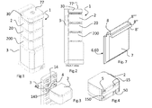
- Figs. 1 and 2 refers to a modular refrigeration apparatus 1 of the above-described type, which comprises one or more modules 2, 20, 200 comprising cells connected to the structure 3, the latter comprising the known functional parts of the refrigerator, i.e. at least the cold air production circuit.
- At least one module 2 can be removed from the structure 3, (all or just some of the modules or cells 2, 20, 200 being removable).
- the module 30 may also be removable, said module being positioned, according to the embodiment shown by way of non-limiting example in Figs. 1 and 2 , on top of the modules 2, 20 and 200 and being characterized by being approximately half shorter than the other modules 2, 20 and 200 and by being accessible by the user through the removal of a cover 77 (which is advantageously transparent) that covers a corresponding aperture obtained in at least a portion of the top surface of the module 30.
- the connector according to the present invention (both in the case that it is suitable for supplying fluid or light) comprises two cooperating parts: a first male part 4,14,40,140 and a second female part 5,15,50,150 that can be coupled together to attach the cell (or module) to the structure.
- This first and second parts ensure the proper mechanical coupling between the cell 2,20,200 and the structure 3, and keep the module 2,20,200 attached to the structure 3, thus playing the role of a mechanical connection between those two, supporting the cell on the structure.
- first male part 4,14,40,140 and the second female part 5,15,50,150 are provided with locking means in order to ensure a stable coupling by countering the relative movements between the male part 4,14,40,140 and the female part 5,15,50,150.
- the locking means may consist of a system comprising a pair of pistons, which in the same time, thanks to matching guides (later on described), will guide the user in the relative movement between the module and the structure.
- a pistons are kept apart by a contrast spring on one part of said connector and slides in the slide guides on the other part of said connector.
- the connector (beside the mechanical coupling function) is provided with means for supplying fluid, or means for supplying light to the module, described later on, so as to perform the function of a fluid connector or of a lighting connector.
- Each module could be provided with one or more fluid connectors and/or with one or more illumination connectors.
- the connector (both of the fluid type as shown in fig. 5, 6 or of the illumination type as shown in fig. 8, 9 ) comprises two cooperating parts: a first male part 4, 14, 40, 140 and a second female part 5, 15, 50, 150, that are meant to be coupled together to support the module 2, 20, 200 to the structure 3; advantageously, the male part 4,14,40,140 of the connector has a parallelepiped convex shape, and the female part 5,15,50,150 has a corresponding concave shape.
- Both the male and the female parts are provided with a curved wall having a wide radius 9 of curvature, so as to help the user to insert the male part in the female part by promoting their relative sliding.
- the male part 4,14 is provided with pistons 11, and the female part 5,15 is provided with corresponding guides 13: during the coupling the pistons 11 slide in the guides 13, until the end of the guide 23 itself, which is provided with holes fitting the pistons 11, thereby stopping the relative motion between the two parts, and assuring the correct coupling, as described later on.
- Figs. 3 and 4 show a preferred embodiment of the connector according to the present invention; in particular, in this embodiment the connector is a fluid connector and consists of a first male part 4 and a second female part 5.
- the female parts 5 and 50 are associated with the module 2 and connect to corresponding male parts 4 and 40 of the fluid connector, thus providing sections for fluid flow from the structure 3 to the cell 2 and vice versa.
- male parts 4, 40 and female parts 5, 50 can be reciprocated between the cell and the structure.
- a single female part 5 may be associated thereto for supplying refrigerating fluid into the cell 30, since the refrigerating fluid is then drained through leaks releasing a metered amount of it into the outside environment, rather than through a refrigerating fluid return path to the structure 3.
- the connector part applied to the structure 3 is connected to suitably thermoinsulated channels arranged inside the structure 3 through outlet/inlet sections located at the same level as the removable modules.
- modules When the modules are removed by the user, said sections can be kept closed through suitable means such as gate valves (on-off damper or stepping type) or through flexible membranes which can be opened by the pressure difference generated by the flow of refrigerated air.
- suitable means such as gate valves (on-off damper or stepping type) or through flexible membranes which can be opened by the pressure difference generated by the flow of refrigerated air.
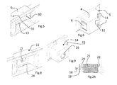
- Figs. 5, 6 and 7 there is shown the first part of a fluid connector and a preferred shape of the shutter 6, 60.
- the shutter 6 is fitted to the male part 4 and co-operates with the shutter 60 fitted to the female part 5 when the male part 4 is inserted into the female part 5, as shown in Figs. 10 to 16 and 17 to 23 described later on.
- the shutter 6, 60 shown in Fig. 7 , is a tiltable shutter and have a general shape of a door, having at least one flat body portion 7, adapted to close the flow section, and an engagement profile 8, preferably located at one edge of said flat portion 7, i.e. in the area of the shutter 6, 60 which is hinged to the fluid connector.
- the shutter 6, 60 is rotatably associated with and closes the body of the fluid connector.
- both shutters 6, 60 takes place through mutual interference between the first and second shutters, in particular through mutual interference between the engagement profiles 8, which are so shaped that the shutters, when set to the interfaced condition, co-operate together to their mutual opening, thus opening the fluid flow section.
- the illustrated engagement profile 8 comprises three different faces 8', 8" and 8''', which are inclined by an increasing angle with respect to the flat portion 7.
- the end face 8''' is perpendicular to the flat portion 7.
- Figs. 13 to 16 show the different steps according to which the shutters 6 and 60, when set to the interfaced condition, mutually contribute to their reciprocal opening by means of the engagement profile 8.
- abutted faces are the surfaces 8'
- abutted faces are the surfaces 8"
- Fig. 16 are the surfaces 8''', the latter being perpendicular to the flat portion 7 and thus allowing the shutter to be fully opened and letting the fluid flow through.
- the engagement profile 8 may be provided either as shown or in other equivalent manners featuring cam profiles, grooved profiles or the like.
- the male part 4 of the fluid connector has a parallelepiped shape wherein one wall is associated with the shutter 6 and the remaining walls are closed, except for one wall, not shown, which is open on a fluid duct of the structure in order to allow the fluid, in particular refrigerated air, to be supplied to the cell.
- the wide radius 9 of the male connector wall opposite to the wall that houses the shutter 6 promotes its relative sliding over the corresponding wall 10 of the female connector part 5 as the connection is made, and facilitates the air flow within the connector itself (male part 4), thus reducing load losses.
- a torsion spring (or a reed spring) mounted to the pin about which the shutter 6, 60 can rotate, and/or a ballast mounted to the shutter near the side opposite to the hinge side, and/or a magnetic shutting system attracting the shutter to the aperture edge.
- Said shutting devices may be advantageously combined with a gasket in order to further improve the sealing effect.
- the remaining portion of the shutter may have a constant thickness and/or contain a seat for insulating material.
- a magnetic system associated with the shutters 6, 60 may be used in order to prevent the male part 4 from detaching from the female part 5 after they have been coupled together.
- magnets having opposite polarities may be applied to the face 8''' so that, when the two shutters 6, 60 interfere with each other, the attraction force between the magnets will force the two shutters to stay in contact with each other, until the user applies a force which overcomes said magnetic attraction.
- the pistons 11 may be replaced in the same position with a pair of rigid, fixed protrusions which, once positioned inside the guides 13, will prevent any side movements between the first part and the second part.
- the female part 5 is so shaped that the surfaces of the female parts 5 adhere to the matching surfaces of the male part 4 as the interfacing is carried out.
- the female part 5 is substantially a parallelepipedon in shape, with surfaces of the same size as the male part 4 (by way of example, said parallelepipedon may be approx. 47mm high, 41mm wide and 70mm deep).
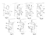
- Figs. 10 to 16 show a cinema-like sequence of sectional views of the interfacing action between the male part 4 and the female part 5.
- FIG. 17 to 23 A corresponding sequence of top views is shown in Figs. 17 to 23 .
- Figs. 8 and 9 show the first part 14 and second part 15 of an illumination connector according to the present invention.
- the first part 14 is the male one and the second part 15 is the female one.
- the first part 14 and second part 15 have two corresponding interfacing sections 16 and 17.
- a light source 18, such as a bulb or LED mounted inside the first part 14 of the illumination connector 14, and an optional lens 19 located in the interfacing section 16.
- the second part 15 of the illumination connector comprises at least one light guide for the light produced by the light source, said light guide being adapted to convey the light produced by the light source into the cell compartment, and comprising a first lens 20, a translucent insulating material 21 (e.g. a silica aerogel, known in the art) and a second lens 22.
- the translucent insulating material 21 may for example be housed in a container, e.g. a tube or a pipe, extending through the insulation of the cell itself so as to transfer the light produced by the source 18, located in the structure 3, into the compartment of the cell 2.
- the translucent insulating material 21 and the lenses 20 and 22 may alternatively be replaced with, for example, optical fibres or the like.
- the first lens 20 is located at the interfacing section 17 so that, when the interfacing sections 16 and 17 are aligned, the light produced by the light source 18 is conveyed into the compartment of the cell 2.
- two female parts 15 and 150 associated with the cell 2 are interfaced to two male parts 14 and 140 of the illumination connector.
- the male parts 14, 140 and female parts 15, 150 can be reciprocated between the cell and the structure. If the cell (e.g. the cell 30) has a low height, it may be associated with just one part (e.g. the female part 15) of the illumination connector.
- the illumination connector is also provided with locking means, e.g. comprising pistons and associated slide guides, just like the fluid connector.
- the locking means with opposing pistons kept apart toward the outer side of the connector are preferably positioned in the housing hole 23 provided in the male part 14 of the illumination connector, and feature similar pistons 11 and spring 12 as the fluid connector shown and described for Fig. 12 .
- the pistons of the illumination connector guide and hold in position the male part 14 and female part 15 of the illumination connector; in particular, as said two parts 14 and 15 are interfaced to each other, they co-operate with matching slide guides 24 provided inside the female part 15.
- the sliding of the pistons 11 protruding from the housing holes 23 in the matching slide guides 24 may stop at two holes engaging the pistons.
- a magnetic system associated with the male part 14 and female part 15 may be provided in order to prevent the male part 14 from detaching from the female part 15 after they have been coupled together.
- magnets having opposite polarities are applied to the end-of-travel flat walls 27,28 of the male part 14 and of the female part 15, which abut against each other when the male part and female part are coupled together, so that the attraction exerted by the magnets will force the male part 14 and female part 15 to stay in contact until the user applies a force which overcomes said magnetic attraction.
- the pistons may be replaced substantially in the same position, i.e. at the housing hole 23, with a pair of rigid, fixed protrusions which, once positioned inside the guides 24, will prevent any side movements between the first part 14 and the second part 15.
- the female part 15 is so shaped that the surfaces of the female parts 15 adhere to the matching surfaces of the male part 14 as the interfacing is carried out.
- the female part 5 is therefore substantially a parallelepipedon in shape, with surfaces of the same size as the male part 4 (by way of example, said parallelepipedon may be approx. 47mm high, 41mm wide and 70mm deep).
- the wide radius 39 promotes its relative sliding over the corresponding wide radius 40 of the female part 15 of the connector as the connection is made.
- the module 2 comprises an aperture to allow access to the inner compartment, and is fitted with sensors, e.g. open-state detection magnetic sensors, adapted to detect when the cell is open and send a corresponding signal to the structure 3, which will then turn on the source 18 in order to illuminate the cell 2.
- the structure 3 may be provided with a sensing device adapted to detect the position of an element (e.g. a magnet) associated with the door of the cell 2 (for example, said door opening by rotating about a vertical axis): in fact, this allows to detect if the door is not properly closed, without having to mount any electrically active component to the cell 2.
- an element e.g. a
- the structure 3 may also be fitted with other sensors, such as cell presence/absence, temperature, humidity, foodstuff preservation state sensors or the like.
- the male-female shape of the fluid connector and illumination connector shown herein should not be understood as limiting, since even a simple flat shape of the first and second parts of the fluid connector and illumination connector may perform the required functions, in this case a proper support for the cell is needed for supporting the cell itself, such for example a supporting plane placed under each cell; the connector in this case assures only the proper coupling between the cells and the structure, but it does not provide mechanical support to the cell itself.
- the male-female shape of the fluid connector and illumination connector advantageously serve as a guide for the correct positioning the cell 2 onto the structure 3, thus assisting the user and guiding the insertion/coupling of the cell 2, 20, 200 onto the structure 3.
- the cell or module may be completely passive, as opposed to the structure which is, on the contrary, active: the structure comprises all the elements which are functionally required for the operations for which the household appliance has been designed, while the cell or module is supplied in its entirety by the structure for performing his operation.
- the above-described fluid and illumination connectors may also be used to much advantage in terms of ease of use in the general field of household appliances, and in particular in any household appliance comprising a cell or a module that can be removed from a structure, and wherein the cell or module needs to be supplied with a flow produced by the structure and/or illuminated by a light source provided on the structure.
- the cell or module may be completely passive, as opposed to an active structure: the structure comprises all the elements which are functionally required for the operations for which the household appliance has been designed, while the cell or module is supplied by the structure.
- the manner in which the fluid and illumination connectors are applied to the structure 3 and to the cell 2 as shown in Figs. 3 and 4 is intended as a particular embodiment provided by way of non-limiting example.
- the connectors are applied to the structure 3 and to the module 2 by mounting a set of horizontal inserts, each comprising a male part of the fluid connector and a male part of the illumination connector, or a female part of the fluid connector and a female part of the illumination connector, and preferably provided with support ribs (e.g. longitudinal or transversal) and elements (e.g.
- baffles adapted to properly convey the flow of refrigerated air, thus reducing load losses.
- Said horizontal inserts may be mounted to the structure 3 by means of matching profiles which interact with one another in order to provide a stable coupling; as an alternative, they may be mounted to the module 2, buried in the insulation material of the module 2 itself.
- the method of application of the fluid and illumination connectors to the structure 3 and to the module 2 shown in Figs. 3 and 4 requires that seats extending horizontally be obtained in the structure 3, in particular in the surface of the structure 3 facing the module 2, for inserting the inserts.
- each of said vertical inserts comprising parts of the fluid connector and illumination connector in order to provide a connection between the structure 3 and the removable modules 2, 20, 200 and 30.
- This first advantageous variant has a lower number of inserts, thus making it easier to mount the inserts themselves to the structure 3.
- the manner in which the fluid and illumination connectors are applied to the structure 3 and to the cell 2 according to the first advantageous variant requires that seats extending vertically be obtained in the structure 3, in particular in the surface of the structure 3 facing the cell 2, for inserting the inserts, the number of said vertically extending seats being preferably two.
- a plurality of inserts are applied to the structure 3 and/or to the module 2, each of which comprises only a single part (i.e. either the male part or the female part) of the fluid connector or illumination connector.
- This second advantageous variant provides ease of maintenance, in that the parts of the fluid connectors or illumination connectors may be replaced separately should they fail.
- the method of application of the fluid and illumination connectors to the structure 3 and to the module 2 according to the first advantageous variant requires that a plurality of small seats be obtained in the structure 3, in particular in the surface of the structure 3 facing the cell 2, for inserting the inserts, said inserts being preferably secured to said seats by means of screws, joints or different removable mechanical connections.
- the parts of the fluid and illumination connectors are applied to the structure 3 and/or to the module 2 directly when moulding the structure 3 and the module 2, said parts being thus obtained in one piece with the structure 3 or module 2.
- This third advantageous variant is particularly beneficial in terms of cost, simplicity and accuracy of application of the fluid and illumination connectors to the structure 3 and to the module 2, while however reducing the ease of maintenance of the connector parts.
- the material used for manufacturing the parts of the fluid and illumination connectors it may be any material, provided that it has good workability and mechanical strength properties (especially when the parts are applied to the structure according to said third advantageous variant): therefore, said material may be conveniently chosen among steel, aluminium, polymeric materials or the like.
- the modular refrigeration apparatus may have an additional feature: the module 90 can be a trolley-like module, provided with wheels 92 and a retractable handle bar 93.
- a handle bar 93 could be tiltable, with respect to a horizontal axis passing through a hinge connecting the handle 93 to the module 90; moreover the handle could be made as a belt connected to the module 90.
- the structure 3 is provided with all the necessary means for producing cold air that is supplied to the trolley-like module 90, and for providing illumination for it.
- the trolley-like module 90 can be joined to the structure by means of the connector before described: in this case the module is not properly “supported” by means of said connectors, but it is anyway kept in place when attached to the structure.
- trolley-like module 90 An advantageous feature of the trolley-like module 90 is that in this case those connectors could be of the simple flat shape without any needs for a supporting plane (for the trolley-like module stands on his wheels on the floor).
- the trolley-like module 90 as module 2,20,200 may be completely passive, as opposed to the structure 3 which is, on the contrary, active: the structure 3 comprises all the elements which are functionally required for the operations for which the household appliance has been designed, while the trolley-like module 90 is supplied in its entirety by the structure for performing his operation, with cold air and lighting.
- the retractable handle bar 93 can be extracted from the closed position depicted in fig. 26 , when the module 90 is detached from the structure 3, and used for controlling the module 90 in his movement over the wheels.
- the module 90 is therefore movable around so as to reach virtually any location without straining the user.
- the trolley-like module 90 can be simply a tank for liquid materials, such as water or wine, or beer. To this extent the module 90 is provided with a cap 91, through which it could be filled or emptied.
- trolley-like module 90 can be supplied by the structure with cold air or light even without using the above described connectors.
- concept of realizing a trolley-like module has to be construed as an innovative concept per se.
Landscapes
- Engineering & Computer Science (AREA)
- Chemical & Material Sciences (AREA)
- Combustion & Propulsion (AREA)
- Mechanical Engineering (AREA)
- General Engineering & Computer Science (AREA)
- Physics & Mathematics (AREA)
- Thermal Sciences (AREA)
- Devices That Are Associated With Refrigeration Equipment (AREA)
- Filters For Electric Vacuum Cleaners (AREA)
- Apparatus Associated With Microorganisms And Enzymes (AREA)
- Arrangement Of Elements, Cooling, Sealing, Or The Like Of Lighting Devices (AREA)
Abstract
The cell supply may be a fluid supply and/or a lighting of the cell compartment (2,20,200).
Description
- The present invention relates to a device for supplying cells, in particular removable ones, of household appliances.
- Herein the phrase "cells of household appliances" refers to those parts of household appliances which are provided with a compartment adapted to contain the materials treated by the appliance.
- For example, the cell of an oven comprises the oven cavity in which food is placed for cooking, while the cell of a refrigerator or freezer comprises the refrigerated compartment adapted to store foodstuffs to be cooled/preserved.
- The cell is associated with a structure of the household appliance, i.e. a functional unit, which comprises all those parts which are functionally required for the operation of the household appliance. For example, the functional unit or structure of a refrigerator comprises at least the cold air generating circuit, whereas in an oven it comprises at least the hot air generating heaters.
- The present invention applies to household appliances wherein the cells can be removed from the structure, i.e. wherein the cells can be attached and detached to the structure.
- Cells of household appliances are normally supplied with fluids required for the operation of the appliance and are illuminated.
- For example, the refrigerated cell of a refrigerator is supplied with a cold fluid, typically cold air, and is fitted with a lighting system.
- If the cell is a removable one, it is necessary to provide suitable mechanical connections between the cell and the structure in order to make it easy to support the cell to the structure, while at the same time it is necessary to supply the cell with fluid and with electrical current for lighting.
- For this purpose the prior art solution is to provide different connections for each function to be performed: a mechanical connection for joining the cell to the structure, a fluid connection (normally a simple pipe starting from the structure and leading to the cell) and an electrical connection (that supplies a lamp provided in the cell for lighting the cell itself).
- When attaching each cell the user must therefore assure that each connection (mechanical, fluid and electrical) is connected, for ensuring proper functioning of the cell; this is time consuming and not fault-proof, because the user can forget to ensure that one or more of those connections are properly connected; for instance forgetting the fluid connection would lead to have a cell not refrigerated, thereby wasting the contained goods to be preserved.
- It is the object of the present invention to provide a device for supplying cells of household appliances which can overcome the inherent drawbacks of prior-art methods and devices.
- The device adapted to attain said object incorporates the features set out in the appended claims, which are intended as an integral part of the present description.
- The present invention is based on the general idea of supplying the cell only when the cell is joined mechanically to the structure and particularly only when it is properly positioned relative to the structure. The cell supply may be a fluid supply and/or a lighting of the cell compartment.
- A first embodiment of the device according to the present invention provides a mechanical connection together with a fluid connection, in such a way that when the mechanical connection between the cell and the structure is established in a proper way, then it is assured in the same time the fluid supply to the cell.
- According to a second embodiment, the device consists of a connector for illuminating the cell of the household appliance, when the latter is mechanically connected to the structure.
- This result is achieved by employing a fluid supply connector, or fluid connector, for delivering fluid to/from the cell, wherein said fluid connector is divided into two distinct parts, i.e. a first part associated with the structure and a second part associated with the cell, and the first part and second part are operationally associated with the fluid circuit of the structure and with the cell fluid ducts. In particular, the first and second parts of the fluid connector co-operate mechanically with each other: both the first and second parts, in fact, have an associated shutter which opens or closes the fluid flow section, said two shutter being opened or closed due to mutual interference between said first and second shutter. The shutters have a mutual engagement profile which is so designed that, when the shutters are in the interfacing condition, they co-operate mutually to their opening, thus opening the fluid flow section as well.
- The above-mentioned connector may be advantageously used for both supplying and draining the fluid to/from the cell.
- Since a structure and a cell are used which are fitted with either the first or the second part of the device according to the present invention, the fluid connector according to the present invention offers several advantages because the cell can be positioned and supplied very easily: in fact, in order to supply the cell with fluid it is sufficient to set the shutters of the first and second parts of the fluid connector to the interfaced condition.
- An advantage of particular relevance is a combination of a connector according to the present invention and a modular apparatus, e.g. a modular refrigeration apparatus.
- Generally, a modular refrigeration apparatus can be defined as an apparatus adapted to preserve foodstuffs. Such an apparatus comprises: one or more cells associated to corresponding modules, each of them being adapted to keep foodstuffs in a certain preservation state, those modules being attachable/detachable to a structure comprising the functional unit adapted to generate a refrigerating fluid (normally a cold air stream); the structure further comprises distribution devices adapted to distribute the refrigerating fluid generated by the functional unit or structure, wherein the modules comprise connection means providing a connection to said distribution means, said connection means being adapted to allow refrigerated air to be supplied into said one or more cells, preferably into at least one inner compartment thereof, and to ensure that said one or more modules can be disconnected from said distribution means so as to allow a user to remove said one or more modules.
- In other words, a modular refrigerator essentially comprises a number of removable modules, each comprising a cell, associated with a structure which is common to all modules and which is responsible for generating at least-the refrigerating fluid.
- By combining a modular refrigeration apparatus with a connector according to the present invention, it is possible to enhance the advantages offered by a modular refrigeration apparatus: removing or mounting the modules from/to the structure is in fact much easier because the user does not have to manually connect the refrigerating fluid ducts and then open a valve or the like in order to turn on the cell supply, or provide an electrical connection between the structure and the modules; on the contrary, the fluid flow sections are opened automatically, and/or the cell is illuminated as the user joins mechanically the module to the structure, by positioning it correctly relative to the structure.
- The shutters of the first and second parts of the connector, once they have been interfaced to each other, will automatically open the fluid flow section, thus supplying fluid to the cell or allowing fluid to be drained from the cell: the fluid connector according to the present invention may in fact be used both for opening/closing the flow sections of the refrigerating fluid delivery ducts running from the structure to the cell and for opening/closing the flow sections of the refrigerating fluid return ducts running from the cell to the structure.
- According to a second embodiment, the device consists of a connector for illuminating the cell of the household appliance.
- In known refrigerators and ovens, for example, cells are typically provided with electrically active components such as a power circuit for an illumination bulb or LED arranged inside the cell.
- The second embodiment of the present invention provides a cell illumination connector consisting of a first connector part associated with the structure and a second connector part associated with the cell.
- The first part of the illumination connector comprises at least one light source, e.g. a bulb or LED, while the second part of the connector comprises a light guide for the light generated by the light source, said light guide being adapted to convey the light generated by the light source into the cell compartment.
- This solution overcomes the drawback of the prior art, which requires an electric circuit and/or a control circuit in order to provide the cell lighting function: as a matter of fact, by simply interfacing the first part to the second part of the illumination connector it is possible to illuminate the inner cell compartment without needing a cell-specific illumination circuit, since the cell comprises a light guide, which is an electrically passive component, and the bulb or LED and the associated circuit are incorporated into the structure.
- The elimination of the control circuit and of the active lighting means used as a light source inside the cell allows a removable cell to be coupled to a structure in a much simpler manner.
- In this second embodiment as well, by combining a modular refrigeration apparatus with an illumination connector according to the present invention it is possible to further enhance the advantages offered by a modular refrigeration apparatus: removing or mounting the cells or containers from/to the structure is in fact much easier, because the user does not have to make electric connections in order to illuminate the cell; on the contrary, he/she only needs to interface the cell to the structure correctly, i.e. to connect together the first and second parts of an illumination connector according to the present invention.
- The combination consisting of a fluid connector and an illumination connector provided both on the same module provides a simple and economical way of mounting a cell to a structure, ensuring in the same time mechanical connection between those two, as well as fluid supply and lighting supply.
- The combination of said connector turns out to be even more advantageous in a modular refrigeration apparatus as described, since in this case the user can simply and quickly remove or mount the module from/to the structure and automatically the fluid and lighting supply is guaranteed.
- A further advantage that is to be noted is that this connection is fault-proof: when the user joins mechanically the removable cell to the structure, at the same time this provides refrigerated fluid and lighting to the cell, thereby avoiding that the user could forget to connect the fluid or light supply.
- Although the annexed drawings and the descriptions thereof refer by way of example to a modular refrigeration apparatus, the present invention is also applicable to any other household appliance provided with at least one cell and one structure without departing from the teachings and protection scope of the present invention.
- The device according to the present invention will become apparent, together with its further advantages, from the following detailed description and from the annexed drawings, which are supplied by way of non-limiting example, wherein:
-
Figs. 1 and 2 are two views of a modular refrigeration apparatus; -
Fig. 3 is a perspective view of a cell and a structure of the apparatus ofFigs. 1 and 2 ; -
Fig. 4 is a perspective view of the cell ofFig.3 ; -
Figs. 5 and 6 are two perspective views of the first and second parts of the fluid connector according to a preferred embodiment; -
Fig. 7 is a perspective view of a door of the fluid connector; -
Figs. 8 and 9 are two perspective views of the first and second parts of the illumination connector according to a preferred embodiment; -
Figs. 10 to 16 are sectional views of a mounting sequence relating to the fluid connector ofFigs. 5 and 6 ; -
Fig. 17 to 23 are top views of the same mounting sequence ofFigs. 10 to 16 ; -
Fig. 24 shows some components of the illumination connector ofFigs. 8 and 9 . - The example shown in
Figs. 1 and 2 refers to amodular refrigeration apparatus 1 of the above-described type, which comprises one ormore modules structure 3, the latter comprising the known functional parts of the refrigerator, i.e. at least the cold air production circuit. - As shown in
Figs. 3 and 4 , at least onemodule 2 can be removed from thestructure 3, (all or just some of the modules orcells - In addition, the
module 30 may also be removable, said module being positioned, according to the embodiment shown by way of non-limiting example inFigs. 1 and 2 , on top of themodules other modules module 30. - As can be seen in the attached drawings, the connector according to the present invention (both in the case that it is suitable for supplying fluid or light) comprises two cooperating parts: a first
male part female part - This first and second parts ensure the proper mechanical coupling between the
cell 2,20,200 and thestructure 3, and keep themodule 2,20,200 attached to thestructure 3, thus playing the role of a mechanical connection between those two, supporting the cell on the structure. - As can be seen later, the first
male part female part male part female part - The locking means may consist of a system comprising a pair of pistons, which in the same time, thanks to matching guides (later on described), will guide the user in the relative movement between the module and the structure. Such a pistons are kept apart by a contrast spring on one part of said connector and slides in the slide guides on the other part of said connector.
- According to the present invention, the connector (beside the mechanical coupling function) is provided with means for supplying fluid, or means for supplying light to the module, described later on, so as to perform the function of a fluid connector or of a lighting connector.
- Each module could be provided with one or more fluid connectors and/or with one or more illumination connectors.
- Generally speaking, with reference to attached
drawings fig. 5, 6 or of the illumination type as shown infig. 8, 9 ) comprises two cooperating parts: a firstmale part female part module structure 3; advantageously, themale part female part - It is preferable to apply the
female parts cell 2, since they have no projecting portions, being concave, and are therefore less bulky and subject to damage. - Both the male and the female parts are provided with a curved wall having a
wide radius 9 of curvature, so as to help the user to insert the male part in the female part by promoting their relative sliding. - In order to guide the user in the coupling operation the
male part pistons 11, and thefemale part pistons 11 slide in theguides 13, until the end of theguide 23 itself, which is provided with holes fitting thepistons 11, thereby stopping the relative motion between the two parts, and assuring the correct coupling, as described later on. -
Figs. 3 and 4 show a preferred embodiment of the connector according to the present invention; in particular, in this embodiment the connector is a fluid connector and consists of a firstmale part 4 and a secondfemale part 5. - The
female parts module 2 and connect to correspondingmale parts structure 3 to thecell 2 and vice versa. - Obviously the
male parts female parts - If the cell (e.g. cell 30) has a low height, a single
female part 5 may be associated thereto for supplying refrigerating fluid into thecell 30, since the refrigerating fluid is then drained through leaks releasing a metered amount of it into the outside environment, rather than through a refrigerating fluid return path to thestructure 3. - The connector part applied to the
structure 3 is connected to suitably thermoinsulated channels arranged inside thestructure 3 through outlet/inlet sections located at the same level as the removable modules. - When the modules are removed by the user, said sections can be kept closed through suitable means such as gate valves (on-off damper or stepping type) or through flexible membranes which can be opened by the pressure difference generated by the flow of refrigerated air.
- Referring now to
Figs. 5, 6 and7 , there is shown the first part of a fluid connector and a preferred shape of theshutter - The
shutter 6 is fitted to themale part 4 and co-operates with theshutter 60 fitted to thefemale part 5 when themale part 4 is inserted into thefemale part 5, as shown inFigs. 10 to 16 and17 to 23 described later on. - The
shutter Fig. 7 , is a tiltable shutter and have a general shape of a door, having at least oneflat body portion 7, adapted to close the flow section, and anengagement profile 8, preferably located at one edge of saidflat portion 7, i.e. in the area of theshutter shutter - The opening and closing of both
shutters engagement profiles 8, which are so shaped that the shutters, when set to the interfaced condition, co-operate together to their mutual opening, thus opening the fluid flow section. - The illustrated
engagement profile 8 comprises threedifferent faces 8', 8" and 8''', which are inclined by an increasing angle with respect to theflat portion 7. In particular, the end face 8''' is perpendicular to theflat portion 7. -
Figs. 13 to 16 show the different steps according to which theshutters engagement profile 8. - In
Fig. 14 the abutted faces are the surfaces 8', whereas inFig. 15 the abutted faces are thesurfaces 8" and inFig. 16 are the surfaces 8''', the latter being perpendicular to theflat portion 7 and thus allowing the shutter to be fully opened and letting the fluid flow through. - The
engagement profile 8 may be provided either as shown or in other equivalent manners featuring cam profiles, grooved profiles or the like. - Advantageously, the
male part 4 of the fluid connector has a parallelepiped shape wherein one wall is associated with theshutter 6 and the remaining walls are closed, except for one wall, not shown, which is open on a fluid duct of the structure in order to allow the fluid, in particular refrigerated air, to be supplied to the cell. - The
wide radius 9 of the male connector wall opposite to the wall that houses theshutter 6 promotes its relative sliding over the correspondingwall 10 of thefemale connector part 5 as the connection is made, and facilitates the air flow within the connector itself (male part 4), thus reducing load losses. - In order to ensure a hermetic seal when the
shutter shutter - Said shutting devices may be advantageously combined with a gasket in order to further improve the sealing effect.
- In particular, the remaining portion of the shutter may have a constant thickness and/or contain a seat for insulating material.
- In order to avoid detachments of the male and the female parts alternatively, a magnetic system associated with the
shutters male part 4 from detaching from thefemale part 5 after they have been coupled together. For example, magnets having opposite polarities may be applied to the face 8''' so that, when the twoshutters pistons 11 may be replaced in the same position with a pair of rigid, fixed protrusions which, once positioned inside theguides 13, will prevent any side movements between the first part and the second part. - The
female part 5 is so shaped that the surfaces of thefemale parts 5 adhere to the matching surfaces of themale part 4 as the interfacing is carried out. - Therefore, the
female part 5 is substantially a parallelepipedon in shape, with surfaces of the same size as the male part 4 (by way of example, said parallelepipedon may be approx. 47mm high, 41mm wide and 70mm deep). -
Figs. 10 to 16 show a cinema-like sequence of sectional views of the interfacing action between themale part 4 and thefemale part 5. - A corresponding sequence of top views is shown in
Figs. 17 to 23 . - In
Figs. 10 to 13 , and in the correspondingFigs. 17 to 20 , the twoshutters male part 4 and thefemale part 5 is guided by the sliding action of thepistons 11 in theguides 13, as clearly shown inFigs. 11 to 13 and in the correspondingFigs. 18 to 20 , thus advantageously ensuring an optimal interfacing action. - In
Figs. 14 to 16 and in the correspondingFigs. 21 to 23 , the fluid flow section is opened gradually as theshutters Figs. 16 and23 is attained. -
Figs. 8 and 9 show thefirst part 14 andsecond part 15 of an illumination connector according to the present invention. In this preferred embodiment, thefirst part 14 is the male one and thesecond part 15 is the female one. Thefirst part 14 andsecond part 15 have twocorresponding interfacing sections - Along with
Fig. 24 , these drawings illustrate the functional components of the first and second parts of the illumination connector in an exemplifying and simplified form: alight source 18, such as a bulb or LED, mounted inside thefirst part 14 of theillumination connector 14, and anoptional lens 19 located in theinterfacing section 16. Thesecond part 15 of the illumination connector comprises at least one light guide for the light produced by the light source, said light guide being adapted to convey the light produced by the light source into the cell compartment, and comprising afirst lens 20, a translucent insulating material 21 (e.g. a silica aerogel, known in the art) and asecond lens 22. The translucent insulatingmaterial 21 may for example be housed in a container, e.g. a tube or a pipe, extending through the insulation of the cell itself so as to transfer the light produced by thesource 18, located in thestructure 3, into the compartment of thecell 2. - The translucent insulating
material 21 and thelenses first lens 20 is located at theinterfacing section 17 so that, when the interfacingsections light source 18 is conveyed into the compartment of thecell 2. - With reference to
Figs. 3 and 4 , twofemale parts 15 and 150 associated with thecell 2 are interfaced to twomale parts male parts female parts 15, 150 can be reciprocated between the cell and the structure. If the cell (e.g. the cell 30) has a low height, it may be associated with just one part (e.g. the female part 15) of the illumination connector. - The illumination connector is also provided with locking means, e.g. comprising pistons and associated slide guides, just like the fluid connector.
- In particular, the locking means with opposing pistons kept apart toward the outer side of the connector are preferably positioned in the
housing hole 23 provided in themale part 14 of the illumination connector, and featuresimilar pistons 11 andspring 12 as the fluid connector shown and described forFig. 12 . - The pistons of the illumination connector guide and hold in position the
male part 14 andfemale part 15 of the illumination connector; in particular, as said twoparts female part 15. - The sliding of the
pistons 11 protruding from thehousing holes 23 in the matching slide guides 24 may stop at two holes engaging the pistons. - As an alternative, a magnetic system associated with the
male part 14 andfemale part 15 may be provided in order to prevent themale part 14 from detaching from thefemale part 15 after they have been coupled together. For example, magnets having opposite polarities are applied to the end-of-travel flat walls 27,28 of themale part 14 and of thefemale part 15, which abut against each other when the male part and female part are coupled together, so that the attraction exerted by the magnets will force themale part 14 andfemale part 15 to stay in contact until the user applies a force which overcomes said magnetic attraction. In this case, the pistons may be replaced substantially in the same position, i.e. at thehousing hole 23, with a pair of rigid, fixed protrusions which, once positioned inside theguides 24, will prevent any side movements between thefirst part 14 and thesecond part 15. - The
female part 15 is so shaped that the surfaces of thefemale parts 15 adhere to the matching surfaces of themale part 14 as the interfacing is carried out. - The
female part 5 is therefore substantially a parallelepipedon in shape, with surfaces of the same size as the male part 4 (by way of example, said parallelepipedon may be approx. 47mm high, 41mm wide and 70mm deep). The wide radius 39 promotes its relative sliding over the correspondingwide radius 40 of thefemale part 15 of the connector as the connection is made. Themodule 2 comprises an aperture to allow access to the inner compartment, and is fitted with sensors, e.g. open-state detection magnetic sensors, adapted to detect when the cell is open and send a corresponding signal to thestructure 3, which will then turn on thesource 18 in order to illuminate thecell 2. Particularly advantageously, thestructure 3 may be provided with a sensing device adapted to detect the position of an element (e.g. a magnet) associated with the door of the cell 2 (for example, said door opening by rotating about a vertical axis): in fact, this allows to detect if the door is not properly closed, without having to mount any electrically active component to thecell 2. - The
structure 3 may also be fitted with other sensors, such as cell presence/absence, temperature, humidity, foodstuff preservation state sensors or the like. - The male-female shape of the fluid connector and illumination connector shown herein should not be understood as limiting, since even a simple flat shape of the first and second parts of the fluid connector and illumination connector may perform the required functions, in this case a proper support for the cell is needed for supporting the cell itself, such for example a supporting plane placed under each cell; the connector in this case assures only the proper coupling between the cells and the structure, but it does not provide mechanical support to the cell itself.
- The male-female shape of the fluid connector and illumination connector advantageously serve as a guide for the correct positioning the
cell 2 onto thestructure 3, thus assisting the user and guiding the insertion/coupling of thecell structure 3. - When combining one or more fluid connectors and one or more illumination connectors with a modular refrigeration apparatus as described above, said apparatus becomes very easy to use because the modules can be positioned correctly, mechanically supported and held in position, as well as supplied with fluid and light or illumination in a particularly advantageous simplified manner through the fluid and illumination connectors according to the present invention.
- Further to this the cell or module may be completely passive, as opposed to the structure which is, on the contrary, active: the structure comprises all the elements which are functionally required for the operations for which the household appliance has been designed, while the cell or module is supplied in its entirety by the structure for performing his operation.
- Nevertheless, the above-described fluid and illumination connectors may also be used to much advantage in terms of ease of use in the general field of household appliances, and in particular in any household appliance comprising a cell or a module that can be removed from a structure, and wherein the cell or module needs to be supplied with a flow produced by the structure and/or illuminated by a light source provided on the structure. Advantageously, in fact, the cell or module may be completely passive, as opposed to an active structure: the structure comprises all the elements which are functionally required for the operations for which the household appliance has been designed, while the cell or module is supplied by the structure.
- As far as the possible variants of the present invention are concerned, it should be underlined that the manner in which the fluid and illumination connectors are applied to the
structure 3 and to thecell 2 as shown inFigs. 3 and 4 is intended as a particular embodiment provided by way of non-limiting example. InFigs. 3 and 4 , the connectors are applied to thestructure 3 and to themodule 2 by mounting a set of horizontal inserts, each comprising a male part of the fluid connector and a male part of the illumination connector, or a female part of the fluid connector and a female part of the illumination connector, and preferably provided with support ribs (e.g. longitudinal or transversal) and elements (e.g. baffles) adapted to properly convey the flow of refrigerated air, thus reducing load losses. Said horizontal inserts may be mounted to thestructure 3 by means of matching profiles which interact with one another in order to provide a stable coupling; as an alternative, they may be mounted to themodule 2, buried in the insulation material of themodule 2 itself. The method of application of the fluid and illumination connectors to thestructure 3 and to themodule 2 shown inFigs. 3 and 4 requires that seats extending horizontally be obtained in thestructure 3, in particular in the surface of thestructure 3 facing themodule 2, for inserting the inserts. - According to a first advantageous variant of the above-described method of application of the fluid and illumination connectors, two vertical inserts, instead of horizontal ones, are applied to the
structure 3, each of said vertical inserts comprising parts of the fluid connector and illumination connector in order to provide a connection between thestructure 3 and theremovable modules structure 3. The manner in which the fluid and illumination connectors are applied to thestructure 3 and to thecell 2 according to the first advantageous variant requires that seats extending vertically be obtained in thestructure 3, in particular in the surface of thestructure 3 facing thecell 2, for inserting the inserts, the number of said vertically extending seats being preferably two. - According to a second advantageous variant of the method of application of the fluid and illumination connectors, a plurality of inserts are applied to the
structure 3 and/or to themodule 2, each of which comprises only a single part (i.e. either the male part or the female part) of the fluid connector or illumination connector. This second advantageous variant provides ease of maintenance, in that the parts of the fluid connectors or illumination connectors may be replaced separately should they fail. The method of application of the fluid and illumination connectors to thestructure 3 and to themodule 2 according to the first advantageous variant requires that a plurality of small seats be obtained in thestructure 3, in particular in the surface of thestructure 3 facing thecell 2, for inserting the inserts, said inserts being preferably secured to said seats by means of screws, joints or different removable mechanical connections. - According to a third advantageous variant of the method of application of the fluid and illumination connectors, the parts of the fluid and illumination connectors are applied to the
structure 3 and/or to themodule 2 directly when moulding thestructure 3 and themodule 2, said parts being thus obtained in one piece with thestructure 3 ormodule 2. This third advantageous variant is particularly beneficial in terms of cost, simplicity and accuracy of application of the fluid and illumination connectors to thestructure 3 and to themodule 2, while however reducing the ease of maintenance of the connector parts. - Finally, as regards the material used for manufacturing the parts of the fluid and illumination connectors, it may be any material, provided that it has good workability and mechanical strength properties (especially when the parts are applied to the structure according to said third advantageous variant): therefore, said material may be conveniently chosen among steel, aluminium, polymeric materials or the like.
- According to
fig. 25 and 26 the modular refrigeration apparatus may have an additional feature: themodule 90 can be a trolley-like module, provided withwheels 92 and aretractable handle bar 93. However, such ahandle bar 93 could be tiltable, with respect to a horizontal axis passing through a hinge connecting thehandle 93 to themodule 90; moreover the handle could be made as a belt connected to themodule 90. - As before disclosed the
structure 3 is provided with all the necessary means for producing cold air that is supplied to the trolley-like module 90, and for providing illumination for it. For example the trolley-like module 90 can be joined to the structure by means of the connector before described: in this case the module is not properly "supported" by means of said connectors, but it is anyway kept in place when attached to the structure. - An advantageous feature of the trolley-
like module 90 is that in this case those connectors could be of the simple flat shape without any needs for a supporting plane (for the trolley-like module stands on his wheels on the floor). - The trolley-
like module 90 asmodule 2,20,200 may be completely passive, as opposed to thestructure 3 which is, on the contrary, active: thestructure 3 comprises all the elements which are functionally required for the operations for which the household appliance has been designed, while the trolley-like module 90 is supplied in its entirety by the structure for performing his operation, with cold air and lighting. - The
retractable handle bar 93 can be extracted from the closed position depicted infig. 26 , when themodule 90 is detached from thestructure 3, and used for controlling themodule 90 in his movement over the wheels. - The
module 90 is therefore movable around so as to reach virtually any location without straining the user. - An additional feature is that the trolley-
like module 90 can be simply a tank for liquid materials, such as water or wine, or beer. To this extent themodule 90 is provided with acap 91, through which it could be filled or emptied. - It has to be understood that the trolley-
like module 90 can be supplied by the structure with cold air or light even without using the above described connectors. Thus, the concept of realizing a trolley-like module has to be construed as an innovative concept per se.
Claims (21)
- Connector for supporting a cell or module (2,20,200) to a structure (3) of a household appliance, said cell or module (2,20,200) being provided with a compartment adapted to contain the materials treated by the appliance, and said structure (3) being provided with functional units for performing the operation of such an appliance, characterized in that said connector comprise means for supply the cell or module (2,20,200).
- Connector according to claim 1, characterized in that it comprises two cooperating part, a first part (4,14,40,140) provided on said cell or module (2,20,200) and a second part (5,15,50,150) provided on said structure (3), so as to perform a mechanical coupling between the cell or module and the structure (3).
- Connector according to claim 2, characterized in that it is provided with locking means in order to ensure a stable coupling by countering the relative movements between the first part (4,14,40,140) and the second part (5,15,50,150).
- Connector according to claim 2 or 3, characterized in that the first part is a male part (4,14,40,140) having a convex shape, and the second part is a female part (5,15,50,150) having a corresponding concave shape, particularly such a shape is a parallelepiped shape.
- Connector according to one or more of the preceding claims, characterized in that said connector is a fluid connector adapted to supply/drain a fluid to/from the cell (2,20,200), wherein the first part and the second part are operationally associated with the fluid circuit of the structure and with the fluid ducts of the cell, respectively, said first part and said second part of the fluid connector being mutually co-operating with each other mechanically.
- Connector according to the preceding claim, characterized in that said first part and said second part of said fluid connector comprise a corresponding shutter (6,60) which opens or closes a fluid flow section, the opening and closing of said two shutters (6,60) taking place through mutual interference between the first shutter (6) and second shutter (60) by means of a reciprocal engagement profile (8) so that, when said two shutters (6,60) are set to the interfaced condition, they mutually co-operate to their reciprocal opening.
- Connector according to the preceding claim, characterized in that said shutters (6,60) are rotatably hinged to said first part and said second part, said doors (6,60) being fitted with at least one flat body portion (7) adapted to close the flow section and with an engagement profile (8) preferably located at one edge of said flat portion (7), said engagement profile (8) comprising one or more faces (8', 8", 8'''), which are inclined by an increasing angle with respect to said flat portion (7), and that at least one of said faces (8''') being the end face of said engagement profile (8) is perpendicular to said flat portion (7).
- Connector according to any of the preceding claims, characterized in that said shutter (6,60) is fitted with a shutting device, such as a torsion spring or a reed spring, mounted to the pin about which the shutter (6, 60) rotate, and/or a ballast mounted to the shutter near the side opposite to the hinge side, and/or a magnetic shutting system attracting the shutter to the aperture edge.
- Connector according to claim 1 to 4, characterized in that said connector is an illumination connector and wherein said first part comprises at least one light source, e.g. a bulb or LED, whereas said second part comprises a light guide for the light produced by said light source, said light guide being adapted to convey the light produced by the light source into the cell compartment when said first part and second part are properly interfaced to each other.
- Connector according to the preceding claim, characterized in that said light guide comprises a first lens (20), a translucent insulating material (21) and a second lens (22), said translucent insulating material (21) being housed in a container extending through the insulation of the cell (2), and said first lens being located at said interfacing section (17).
- Connector according to claim 15, characterized in that said light guide is comprises a silica aerogel.
- Connector according to one or more of the preceding claims, characterized in that at least one side wall of said male part and said female part is a curved wall having a wide radius (39,40) adapted to facilitate the connection between said male part (14,140) and said female part (15,150).
- Household appliance comprising at least one cell or module (2,20,200) and at least one structure (3), wherein said structure comprises a functional unit including those parts which are functionally required for the operation of the household appliance, and said cell (2,20,200) is operationally associated in a removable fashion with said structure (3), characterized in that it comprises at least one connector for supporting said cell or module (2,20, 200) to the structure of the household appliance, according to any of the preceding claims.
- Household appliance according to the preceding claim, characterized by being a modular refrigeration apparatus comprising at least one structure (3) and at least one removable module, said module being supplied with refrigerating fluid and/or illuminated through at least one connector according to any of claims 1 to 12.
- Household appliance according to the preceding claim, characterized in that each cell (2,20,200) comprises at least one female part (5), in particular two female parts (5,50), of a connector according to any of claims 1 to 12, and that the structure comprises one or more matching male parts (4,40) of a connector according to any of claims 1 to 12, each male-female pair (4,5 and 40,50) being used for fluid supply and/or drainage of cold air between said cell and said structure or for illuminating the internal chamber of said module.
- Household appliance comprising at least one cell or module (2,20,200,90) and at least one structure (3), wherein said structure comprises a functional unit including those parts which are functionally required for the operation of the household appliance, and said module (2,20,200,90) is operationally associated in a removable fashion with said structure (3), characterized in that at least a module is a trolley-like module (90), provided with wheels (92).
- Household appliance according to claim 16, wherein said trolley-like module (90) comprises a retractable handle bar (93).
- Household appliance according to claim 16 or 17 in which the structure (3) comprises all the elements which are functionally required for the operations for which the household appliance has been designed, while the trolley-like module (90) is supplied by the structure with cold air and/or lighting.
- Household appliance according to claim 18 in which the trolley-like module (90) is a tank for liquid materials, provided with a cap (91), through which it could be filled or emptied.
- Household appliance according to claim 18 in which the trolley-like module and the structure are connected by means of connector according to one or more of claims 1 to 12.
- Module (90) for a household appliance according to any of claims from 16 to 20, characterized in that it is a trolley-like module (90), provided with wheels (92) and a retractable handle (93).
Priority Applications (1)
| Application Number | Priority Date | Filing Date | Title |
|---|---|---|---|
| PL08154612T PL2018820T3 (en) | 2007-07-23 | 2008-04-16 | Household appliance |
Applications Claiming Priority (1)
| Application Number | Priority Date | Filing Date | Title |
|---|---|---|---|
| IT000541A ITTO20070541A1 (en) | 2007-07-23 | 2007-07-23 | DEVICE FOR FEEDING CELLS OF HOUSEHOLD APPLIANCES, IN PARTICULAR FOR DETACHABLE CELLS |
Publications (2)
| Publication Number | Publication Date |
|---|---|
| EP2018820A1 true EP2018820A1 (en) | 2009-01-28 |
| EP2018820B1 EP2018820B1 (en) | 2011-01-05 |
Family
ID=39711339
Family Applications (1)
| Application Number | Title | Priority Date | Filing Date |
|---|---|---|---|
| EP08154612A Not-in-force EP2018820B1 (en) | 2007-07-23 | 2008-04-16 | Household appliance |
Country Status (5)
| Country | Link |
|---|---|
| EP (1) | EP2018820B1 (en) |
| AT (1) | ATE493912T1 (en) |
| DE (1) | DE602008004282D1 (en) |
| IT (1) | ITTO20070541A1 (en) |
| PL (1) | PL2018820T3 (en) |
Cited By (2)
| Publication number | Priority date | Publication date | Assignee | Title |
|---|---|---|---|---|
| WO2014095855A1 (en) * | 2012-12-19 | 2014-06-26 | BSH Bosch und Siemens Hausgeräte GmbH | Refrigeration device having an air channel |
| JP2019132504A (en) * | 2018-01-31 | 2019-08-08 | 日立グローバルライフソリューションズ株式会社 | refrigerator |
Families Citing this family (1)
| Publication number | Priority date | Publication date | Assignee | Title |
|---|---|---|---|---|
| ITPR20130094A1 (en) * | 2013-11-21 | 2015-05-22 | Indesit Co Spa | FREE INSTALLATION KITCHEN. |
Citations (4)
| Publication number | Priority date | Publication date | Assignee | Title |
|---|---|---|---|---|
| US3440834A (en) * | 1967-01-11 | 1969-04-29 | Mitsui O S K Lines Ltd | Apparatus for transporting refrigerating containers and cooled containers used therefor |
| FR2292942A1 (en) * | 1974-11-29 | 1976-06-25 | Gruenzweig Hartmann Glasfaser | AIR COOLING DEVICE FOR COOLING CONTAINERS |
| WO1994013184A1 (en) | 1992-12-09 | 1994-06-23 | Beltec International | Cabinet-style apparatus for transferring heat to food and cooling food |
| GB2372309A (en) * | 2001-02-14 | 2002-08-21 | Works Design Ltd | Goods storage apparatus |
-
2007
- 2007-07-23 IT IT000541A patent/ITTO20070541A1/en unknown
-
2008
- 2008-04-16 PL PL08154612T patent/PL2018820T3/en unknown
- 2008-04-16 AT AT08154612T patent/ATE493912T1/en not_active IP Right Cessation
- 2008-04-16 DE DE602008004282T patent/DE602008004282D1/en active Active
- 2008-04-16 EP EP08154612A patent/EP2018820B1/en not_active Not-in-force
Patent Citations (4)
| Publication number | Priority date | Publication date | Assignee | Title |
|---|---|---|---|---|
| US3440834A (en) * | 1967-01-11 | 1969-04-29 | Mitsui O S K Lines Ltd | Apparatus for transporting refrigerating containers and cooled containers used therefor |
| FR2292942A1 (en) * | 1974-11-29 | 1976-06-25 | Gruenzweig Hartmann Glasfaser | AIR COOLING DEVICE FOR COOLING CONTAINERS |
| WO1994013184A1 (en) | 1992-12-09 | 1994-06-23 | Beltec International | Cabinet-style apparatus for transferring heat to food and cooling food |
| GB2372309A (en) * | 2001-02-14 | 2002-08-21 | Works Design Ltd | Goods storage apparatus |
Cited By (2)
| Publication number | Priority date | Publication date | Assignee | Title |
|---|---|---|---|---|
| WO2014095855A1 (en) * | 2012-12-19 | 2014-06-26 | BSH Bosch und Siemens Hausgeräte GmbH | Refrigeration device having an air channel |
| JP2019132504A (en) * | 2018-01-31 | 2019-08-08 | 日立グローバルライフソリューションズ株式会社 | refrigerator |
Also Published As
| Publication number | Publication date |
|---|---|
| DE602008004282D1 (en) | 2011-02-17 |
| PL2018820T3 (en) | 2011-05-31 |
| EP2018820B1 (en) | 2011-01-05 |
| ITTO20070541A1 (en) | 2009-01-24 |
| ATE493912T1 (en) | 2011-01-15 |
Similar Documents
| Publication | Publication Date | Title |
|---|---|---|
| KR101188513B1 (en) | Refrigerator | |
| US5042689A (en) | Bottled water cooler having vent on demand delivery system | |
| US7861550B2 (en) | Water dispenser | |
| US4881380A (en) | Plumbing module for bottled water cooler | |
| CN103782119B (en) | Refrigerator | |
| EP2908075B1 (en) | Refrigerator | |
| US20210180853A1 (en) | Refrigerator | |
| US7028725B2 (en) | Method and apparatus for dispensing ice and water | |
| EP2018820B1 (en) | Household appliance | |
| CN106461308B (en) | refrigerator | |
| US12560377B2 (en) | Refrigerator | |
| AU2012207985B2 (en) | Air conditioner | |
| CN113892817B (en) | Cold tank components and water dispensers | |
| KR20140047336A (en) | Refrigerator | |
| CN208677091U (en) | A kind of outlet component of preventing water leakage and its drinking device, the refrigerator of composition | |
| JPH11304323A (en) | Water supply device for automatic ice maker | |
| CN101498536B (en) | Ice making apparatus and cooling storage apparatus | |
| CN112824800B (en) | A refrigerator | |
| CN100498144C (en) | Refrigerator possessing a divider | |
| RU2389953C2 (en) | Refrigerating device with water supply line | |
| CN213909755U (en) | Drinking machine | |
| CN208567105U (en) | A kind of water heater | |
| CN222964256U (en) | Drawer components and refrigeration equipment | |
| CN115790021B (en) | Ice Maker | |
| CN224230445U (en) | Refrigerator with a refrigerator body |
Legal Events
| Date | Code | Title | Description |
|---|---|---|---|
| PUAI | Public reference made under article 153(3) epc to a published international application that has entered the european phase |
Free format text: ORIGINAL CODE: 0009012 |
|
| AK | Designated contracting states |
Kind code of ref document: A1 Designated state(s): AT BE BG CH CY CZ DE DK EE ES FI FR GB GR HR HU IE IS IT LI LT LU LV MC MT NL NO PL PT RO SE SI SK TR |
|
| AX | Request for extension of the european patent |
Extension state: AL BA MK RS |
|
| AKX | Designation fees paid |
Designated state(s): AT BE BG CH CY CZ DE DK EE ES FI FR GB GR HR HU IE IS IT LI LT LU LV MC MT NL NO PL PT RO SE SI SK TR |
|
| 17Q | First examination report despatched |
Effective date: 20090925 |
|
| 17P | Request for examination filed |
Effective date: 20090720 |
|
| RTI1 | Title (correction) |
Free format text: HOUSEHOLD APPLIANCE |
|
| GRAP | Despatch of communication of intention to grant a patent |
Free format text: ORIGINAL CODE: EPIDOSNIGR1 |
|
| GRAS | Grant fee paid |
Free format text: ORIGINAL CODE: EPIDOSNIGR3 |
|
| GRAA | (expected) grant |
Free format text: ORIGINAL CODE: 0009210 |
|
| AK | Designated contracting states |
Kind code of ref document: B1 Designated state(s): AT BE BG CH CY CZ DE DK EE ES FI FR GB GR HR HU IE IS IT LI LT LU LV MC MT NL NO PL PT RO SE SI SK TR |
|
| REG | Reference to a national code |
Ref country code: GB Ref legal event code: FG4D |
|
| REG | Reference to a national code |
Ref country code: CH Ref legal event code: EP |
|
| REG | Reference to a national code |
Ref country code: IE Ref legal event code: FG4D |
|
| REF | Corresponds to: |
Ref document number: 602008004282 Country of ref document: DE Date of ref document: 20110217 Kind code of ref document: P |
|
| REG | Reference to a national code |
Ref country code: DE Ref legal event code: R096 Ref document number: 602008004282 Country of ref document: DE Effective date: 20110217 |
|
| REG | Reference to a national code |
Ref country code: NL Ref legal event code: VDEP Effective date: 20110105 |
|
| PG25 | Lapsed in a contracting state [announced via postgrant information from national office to epo] |
Ref country code: SI Free format text: LAPSE BECAUSE OF FAILURE TO SUBMIT A TRANSLATION OF THE DESCRIPTION OR TO PAY THE FEE WITHIN THE PRESCRIBED TIME-LIMIT Effective date: 20110105 |
|
| REG | Reference to a national code |
Ref country code: PL Ref legal event code: T3 |
|
| LTIE | Lt: invalidation of european patent or patent extension |
Effective date: 20110105 |
|
| PG25 | Lapsed in a contracting state [announced via postgrant information from national office to epo] |
Ref country code: ES Free format text: LAPSE BECAUSE OF FAILURE TO SUBMIT A TRANSLATION OF THE DESCRIPTION OR TO PAY THE FEE WITHIN THE PRESCRIBED TIME-LIMIT Effective date: 20110416 Ref country code: IS Free format text: LAPSE BECAUSE OF FAILURE TO SUBMIT A TRANSLATION OF THE DESCRIPTION OR TO PAY THE FEE WITHIN THE PRESCRIBED TIME-LIMIT Effective date: 20110505 Ref country code: GR Free format text: LAPSE BECAUSE OF FAILURE TO SUBMIT A TRANSLATION OF THE DESCRIPTION OR TO PAY THE FEE WITHIN THE PRESCRIBED TIME-LIMIT Effective date: 20110406 Ref country code: HR Free format text: LAPSE BECAUSE OF FAILURE TO SUBMIT A TRANSLATION OF THE DESCRIPTION OR TO PAY THE FEE WITHIN THE PRESCRIBED TIME-LIMIT Effective date: 20110105 Ref country code: NO Free format text: LAPSE BECAUSE OF FAILURE TO SUBMIT A TRANSLATION OF THE DESCRIPTION OR TO PAY THE FEE WITHIN THE PRESCRIBED TIME-LIMIT Effective date: 20110405 Ref country code: LT Free format text: LAPSE BECAUSE OF FAILURE TO SUBMIT A TRANSLATION OF THE DESCRIPTION OR TO PAY THE FEE WITHIN THE PRESCRIBED TIME-LIMIT Effective date: 20110105 Ref country code: SE Free format text: LAPSE BECAUSE OF FAILURE TO SUBMIT A TRANSLATION OF THE DESCRIPTION OR TO PAY THE FEE WITHIN THE PRESCRIBED TIME-LIMIT Effective date: 20110105 Ref country code: PT Free format text: LAPSE BECAUSE OF FAILURE TO SUBMIT A TRANSLATION OF THE DESCRIPTION OR TO PAY THE FEE WITHIN THE PRESCRIBED TIME-LIMIT Effective date: 20110505 Ref country code: LV Free format text: LAPSE BECAUSE OF FAILURE TO SUBMIT A TRANSLATION OF THE DESCRIPTION OR TO PAY THE FEE WITHIN THE PRESCRIBED TIME-LIMIT Effective date: 20110105 |
|
| PG25 | Lapsed in a contracting state [announced via postgrant information from national office to epo] |
Ref country code: BG Free format text: LAPSE BECAUSE OF FAILURE TO SUBMIT A TRANSLATION OF THE DESCRIPTION OR TO PAY THE FEE WITHIN THE PRESCRIBED TIME-LIMIT Effective date: 20110405 Ref country code: CY Free format text: LAPSE BECAUSE OF FAILURE TO SUBMIT A TRANSLATION OF THE DESCRIPTION OR TO PAY THE FEE WITHIN THE PRESCRIBED TIME-LIMIT Effective date: 20110105 Ref country code: FI Free format text: LAPSE BECAUSE OF FAILURE TO SUBMIT A TRANSLATION OF THE DESCRIPTION OR TO PAY THE FEE WITHIN THE PRESCRIBED TIME-LIMIT Effective date: 20110105 Ref country code: BE Free format text: LAPSE BECAUSE OF FAILURE TO SUBMIT A TRANSLATION OF THE DESCRIPTION OR TO PAY THE FEE WITHIN THE PRESCRIBED TIME-LIMIT Effective date: 20110105 Ref country code: AT Free format text: LAPSE BECAUSE OF FAILURE TO SUBMIT A TRANSLATION OF THE DESCRIPTION OR TO PAY THE FEE WITHIN THE PRESCRIBED TIME-LIMIT Effective date: 20110105 Ref country code: NL Free format text: LAPSE BECAUSE OF FAILURE TO SUBMIT A TRANSLATION OF THE DESCRIPTION OR TO PAY THE FEE WITHIN THE PRESCRIBED TIME-LIMIT Effective date: 20110105 |
|
| PGFP | Annual fee paid to national office [announced via postgrant information from national office to epo] |
Ref country code: PL Payment date: 20110405 Year of fee payment: 4 |
|
| PG25 | Lapsed in a contracting state [announced via postgrant information from national office to epo] |
Ref country code: DK Free format text: LAPSE BECAUSE OF FAILURE TO SUBMIT A TRANSLATION OF THE DESCRIPTION OR TO PAY THE FEE WITHIN THE PRESCRIBED TIME-LIMIT Effective date: 20110105 Ref country code: EE Free format text: LAPSE BECAUSE OF FAILURE TO SUBMIT A TRANSLATION OF THE DESCRIPTION OR TO PAY THE FEE WITHIN THE PRESCRIBED TIME-LIMIT Effective date: 20110105 |
|
| PLBE | No opposition filed within time limit |
Free format text: ORIGINAL CODE: 0009261 |
|
| STAA | Information on the status of an ep patent application or granted ep patent |
Free format text: STATUS: NO OPPOSITION FILED WITHIN TIME LIMIT |
|
| PG25 | Lapsed in a contracting state [announced via postgrant information from national office to epo] |
Ref country code: SK Free format text: LAPSE BECAUSE OF FAILURE TO SUBMIT A TRANSLATION OF THE DESCRIPTION OR TO PAY THE FEE WITHIN THE PRESCRIBED TIME-LIMIT Effective date: 20110105 Ref country code: MC Free format text: LAPSE BECAUSE OF NON-PAYMENT OF DUE FEES Effective date: 20110430 Ref country code: RO Free format text: LAPSE BECAUSE OF FAILURE TO SUBMIT A TRANSLATION OF THE DESCRIPTION OR TO PAY THE FEE WITHIN THE PRESCRIBED TIME-LIMIT Effective date: 20110105 Ref country code: CZ Free format text: LAPSE BECAUSE OF FAILURE TO SUBMIT A TRANSLATION OF THE DESCRIPTION OR TO PAY THE FEE WITHIN THE PRESCRIBED TIME-LIMIT Effective date: 20110105 |
|
| 26N | No opposition filed |
Effective date: 20111006 |
|
| PG25 | Lapsed in a contracting state [announced via postgrant information from national office to epo] |
Ref country code: MT Free format text: LAPSE BECAUSE OF FAILURE TO SUBMIT A TRANSLATION OF THE DESCRIPTION OR TO PAY THE FEE WITHIN THE PRESCRIBED TIME-LIMIT Effective date: 20110105 |
|
| REG | Reference to a national code |
Ref country code: IE Ref legal event code: MM4A |
|
| REG | Reference to a national code |
Ref country code: DE Ref legal event code: R097 Ref document number: 602008004282 Country of ref document: DE Effective date: 20111006 |
|
| PG25 | Lapsed in a contracting state [announced via postgrant information from national office to epo] |
Ref country code: IE Free format text: LAPSE BECAUSE OF NON-PAYMENT OF DUE FEES Effective date: 20110416 |
|
| PGFP | Annual fee paid to national office [announced via postgrant information from national office to epo] |
Ref country code: DE Payment date: 20120509 Year of fee payment: 5 |
|
| PGFP | Annual fee paid to national office [announced via postgrant information from national office to epo] |
Ref country code: FR Payment date: 20120510 Year of fee payment: 5 |
|
| PGFP | Annual fee paid to national office [announced via postgrant information from national office to epo] |
Ref country code: IT Payment date: 20120426 Year of fee payment: 5 |
|
| REG | Reference to a national code |
Ref country code: CH Ref legal event code: PL |
|
| GBPC | Gb: european patent ceased through non-payment of renewal fee |
Effective date: 20120416 |
|
| PG25 | Lapsed in a contracting state [announced via postgrant information from national office to epo] |
Ref country code: GB Free format text: LAPSE BECAUSE OF NON-PAYMENT OF DUE FEES Effective date: 20120416 Ref country code: CH Free format text: LAPSE BECAUSE OF NON-PAYMENT OF DUE FEES Effective date: 20120430 Ref country code: LI Free format text: LAPSE BECAUSE OF NON-PAYMENT OF DUE FEES Effective date: 20120430 |
|
| PG25 | Lapsed in a contracting state [announced via postgrant information from national office to epo] |
Ref country code: LU Free format text: LAPSE BECAUSE OF NON-PAYMENT OF DUE FEES Effective date: 20110416 |
|
| REG | Reference to a national code |
Ref country code: PL Ref legal event code: LAPE |
|
| PG25 | Lapsed in a contracting state [announced via postgrant information from national office to epo] |
Ref country code: PL Free format text: LAPSE BECAUSE OF NON-PAYMENT OF DUE FEES Effective date: 20120416 |
|
| PG25 | Lapsed in a contracting state [announced via postgrant information from national office to epo] |
Ref country code: TR Free format text: LAPSE BECAUSE OF FAILURE TO SUBMIT A TRANSLATION OF THE DESCRIPTION OR TO PAY THE FEE WITHIN THE PRESCRIBED TIME-LIMIT Effective date: 20110105 |
|
| PG25 | Lapsed in a contracting state [announced via postgrant information from national office to epo] |
Ref country code: HU Free format text: LAPSE BECAUSE OF FAILURE TO SUBMIT A TRANSLATION OF THE DESCRIPTION OR TO PAY THE FEE WITHIN THE PRESCRIBED TIME-LIMIT Effective date: 20110105 |
|
| PG25 | Lapsed in a contracting state [announced via postgrant information from national office to epo] |
Ref country code: DE Free format text: LAPSE BECAUSE OF NON-PAYMENT OF DUE FEES Effective date: 20131101 |
|
| REG | Reference to a national code |
Ref country code: FR Ref legal event code: ST Effective date: 20131231 |
|
| REG | Reference to a national code |
Ref country code: DE Ref legal event code: R119 Ref document number: 602008004282 Country of ref document: DE Effective date: 20131101 |
|
| PG25 | Lapsed in a contracting state [announced via postgrant information from national office to epo] |
Ref country code: IT Free format text: LAPSE BECAUSE OF NON-PAYMENT OF DUE FEES Effective date: 20130416 Ref country code: FR Free format text: LAPSE BECAUSE OF NON-PAYMENT OF DUE FEES Effective date: 20130430 |