EP2018743B1 - Energy efficient data transmission in a radio network - Google Patents
Energy efficient data transmission in a radio network Download PDFInfo
- Publication number
- EP2018743B1 EP2018743B1 EP07728805A EP07728805A EP2018743B1 EP 2018743 B1 EP2018743 B1 EP 2018743B1 EP 07728805 A EP07728805 A EP 07728805A EP 07728805 A EP07728805 A EP 07728805A EP 2018743 B1 EP2018743 B1 EP 2018743B1
- Authority
- EP
- European Patent Office
- Prior art keywords
- receiver
- transmission
- data
- time slot
- channel
- Prior art date
- Legal status (The legal status is an assumption and is not a legal conclusion. Google has not performed a legal analysis and makes no representation as to the accuracy of the status listed.)
- Not-in-force
Links
Images
Classifications
-
- H—ELECTRICITY
- H04—ELECTRIC COMMUNICATION TECHNIQUE
- H04W—WIRELESS COMMUNICATION NETWORKS
- H04W52/00—Power management, e.g. TPC [Transmission Power Control], power saving or power classes
- H04W52/02—Power saving arrangements
- H04W52/0209—Power saving arrangements in terminal devices
- H04W52/0225—Power saving arrangements in terminal devices using monitoring of external events, e.g. the presence of a signal
- H04W52/0238—Power saving arrangements in terminal devices using monitoring of external events, e.g. the presence of a signal where the received signal is an unwanted signal, e.g. interference or idle signal
-
- H—ELECTRICITY
- H04—ELECTRIC COMMUNICATION TECHNIQUE
- H04W—WIRELESS COMMUNICATION NETWORKS
- H04W72/00—Local resource management
- H04W72/12—Wireless traffic scheduling
-
- Y—GENERAL TAGGING OF NEW TECHNOLOGICAL DEVELOPMENTS; GENERAL TAGGING OF CROSS-SECTIONAL TECHNOLOGIES SPANNING OVER SEVERAL SECTIONS OF THE IPC; TECHNICAL SUBJECTS COVERED BY FORMER USPC CROSS-REFERENCE ART COLLECTIONS [XRACs] AND DIGESTS
- Y02—TECHNOLOGIES OR APPLICATIONS FOR MITIGATION OR ADAPTATION AGAINST CLIMATE CHANGE
- Y02D—CLIMATE CHANGE MITIGATION TECHNOLOGIES IN INFORMATION AND COMMUNICATION TECHNOLOGIES [ICT], I.E. INFORMATION AND COMMUNICATION TECHNOLOGIES AIMING AT THE REDUCTION OF THEIR OWN ENERGY USE
- Y02D30/00—Reducing energy consumption in communication networks
- Y02D30/70—Reducing energy consumption in communication networks in wireless communication networks
Definitions
- the invention relates to a method for transmitting data in a transmission interval with a plurality of time slots and with a plurality of transmission channels to a receiver of a radio network with a transmitter and at least one further receiver.
- the invention also relates to a radio network and a receiver adapted to carry out the method.
- FDMA frequency division multiplexing
- TDMA time division multiple access
- CDMA code division multiple access
- Further transmission methods provide for multiplexing both in the time domain and in the frequency domain, for example data transmission according to the Enhanced Data Rates for GSM Evolution (EDGE) standard or in the so-called Orthogonal Frequency Division Multiplexing (OFDM).
- EDGE Enhanced Data Rates for GSM Evolution
- OFDM Orthogonal Frequency Division Multiplexing
- the transmission characteristics of individual, mutually orthogonal channels between a base station and a plurality of mobile stations are considered and the data transmission constantly adapted to this. In this way, only those channels are used for each receiver on which there are good reception properties.
- This principle is also known as "Multi User Diversity" (MUD).
- MIMO Multi User Diversity
- a disadvantage of the known method is that the planning of the use of available transmission channels is relatively expensive and receiver must constantly monitor a variety of transmission channels directed to them data, resulting in a high energy demand on the part of the receiver.
- the object of the invention is therefore to describe a method for transmitting data in a radio network of the type mentioned above, which is flexible and allows efficient use of the resources made available. Furthermore, a radio network and a receiver are described which are suitable for carrying out such a method.
- the receivers that have not received data in the time slot may be put into an idle state for further time slots of the transmission interval. Furthermore, by embedding an identifier assigned to a receiver, a so-called in-band signaling is made possible, so that the use of a dedicated control channel can be dispensed with.
- the steps of the method for each subsequent time slot of the transmission interval are repeated as long as the receiver has received in a previous time slot a data packet with embedded therein, the receiver associated identifiers. In this way, the receiver can be switched to the idle state as soon as there is no data transmission to it.
- channel properties of the at least one transmission channel in a measurement phase are determined in an additional step.
- a data transmission to the receivers of the radio network can be planned or adapted taking into account the transmission characteristics.
- predetermined requirements for data rates, real-time conditions or connection qualities in the determination of a transmission plan for the transmission interval are taken into account, so that connection-specific quality requirements can be met.
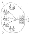
- FIG. 1 shows a radio network 100 with a radio cell 101 which is connected to a core network 102.
- the radio cell 101 there are a base station 103 and five mobile stations 104A to 104E.
- Each of the mobile stations 104 each has a unique identifier 105A to 105E.
- the base station 103 has a connection unit 106, a transmission scheduler 107 and a transmitting and receiving antenna 110.
- connection unit 106 data connections between the core network 102 and the mobile stations 104 are expanded and, if appropriate, data packets belonging to these connections are buffered.
- the transmission scheduler 107 based on available connection data such as a required data rate of an already established connection and the amount of data temporarily stored in the connection unit 106 for each of the mobile stations 104, creates a transmission plan for transmitting data from the connection unit 106 to one or a group from mobile stations 104.
- the transmission scheduler 107 may be a hardware component or a computer program executing on a processor of the base station 103 or a computer connected thereto. A combination of hardware and software components is possible.
- the transmission scheduler 107 When creating the transmission plan, the transmission scheduler 107 also takes into account the respective channel quality for each available transmission channel in each scheduled time slot of the transmission interval. Information about this is determined from static data, in particular from the mobile stations 104 back transmitted channel quality information, bit error rates or signal to noise ratios.
- Each of the mobile stations 104 has a receiving part 108 and a transmitting part 109. Both are connected to a combined transmit and receive antenna 110.
- the receiving section 108 is configured to monitor a plurality of channels of the radio cell 101 in order to recognize and filter out data packets with the unique identifier 105 of the respective mobile station 104.
- the unique identifier 105 or an independent key can also be used for decrypting encrypted data transmitted over the wireless network 100, so that each mobile Station 104 can decrypt only addressed to them data packets.
- the radio network 100 in the exemplary embodiment is a so-called OFDM radio network.
- the base station 103 and the mobile stations 104 are a base station of a cellular phone cell and cellular phones within the cell.
- it can also be other transmitters and receivers of a wireless network 100, for example, devices in a so-called wireless LAN (WLAN) data network.
- Characteristic of each of these radio networks 100 is that a plurality of transmission channels and time slots are available, so that the data transmission in both the time domain and in the frequency domain can be multiplexed, that is, both different transmission channels and different time slots individual mobile Stations 104 can be assigned.
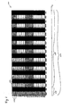
- FIG. 2 shows an exemplary transmission plan 200 for a transmission interval 201.
- the transmission interval 201 is divided into twenty time slots 202, also referred to as "frames".
- Odd-order time slots 202 serve to transfer data from the base station 103 to the mobile stations 104 and are designated 202P and 202A-202I.
- Even-numbered time slots 202 are used to transfer data from the mobile stations 104 back to the base station 103 and are in the FIG. 2 shaded.
- the transmission interval 201 is additionally subdivided into an optional measurement phase 205 and a data transmission phase 206.
- the measurement phase 205 includes a Time slot 202P in the downlink direction and another time slot 202 in the uplink direction and is used to determine channel characteristics.
- the data transmission phase 206 comprises the remaining 18 time slots 202 and serves to transmit user data.
- Each time slot 202 is additionally divided into a plurality of transmission channels 203.
- 20 transmission channels 203 are available for data transmission.
- the transmission channels 203 are, for example, different frequency ranges of a transmission band.
- information is transmitted to all mobile stations 104A-104E.
- a predetermined measurement signal may be transmitted from the base station 103 to the mobile stations 104.
- control information or other data may also be transmitted to the mobile stations 104A-104E.
- all mobile stations 104A to 104E which are located in a radio cell 101 and thus assigned to the base station 103, monitor the transmission channels 203 for information, in particular the measurement signal.
- the transmission channels 203 For example, a received power of the received measurement signal, a signal-to-noise ratio or a specific bit error rate can be used.
- these values or values derived therefrom which permit a determination of the channel quality, are transmitted from the mobile stations 104A to 104E back to the base station 103.
- a separate measurement phase 205 other means for determining channel properties may also be used. For example, in a previous transmission interval 201 or a data transmission phase 205, determined bit error rates can be used to estimate the channel quality and thus serve for planning the data transmission in the current transmission interval 201. In order to allow a particularly good assessment, the measurement phase 205 should be as close to the data transmission phase 206 as possible in terms of time.
- the transmission scheduler 107 of the base station 103 uses the channel properties determined to create the transmission plan 200 for the data transmission phase 206, which is stored in the FIG. 2 is shown. Accordingly, the three mobile stations 104A to 104C are served by the base station 103. Possible further receivers, for example further mobile stations 104D and 104E, are not taken into account during the data transmission phase 206 for which the transmission plan 200 was determined.
- connection unit 106 no data is available for transmission to a mobile station 104D, or error-free communication due to interference between the base station 103 and one mobile station 104E is impossible.
- the mobile stations 104D and 104E may turn off or suspend at least portions of their receiving sections 108, in particular signal processors used for decryption and further processing of received data packets 204, in order to reduce power consumption. In this way, extended runtimes of the mobile stations 104D and 104E are enabled while maintaining battery capacity.
- the idle state may also serve to accelerate other functions of the mobile station 104D or 104E, for example, in which more processor time is provided for other tasks.
- the communication layer 200 for the data transmission phase 206 can be made flexible by the base station 103 and its transmission scheduler 107, for example allowing different data transmission rates within the data transmission phase 206, as described in US Pat FIG. 2 is shown.
- the first mobile station 104A first receives data simultaneously on eight transmission channels 203. However, this relatively broadband data transmission occurs only for the duration of four time slots 202A-202D. Thereafter, no further data packets 204 are transmitted to the mobile station 104A. During the time slots 202A-202D, data is simultaneously transmitted to the mobile station 104B and the mobile station 104C on five and seven transmission channels 203, respectively.
- the mobile station 104A may also be switched to a sleep state until the end of the transmission interval 201.
- data transmission rates between the base station 103 and the different mobile stations 104A, 104B and 104C are adapted to current requirements and channel qualities. For example, if data transmission between the base station 103 and the mobile station 104A is possible only in the first time slots 202A-202D, because interference interferes with data transmission thereafter, data may initially be transmitted in relatively broadband so that the mobile station 104A may still be available during the subsequent radio pause cached data is available for further processing. Conversely, data transmissions to the mobile stations 104B and 104C are initially restricted to allow broadband data transmission to the mobile station 104A and subsequently extended to data temporarily latched in the connection unit 106 to the mobile stations 104B and 104C during the time slots 202E to 202I, respectively transfer.
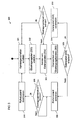
- FIG. 3 shows a flow diagram of a method 300 for transmitting data from a transmitter, such as base station 103, to a receiver, such as mobile station 104A, of a wireless network 100.
- the channel properties of the radio network 101 are determined. For example, these can be determined during a measurement phase 205 by transmitting a measurement signal to all mobile stations 204 of the radio network and subsequent return transmission of received services measured by the mobile stations 104. Alternatively, however, the channel characteristics may also be estimated from error rates of previous transmission intervals 201.
- the base station 103 creates a transmission plan 200 for the current transmission interval 201 or its data transmission phase 206.
- special requirements of the mobile stations 104 with regard to required data rates, real-time conditions or connection qualities can be taken into account.
- planning for the complete transmission interval 201 may also be omitted. For example, it is also possible to plan ahead only for a single or a few time slots 202 of the transmission interval 201, approximately in dependence on data buffered in the connection unit 106.
- data packets 204 are sent from the base station 103 to the mobile stations 104.
- user data provided by a connection unit 106 can be transmitted to the mobile stations 104.
- an identifier for example the unique identifier 105, is embedded in each of the data packets 204 so that a receiver 104 associated with the identifier can recognize data packets 204 directed to it.
- transmission plan 200 in time slot 202A data packets sent to the receivers 104A to 104C.
- all active mobile stations 104A-104E of a radio cell 101 of the radio network 100 monitor at least one of the transmission channels 203 for data packets 204 directed to them. This can be done, for example, by monitoring an identifier embedded in the data packets 204 and comparing it with a unique identifier 105 the mobile stations 104 are performed.
- a mobile station 104 is configured to simultaneously monitor all transmission channels 203. Due to technical limitations of the receiving section 108 and interference of individual transmission channels 203, however, it is also possible for only individual transmission channels 203 to be monitored by a mobile station 104.
- a further step 305 it is checked by each individual mobile station 104A to 104E whether during the preceding time slot 202 data packets 204 were transmitted to it from the base station 103. In the embodiment this is true in timeslot 202A for mobile stations 104A, 104B and 104C, but not for stations 104D and 104E.
- step 305 If it is determined in step 305 that at least one data packet 204 has been transmitted to the mobile stations 104A, the data received therein is processed in an optional step 306. For example, user data contained therein can be decrypted or reproduced.
- step 307 it is then checked whether the current time slot 202A was the last time slot of the current transmission interval 201. If this is not the case, the method is continued in step 303 with the next time slot 202B. Otherwise, the process begins again at step 301 with the determination of channel properties.
- step 308 a sleep state is activated for the mobile station 104A.
- a receiving section 108 of the mobile station 104 can be deactivated.
- a delay loop checks whether the end of the transmission interval 201 has been reached. During this time, the receiver 104A is in an idle state, so that its power consumption is reduced. Alternatively, the mobile station 104A may also preferably perform other tasks, such as internal data processing, at this time without paying attention to data packets 204 transmitted to it.
- the idle state is deactivated again in a step 310.
- the receiving section 108 of the mobile station 104A is available again in a subsequent measuring phase 205 or data transmission phase 206 of a subsequent transmission interval 201.
Abstract
Description
Die Erfindung betrifft ein Verfahren zum Übertragen von Daten in einem Übertragungsintervall mit mehreren Zeitschlitzen und mit mehreren Übertragungskanälen an einen Empfänger eines Funknetzwerkes mit einem Sender und wenigstens einem weiteren Empfänger.The invention relates to a method for transmitting data in a transmission interval with a plurality of time slots and with a plurality of transmission channels to a receiver of a radio network with a transmitter and at least one further receiver.
Die Erfindung betrifft außerdem ein Funknetzwerk und einen Empfänger, die zur Durchführung des Verfahrens eingerichtet sind.The invention also relates to a radio network and a receiver adapted to carry out the method.
Verfahren zum Übertragen von Daten in einem Funknetzwerk mit einem Sender und einer Vielzahl von Empfängern sind vielfach bekannt. Beispielsweise verwenden digitale Mobiltelefonfunknetzwerke Frequenzmultiplexverfahren (FDMA), Zeitmultiplexverfahren (TDMA) und Codemultiplexverfahren (CDMA) zur Übertragung von Daten an eine Vielzahl von Empfängern einer Funkzelle über eine gemeinsame Luftschnittstelle.Methods of transmitting data in a radio network with a transmitter and a plurality of receivers are well known. For example, digital cellular radio networks use frequency division multiplexing (FDMA), time division multiple access (TDMA) and code division multiple access (CDMA) techniques to transmit data to a plurality of receivers of a radio cell over a common air interface.
Weiterer Übertragungsverfahren sehen ein Multiplexen sowohl in der Zeit- als auch in der Frequenzdomain vor, beispielsweise eine Datenübertragung nach dem Enhanced Data Rates for GSM Evolution (EDGE) Standard oder bei dem so genannten Orthogonal Frequency Division Multiplexing (OFDM). Um bei OFDM-Systemen eine möglichst hohe Datenübertragungsrate und einen effizienten Umfang mit der zur Verfügung stehenden Bandbreite zu erreichen, werden die Übertragungseigenschaften einzelner, zueinander orthogonaler Kanäle zwischen einer Basisstation und einer Vielzahl von mobilen Stationen berücksichtigt und die Datenübertragung fortwährend an diese angepasst. Auf diese Weise werden für jeden Empfänger nur solche Kanäle verwendet, auf denen gute Empfangseigenschaften bestehen. Dieses Prinzip ist auch unter dem Namen "Multi User Diversity" (MUD) bekannt.Further transmission methods provide for multiplexing both in the time domain and in the frequency domain, for example data transmission according to the Enhanced Data Rates for GSM Evolution (EDGE) standard or in the so-called Orthogonal Frequency Division Multiplexing (OFDM). In order to achieve the highest possible data transmission rate and an efficient scope of the available bandwidth in OFDM systems, the transmission characteristics of individual, mutually orthogonal channels between a base station and a plurality of mobile stations are considered and the data transmission constantly adapted to this. In this way, only those channels are used for each receiver on which there are good reception properties. This principle is also known as "Multi User Diversity" (MUD).
Nachteilig an den bekannten Verfahren ist, dass die Planung der Verwendung von zur Verfügung stehenden Übertragungskanälen verhältnismäßig aufwendig ist und Empfänger ständig eine Vielzahl von Übertragungskanälen auf an sie gerichtete Daten überwachen müssen, was zu einem hohen Energiebedarf auf Seiten der Empfänger führt.A disadvantage of the known method is that the planning of the use of available transmission channels is relatively expensive and receiver must constantly monitor a variety of transmission channels directed to them data, resulting in a high energy demand on the part of the receiver.
Der Artikel "Changes on Downlink and Uplink Resource Allocation on OFDMA-PHY", IEEE C802.16E-04/07R1, 15.Januar 2004 beschreibt ein OFDM-Übertragungsverfahren, bei dem die Datenpakete in der Reihenfolge der Robustheit ihrer Burstprofile übertragen werden.The article "Changes on Downlink and Uplink Resource Allocation on OFDMA PHY", IEEE C802.16E-04 / 07R1, January 15, 2004 describes an OFDM transmission method in which the data packets are transmitted in the order of robustness of their burst profiles.
Aus 3GPP TR 25.814 V1.1.1, Februar 2006 ist ein OFDM-System bekannt, in welchem Messungen der Kanalqualität durch die Mobilstationen durchgeführt und an de Basisstation zurückgemeldet werden.From 3GPP TR 25.814 V1.1.1, February 2006, an OFDM system is known in which measurements of the channel quality are performed by the mobile stations and reported back to the base station.
Aufgabe der Erfindung ist es daher, ein Verfahren zum Übertragen von Daten in einem Funknetzwerk der oben genannten Art zu beschreiben, das flexibel ist und einen effizienten Einsatz der zur Verfügung gestellten Ressourcen erlaubt. Des Weiteren sollen ein Funknetzwerk und ein Empfänger beschrieben werden, die zur Durchführung eines solchen Verfahrens geeignet sind.The object of the invention is therefore to describe a method for transmitting data in a radio network of the type mentioned above, which is flexible and allows efficient use of the resources made available. Furthermore, a radio network and a receiver are described which are suitable for carrying out such a method.
Erfindungsgemäß wird die Aufgabe durch ein Verfahren der oben genannten Art mit den folgenden Schritten gelöst:
- Senden wenigstens eines Datenpaketes mit einer eingebetteten Kennung auf wenigstens einem Übertragungskanal in einem Zeitschlitz des Übertragungsintervalls durch den Sender,
- Überwachen des wenigstens eines Übertragungskanals durch den Empfänger auf in dem Zeitschlitz übertragene Datenpakete mit darin eingebetteten, dem Empfänger zugeordneten Kennungen und
- Schalten des Empfängers in einen Ruhezustand bis zum Ende des Übertragungsintervalls, wenn der Empfänger während des Zeitschlitzes kein Datenpaket mit einer darin eingebetteten, dem Empfänger zugeordneten Kennung erhalten hat.
- Transmitting at least one data packet with an embedded identifier on at least one transmission channel in a time slot of the transmission interval by the transmitter,
- Monitoring the at least one transmission channel by the receiver on in the time slot transmitted data packets embedded therein, the receiver associated identifiers and
- Switching the receiver to a sleep state until the end of the transmission interval, if the receiver has received during the time slot no data packet with an embedded therein, the receiver associated identifier.
Durch das Überwachen wenigstens eines Übertragungskanals in dem Zeitschlitz auf eine an einen Empfänger gerichtete Datenpakete können die Empfänger, die in dem Zeitschlitz keine Daten erhalten haben, für weitere Zeitschlitze des Übertragungsintervalls in einen Ruhezustand geschaltet werden. Des Weiteren wird durch das Einbetten einer einem Empfänger zugeordneten Kennung eine so genannte In-Band Signalisierung ermöglicht, so dass auf die Verwendung eines dedizierten Steuerkanals verzichtet werden kann.By monitoring at least one transmission channel in the time slot for a data packet directed to a receiver, the receivers that have not received data in the time slot may be put into an idle state for further time slots of the transmission interval. Furthermore, by embedding an identifier assigned to a receiver, a so-called in-band signaling is made possible, so that the use of a dedicated control channel can be dispensed with.
In einer vorteilhaften Ausgestaltung der Erfindung werden die Schritte des Verfahrens für jeden nachfolgenden Zeitschlitz des Übertragungsintervalls wiederholt, solange der Empfänger in einem vorherigen Zeitschlitz ein Datenpaket mit einer darin eingebetteten, dem Empfänger zugeordneten Kennungen erhalten hat. Auf diese Weise kann der Empfänger in den Ruhezustand geschaltet werden, sobald keine Datenübertragung an ihn mehr stattfindet.In an advantageous embodiment of the invention, the steps of the method for each subsequent time slot of the transmission interval are repeated as long as the receiver has received in a previous time slot a data packet with embedded therein, the receiver associated identifiers. In this way, the receiver can be switched to the idle state as soon as there is no data transmission to it.
In einer weiteren vorteilhaften Ausgestaltung der Erfindung werden in einem zusätzlichen Schritt Kanaleigenschaften des wenigstens eines Übertragungskanals in einer Messphase ermittelt. Durch das Ermitteln von Kanaleigenschaften kann eine Datenübertragung an die Empfänger des Funknetzwerkes unter Berücksichtigung der Übertragungseigenschaften geplant oder an diese angepasst werden.In a further advantageous embodiment of the invention, channel properties of the at least one transmission channel in a measurement phase are determined in an additional step. By determining channel properties, a data transmission to the receivers of the radio network can be planned or adapted taking into account the transmission characteristics.
In einer weiteren vorteilhaften Ausgestaltung der Erfindung werden vorbestimmte Anforderungen für Datenraten, Echtzeitbedingungen oder Verbindungsqualitäten bei der Ermittlung eines Übertragungsplanes für das Übertragungsintervall berücksichtigt, so dass verbindungsspezifische Qualitätsanforderungen eingehalten werden können.In a further advantageous embodiment of the invention, predetermined requirements for data rates, real-time conditions or connection qualities in the determination of a transmission plan for the transmission interval are taken into account, so that connection-specific quality requirements can be met.
Weitere Ausgestaltungen der Erfindung sind in den Unteransprüchen angegeben. Die Erfindung wird nachfolgend an einem Ausführungsbeispiel anhand der Zeichnungen näher erläutert. In den Zeichnungen zeigen:
Figur 1- ein Funknetzwerk gemäß einer Ausgestaltung der Er- findung,
- Figur 2
- eine schematische Darstellung eines Übertragungs- plans,
- Figur 3
- ein Flussdiagram eines Verfahrens zum Übertragen von Daten.
- FIG. 1
- a radio network according to an embodiment of the invention,
- FIG. 2
- a schematic representation of a transmission plan,
- FIG. 3
- a flow chart of a method for transmitting data.
Die Basisstation 103 weist eine Verbindungseinheit 106, einen Übertragungsplaner 107 und eine Sende- und Empfangsantenne 110 auf. Durch die Verbindungseinheit 106 werden Datenverbindungen zwischen dem Kernnetzwerk 102 und den mobilen Stationen 104 ausgebaut und zu diesen Verbindungen gehörende Datenpakete gegebenenfalls zwischengespeichert.The
Der Übertragungsplaner 107 erstellt anhand zur Verfügung stehender Verbindungsdaten, wie etwa eine erforderlichen Datenrate einer bereits aufgebauten Verbindung und der Menge in der Verbindungseinheit 106 für jede der mobilen Stationen 104 zwischengespeicherten Daten, einen Übertragungsplan zur Übertragung von Daten aus der Verbindungseinheit 106 an eine oder eine Gruppe von mobilen Stationen 104. Bei dem Übertragungsplaner 107 kann es sich um eine Hardwarekomponente oder eine Computerprogramm handeln, dass auf einem Prozessor der Basisstation 103 oder einem damit verbundenen Rechner ausgeführt wird. Auch eine Kombination von Hard- und Softwarekomponenten ist möglich.The
Bei der Erstellung des Übertragungsplans berücksichtigt der Übertragungsplaner 107 auch die jeweilige Kanalqualität für jeden zur Verfügung stehenden Übertragungskanal in jedem geplanten Zeitschlitz des Übertragungsintervalls. Informationen hierzu werden aus statischen Daten ermittelt, insbesondere von den mobilen Stationen 104 zurück übermittelten Kanalqualitätsinformationen, Bitfehlerraten oder Rauschabständen.When creating the transmission plan, the
Jede der mobilen Stationen 104 weist einen Empfangsteil 108 und einen Sendeteil 109 auf. Beide sind mit einer kombinierten Sende- und Empfangsantenne 110 verbunden. Der Empfangsteil 108 ist dazu eingerichtet, eine Vielzahl von Kanälen der Funkzelle 101 zu überwachen, um Datenpakete mit der eindeutigen Kennung 105 der jeweiligen mobilen Station 104 zu erkennen und heraus zu filtern. Dabei kann die eindeutige Kennung 105 oder ein davon unabhängiger Schlüssel auch zur Entschlüsselung von verschlüsselt über das Funknetzwerk 100 übertragenden Daten verwendet werden, so dass jede mobile Station 104 nur an sie gerichtete Datenpakete entschlüsseln kann.Each of the
Bei dem Funknetzwerk 100 handelt es sich im Ausführungsbeispiel um ein so genanntes OFDM-Funknetzwerk. Beispielsweise handelt es sich bei der Basisstation 103 und den mobilen Stationen 104 um eine Basisstation einer Mobiltelefonfunkzelle und Mobiltelefone innerhalb der Zelle. Selbstverständlich kann es sich auch um andere Sender und Empfänger eines Funknetzwerkes 100 handeln, beispielsweise um Geräte in einem so genannten Wireless LAN (WLAN) Datennetzwerk. Kennzeichnend für jedes dieser Funknetzwerke 100 ist es, dass eine Vielzahl von Übertragungskanälen und Zeitschlitzen zur Verfügung stehen, so dass die Datenübertragung sowohl in der Zeitdomain als auch in der Frequenzdomain gemultiplext werden kann, das heißt, dass sowohl unterschiedliche Übertragungskanäle als auch unterschiedliche Zeitschlitze einzelnen mobilen Stationen 104 zugewiesen werden können.The radio network 100 in the exemplary embodiment is a so-called OFDM radio network. For example, the
Im Ausführungsbeispiel ist das Übertragungsintervall 201 zusätzlich in eine optionale Messphase 205 und eine Datenübertragungsphase 206 unterteilt. Die Messphase 205 umfasst einen Zeitschlitz 202P in Downlink-Richtung und einen weiteren Zeitschlitz 202 in Uplink-Richtung und wird zur Ermittlung von Kanaleigenschaften verwendet. Die Datenübertragungsphase 206 umfasst die verbleibenden 18 Zeitschlitze 202 und dient der Übertragung von Nutzdaten.In the exemplary embodiment, the
Für die Datenübertragungsphase 206 gelten dabei folgende Randbedingungen:
- Ein Empfänger, beispielsweise eine
mobile Station 104, der in einem aktuellenZeitschlitz 202 keine Daten von einem Sender, beispielsweise derBasisstation 103, erhalten hat, wird auch in keinem der nachfolgenden Zeitschlitze 202 Daten erhalten und kann daher für diese Dauer in einen Ruhezustand geschaltet werden. - Ein Empfänger, dessen Datenempfang in
dem aktuellen Zeitschlitz 202 abbricht, wird in keinem der nachfolgenden Zeitschlitze 202 berücksichtigt und kann daher ebenfalls für die Dauer desÜbertragungsintervalls 201 in einen Ruhezustand geschaltet werden. - Jeder Empfänger kann in
jedem nachfolgenden Zeitschlitz 202 mehr oder weniger Übertragungskanäle 203 zugewiesen bekommen.
- A receiver, for example a
mobile station 104, which has not received any data from a transmitter, for example thebase station 103, in acurrent time slot 202 will not receive data in any of thesubsequent time slots 202 and therefore can be switched to an idle state for that duration , - A receiver whose data reception aborts in the
current time slot 202 is not taken into account in any of thesubsequent time slots 202 and can therefore also be switched to an idle state for the duration of thetransmission interval 201. - Each receiver may be assigned more or
less transmission channels 203 in eachsuccessive time slot 202.
Für die weitere Beschreibung wird nur die Datenübertragung von der Basisstation 103 zu den mobilen Stationen 104 näher beschrieben. Selbstverständlich ist eine Anwendung des Verfahrens gemäß der vorliegenden Erfindung auch für die Rückübertragung von den mobilen Stationen 104 zu der Basisstation 103 anwendbar.For the further description, only the data transmission from the
Jeder Zeitschlitz 202 ist zusätzlich in eine Vielzahl von Übertragungskanälen 203 aufgeteilt. Im Ausführungsbeispiel stehen 20 Übertragungskanäle 203 zur Datenübertragung zur Verfügung. Bei den Übertragungskanälen 203 handelt es sich beispielsweise um unterschiedliche Frequenzbereiche eines Übertragungsbandes.Each
Während der Messphase 205, im dargestellten Übertragungsplan 200 entsprechend dem ersten Zeitschlitz 202P, werden Informationen an sämtliche mobilen Stationen 104A bis 104E übertragen. Beispielsweise kann ein vorbestimmtes Messsignal von der Basisstation 103 an die mobilen Stationen 104 übertragen werden. Alternativ können auch Steuerinformationen oder sonstige Daten an die mobilen Stationen 104A bis 104E übertragen werden.During the
Während dieser Messphase überwachen sämtliche mobilen Stationen 104A bis 104E, die sich in einer Funkzelle 101 befinden und damit der Basisstation 103 zugeordnet sind, die Übertragungskanäle 203 auf Informationen, insbesondere das Messsignal. Zur Ermittlung von Kanaleigenschaften kann beispielsweise eine Empfangsleistung des empfangenen Messsignals, ein Rauschabstand oder eine spezifische Bitfehlerrate dienen. Im nachfolgenden Zeitschlitz 202 werden diese oder daraus abgeleitete Werte, die eine Bestimmung der Kanalqualität zulassen, von den mobilen Stationen 104A bis 104E zurück zur Basisstation 103 übermittelt.During this measurement phase, all mobile stations 104A to 104E, which are located in a
Alternativ zu einer gesonderten Messphase 205 können auch andere Mittel zur Ermittlung von Kanaleigenschaften Verwendung finden. Beispielsweise können in einem vorherigen Übertragungsintervall 201 bzw. einer Datenübertragungsphase 205 ermittelte Bitfehlerraten zur Einschätzung der Kanalqualität und somit zur Planung der Datenübertragung in dem aktuellen Übertragungsintervall 201 dienen. Um eine besonders gute Einschätzung zu ermöglichen, sollte die Messphase 205 zeitlich möglichst dicht an der Datenübertragungsphase 206 liegen.As an alternative to a
Der Übertragungsplaner 107 der Basisstation 103 erstellt anhand der ermittelten Kanaleigenschaften den Übertragungsplan 200 für die Datenübertragungsphase 206, der in der
Dies kann zum einen daran liegen, dass nicht genug Übertragungskapazität zur Bedienung sämtlicher mobiler Stationen 104 zur Verfügung steht, in der Verbindungseinheit 106 keine Daten zur Übermittlung an eine mobile Station 104D zur Verfügung stehen oder eine fehlerfreie Kommunikation aufgrund von Interferenz zwischen der Basisstation 103 und einer mobilen Station 104E unmöglich ist.This may be due to the fact that there is not enough transmission capacity available to service all
In all diesen Fällen können die mobilen Stationen 104D und 104E zumindest Teile ihrer Empfangsteile 108, insbesondere zur Entschlüsselung und Weiterverarbeitung empfangener Datenpakete 204 genutzte Signalprozessoren ausschalten beziehungsweise in einen Ruhezustand schalten, um die Leistungsaufnahme zu verringern. Auf diese Weise werden verlängerte Laufzeiten der mobilen Stationen 104D und 104E bei gleich bleibender Batteriekapazität ermöglicht. Alternativ zu einer Energieeinsparung kann der Ruhezustand auch dazu dienen, andere Funktionen der mobilen Station 104D beziehungsweise 104E zu beschleunigen, etwa in dem mehr Prozessorzeit für andere Aufgaben bereitgestellt wird.In all these cases, the mobile stations 104D and 104E may turn off or suspend at least portions of their receiving
Trotz dieser Beschränkungen und Vereinfachung auf Seiten der mobilen Stationen 104 kann der Übertragungsplan 200 für die Datenübertragungsphase 206 von der Basisstation 103 und dessen Übertragungsplaner 107 flexibel gestaltet werden, so dass beispielsweise unterschiedliche Datenübertragungsraten innerhalb der Datenübertragungsphase 206 ermöglicht werden, wie dies in der
Im dargestellten Beispiel empfängt die erste mobile Station 104A zunächst auf acht Übertragungskanälen 203 gleichzeitig Daten. Diese verhältnismäßig breitbandige Datenübertragung findet jedoch nur für die Dauer von vier Zeitschlitzen 202A bis 202D statt. Danach werden keine weiteren Datenpakete 204 an die mobile Station 104A übertragen. Während der Zeitschlitze 202A bis 202D werden gleichzeitig auf fünf beziehungsweise sieben Übertragungskanälen 203 Daten an die mobile Station 104B beziehungsweise die mobile Station 104C übertragen.In the illustrated example, the first mobile station 104A first receives data simultaneously on eight
Ab dem Zeitschlitz 202E werden ausschließlich Daten an die mobilen Stationen 104B und 104C übertragen, so dass für die Datenübertragung ab diesem Zeitschlitz 202E acht beziehungsweise zwölf Übertragungskanäle 203 zur Verfügung stehen. Weil die mobile Station 104A in dem Übertragungsintervall 202E keine weiteren Daten von der Basisstation 103 empfängt, kann auch sie bis zum Ende des Übertragungsintervalls 201 in einen Ruhezustand geschaltet werden.From the
Auf diese Weise können Datenübertragungsraten zwischen der Basisstation 103 und den unterschiedlichen mobilen Stationen 104A, 104B und 104C an aktueller Erfordernisse und Kanalqualitäten angepasst werden. Ist beispielsweise eine Datenübertragung zwischen der Basisstation 103 und der mobilen Station 104A nur in den ersten Zeitschlitzen 202A bis 202D möglich, weil danach Interferenz eine Datenübertragung stört, können Daten zunächst relativ breitbandig übertragen werden, so dass die mobile Station 104A während der nachfolgenden Funkpause noch eventuell zwischengespeicherte Daten zur weiteren Verarbeitung zur Verfügung stehen. Umgekehrt werden Datenübertragungen zu den mobilen Stationen 104B und 104C zunächst beschränkt, um eine breitbandige Datenübertragung zu der mobilen Station 104A zu ermöglichen und nachher erweitert um gegebenenfalls in der Verbindungseinheit 106 zwischenzeitlich zwischengespeicherte Daten an die mobile Station 104B und 104C während der Zeitschlitze 202E bis 202I zu übertragen.In this way, data transmission rates between the
Zunächst werden in einem optionalen Schritt 301 die Kanaleigenschaften des Funknetzwerks 101 ermittelt. Beispielsweise können diese während einer Messphase 205 durch Übermitteln eines Messsignals an alle mobilen Stationen 204 des Funknetzwerkes und nachfolgenden Rückübermittlung von durch die mobilen Stationen 104 gemessenen Empfangsleistungen ermittelt werden. Alternativ können die Kanaleigenschaften aber auch aus Fehlerraten vorhergehender Übertragungsintervalle 201 geschätzt werden.First, in an
In einem weiteren optionalen Schritt 302 erstellt die Basisstation 103 einen Übertragungsplan 200 für das aktuelle Übertragungsintervall 201 oder dessen Datenübertragungsphase 206. Darin können insbesondere besondere Anforderungen der mobilen Stationen 104 bezüglich benötigter Datenraten, Echtzeitbedingungen oder Verbindungsqualitäten berücksichtigt werden.In a further
Alternativ kann eine Planung für das komplette Übertragungsintervall 201 jedoch auch entfallen. Beispielsweise ist es auch möglich, nur für einen einzelnen oder wenige Zeitschlitze 202 des Übertragungsintervalls 201 vorauszuplanen, in etwa in Abhängigkeit von in der Verbindungseinheit 106 gepufferten Daten.Alternatively, however, planning for the
In einem weiteren Schritt 303 werden Datenpakete 204 von der Basisstation 103 an die mobilen Stationen 104 gesendet. Beispielsweise können von einer Verbindungseinheit 106 zur Verfügung gestellte Nutzdaten an die mobilen Stationen 104 übertragen werden. Dazu wird eine Kennung, beispielsweise die eindeutige Kennung 105, in jedes der Datenpakete 204 eingebettet, so dass ein der Kennung zugeordneter Empfänger 104 an ihn gerichtete Datenpakete 204 erkennen kann. Im Ausführungsbeispiel werden gemäß dem in
In einem Schritt 304 überwachen alle aktiven mobilen Stationen 104A bis 104E einer Funkzelle 101 des Funknetzwerkes 100 wenigstens einen der Übertragungskanäle 203 auf an sie gerichtete Datenpakete 204. Dies kann zum Beispiel durch Überwachung einer in die Datenpakete 204 eingebettete Kennung und Vergleich mit einer eindeutigen Kennung 105 der mobilen Stationen 104 durchgeführt werden.In a step 304, all active mobile stations 104A-104E of a
In einer bevorzugten Ausgestaltung ist eine mobile Station 104 dazu eingerichtet, sämtliche Übertragungskanäle 203 gleichzeitig zu überwachen. Aufgrund von technischen Beschränkungen des Empfangsteils 108 und Störungen einzelner Übertragungskanäle 203 ist es jedoch auch möglich, dass nur einzelne Übertragungskanäle 203 durch eine mobile Station 104 überwacht werden.In a preferred embodiment, a
In einem weiteren Schritt 305 wird von jeder einzelnen mobilen Station 104A bis 104E überprüft, ob während des vorausgehenden Zeitschlitzes 202 Datenpakete 204 von der Basisstation 103 an sie übertragen wurden. Im Ausführungsbeispiel trifft dies im Zeitschlitz 202A für die mobilen Stationen 104A, 104B und 104C zu, nicht jedoch für die Stationen 104D und 104E.In a
Wird im Schritt 305 festgestellt, dass wenigstens ein Datenpaket 204 an die mobile Stationen 104A übertragen wurden, werden die darin erhaltenen Daten in einem optionalen Schritt 306 verarbeitet. Beispielsweise können darin enthaltenen Nutzdaten entschlüsselt oder wiedergegeben werden.If it is determined in
In einem weiteren Schritt 307 wird dann überprüft, ob der aktuelle Zeitschlitz 202A der letzte Zeitschlitz des aktuellen Übertragungsintervalls 201 war. Ist dies nicht der Fall, wird das Verfahren im Schritt 303 mit dem nächsten Zeitschlitz 202B fortgesetzt. Andernfalls beginnt das Verfahren erneut mit Schritt 301 mit der Ermittlung von Kanaleigenschaften.In a
Alternativ ist es auch möglich, die Kanaleigenschaften nach jedem Zeitschlitz 202 neu zu ermitteln. Dazu können beispielsweise die in der
Wird im Schritt 305 jedoch festegestellt, dass kein Datenpaket an die mobile Station 104A übertragen wurde, wie dies beispielsweise im fünften Zeitschlitz 202E der Fall ist, wird in einem Schritt 308 ein Ruhezustand für die mobile Station 104A aktiviert. Beispielsweise kann ein Empfangsteil 108 der mobilen Station 104 deaktiviert werden.However, if it is determined in
Im Schritt 309 überprüft eine Verzögerungsschleife, ob das Ende des Übertragungsintervalls 201 erreicht wurde. Während dieser Zeit befindet sich der Empfänger 104A in einem Ruhezustand, so dass dessen Energieaufnahme verringert ist. Alternativ kann die mobile Station 104A zu dieser Zeit auch bevorzugt andere Aufgaben wie etwa eine interne Datenverarbeitung ausführen ohne weiter auf an sie übertragenen Datenpakete 204 zu achten.In
Am Ende des Übertragungsintervalls 201 wird in einem Schritt 310 der Ruhezustand wieder deaktiviert. Somit steht beispielsweise das Empfangsteil 108 der mobilen Station 104A in einer darauf folgenden Messphase 205 oder Datenübertragungsphase 206 eines nachfolgenden Übertragungsintervalls 201 wieder zur Verfügung.At the end of the
- 100100
- FunknetzwerkWireless Network
- 101101
- Funkzelleradio cell
- 102102
- KernnetzwerkCore network
- 103103
- Basisstationbase station
- 104104
- Mobile StationMobile Station
- 105105
- Eindeutige KennungUnique identifier
- 106106
- Verbindungseinheitconnecting unit
- 107107
- Übertragungsplanertransmission scheduler
- 108108
- Empfangsteilreceive part
- 109109
- Sendeteilsending part
- 110110
- Sende- und EmpfangsantenneTransmitting and receiving antenna
- 200200
- Übertragungsplantransfer plan
- 201201
- Übertragungsintervalltransmission interval
- 202202
- Zeitschlitztime slot
- 203203
- Übertragungskanaltransmission channel
- 204204
- Datenpaketdata packet
- 205205
- Messphasemeasuring phase
- 206206
- DatenübertragungsphaseData transfer phase
- 300300
- Verfahren zum Übertragen von DatenMethod for transmitting data
- 301 - 310301 - 310
- Verfahrensschrittesteps
Claims (12)
- A method of transmitting data in a transmission interval (201) with several time slots (202) and with several transmission channels (203) to a receiver (1 04A) of a radio network (100) with a transmitter (103) and at least one further receiver (104B), the method comprising the steps:- sending at least one data packet (204) with an embedded identifier (105) on at least one transmission channel (203) in a time slot (202A) of the transmission interval (201) by the transmitter (103),- monitoring the at least one transmission channel (203) by the receiver (104A) on data packets (204) transmitted in the time slot (202A) with identifiers (105) embedded therein and associated with the receiver (1 04A) and- switching the receiver (104A) into an idle state until the end of the transmission interval (201), if the receiver (104A) has not received a data packet (204) with an identifier (105A) embedded therein and associated with the receiver (1 04A) during the time slot.
- The method according to claim 1, characterised in that the steps of the method are repeated for a subsequent time slot (202) of the transmission interval (201) as long as the receiver (104A) has received a data packet (204) with an identifier (1 05A) embedded therein and associated with the receiver (104A) in a previous time slot (202).
- The method according to claim 1 or 2, comprising the additional step:- determining channel characteristics of the at least one transmission channel (203) in a measuring phase (205).
- The method according to claim 3, characterised in that the step of determining channel characteristics comprises the following steps:- sending a pre-determined measurement signal from the transmitter (103) to the receiver (104A),- determining the reception quality of the measurement signal by the receiver (1 04A) and- conveying at least one value based on the reception quality, which permits a statement about channel characteristics, from the receiver (104A) to the transmitter (103).
- The method according to claim 3 or 4, comprising the additional step:- determining a transmission plan (200) for the transmission interval (201) based on channel characteristics determined in the measuring phase (205) of the at least one transmission channel (203).
- The method according to claim 5, characterised in that predetermined requirements for data rates, real time conditions or connection qualities of the receiver (1 04A) are considered during the determination of the transmission plan (200).
- A portable radio network (100) having a plurality of transmission channels (203), which are divided into a plurality of time slots (202) in a transmission interval (201), the portable radio network comprising- a transmitter (103) for transmitting data packets (204), wherein the transmitter (103) is adapted to transmit at least one data packet (204) with an embedded identifier (105) on at least one transmission channel (203) of the plurality of transmission channels (203) in a time slot (202A) of the transmission interval (201),- a receiver (1 04A) and at least one further receiver (104B, 104C, 104D, 104E) for receiving data packets (204) addressed to them, wherein the receivers (104, 104B, 104C, 104D, 104E) are adapted to simultaneously monitor the transmission channels (203), wherein the receiver (1 04A) is adapted to monitor at least one transmission channel (203) on data packets (204) transmitted in the time slot (202A) with identifiers (105) embedded therein and associated with the receiver (104A), and is adapted to switch into an idle state until the end of the transmission interval (201), if the receiver (104A) has not received a data packet (204) with an identifier (1 05A) embedded therein and associated with the receiver (1 04A) during the time slot (202).
- The radio network (100) according to claim 7, characterised in that- in a first time slot (202A) of the transmission interval (201), data packets (204) are exclusively transmitted to receivers (104A, 104B, 104C) of a selected group of the plurality of receivers (104),- in subsequent time slots (202B-2021) of the transmission interval (201), data packets (204) are exclusively transmitted to the receivers (1 04A, 104B, 104C) of the selected group and other receivers (104D, 104E) are switched into an idle state during the subsequent time slots (202B-202I).
- The radio network (100) according to claim 7 or 8, characterised in that the radio network (100) is an orthogonal frequency division multiplexing radio network.
- A receiver (1 04A) for use in a radio network (100) having a plurality of transmission channels (203), that are divided into a plurality of time slots (202) in a transmission interval (201), the receiver having a high frequency receiving section and a signal processing section, wherein in an idle state of the receiver at least the signal processing section may be switched into a sleep state, and the receiver (1 04A) is adapted- to receive at least one data packet (204) with an embedded identifier (105) on at least one transmission channel (203) in a time slot (202A) of the transmission channel (201),- to monitor the at least one transmission channel (203) on data packets transmitted in the time slot (202A) with identifiers (105) embedded therein and associated with the receiver (1 04A), and- to switch into an idle state until the end of the transmission interval (201), if the receiver (104A) has not received a data packet (204) with an identifier (105A) embedded therein and associated with the receiver (104A).
- The receiver according to claim 10, characterised in that the receiver (104A) has a transmitting section (109) for the transmission of data to the transmitter (103) and the receiver (104) is adapted to convey channel-specific reception characteristics, in particular data transmission rates or signal-to-noise ratios via the transmitting section (109) back to the transmitter (103).
- The receiver according to claim 10 or 11, characterised in that the receiver (104) is adapted to determine channel characteristics from a measurement signal transmitted by the transmitter (103).
Applications Claiming Priority (2)
| Application Number | Priority Date | Filing Date | Title |
|---|---|---|---|
| DE102006021100A DE102006021100A1 (en) | 2006-05-05 | 2006-05-05 | Method for transmitting data in a radio network, radio network and receiver |
| PCT/EP2007/054352 WO2007128793A2 (en) | 2006-05-05 | 2007-05-04 | Method for transmitting data in a radio network, radio network and receiver |
Publications (2)
| Publication Number | Publication Date |
|---|---|
| EP2018743A2 EP2018743A2 (en) | 2009-01-28 |
| EP2018743B1 true EP2018743B1 (en) | 2010-07-07 |
Family
ID=38437702
Family Applications (1)
| Application Number | Title | Priority Date | Filing Date |
|---|---|---|---|
| EP07728805A Not-in-force EP2018743B1 (en) | 2006-05-05 | 2007-05-04 | Energy efficient data transmission in a radio network |
Country Status (5)
| Country | Link |
|---|---|
| US (2) | US8208417B2 (en) |
| EP (1) | EP2018743B1 (en) |
| AT (1) | ATE473571T1 (en) |
| DE (2) | DE102006021100A1 (en) |
| WO (1) | WO2007128793A2 (en) |
Families Citing this family (3)
| Publication number | Priority date | Publication date | Assignee | Title |
|---|---|---|---|---|
| DE102006021100A1 (en) * | 2006-05-05 | 2007-11-08 | Benq Mobile Gmbh & Co. Ohg | Method for transmitting data in a radio network, radio network and receiver |
| DE102008018871B4 (en) * | 2008-04-14 | 2010-10-07 | Atmel Automotive Gmbh | Receiver circuit, method for receiving a signal and use of a detection circuit and a control circuit |
| US20150012367A1 (en) * | 2013-07-02 | 2015-01-08 | Facebook, Inc. | Fixed-pricing for guaranteed delivery of online advertisements |
Family Cites Families (18)
| Publication number | Priority date | Publication date | Assignee | Title |
|---|---|---|---|---|
| US4979170A (en) * | 1988-01-19 | 1990-12-18 | Qualcomm, Inc. | Alternating sequential half duplex communication system |
| US4928274A (en) * | 1988-01-19 | 1990-05-22 | Qualcomm, Inc. | Multiplexed address control in a TDM communication system |
| US5089813A (en) * | 1989-07-19 | 1992-02-18 | Motorola, Inc. | Method of super battery saving in a selective call receiver |
| JP2872057B2 (en) * | 1994-11-24 | 1999-03-17 | 日本電気株式会社 | Radio selective call receiver |
| US5978366A (en) * | 1996-12-20 | 1999-11-02 | Ericsson Inc. | Methods and systems for reduced power operation of cellular mobile terminals |
| US6515976B1 (en) * | 1998-04-06 | 2003-02-04 | Ericsson Inc. | Demodulation method and apparatus in high-speed time division multiplexed packet data transmission |
| US6816736B2 (en) * | 2001-01-08 | 2004-11-09 | Lucent Technologies Inc. | Apparatus and method for use in paging mode in wireless communications systems |
| US7170861B2 (en) * | 2001-07-31 | 2007-01-30 | Texas Instruments Incorporated | Distributed device identifier numbering and total device counting algorithm with smart time division multiplexed serial port |
| US7061879B2 (en) * | 2001-08-10 | 2006-06-13 | Motorola, Inc. | Method and apparatus for extending communication unit battery life |
| US7269145B2 (en) * | 2001-12-20 | 2007-09-11 | Samsung Electronics Co., Ltd. | Mode transition method for wireless data service in a mobile station |
| US7689196B2 (en) * | 2002-06-26 | 2010-03-30 | Qualcomm Incorporated | Timer-based sleep for terminals in wireless communication systems |
| KR100686775B1 (en) * | 2003-11-07 | 2007-02-23 | 삼성전자주식회사 | Method for transmitting traffic a indication message in broadband wireless access communication system |
| CN100474801C (en) | 2003-11-07 | 2009-04-01 | 上海贝尔阿尔卡特股份有限公司 | Spare mode control method in orthogonal FDM system |
| US8018969B2 (en) * | 2004-03-12 | 2011-09-13 | Samsung Electronics Co., Ltd | Method and apparatus for constructing MAP IE using reduced CID in broadband OFDMA systems |
| JP2006019850A (en) * | 2004-06-30 | 2006-01-19 | Hitachi Ltd | Wireless communication method, wireless communication base station, and wireless communication terminal |
| US8441971B2 (en) * | 2004-12-21 | 2013-05-14 | Intel Corporation | Idle state management |
| DE102006021100A1 (en) * | 2006-05-05 | 2007-11-08 | Benq Mobile Gmbh & Co. Ohg | Method for transmitting data in a radio network, radio network and receiver |
| US8797933B2 (en) * | 2010-12-27 | 2014-08-05 | Via Telecom Co., Ltd. | Apparatuses and methods for saving power in paging operations |
-
2006
- 2006-05-05 DE DE102006021100A patent/DE102006021100A1/en not_active Ceased
-
2007
- 2007-05-04 US US12/299,423 patent/US8208417B2/en not_active Expired - Fee Related
- 2007-05-04 DE DE502007004333T patent/DE502007004333D1/en active Active
- 2007-05-04 EP EP07728805A patent/EP2018743B1/en not_active Not-in-force
- 2007-05-04 AT AT07728805T patent/ATE473571T1/en active
- 2007-05-04 WO PCT/EP2007/054352 patent/WO2007128793A2/en active Application Filing
-
2012
- 2012-06-20 US US13/528,588 patent/US20120320777A1/en not_active Abandoned
Also Published As
| Publication number | Publication date |
|---|---|
| US20120320777A1 (en) | 2012-12-20 |
| DE102006021100A1 (en) | 2007-11-08 |
| US8208417B2 (en) | 2012-06-26 |
| WO2007128793A2 (en) | 2007-11-15 |
| EP2018743A2 (en) | 2009-01-28 |
| DE502007004333D1 (en) | 2010-08-19 |
| US20100008239A1 (en) | 2010-01-14 |
| WO2007128793A3 (en) | 2008-01-24 |
| ATE473571T1 (en) | 2010-07-15 |
Similar Documents
| Publication | Publication Date | Title |
|---|---|---|
| DE602004012092T2 (en) | MEDIA ACCESS CONTROL IN MASTER SLAVE SYSTEMS | |
| DE102005041273B4 (en) | A method of computer-aided forming of system information medium access control log messages, medium access control unit and computer program element | |
| DE19800953C1 (en) | Resource allocation in radio interface of radio communications system | |
| DE10393174B4 (en) | Dedicated high priority access channel | |
| DE602005005795T2 (en) | INTERRUPTED SENDING AND RECEIVING MULTIMEDIA BROADCAST / MULTICAST SERVICE DATA IN A MOBILE COMMUNICATION SYSTEM | |
| DE112018006458T5 (en) | COMMUNICATION DEVICE, COMMUNICATION METHOD AND COMMUNICATION SYSTEM | |
| DE60114768T2 (en) | DIGITAL COMMUNICATION SYSTEM | |
| DE112016002714T5 (en) | Enable the coexistence of long-term development and WiFi | |
| DE102013022493B3 (en) | MOBILE WIRELESS DEVICES AND METHODS OF OPERATION | |
| DE102017011009A1 (en) | COORDINATED BASE SERVICE GROUP COMMUNICATION (BSS COMMUNICATION) WITH PRO RANGE OF DIFFERENT MODULATION CODING SCHEME (MCS) | |
| DE112013001872T5 (en) | Method and apparatus for CSI feedback in a wireless communication system | |
| DE202006001027U1 (en) | Non-hierarchical wireless communication system | |
| DE112014004464B4 (en) | System and method for selectively preventing the transmission of a scheduling request | |
| DE112012005907B4 (en) | Communication system, communication terminal and communication method | |
| DE102010036590A1 (en) | A method for coordinating transmission and reception operations of radio modules in a communication device and communication device therefor | |
| DE602004007189T2 (en) | A method and apparatus for providing different resource access levels on a high-speed radio packet data network by providing an adaptive inactivity timer | |
| DE112017004083T5 (en) | SYSTEM AND METHOD FOR MULTIMEDIA BROADCAST MULTICAST SERVICE (MBMS) COUNTER OPERATION | |
| DE69935271T2 (en) | Method, device, and wireless communication controller | |
| DE102015110330A1 (en) | Method for energy saving and power saving for a mobile device | |
| DE102020112344A1 (en) | DYNAMIC PROCESSING RESOURCE ALLOCATION ACROSS MULTIPLE CARRIERS | |
| EP2018743B1 (en) | Energy efficient data transmission in a radio network | |
| DE10014396C2 (en) | Method for resource allocation in a radio communication system and radio communication system for performing the method | |
| EP1958477A1 (en) | Handoff preparation method in a wireless communication system | |
| EP1586206B1 (en) | Method for performing synchronization in radio communications systems | |
| DE60320111T2 (en) | Method of managing a common transmission medium |
Legal Events
| Date | Code | Title | Description |
|---|---|---|---|
| PUAI | Public reference made under article 153(3) epc to a published international application that has entered the european phase |
Free format text: ORIGINAL CODE: 0009012 |
|
| 17P | Request for examination filed |
Effective date: 20081201 |
|
| AK | Designated contracting states |
Kind code of ref document: A2 Designated state(s): AT BE BG CH CY CZ DE DK EE ES FI FR GB GR HU IE IS IT LI LT LU LV MC MT NL PL PT RO SE SI SK TR |
|
| AX | Request for extension of the european patent |
Extension state: AL BA HR MK RS |
|
| 17Q | First examination report despatched |
Effective date: 20090401 |
|
| DAX | Request for extension of the european patent (deleted) | ||
| GRAP | Despatch of communication of intention to grant a patent |
Free format text: ORIGINAL CODE: EPIDOSNIGR1 |
|
| RTI1 | Title (correction) |
Free format text: ENERGY EFFICIENT DATA TRANSMISSION IN A RADIO NETWORK |
|
| GRAS | Grant fee paid |
Free format text: ORIGINAL CODE: EPIDOSNIGR3 |
|
| GRAA | (expected) grant |
Free format text: ORIGINAL CODE: 0009210 |
|
| AK | Designated contracting states |
Kind code of ref document: B1 Designated state(s): AT BE BG CH CY CZ DE DK EE ES FI FR GB GR HU IE IS IT LI LT LU LV MC MT NL PL PT RO SE SI SK TR |
|
| REG | Reference to a national code |
Ref country code: GB Ref legal event code: FG4D Free format text: NOT ENGLISH |
|
| REG | Reference to a national code |
Ref country code: CH Ref legal event code: EP |
|
| REG | Reference to a national code |
Ref country code: IE Ref legal event code: FG4D |
|
| REF | Corresponds to: |
Ref document number: 502007004333 Country of ref document: DE Date of ref document: 20100819 Kind code of ref document: P |
|
| REG | Reference to a national code |
Ref country code: NL Ref legal event code: VDEP Effective date: 20100707 |
|
| PG25 | Lapsed in a contracting state [announced via postgrant information from national office to epo] |
Ref country code: SI Free format text: LAPSE BECAUSE OF FAILURE TO SUBMIT A TRANSLATION OF THE DESCRIPTION OR TO PAY THE FEE WITHIN THE PRESCRIBED TIME-LIMIT Effective date: 20100707 |
|
| LTIE | Lt: invalidation of european patent or patent extension |
Effective date: 20100707 |
|
| RAP2 | Party data changed (patent owner data changed or rights of a patent transferred) |
Owner name: HEWLETT-PACKARD DEVELOPMENT COMPANY, L.P. |
|
| PG25 | Lapsed in a contracting state [announced via postgrant information from national office to epo] |
Ref country code: NL Free format text: LAPSE BECAUSE OF FAILURE TO SUBMIT A TRANSLATION OF THE DESCRIPTION OR TO PAY THE FEE WITHIN THE PRESCRIBED TIME-LIMIT Effective date: 20100707 Ref country code: FI Free format text: LAPSE BECAUSE OF FAILURE TO SUBMIT A TRANSLATION OF THE DESCRIPTION OR TO PAY THE FEE WITHIN THE PRESCRIBED TIME-LIMIT Effective date: 20100707 Ref country code: LT Free format text: LAPSE BECAUSE OF FAILURE TO SUBMIT A TRANSLATION OF THE DESCRIPTION OR TO PAY THE FEE WITHIN THE PRESCRIBED TIME-LIMIT Effective date: 20100707 |
|
| REG | Reference to a national code |
Ref country code: IE Ref legal event code: FD4D |
|
| REG | Reference to a national code |
Ref country code: FR Ref legal event code: TP |
|
| PG25 | Lapsed in a contracting state [announced via postgrant information from national office to epo] |
Ref country code: PL Free format text: LAPSE BECAUSE OF FAILURE TO SUBMIT A TRANSLATION OF THE DESCRIPTION OR TO PAY THE FEE WITHIN THE PRESCRIBED TIME-LIMIT Effective date: 20100707 Ref country code: BG Free format text: LAPSE BECAUSE OF FAILURE TO SUBMIT A TRANSLATION OF THE DESCRIPTION OR TO PAY THE FEE WITHIN THE PRESCRIBED TIME-LIMIT Effective date: 20101007 Ref country code: CY Free format text: LAPSE BECAUSE OF FAILURE TO SUBMIT A TRANSLATION OF THE DESCRIPTION OR TO PAY THE FEE WITHIN THE PRESCRIBED TIME-LIMIT Effective date: 20100707 Ref country code: IS Free format text: LAPSE BECAUSE OF FAILURE TO SUBMIT A TRANSLATION OF THE DESCRIPTION OR TO PAY THE FEE WITHIN THE PRESCRIBED TIME-LIMIT Effective date: 20101107 Ref country code: PT Free format text: LAPSE BECAUSE OF FAILURE TO SUBMIT A TRANSLATION OF THE DESCRIPTION OR TO PAY THE FEE WITHIN THE PRESCRIBED TIME-LIMIT Effective date: 20101108 |
|
| PG25 | Lapsed in a contracting state [announced via postgrant information from national office to epo] |
Ref country code: GR Free format text: LAPSE BECAUSE OF FAILURE TO SUBMIT A TRANSLATION OF THE DESCRIPTION OR TO PAY THE FEE WITHIN THE PRESCRIBED TIME-LIMIT Effective date: 20101008 Ref country code: LV Free format text: LAPSE BECAUSE OF FAILURE TO SUBMIT A TRANSLATION OF THE DESCRIPTION OR TO PAY THE FEE WITHIN THE PRESCRIBED TIME-LIMIT Effective date: 20100707 Ref country code: SE Free format text: LAPSE BECAUSE OF FAILURE TO SUBMIT A TRANSLATION OF THE DESCRIPTION OR TO PAY THE FEE WITHIN THE PRESCRIBED TIME-LIMIT Effective date: 20100707 |
|
| PG25 | Lapsed in a contracting state [announced via postgrant information from national office to epo] |
Ref country code: IE Free format text: LAPSE BECAUSE OF FAILURE TO SUBMIT A TRANSLATION OF THE DESCRIPTION OR TO PAY THE FEE WITHIN THE PRESCRIBED TIME-LIMIT Effective date: 20100707 Ref country code: DK Free format text: LAPSE BECAUSE OF FAILURE TO SUBMIT A TRANSLATION OF THE DESCRIPTION OR TO PAY THE FEE WITHIN THE PRESCRIBED TIME-LIMIT Effective date: 20100707 |
|
| REG | Reference to a national code |
Ref country code: GB Ref legal event code: 732E Free format text: REGISTERED BETWEEN 20110407 AND 20110413 |
|
| PLBE | No opposition filed within time limit |
Free format text: ORIGINAL CODE: 0009261 |
|
| STAA | Information on the status of an ep patent application or granted ep patent |
Free format text: STATUS: NO OPPOSITION FILED WITHIN TIME LIMIT |
|
| PG25 | Lapsed in a contracting state [announced via postgrant information from national office to epo] |
Ref country code: RO Free format text: LAPSE BECAUSE OF FAILURE TO SUBMIT A TRANSLATION OF THE DESCRIPTION OR TO PAY THE FEE WITHIN THE PRESCRIBED TIME-LIMIT Effective date: 20100707 Ref country code: IT Free format text: LAPSE BECAUSE OF FAILURE TO SUBMIT A TRANSLATION OF THE DESCRIPTION OR TO PAY THE FEE WITHIN THE PRESCRIBED TIME-LIMIT Effective date: 20100707 Ref country code: EE Free format text: LAPSE BECAUSE OF FAILURE TO SUBMIT A TRANSLATION OF THE DESCRIPTION OR TO PAY THE FEE WITHIN THE PRESCRIBED TIME-LIMIT Effective date: 20100707 Ref country code: SK Free format text: LAPSE BECAUSE OF FAILURE TO SUBMIT A TRANSLATION OF THE DESCRIPTION OR TO PAY THE FEE WITHIN THE PRESCRIBED TIME-LIMIT Effective date: 20100707 Ref country code: CZ Free format text: LAPSE BECAUSE OF FAILURE TO SUBMIT A TRANSLATION OF THE DESCRIPTION OR TO PAY THE FEE WITHIN THE PRESCRIBED TIME-LIMIT Effective date: 20100707 |
|
| REG | Reference to a national code |
Ref country code: DE Ref legal event code: R081 Ref document number: 502007004333 Country of ref document: DE Owner name: QUALCOMM INCORPORATED, US Free format text: FORMER OWNER: PALM, INC., SUNNYVALE, US Effective date: 20110406 Ref country code: DE Ref legal event code: R081 Ref document number: 502007004333 Country of ref document: DE Owner name: QUALCOMM INCORPORATED, SAN DIEGO, US Free format text: FORMER OWNER: PALM, INC., SUNNYVALE, CALIF., US Effective date: 20110406 |
|
| 26N | No opposition filed |
Effective date: 20110408 |
|
| PG25 | Lapsed in a contracting state [announced via postgrant information from national office to epo] |
Ref country code: ES Free format text: LAPSE BECAUSE OF FAILURE TO SUBMIT A TRANSLATION OF THE DESCRIPTION OR TO PAY THE FEE WITHIN THE PRESCRIBED TIME-LIMIT Effective date: 20101018 |
|
| REG | Reference to a national code |
Ref country code: DE Ref legal event code: R097 Ref document number: 502007004333 Country of ref document: DE Effective date: 20110408 |
|
| BERE | Be: lapsed |
Owner name: PALM, INC. Effective date: 20110531 |
|
| PG25 | Lapsed in a contracting state [announced via postgrant information from national office to epo] |
Ref country code: MC Free format text: LAPSE BECAUSE OF NON-PAYMENT OF DUE FEES Effective date: 20110531 Ref country code: MT Free format text: LAPSE BECAUSE OF FAILURE TO SUBMIT A TRANSLATION OF THE DESCRIPTION OR TO PAY THE FEE WITHIN THE PRESCRIBED TIME-LIMIT Effective date: 20100707 |
|
| REG | Reference to a national code |
Ref country code: CH Ref legal event code: PL |
|
| PG25 | Lapsed in a contracting state [announced via postgrant information from national office to epo] |
Ref country code: CH Free format text: LAPSE BECAUSE OF NON-PAYMENT OF DUE FEES Effective date: 20110531 Ref country code: LI Free format text: LAPSE BECAUSE OF NON-PAYMENT OF DUE FEES Effective date: 20110531 |
|
| PG25 | Lapsed in a contracting state [announced via postgrant information from national office to epo] |
Ref country code: BE Free format text: LAPSE BECAUSE OF NON-PAYMENT OF DUE FEES Effective date: 20110531 |
|
| PG25 | Lapsed in a contracting state [announced via postgrant information from national office to epo] |
Ref country code: LU Free format text: LAPSE BECAUSE OF NON-PAYMENT OF DUE FEES Effective date: 20110504 |
|
| REG | Reference to a national code |
Ref country code: AT Ref legal event code: MM01 Ref document number: 473571 Country of ref document: AT Kind code of ref document: T Effective date: 20120504 |
|
| PG25 | Lapsed in a contracting state [announced via postgrant information from national office to epo] |
Ref country code: AT Free format text: LAPSE BECAUSE OF NON-PAYMENT OF DUE FEES Effective date: 20120504 |
|
| PG25 | Lapsed in a contracting state [announced via postgrant information from national office to epo] |
Ref country code: TR Free format text: LAPSE BECAUSE OF FAILURE TO SUBMIT A TRANSLATION OF THE DESCRIPTION OR TO PAY THE FEE WITHIN THE PRESCRIBED TIME-LIMIT Effective date: 20100707 |
|
| PG25 | Lapsed in a contracting state [announced via postgrant information from national office to epo] |
Ref country code: HU Free format text: LAPSE BECAUSE OF FAILURE TO SUBMIT A TRANSLATION OF THE DESCRIPTION OR TO PAY THE FEE WITHIN THE PRESCRIBED TIME-LIMIT Effective date: 20100707 |
|
| REG | Reference to a national code |
Ref country code: DE Ref legal event code: R082 Ref document number: 502007004333 Country of ref document: DE Representative=s name: SAMSON & PARTNER, PATENTANWAELTE, DE |
|
| REG | Reference to a national code |
Ref country code: DE Ref legal event code: R079 Ref document number: 502007004333 Country of ref document: DE Free format text: PREVIOUS MAIN CLASS: H04L0012560000 Ipc: H04L0012700000 |
|
| REG | Reference to a national code |
Ref country code: DE Ref legal event code: R082 Ref document number: 502007004333 Country of ref document: DE Representative=s name: SAMSON & PARTNER PATENTANWAELTE MBB, DE Effective date: 20140307 Ref country code: DE Ref legal event code: R081 Ref document number: 502007004333 Country of ref document: DE Owner name: QUALCOMM INCORPORATED, SAN DIEGO, US Free format text: FORMER OWNER: HEWLETT-PACKARD DEVELOPMENT COMPANY, L.P., HOUSTON, TEX., US Effective date: 20140307 Ref country code: DE Ref legal event code: R082 Ref document number: 502007004333 Country of ref document: DE Representative=s name: SAMSON & PARTNER, PATENTANWAELTE, DE Effective date: 20140307 Ref country code: DE Ref legal event code: R079 Ref document number: 502007004333 Country of ref document: DE Free format text: PREVIOUS MAIN CLASS: H04L0012560000 Ipc: H04L0012700000 Effective date: 20140526 Ref country code: DE Ref legal event code: R081 Ref document number: 502007004333 Country of ref document: DE Owner name: QUALCOMM INCORPORATED, US Free format text: FORMER OWNER: HEWLETT-PACKARD DEVELOPMENT COMPANY, L.P., HOUSTON, US Effective date: 20140307 |
|
| PGFP | Annual fee paid to national office [announced via postgrant information from national office to epo] |
Ref country code: GB Payment date: 20140425 Year of fee payment: 8 |
|
| PGFP | Annual fee paid to national office [announced via postgrant information from national office to epo] |
Ref country code: FR Payment date: 20140424 Year of fee payment: 8 Ref country code: DE Payment date: 20140602 Year of fee payment: 8 |
|
| REG | Reference to a national code |
Ref country code: DE Ref legal event code: R119 Ref document number: 502007004333 Country of ref document: DE |
|
| GBPC | Gb: european patent ceased through non-payment of renewal fee |
Effective date: 20150504 |
|
| REG | Reference to a national code |
Ref country code: FR Ref legal event code: ST Effective date: 20160129 |
|
| PG25 | Lapsed in a contracting state [announced via postgrant information from national office to epo] |
Ref country code: GB Free format text: LAPSE BECAUSE OF NON-PAYMENT OF DUE FEES Effective date: 20150504 Ref country code: DE Free format text: LAPSE BECAUSE OF NON-PAYMENT OF DUE FEES Effective date: 20151201 |
|
| PG25 | Lapsed in a contracting state [announced via postgrant information from national office to epo] |
Ref country code: FR Free format text: LAPSE BECAUSE OF NON-PAYMENT OF DUE FEES Effective date: 20150601 |