EP2018727B1 - Kodier- und dekodiergerät mit variablen spektralphasen auf grundlage der zersetzung von hadamard-codes - Google Patents
Kodier- und dekodiergerät mit variablen spektralphasen auf grundlage der zersetzung von hadamard-codes Download PDFInfo
- Publication number
- EP2018727B1 EP2018727B1 EP07867101.3A EP07867101A EP2018727B1 EP 2018727 B1 EP2018727 B1 EP 2018727B1 EP 07867101 A EP07867101 A EP 07867101A EP 2018727 B1 EP2018727 B1 EP 2018727B1
- Authority
- EP
- European Patent Office
- Prior art keywords
- switch
- encoder
- spectral phase
- decoder
- walsh
- Prior art date
- Legal status (The legal status is an assumption and is not a legal conclusion. Google has not performed a legal analysis and makes no representation as to the accuracy of the status listed.)
- Active
Links
Images

Classifications
-
- H—ELECTRICITY
- H04—ELECTRIC COMMUNICATION TECHNIQUE
- H04J—MULTIPLEX COMMUNICATION
- H04J14/00—Optical multiplex systems
- H04J14/005—Optical Code Multiplex
- H04J14/007—Orthogonal Optical Code Multiplex
-
- H—ELECTRICITY
- H04—ELECTRIC COMMUNICATION TECHNIQUE
- H04B—TRANSMISSION
- H04B2201/00—Indexing scheme relating to details of transmission systems not covered by a single group of H04B3/00 - H04B13/00
- H04B2201/69—Orthogonal indexing scheme relating to spread spectrum techniques in general
- H04B2201/707—Orthogonal indexing scheme relating to spread spectrum techniques in general relating to direct sequence modulation
- H04B2201/70715—Orthogonal indexing scheme relating to spread spectrum techniques in general relating to direct sequence modulation with application-specific features
-
- H—ELECTRICITY
- H04—ELECTRIC COMMUNICATION TECHNIQUE
- H04J—MULTIPLEX COMMUNICATION
- H04J14/00—Optical multiplex systems
- H04J14/005—Optical Code Multiplex
Definitions
- the present invention relates to optical communication and, more particularly, to a dynamic encoder/decoder suitable for use in optical code division multiple access (OCDMA) communication networks.
- OCDMA optical code division multiple access
- FDMA frequency division multiple access
- TDMA time division multiple access
- FDMA and TDMA are quite limited in the number of users and/or the data rates that can be supported for a given transmission band.
- CDMA code division multiple access
- FDMA frequency division multiple access
- TDMA time division multiple access
- CDMA is a form of spread spectrum communications that enables multiple data streams or channels to share a single transmission band at the same time.
- the CDMA format is akin to a cocktail party in which multiple pairs of people are conversing with one another at the same time in the same room.
- the dialogue from one conversation may bleed into other conversations of the same language, causing miscommunication.
- CDMA multiplexing approach is well known and is explained in detail, e.g., in the text "CDMA: Principles of Spread Spectrum Communication,” by Andrew Viterbi, published in 1995 by Addison-Wesley.
- the bandwidth of the data to be transmitted (user data) is much less than the bandwidth of the transmission band.
- Unique "pseudonoise" keys are assigned to each channel in a CDMA transmission band.
- the pseudonoise keys are selected to mimic Gaussian noise (e.g., "white noise”) and are also chosen to be maximal length sequences in order to reduce interference from other users/channels.
- One pseudonoise key is used to modulate the user data for a given channel. This modulation is equivalent to assigning a different language to each pair of speakers at a party.
- the user data is "spread" across the bandwidth of the CDMA band. That is, all of the channels are transmitted at the same time in the same frequency band. This is equivalent to all of the pairs of partygoers speaking at the same time.
- the introduction of noise and interference from other users during transmission is inevitable (collectively referred to as “noise”). Due to the nature of the pseudonoise key, the noise is greatly reduced during demodulation relative to the user's signal because when a receiver demodulates a selected channel, the data in that channel is "despread” while the noise is not “despread.” Thus, the data is returned to approximately the size of its original bandwidth, while the noise remains spread over the much larger transmission band.
- the power control for each user can also help to reduce noise from other users. Power control is equivalent to lowering the volume of a loud pair of partygoers.
- CDMA has been used commercially in wireless telephone ("cellular") and in other communications systems. Such cellular systems typically operate at between 800 MHz and 2 GHz, though the individual frequency bands may only be a few MHz wide.
- An attractive feature of cellular CDMA is the absence of any hard limit to the number of users in a given bandwidth, unlike FDMA and TDMA. The increased number of users in the transmission band merely increases the noise to contend with.
- CDMA has also been used in optical communications networks.
- Such optical CDMA (OCDMA) networks generally employ the same general principles as cellular CDMA.
- optical CDMA signals are delivered over an optical network.
- a plurality of subscriber stations may be interconnected by a central hub with each subscriber station being connected to the hub by a respective bidirectional optical fiber link.
- Each subscriber station has a transmitter capable of transmitting optical signals, and each station also has a receiver capable of receiving transmitted signals from all of the various transmitters in the network.
- the optical hub receives optical signals over optical fiber links from each of the transmitters and transmits optical signals over optical fiber links to all of the receivers.
- An optical pulse is transmitted to a selected one of a plurality of potential receiving stations by coding the pulse in a manner such that it is detectable by the selected receiving station but not by the other receiving stations.
- Such coding may be accomplished by dividing each pulse into a plurality of intervals known as "chips".
- Each chip may have the logic value "1", as indicated by relatively large radiation intensity, or may have the logic value "0", as indicated by a relatively small radiation intensity.
- the chips comprising each pulse are coded with a particular pattern of logic "1" 's and logic "0" 's that is characteristic to the receiving station or stations that are intended to detect the transmission.
- Each receiving station is provided with optical receiving equipment capable of regenerating an optical pulse when it receives a pattern of chips coded in accordance with its own unique sequence but cannot regenerate the pulse if the pulse is coded with a different sequence or code.
- the optical network utilizes CDMA that is based on optical frequency domain coding and decoding of ultra-short optical pulses.
- Each of the transmitters includes an optical source for generating the ultra-short optical pulses.
- the pulses comprise N Fourier components whose phases are coherently related to one another.
- the frequency intervals around each of the N Fourier components are generally referred to as frequency bins.
- a "signature" is impressed upon the optical pulses by independently phase shifting the individual Fourier components comprising a given pulse in accordance with a particular code whereby the Fourier components comprising the pulse are each phase shifted a different amount in accordance with the particular code.
- the encoded pulse is then broadcast to all of or a plurality of the receiving systems in the network.
- Each receiving system is identified by a unique signature template and detects only the pulses provided with a signature that matches the particular receiving system's template.
- variable spectral phase encoders/decoders or dynamic encoders/decoders i.e., one capable of changing its coding state under user control
- OCDMA networks makes possible a variety of code-based network configurations and user-to-user connectivity configurations.
- code-based network configurations and user-to-user connectivity configurations For spectral-phase encoding, the number of possible orthogonal codes is equal to the number of frequency bins.
- Previous methods of producing an encoder capable of generating all N codes may have operated by: (1) physically switching in an entirely new phase mask (a relatively slow process), (2) incorporating a variable phase mask based on either mechanical adjustments of phase bins (via Micro-Electro-Mechanical devices (MEMs) or other mechanical means) or by means.of liquid crystal phase modulators, (3) thermally rearranging the frequencies of integrated ring resonators to create new codes, or (4) using a bank of N fixed coders and two 1:N optical switches (before and after the bank of coders).
- MEMs Micro-Electro-Mechanical devices
- Options 2 through 4 may be reconfigured more rapidly than the physical mask replacement approach.
- Options 1 through 3 can function with a single coder unit but at best are expected to operate on millisecond time scales and typically require that all N elements of the phase mask are adjustable.
- option 4 is in many ways the most straightforward and, being switch based, could be fast, the fact that it would require N fixed coders means that it will likely scale poorly with increasing N. As such, there is a need for a dynamic encoder that may be rapidly reconfigured and scalable as N increases.
- a spectral phase encoder in an aspect of the invention includes a plurality of switches and at least one Walsh encoder coupled between a first switch and second switch of the plurality of switches, the first switch being operable to selectively route an optical signal to the Walsh encoder to apply a Hadamard sequence to the optical signal.
- each switch among the plurality of switches is a 2x2 crossbar switch.
- the spectral phase encoder further includes a third switch and a fourth switch.
- the spectral phase encoder further includes at least one Walsh encoder coupled between the second switch and the third switch, at least one Walsh encoder coupled between the third switch and the fourth switch, and at least one Walsh encoder coupled after the fourth switch.
- each of the first, second, third, and fourth switch is operable to selectively route the optical signal through a combination of the Walsh encoders to apply a Hadamard sequence to the optical signal.
- the first switch, second switch, third switch, and fourth switch are 2x2 crossbar switches.
- the spectral phase encoder further includes an additional 2x2 crossbar switch.
- the spectral phase encoder further includes a passive coupler.
- a spectral phase encoder in an aspect of the invention includes a plurality of switches and at least one Walsh encoder coupled between a first switch and second switch of the plurality of switches, the first switch being operable to selectively route an Hadamard encoded optical signal to the Walsh decoder to decode the optical signal.
- each switch among the plurality of switches is a 2x2 crossbar switch.
- the spectral phase decoder further includes a third switch and a fourth switch.
- the spectral phase decoder further includes at least one Walsh decoder coupled between the second switch and the third switch, at least one Walsh decoder coupled between the third switch and the fourth switch, and at least one Walsh decoder coupled after the fourth switch.
- each of the first, second, third, and fourth switch is operable to selectively route the optical signal through a combination of Walsh decoder to decode the Hadamard encoded optical signal.
- the first switch, second switch, third switch, and fourth switch are 2x2 crossbar switches.
- the spectral phase decoder further includes an additional 2x2 crossbar switch.
- the spectral phase decoder further includes a passive coupler.
- FIG. 1 illustratively depicts a system 100 in accordance with an aspect of the present invention.
- the system comprises a laser source 110 that generates a sequence of optical pulses 115 that are fed to a data modulator 120.
- the data modulator 122 also receives a data stream 122 that is used to modulate the sequence of optical pulses 115.
- the modulation data preferably comprises a digital data stream generated by a subscriber or user station 124.
- the data modulator 122 comprises an ON/OFF keyed data modulator wherein a "1" symbol or bit in the digital data stream corresponds to the presence of an optical pulse and a "0" symbol or bit corresponds to the absence of an optical pulse. In this way, each pulse represents a bit of information.
- a modulated stream 125 is shown where the digital data stream comprises a "1010" data sequence.
- each time slot with the bit “1” will result in the presence of an optical pulse (125 1 and 125 3 ), whereas each time slot with a "0" bit indicates the absence of an optical pulse (125 2 and 125 4 ), which are shown as dashed lines to indicate their absence.
- the modulated data stream 125 is then fed to a spectral phase encoder 132.
- the spectral phase encoder 132 applies a phase code associated with a user to each optical pulse in the data stream to produce an encoded data stream 135.
- the phase code operates to provide a "lock” so that only a corresponding phase decoder with the appropriate "key” or phase conjugate of the phase code of the spectral phase encoder may unlock the encoded data stream.
- a spectral phase encoder is associated with a particular user and therefore allows only another user with the appropriate key to decode or receive information from the particular user. The information appears as noise to users that do not have the appropriate key.
- the encoded data stream 135 may then be transported over a network 140, such as Wavelength Division Multiplex (WDM) network for example, to a spectral phase decoder 144 that, preferably, applies the phase conjugate of the phase code of the spectral phase encoder 132, as discussed above.
- the spectral phase decoder 144 provides a decoded data stream 149 to an optical time gate 150.
- the spectral phase decoder works in a manner similar to that of the spectral phase encoder as will be described below.
- the optical time gate 154 operates to reduce multiple access interference by temporally extracting only a desired user channel from among the decoded stream.
- the optical time gate 154 produces a user data stream 159, which is fed to a data demodulator 164. Where ON/OFF keying was employed at the transmitting end, the data demodulator 164 comprises an amplitude detector that reproduces the digital data stream 124.
- the laser source 110, data modulator 122 and spectral phase encoder 132 may comprise a transmitting station 170 associated with a user.
- the spectral phase decoder 144, optical time gate 154 and demodulator 164 may preferably comprise a receiving station 180 associated with a user.
- the spectral phase encoder may utilize a set of Hadamard codes, which are orthogonal and binary, by breaking each Hadamard code into a multiplicative series of codes.
- An example of a multiplicative series of codes that span the set of Hadamard code is the set of Walsh codes. Note that the Walsh codes form a proper subset of the Hadamard codes. It should be noted that many (but not all) other sub-groups of size log 2 (N) selected from the Hadamard codes also form a multiplicative basis that can span the complete set of Hadamard codes. Any of these spanning groups can be used as the basis for the variable Hadamard coder and we focus here on the Walsh subset for specificity.
- Hadamard codes can achieve relatively high spectral efficiency with minimal multi-user interference (MUI).
- This coding scheme offers orthogonally in the sense that MUI is zero at the time that the decoded signal is maximum.
- the number of orthogonal codes is equal to the number of frequency bins; hence, relatively high spectral efficiency is possible.
- Binary Hadamard codes are converted to phase codes by assigning to +1's and -1's phase shifts of 0 and ⁇ ,respectively.
- MMLL mode locked laser
- the output of the phase encoder is then a signal obtained by summing the phase-shifted frequency components of the modulated signal, or equivalently, by convolving the modulated optical signal at the input of the phase encoder with the inverse Fourier transform of the phase code. Breaking down the Hadamard code into a sequence of Walsh codes allows for the development of an encoder/decoder that can be implemented in relatively small time scales as discussed below.
- the spectral phase encoder is implemented as a dynamic coder that is desirably reconfigurable at the microsecond to nanosecond time scales.
- the number of adjustable elements required to span a code space of N codes grows as log 2 (N) rather than as N.
- the adjustable elements in such coder are not based on ⁇ -scale adjustments of the phase mask, but instead function as optical 2x2 switches arranged in a cascade with fixed Walsh coders.
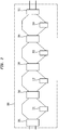
- Fig. 2 shows an example of such a variable encoder.
- encoder 300 includes a cascade of switches 301, 302, 303, and 304 and Walsh coders 311, 312, 313, and 314.
- Each switch is a 2x2 optical crossbar switch that routes or directs a signal into one or more of the Walsh coders to encode a signal with a particular Hadamard code.
- Switch 301 can be set so that an incoming signal can bypass Walsh coder 311 or pass through Walsh coder 311.
- Switch 302 can be set so that an incoming signal can bypass Walsh coder 312 or pass through Walsh coder 312.
- Switch 303 can be set so that an incoming signal can bypass Walsh coder 313 or pass through Walsh coder 313.
- Switch 304 can be set so that an incoming signal can bypass Walsh coder 314 or pass through Walsh coder 314.
- switches 301, 302, 303, and 304 are used to direct the signal to either bypass their respective Walsh coders or to pass through their respective Walsh coders thereby applying a Hadamard code to the signal.
- the encoder 300 if Fig. 2 could simplify the task of using bit-by-bit code state changes to perform data modulation (code-shift keying).
- the spectral phase encoder 300 generally works under the principle that Hadamard codes of order N, H n , where n ⁇ 1...N, can be decomposed into products of a smaller basis set of Walsh codes W m of length N where the maximum number of Walsh codes required to reconstruct any of these N Hadamard code is log 2 (N).
- the Walsh codes like the Hadamard codes, are of length N and all the elements are either +1 or -1.
- the n th code W n of length N is characterized by alternating blocks of +1's and -1's where the length of the blocks is given by n.
- the Walsh codes are as discussed below.
- W 8 consisting of eight +1's followed by eight - 1's (+ + + + + + + + + + + + + + + + + + + + + + + + + + + + + + + + + + + + + + + + + + + + + + + + + + + + + + + + + + + + + + + + + + + + + + + + + + + + + + + + + + + + + + + + + + + + + + + + + + + + + + + + + + + + + + + + + + + + + + + + + + + + + + + + + + + + + + + + + + + + + + + + + + + + + + + + + + + + + + + + + + + + + + + + + + + + + + + + + + + + + + + + + + + + + + + + + + + + + + + + + + + + + + + + + + + + + + + + + + + + + + + + + + + + + + + + + + + +
- W 4 consisting of two sets of four +1's and four - 1's. (+ + + + + - - - - + + + + + + - - - -).
- W 2 consisting of four sets of two +1's and two - 1's. (+ + - - + + - - + + - - + + - - -).
- W 1 consisting of eight sets of +1's and -1's. (+ - + - + - + - + - + - + - + -).
- any of the 16 codes available in H 16 can be expressed as a product of W 1 , W 2 , W 4 , and W 8 (which may correspond to Walsh coders 314, 313, 312, and 311 respectively).
- the sum of the Walsh indices equals one less than the corresponding Hadamard code index.
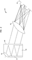
- Fig. 3 shows an example of a Walsh coder 400 in accordance with an aspect of the invention.
- an optical signal enters a collimated lens 401.
- the optical signal passes through space 403 toward a gradient reflective coating 404.
- Space 403 may be an air gap or it may be filled with a glass substrate.
- Gradient reflective coating 404 may be a metallic coating such as silver or aluminum which is highly-reflective/low-transmissive near the collimating lens (where the light is bright) and tapers off to low-reflectance/high-transmitance further from the lens. The intention is that each bounce should transmit an equal amount of light.
- the coating allows a portion of the optical signal to pass through and reflects the other portion through space 403 toward a 100% reflective material.
- the portion(s) of the optical signal that pass through coating 404 are directed toward a Fourier lens 405.
- Fourier lens 405 converts the incoming signal into the frequency domain and directs the converted signal onto a reflective phase mask 406 as shown in Fig. 3 .
- Reflective phase mask 406 corresponds to the respective Walsh code.
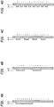
- Reflective phase mask is different for each Walsh coder. For instance, as shown in Fig. 4A , for Walsh coder W 8 , the phase mask would be set at a height ⁇ /2 for 8 bits and then changed back to the base level. As shown in Fig. 4B , for Walsh coder W 4 , the phase mask would be set at height ⁇ /2 for 4 bits and then changed back to the base level for 4 bits. This pattern is then repeated one more time. As shown in Fig. 4C , for Walsh coder W 2 , the phase mask would be set at height ⁇ /2 for 2 bits and then changed back to the base level for 2 bits. This pattern is then repeated three more times. As shown in Fig. 4D , for Walsh coder W 1 , the phase mask would alternate in between height ⁇ /2 and the base height for a total length of 16 bits.
- any given Walsh function can be implemented by phase coders of the type contemplated for standard Hadamard codes and the successive products of the Walsh codes correspond to passing through the corresponding Walsh coders in cascade (in any order).
- Fig. 2 shows Walsh coders W8, W4, W2, and W1 (311, 312, 313, and 314 respectively) in that particular order, that order may be changed to any combination such as W8, W1, W4, and W2 for example.
- the switches route the signal through the following stage in the Walsh cascade or cause the signal to bypass that stage.
- element 305 may be a passive coupler (which introduces an additional 3 dB loss) or an additional crossbar switch which may reduce the signal loss by connecting the output port to the active branch of the previous state; in short, the state of the rightmost switch (element 305) would match the state of the switch 304.
- the different paths through the spectral phase encoder 300 may, for different Hadamard codes, cause the signals to incur different losses and different levels of bin edge filtering effects.
- encoder 300 may include mediation measures such as in-line amplifiers at each stage, lumped losses in the bypass legs or a single gain-clamped amplifier to compensate for the loss variations.
- the cascade depth might be reduced. For example, if the variable coder need only provide access to odd-numbered Hadamard codes, the W 1 stage of the cascade could be eliminated. If the variable coder need only provide access to even-numbered Hadamard codes, the W 1 stage of the cascade need not be switched. If the variable coder need only provide access to Hadamard codes for n ⁇ 9, the W 8 stage of the cascade could be eliminated.
- this approach is not limited to the standard real-valued (+1, -1) codes.
- G N There exists at least one variety of complex generalizations of the Hadamard code that can be implemented via augmenting the cascade.
- a spectral phase decoder 500 illustrated in Fig. 5 .
- An incoming encoded data stream 135 from network 140 is applied to the spectral phase decoder 500.
- the spectral phase decoder 500 or 144 applies the phase conjugate of the coders applied in the spectral phase encoder 300 or 132.
- the spectral phase encoder may also be used as a spectral phase decoder when using Walsh-Hadamard codes.
- the spectral phase decoder 500 may reproduce the phase conjugate of all of the N Hadamard codes in order to decode the encoded data stream.
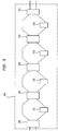
- Fig. 5 shows an example of such a decoder.
- decoder 500 includes a cascade of switches 501, 502, 503, and 504 and coders 511, 512, 513, and 514.
- Coders 511, 512, 513, and 514 of decoder 500 are phase conjugates of coders 311, 312, 313, and 314 in encoder 300.
- Each switch is a 2x2 optical crossbar switch that routes or directs a signal into one or more of the coders to encode a signal with a particular Hadamard code.
- Switch 501 can be set so that an incoming signal can bypass coder 511 or pass through coder 511.
- Switch 502 can be set so that an incoming signal can bypass coder 512 or pass through coder 512.
- Switch 503 can be set so that an incoming signal can bypass coder 513 or pass through coder 513.
- Switch 504 can be set so that an incoming signal can bypass coder 514 or pass through coder 514.
- switches 501, 502, 503, and 504 are used to direct the signal to either bypass their respective coders or to pass through their respective coders thereby decoding the signal.
- element 505 may be a passive coupler (which introduces an additional 3 dB loss) or an additional crossbar switch which may reduce the signal loss by connecting the output port to the active branch of the previous state; in short, the state of the rightmost switch (element 505) would match the state of the switch 504.
- optical switch technology promises to be faster than either MEMS-based, liquid-crystal-based, or thermal phase adjustments and could make this approach suitable for situations in which the code must be changed on a rapid timescale.
Landscapes
- Engineering & Computer Science (AREA)
- Computer Networks & Wireless Communication (AREA)
- Signal Processing (AREA)
- Optical Communication System (AREA)
Claims (14)
- Variabler Spektralphasencodierer (300), der Folgendes umfasst:mehrere Schalter, die wenigstens einen ersten Schalter (301) und einen zweiten Schalter (302) umfassen; undwenigstens einen Codierer (311), der zwischen den ersten Schalter (301) und den zweiten Schalter (302) der mehreren Schalter gekoppelt ist, wobei der erste Schalter (301) einen ersten Zustand aufweist, der bewirkt, dass ein optisches Signal, das in den ersten Schalter eingegeben wird, zu dem zweiten Schalter durchgeleitet wird, indem der Codierer (311) umgangen wird, und einen zweiten Zustand, der bewirkt, dass ein optisches Signal, das in den ersten Schalter eingegeben wird, durch den Codier (311) hindurchgeleitet wird, bevor es durch den zweiten Schalter hindurchgeleitet wird, wobei der erste Schalter dazu funktionsfähig ist, das optische Signal selektiv entlang eines Pfades durch den Codierer (311) hindurch oder diesen umgehend zu leiten, um eine Hadamard-Sequenz auf das optische Signal anzuwenden.
- Spektralphasencodierer nach Anspruch 1, wobei jeder Schalter (301, 302) unter den mehreren Schaltern ein 2×2-Kreuzschienenschalter ist.
- Spektralphasencodierer nach Anspruch 1, der ferner einen dritten Schalter (303) und einen vierten Schalter (304) umfasst.
- Spektralphasencodierer nach Anspruch 3, der ferner Folgendes umfasst:wenigstens einen Codierer (312), der zwischen den zweiten Schalter und den dritten Schalter gekoppelt ist;wenigstens einen Codierer (313), der zwischen den dritten Schalter und den vierten Schalter gekoppelt ist; undwenigstens einen Codierer (314), der nach dem vierten Schalter gekoppelt ist.
- Spektralphasencodierer nach Anspruch 4, wobei jeder des ersten, zweiten, dritten und vierten Schalters dazu funktionsfähig ist, das optische Signal selektiv durch eine Kombination der Codierer (311, 312, 313, 314) zu leiten, um eine Hadamard-Sequenz auf das optische Signal anzuwenden.
- Spektralphasencodierer nach Anspruch 1, der ferner einen zusätzlichen 2×2-Kreuzschienenschalter (305) umfasst.
- Spektralphasencodierer nach Anspruch 1, der ferner einen passiven Koppler umfasst.
- Spektralphasendecodierer (500), der Folgendes umfasst:mehrere Schalter, die einen ersten Schalter (501) und einen zweiten Schalter (502) umfassen; undwenigstens einen Decodierer (511), der zwischen den ersten Schalter (501) und den zweiten Schalter (502) der mehreren Schalter gekoppelt ist, wobei der erste Schalter (501) einen ersten Zustand aufweist, der bewirkt, dass ein optisches Signal, das in den ersten Schalter eingegeben wird, zu dem zweiten Schalter hindurchgeleitet wird, indem der Decodierer (511) umgangen wird, und einen zweiten Zustand, der bewirkt, dass ein optisches Signal, das in den ersten Schalter eingegeben wird, durch den Decodierer (511) hindurchgeleitet wird, bevor es zu dem zweiten Schalter hindurchgeleitet wird, wobei der erste Schalter (501) dazu funktionsfähig ist, das optische Signal entlang eines Pfades durch den Decodierer oder diesen umgehend zu leiten, um das optische Signal zu decodieren.
- Spektralphasendecodierer nach Anspruch 8, wobei jeder Schalter unter den mehreren Schaltern (501, 502) ein 2×2-Kreuzschienenschalter ist.
- Spektralphasendecodierer nach Anspruch 8, der ferner einen dritten Schalter (503) und einen vierten Schalter (504) umfasst.
- Spektralphasendecodierer nach Anspruch 8, der ferner Folgendes umfasst:wenigstens einen Decodierer (512), der zwischen den zweiten Schalter und den dritten Schalter gekoppelt ist;wenigstens einen Decodierer (513), der zwischen den dritten Schalter und den vierten Schalter gekoppelt ist; undwenigstens einen Decodierer (514), der nach dem vierten Schalter gekoppelt ist.
- Spektralphasendecodierer nach Anspruch 11, wobei jeder des ersten, zweiten, dritten und vierten Schalters dazu funktionsfähig ist, das optische Signal selektiv durch eine Kombination der Decodierer zu leiten, um ein Hadamard-codiertes optisches Signal zu decodieren.
- Spektralphasendecodierer nach Anspruch 8, der ferner einen zusätzlichen 2×2-Kreuzschienenschalter (505) umfasst.
- Spektralphasendecodierer nach Anspruch 8, der ferner einen passiven Koppler (505) umfasst.
Applications Claiming Priority (2)
| Application Number | Priority Date | Filing Date | Title |
|---|---|---|---|
| US11/429,686 US7646980B1 (en) | 2006-05-08 | 2006-05-08 | Variable spectral phase encoder/decoder based on decomposition of Hadamard codes |
| PCT/US2007/010948 WO2008054524A2 (en) | 2006-05-08 | 2007-05-04 | Variable spectral phase encoder/decoder based on decomposition of hadamard codes |
Publications (3)
| Publication Number | Publication Date |
|---|---|
| EP2018727A2 EP2018727A2 (de) | 2009-01-28 |
| EP2018727A4 EP2018727A4 (de) | 2011-08-17 |
| EP2018727B1 true EP2018727B1 (de) | 2018-02-07 |
Family
ID=39344807
Family Applications (1)
| Application Number | Title | Priority Date | Filing Date |
|---|---|---|---|
| EP07867101.3A Active EP2018727B1 (de) | 2006-05-08 | 2007-05-04 | Kodier- und dekodiergerät mit variablen spektralphasen auf grundlage der zersetzung von hadamard-codes |
Country Status (4)
| Country | Link |
|---|---|
| US (2) | US7646980B1 (de) |
| EP (1) | EP2018727B1 (de) |
| CA (1) | CA2651497C (de) |
| WO (1) | WO2008054524A2 (de) |
Families Citing this family (7)
| Publication number | Priority date | Publication date | Assignee | Title |
|---|---|---|---|---|
| US7646980B1 (en) * | 2006-05-08 | 2010-01-12 | Telcordia Technologies, Inc. | Variable spectral phase encoder/decoder based on decomposition of Hadamard codes |
| US7831049B1 (en) * | 2006-05-10 | 2010-11-09 | Nucrypt, LLC | Enhanced encryption method and system for ultra secure applications |
| US7778547B2 (en) * | 2006-06-01 | 2010-08-17 | Telcordia Technologies, Inc. | Code grouping for optical networks |
| US8406423B2 (en) * | 2010-03-16 | 2013-03-26 | Telcordia Technologies, Inc. | Multi-bit cryptographically secure encryptor for M-ary spectral phase encoder optical code division multiple access |
| US10693562B2 (en) * | 2016-10-18 | 2020-06-23 | Nippon Telegraph And Telephone Corporation | Encoding device and decoding device |
| US9735911B1 (en) * | 2016-12-26 | 2017-08-15 | Manouher Naraghi | System and apparatus for multi user communication over a single fiber |
| CN115664532B (zh) * | 2022-09-20 | 2024-08-16 | 苏州大学 | 基于正交时空码分多址的多芯光纤串扰抑制方法和设备 |
Family Cites Families (4)
| Publication number | Priority date | Publication date | Assignee | Title |
|---|---|---|---|---|
| US6025944A (en) * | 1997-03-27 | 2000-02-15 | Mendez R&D Associates | Wavelength division multiplexing/code division multiple access hybrid |
| US6236483B1 (en) * | 1998-07-30 | 2001-05-22 | Codestream Technologies Corporation | Optical CDMA system using sub-band coding |
| US7646980B1 (en) * | 2006-05-08 | 2010-01-12 | Telcordia Technologies, Inc. | Variable spectral phase encoder/decoder based on decomposition of Hadamard codes |
| US7778547B2 (en) * | 2006-06-01 | 2010-08-17 | Telcordia Technologies, Inc. | Code grouping for optical networks |
-
2006
- 2006-05-08 US US11/429,686 patent/US7646980B1/en active Active
-
2007
- 2007-05-04 EP EP07867101.3A patent/EP2018727B1/de active Active
- 2007-05-04 CA CA2651497A patent/CA2651497C/en active Active
- 2007-05-04 WO PCT/US2007/010948 patent/WO2008054524A2/en not_active Ceased
-
2009
- 2009-11-23 US US12/623,728 patent/US8699883B2/en active Active
Non-Patent Citations (1)
| Title |
|---|
| None * |
Also Published As
| Publication number | Publication date |
|---|---|
| WO2008054524A2 (en) | 2008-05-08 |
| WO2008054524A3 (en) | 2008-09-12 |
| CA2651497C (en) | 2014-07-08 |
| US20100067922A1 (en) | 2010-03-18 |
| US7646980B1 (en) | 2010-01-12 |
| US20100003031A1 (en) | 2010-01-07 |
| EP2018727A2 (de) | 2009-01-28 |
| US8699883B2 (en) | 2014-04-15 |
| EP2018727A4 (de) | 2011-08-17 |
| CA2651497A1 (en) | 2008-05-08 |
Similar Documents
| Publication | Publication Date | Title |
|---|---|---|
| EP2030353B1 (de) | Kodegruppierung für optische netzwerke | |
| US20100183309A1 (en) | System and Method for OCDM-Based Photonic Layer Security Robustness to Archival Attack | |
| US8699883B2 (en) | Variable spectral phase encoder/decoder based on decomposition of hadamard codes | |
| US20100221009A1 (en) | Phase Chip Frequency-Bins Optical Code Division Multiple Access | |
| US7620328B2 (en) | Multi-wavelength optical CDMA with differential encoding and bipolar differential detection | |
| CA2524819C (en) | Spectrally phase encoded optical code division multiple access system | |
| CA2376858C (en) | Communication systems and apparatus with synchronous orthogonal coding | |
| US6778102B1 (en) | Communication system and apparatus with synchronous orthogonal coding | |
| US20080107430A1 (en) | Mixed phase and wavelength coded optical code division multiple access system | |
| EP1889381B1 (de) | Optische codegeroutete netzwerke | |
| CA2725804C (en) | System and method for ocdma-based photonic layer security robustness to archival attack | |
| Huang et al. | Signal Processing Techniques for Data Confidentiality in OCDMA Access Networks | |
| JPH104396A (ja) | 光符号変換方式とクロスコネクト方式及び装置 |
Legal Events
| Date | Code | Title | Description |
|---|---|---|---|
| PUAI | Public reference made under article 153(3) epc to a published international application that has entered the european phase |
Free format text: ORIGINAL CODE: 0009012 |
|
| 17P | Request for examination filed |
Effective date: 20081107 |
|
| AK | Designated contracting states |
Kind code of ref document: A2 Designated state(s): AT BE BG CH CY CZ DE DK EE ES FI FR GB GR HU IE IS IT LI LT LU LV MC MT NL PL PT RO SE SI SK TR |
|
| AX | Request for extension of the european patent |
Extension state: AL BA HR MK RS |
|
| RBV | Designated contracting states (corrected) |
Designated state(s): DE GB |
|
| DAX | Request for extension of the european patent (deleted) | ||
| RBV | Designated contracting states (corrected) |
Designated state(s): DE GB |
|
| A4 | Supplementary search report drawn up and despatched |
Effective date: 20110720 |
|
| RIC1 | Information provided on ipc code assigned before grant |
Ipc: H04B 10/04 20060101ALI20110714BHEP Ipc: H04B 10/12 20060101ALI20110714BHEP Ipc: H04J 14/00 20060101AFI20110714BHEP Ipc: G02F 1/01 20060101ALI20110714BHEP Ipc: H04J 14/02 20060101ALI20110714BHEP |
|
| 17Q | First examination report despatched |
Effective date: 20110729 |
|
| RAP1 | Party data changed (applicant data changed or rights of an application transferred) |
Owner name: TTI INVENTIONS E LLC |
|
| GRAP | Despatch of communication of intention to grant a patent |
Free format text: ORIGINAL CODE: EPIDOSNIGR1 |
|
| STAA | Information on the status of an ep patent application or granted ep patent |
Free format text: STATUS: GRANT OF PATENT IS INTENDED |
|
| RIC1 | Information provided on ipc code assigned before grant |
Ipc: H04J 14/00 20060101AFI20170719BHEP |
|
| INTG | Intention to grant announced |
Effective date: 20170816 |
|
| GRAS | Grant fee paid |
Free format text: ORIGINAL CODE: EPIDOSNIGR3 |
|
| GRAA | (expected) grant |
Free format text: ORIGINAL CODE: 0009210 |
|
| STAA | Information on the status of an ep patent application or granted ep patent |
Free format text: STATUS: THE PATENT HAS BEEN GRANTED |
|
| RAP1 | Party data changed (applicant data changed or rights of an application transferred) |
Owner name: NYTELL SOFTWARE LLC |
|
| AK | Designated contracting states |
Kind code of ref document: B1 Designated state(s): DE GB |
|
| REG | Reference to a national code |
Ref country code: GB Ref legal event code: FG4D |
|
| REG | Reference to a national code |
Ref country code: DE Ref legal event code: R096 Ref document number: 602007053899 Country of ref document: DE |
|
| REG | Reference to a national code |
Ref country code: DE Ref legal event code: R097 Ref document number: 602007053899 Country of ref document: DE |
|
| PLBE | No opposition filed within time limit |
Free format text: ORIGINAL CODE: 0009261 |
|
| STAA | Information on the status of an ep patent application or granted ep patent |
Free format text: STATUS: NO OPPOSITION FILED WITHIN TIME LIMIT |
|
| 26N | No opposition filed |
Effective date: 20181108 |
|
| P01 | Opt-out of the competence of the unified patent court (upc) registered |
Effective date: 20230527 |
|
| PGFP | Annual fee paid to national office [announced via postgrant information from national office to epo] |
Ref country code: DE Payment date: 20250409 Year of fee payment: 19 |
|
| PGFP | Annual fee paid to national office [announced via postgrant information from national office to epo] |
Ref country code: GB Payment date: 20260320 Year of fee payment: 20 |