EP2018463B1 - Ablenkkeil - Google Patents
Ablenkkeil Download PDFInfo
- Publication number
- EP2018463B1 EP2018463B1 EP07732812A EP07732812A EP2018463B1 EP 2018463 B1 EP2018463 B1 EP 2018463B1 EP 07732812 A EP07732812 A EP 07732812A EP 07732812 A EP07732812 A EP 07732812A EP 2018463 B1 EP2018463 B1 EP 2018463B1
- Authority
- EP
- European Patent Office
- Prior art keywords
- whipstock
- deflection
- face surface
- mill
- face
- Prior art date
- Legal status (The legal status is an assumption and is not a legal conclusion. Google has not performed a legal analysis and makes no representation as to the accuracy of the status listed.)
- Active
Links
Images


Classifications
-
- E—FIXED CONSTRUCTIONS
- E21—EARTH DRILLING; MINING
- E21B—EARTH DRILLING, e.g. DEEP DRILLING; OBTAINING OIL, GAS, WATER, SOLUBLE OR MELTABLE MATERIALS OR A SLURRY OF MINERALS FROM WELLS
- E21B7/00—Special methods or apparatus for drilling
- E21B7/04—Directional drilling
- E21B7/06—Deflecting the direction of boreholes
- E21B7/061—Deflecting the direction of boreholes the tool shaft advancing relative to a guide, e.g. a curved tube or a whipstock
-
- E—FIXED CONSTRUCTIONS
- E21—EARTH DRILLING; MINING
- E21B—EARTH DRILLING, e.g. DEEP DRILLING; OBTAINING OIL, GAS, WATER, SOLUBLE OR MELTABLE MATERIALS OR A SLURRY OF MINERALS FROM WELLS
- E21B7/00—Special methods or apparatus for drilling
- E21B7/04—Directional drilling
- E21B7/06—Deflecting the direction of boreholes
-
- E—FIXED CONSTRUCTIONS
- E21—EARTH DRILLING; MINING
- E21B—EARTH DRILLING, e.g. DEEP DRILLING; OBTAINING OIL, GAS, WATER, SOLUBLE OR MELTABLE MATERIALS OR A SLURRY OF MINERALS FROM WELLS
- E21B29/00—Cutting or destroying pipes, packers, plugs, or wire lines, located in boreholes or wells, e.g. cutting of damaged pipes, of windows; Deforming of pipes in boreholes or wells; Reconditioning of well casings while in the ground
- E21B29/06—Cutting windows, e.g. directional window cutters for whipstock operations
-
- E—FIXED CONSTRUCTIONS
- E21—EARTH DRILLING; MINING
- E21B—EARTH DRILLING, e.g. DEEP DRILLING; OBTAINING OIL, GAS, WATER, SOLUBLE OR MELTABLE MATERIALS OR A SLURRY OF MINERALS FROM WELLS
- E21B7/00—Special methods or apparatus for drilling
- E21B7/04—Directional drilling
- E21B7/06—Deflecting the direction of boreholes
- E21B7/064—Deflecting the direction of boreholes specially adapted drill bits therefor
Definitions
- THIS INVENTION relates to a whipstock and to an associated single trip whipstock system, and more particularly to a system that can be run into the well bore as an assembly and oriented, set and operated to mill a window in the casing of the well bore to enable a sidetrack or lateral in the surrounding formation in a single trip.
- the system may also be used complimentary to a multi lateral operation and completion of the well bore thereof.
- branches In the drilling of oil wells it is sometimes necessary to form a branch extending off an existing bore, maintaining where possible as much of the original integrity of the casing for completion tieback purposes.
- These branches are known as laterals or sidetracks dependent upon the future application of the exit and whether communication is required with the original bore (mother bore).
- These branches are generally formed through insertion of a tapered deflecting device - whipstock - into the existing bore, which is used to deflect a milling tool or assembly radially outward from the well bore axis.
- the milling assembly traverses the length of the whipstock making a cut into the casing in the well bore at the top of the whipstock, and elongating it as it travels along the whipstock face.
- the milling assembly As the milling assembly reaches the lower end of the whipstock, it becomes more exposed to the formation until it departs the original well bore milling or drilling into the surrounding formation.
- the milling assembly can reasonably be expected to drill a short length of formation, or an extended length subject to the dressing and dressing characteristics applied to the milling tools. Once this formation has been drilled the milling assembly is recovered from the well bore in readiness for drilling applications.
- anchoring means which may include an isolation method such as a packer, or packer element combined with the anchor, which can be run in conjunction with the whipstock and milling assembly in the hole, and which prevent relative movement between the whipstock and the anchor or packer.
- anchors can also be mechanically or hydraulically set in the well bore, and may be set in conjunction with other barriers which have been preset in the well bore prior to running the whipstock assembly.
- an anchor mechanically - having first set the barrier for example a bridge plug
- this additional barrier is run or not, and the whipstock system set hydraulically, the main features of the whipstock system remain the same, however, in the hydraulic set option, there is usually a means to circulate for orientation purposes with a MWD tool (Measurement While Drilling tool) to the well bore without setting the anchor.
- MWD tool Measurement While Drilling tool
- a bypass valve or ported sub is required, to allow fluid bypass through the drill string.
- Actuation of the valve is usually determined by flow rate and subsequent pressure drop through a piston, or piston and nozzle combination, which is used to shear pins or cycle the piston in response to switching the flow on and off till the valve closes, allowing a static pressure to build up in the system to set the anchor in the well bore.
- a ported sub is used, and this can be in conjunction with a valve, the flow rate is increased dynamically until the pressure drop across the port circulating flow to annulus is high enough to initiate the setting sequence in the anchor. Either way, and with whatever valve means, utilising MWD, and a bypass means, the orientation of the whipstock system can be determined such that it can be adjusted prior to initiating the setting sequence.
- the present invention claims to improve the known techniques and methods for creating the window to enable a lateral or sidetrack to be drilled.
- the milling tool is secured at the top of the whipstock by a releasable fastening means such as a shear bolt.
- a releasable fastening means such as a shear bolt.
- the upper end of the whipstock is formed with a tapering angle which may vary according to the requirement for a shallow or steep departure angle from the existing well bore - normally defined as the dog leg severity (DLS) across the whipstock in degrees per hundred feet (°/100ft (30.5m)).
- DLS dog leg severity
- a low DLS requires that the whipstock face angle may be anywhere between 0.5° and 3°, but not limited to this range, and a high DLS require that the whipstock face angle is between 3° and 10°, but not limited to this range.
- the top of the whipstock is plain and consistent with the face angle above
- the whipstock will be provided with a kick out lug, which allows interaction with and support of the milling assembly, as well as allowing the use of a full gauge mill, and prevents inadvertent milling away of the top of the whipstock.
- the kick out lug can comprise one ramp, and preferably is provided with at least two ramps so that as the milling assembly mills and wears the kick out lug profile away, the remaining critical bearing area, that is ineffective as described below, is replaced with at least a second bearing face to support the milling assembly, and preserve the whipstock face.
- the kick out lug is fully sacrificial in this respect, and is not fully consumed until the first mill has fully cut through the casing and can then traverse the whipstock face in the normal manner without necessitating a change in the milling assembly.
- the kick out lug surface is fully compliant with the mill profile and both are described in more detail below.
- the whipstock top may be profiled to interact with the milling assembly to assist in the radial movement as the mill engages and traverses the whipstock, with resultant wear problems as shown in GB 2348660B which sought to reduce problems as a consequence of the system shown in US 5,771,972 .
- the solution provided by GB 2348660B does not entirely eliminate the wear problems, and subject to milling assembly design and its interaction with the casing and formation, may still result in wear problems, and significantly, both systems above are dependent upon the interaction with the whipstock top directly with the first mill, and when the bearing area of the whipstock top reduces, the whipstock mills away preferentially although this is not desirable.
- US 5,109,924 US 5,445,222 , US 6,102,123 , EP 1,222,357 B1 , GB 2310231 A , and US 4,397,355 A1 .
- US 5,826,651 portrays similar milling assemblies which have detachable nose cones or faces which are consumed down hole by milling or explosive means as part of the window milling and exiting process, or left in pockets in the whipstock face to facilitate window milling in one run.
- US patent No. 5, 894, 889 discloses a side tracking system including a window mill having a full diameter cutting surface and a reduced diameter tapered cutting surface, and a whipstock having a ramp engaging the reduced diameter cutting surface.
- the materials of the whipstock have a first cutability and the materials of the casing have a second cutability.
- the reduced diameter cutting surface contacts the whipstock ramp at a first contact area and fill diameter cutting surface contacts the wall of the casing at a second contact area.
- a cutability ratio is the first cutability divided by the second cutability
- a contact stress ratio is the first contact stress divided by the second contact stress.
- the mill cuts the casing rather than the whipstock by maintaining the product of the cutability ratio and the contact stress ratio less than one.
- the height of the reduced diameter cutting surface is greater than the height of the full diameter cutting surface.
- the ramp includes a plurality of surfaces having different angles whereby the rate of deflection of the mill by the whipstock varies as the mill is lowered into the borehole.
- the ramp of the whipstock includes two surfaces having steep angles, one steep angled surface causing the mill to punch through the wall of the casing and the second steep angled surface moving the centre of the mill across the wall of the casing.
- GB24203595 discloses a side tracking system having a pair of serially connected mills, each having a plurality of circumferentially arranged blades having a tapered cutting portion thereon for cutting a window in the casing and then sidetracking in a formation.
- a whipstock has at least three axially spaced ramps, each ramp being interspaced by a substantially axially extending portion.
- Each of the ramps have the same angle of inclination to a longitudinal axis and the distance between the ramps is the same as the distance between the tapered portions on the mills so that, in operation, load is shared between both mills.
- the mills have a button of hardened material located on the tapered cutting portions so that the button abrades the whipstock ramps.
- a whipstock having a longitudinal axis and comprising: a tapered face surface, at least part of which is inclined with respect to the longitudinal axis, for guiding a milling head as the milling head passes from a top end to a bottom end of the face surface; and a deflection arrangement having first and second deflection surfaces, each of the first and second deflection surfaces being inclined at a greater angle with respect to the longitudinal axis than the face surface in the region of the deflection arrangement, wherein the first deflection surface is located closer to the top end of the face surface than the second deflection surface, characterised in that the deflection arrangement protrudes from the face surface and at least a part of each of the deflection surfaces is raised above the face surface.
- the deflection arrangement is joined to the face surface.
- the deflection arrangement is integral with the face surface.
- first and second deflection surfaces are substantially parallel with each other, with the planes of the surfaces being offset from one another.
- each of the deflection surfaces has a top edge, being the edge nearest to the top end of the face surface, and a bottom edge, being the edge nearest to the bottom end of the face surface, and wherein the bottom edge of the first deflection surface is raised above the face surface by a greater amount than the top edge of the second deflection surface.
- the second deflection surface is provided substantially adjacent the first deflection surface.
- a space is provided between the first and second deflection surfaces.
- the deflection arrangement is provided as a single unit protruding from the face surface.
- the deflection arrangement is provided at or close to the top end of the face surface.
- At least the first and second deflection surfaces are formed from a material which is harder than that from which the face surface is formed.
- the whipstock comprises at least a third deflection surface, wherein: at least a part of the third deflection surface is raised above the face surface; the third deflection surface is inclined at a greater angle with respect to the longitudinal axis than the face surface in the region of the deflection arrangement; and the third deflection surface is located further from the top end of the face surface than the second deflection surface.
- the whipstock comprises at least a fourth deflection surface, wherein: at least a part of the fourth deflection surface is raised above the face surface; the fourth deflection surface is inclined at a greater angle with respect to the longitudinal axis than the face surface in the region of the deflection arrangement; and the fourth deflection surface is located further from the top end of the face surface than the third deflection surface.
- a whipstock assembly comprising: a whipstock according to any of the above; and a milling arrangement comprising a milling head, at least a part of the profile of the milling head being shaped so that, when the milling head is guided by the face surface of the whipstock during normal use thereof, the part of the profile is substantially parallel with the at least one of the deflection surfaces when the part of the profile meets the at least one of the deflection surfaces.
- the part of the profile is substantially parallel with the first deflection surface when the part of the profile meets the first deflection surface and is substantially parallel with the second deflection surface when the part of the profile meets the second deflection surface.
- Another aspect of the present invention provides a method of guiding a milling head to form a cutout in the casing of a bore, comprising the steps of: providing a whipstock having a longitudinal axis and comprising: a tapered face surface, at least part of which is inclined with respect to the longitudinal axis, for guiding a milling head as the milling head passes from a top end to a bottom end of the face surface; and a deflection arrangement having first and second deflection surfaces, each of which is inclined at a greater angle with respect to the longitudinal axis than the face surface in the region of the deflection arrangement, wherein the first deflection surface is located closer to the top end of the face surface than the second deflection surface; locating the whipstock in the existing bore so that the top end thereof is uppermost; providing a milling arrangement comprising a milling head, at least a part of the profile of the milling head being shaped so that, when the milling head is guided by the face surface of the whipstock during normal use thereof,
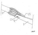
- the illustrated single trip whipstock assembly comprises a hinge connector 33; attached to a whipstock 1; a whipstock kick out lug 4; a securing means 3; a milling assembly 2 comprising a first mill 7; a second mill 8; whereby the milling assembly 2 is secured to the whipstock kick out lug 4 by a releasable connector 3.
- the whipstock 1 is connected to a hinge connector 33 by means of a hinge pin 31.
- the hinge connector 33 is attached to an anchor or packer by means of a threaded connection 43, and the milling assemblies are also attached to each other by means of a threaded connection 44.
- a hydraulic flow path is provided from the milling assembly to the hinge connector by means of pipes 15, 27, 29 and bores 16,32 to enable setting of a hydraulically activated packer or anchor assembly.
- the kick out lug 4 and releasable connector 3 are described in more detail hereinafter.
- the complete assembly is run in to the well on suitable pipe to the required depth, is correctly oriented, using either a UBHO sub or MWD tool located above a bypass valve, and the packer is set.
- a hydraulic fluid barrier is provided as an isolation means between the well bore fluid and the setting fluid for the anchor or packer.
- the connection 3 between the mill assembly 2 and the whipstock top 6 via the kick out lug 4 through slot 11, Figures 2 and 3 is released to allow the milling of a window in the surrounding casing, to enable the commencement of a rat hole using the first mill 7 for subsequent drilling operations to extend the lateral bore or sidetrack as required.
- the window which is initiated by the first mill 7 is extended by the second mill 8 and any other mill (not shown) included in the assembly, which is shown in Figure 10 .
- the first mill 2 is connected to the top of the whipstock 6 by means of at least one kick out lug 4 and at least one releasable fastener 3, for example a shear bolt as shown in Figure 2 whereby the mill is aligned with the kick out lug 4 via a locating hole 57, Figures 2 , 4a , 10 , on the mill 7 in the tapered profile 19, Figure 10 and 11 at the extreme top of the whipstock 6.
- the kick out lug 4 is positioned at the top of the whipstock 6, the specific location being determined by a measured offset distance from the top of the whipstock subject to mill diameter and casing bore to ensure the assembly can pass through the bore of the casing and mill through the wall of the casing accordingly.
- the location can be predetermined by aligning hole 9 in the top of the whipstock with any of the holes 10 in the kick out lug 4 Figure 2 , and Figure 3 , which provides axial displacement at the top of the whipstock 6, as described.
- the alignment holes may be through the back of the whipstock and blind in the kick out lug as shown, or drilled completely through the kick out lug. Alignment may be by use of a suitable dowel or other appropriate guide means.
- the kick out lug may be secured to the top of the whipstock by bolting, or welding, or braising, or even as an integral part of the whipstock.
- the shear bolt 3 is inserted through a slot 11 in the back of the whipstock and engages a bore in the kick out lug 4 and mill head 7 respectively, such that the shear bolt head is fully encompassed in the kick out lug, such that it will be totally consumed when the milling assembly traverses and mills off the kick out lug.
- the sheared section remaining in the mill head is retained by conventional means such as loctite, or a nylok insert 5. This secures the mill head 7 to the top of the whipstock 6 via the kick out lug 4.
- the location of the bore in the mill head is significant, as the mill head is provided with a taper 19 matching the kick out lug tapers, 46, 47 as shown in Figure 13 , and as shown in Figure 2 , and Figure 4 , is attached to the uppermost tapering face 46, Figure 12 .
- the slot 11, Figure 3 in the back of the whipstock allows for axial movement of the block without being constrained by a locating hole for the shear bolt 3.
- the mill 2 is now attached to the whipstock 1 and is used to convey the whipstock into the well bore casing.
- the shear bolt 22 attachment means may be located in a hole 57 in the mill head 7, for example by a thread, which is then inserted into the conical hole 56 in the top tapered face 46 of the kick out lug, and which may be secured by a long pin 23 inserted from the lower end of the kick out lug 4 as shown.
- the long pin 23, may be threaded at one end to secure it in the locating hole, ideally with a left hand thread, such that the milling action as the mill traverses the kick out lug in a clockwise (looking on the mill from above) direction, will not cause it to unscrew.
- the purpose being to consume all attachment means through milling, or to recover them to surface.
- This alternative locating means can allow the mill 2 movement relative to the top of the whipstock through use of a conical hole 56 and a parallel bolt extension 58, Figure 4a , with a domed face, and is therefore able to pivot within the well bore casing (not shown) to negotiate any deviation there through.
- torque may be transmitted by the milling assembly 2, through the bolt and kick out lug to the whipstock top 6.
- the first mill 7 is formed with a multiplicity of blades 55, which extend across the face of the mill in first a taper 19 before transitioning to an elliptical form and which extend along the side of the mill head body 7 shown in Figure 10 , and Figure 11 .
- the shear bolt location which is welded to or machined integral with the body of the mill head 7 is provided with a location hole 57, Figure 4 , whereby the strength of the section is sufficient to support the whipstock 1 and hinge connector 33 with anchor or packer (not shown), and to withstand an axial force in either direction (up or down relative to the whipstock top 6) to shear release the bolt 3 or 22, and to safely transport the assembly to the desired setting depth without premature release.
- the milling assembly 2, mill 7, 8, is full gauge and may remain so through the means of attachment to the whipstock 1 via the kick out lug 4.
- a shear bolt may be inserted transversely through the taper 19 of the mill head 7 and secured in the normal manner using loctite, nylock inserts, and even circlips or snap rings.
- the mill may be released from the top of the whipstock, and milling commenced. It will be noted, that the mill location at the top of the whipstock allows for a full gauge milling assembly, as the mill is not sandwiched between the whipstock top and the casing. This allows a mill and whipstock combination of maximum diameter if desired, to pass through the casing inside diameter.
- the anchor or packer is set in response to a fluid pressure generated in the system, for example at 1200psi (8.274mPa), when this pressure is reached, it can be increased to a pressure such as 2000psi (13.79mPa) or 3000psi (20.68mPa), and sometimes there may be even higher setting pressures as part of the system deployment.
- the mill 2 communicates hydraulically with the anchor or packer through a hydraulic path in the whipstock 1, via a hydraulic fitting 14, sealed in the mill head with seals 13 and nozzle 12, via a sacrificial hydraulic pipe 15, Figure 2 .
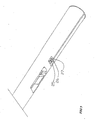
- This pipe is connected to another pipe 26 which is installed in a T slot 27, Figure 8 and Figure 9 , milled into the back of the whipstock 1, and is retained by virtue of the T slot shape, and connected to other pipe lengths 29 via connectors 25, 28, Figure 5 , 8 , 9 .
- Any other suitable means of forming this hydraulic communication is suitable, for example by gun drilling a hole along the length of the whipstock 1.
- the lower end of the whipstock is provided with a slot 42 to accommodate the movement of the hinge connector 33 with the express view to preventing the hose 29 from bulging out into contact with the casing when running the whipstock assembly in the hole.
- the hose is connected to the hinge connector tang 38, Figure 7 , by fitting 30, and to a bore 31 there through, Figure 5 .
- Connector 28 is a bulkhead type connector, and establishes a location for attaching pipe 26.
- the whipstock 1 is allowed to rotate a limited amount about the hinge pin 32, Figure 6 relative to the hinge connector 33 without fracturing the pipe 29, Figure 5 .
- This hinging capability can be isolated by suitable means if it is not desirable in any particular application.
- the anchor or packer, whipstock and milling assembly are filled with clean fluid up to and including the running tool, not shown, and the air bled out, before inserting the barrier.
- the assembly is then made up to the other necessary components to run in hole, such as flex joint, and bypass valve, followed by MWD (for example), and drill string to surface in the normal manner.
- this hydraulic arrangement is to provide a positive barrier, and then maximum circulation to and through the milling assembly for cooling of the cutting structure, as well as hole cleaning, whereby steel and formation cut by the mill is circulated to surface and out of the hole.
- the mill 2 is dressed with a wear resistant cutting structure, and the whipstock 1 is manufactured from a hardened material (alloy steel) in order to prevent or minimise any wear.
- the kick out lug 4 may be manufactured from a harder material than the whipstock, such that it protects the whipstock during the initial mill cut out operation through the casing, Figure 12 , Figure 13 , and Figure 14 . This can allow the whipstock to be manufactured from a conventional lower alloy and softer steel, reducing equipment costs, especially as the alloying elements are now significantly more expensive than in previous years.
- the kick out lug 4 is sacrificial, and is designed to support the mill head 7, pushing it radially outwards through the casing 45 in response to weight or downward force on the milling assembly 2, view C, Figure 12 .
- the milling is commenced.
- the mill 2 is rotated at the desired rotational speed, and lowered into contact with the top of the whipstock and kick out lug 4, view A, B and C.
- the kick out lug 4 may be of a single tapered design, as the mill progresses along it, the bearing area will reduce such that the mill is no longer supported, with the consequence that the mill may deflect into it and mill into the whipstock face during the critical phase of the cut out operation.
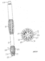
- the kick out lug 4 is provided with at least two tapered faces, 46, 47. As the mill is kicked out radially through reaction with taper 19, it will cut through the casing 45, and as the mill progresses, view D, Figure 12 , the spherical shape of the mill starts to consume the top of the lug, increasing the bearing area.
- the bearing area is reduced on the mating tapers, 19, 46, of the mill head 7 and kick out lug 4, whereby the support is provided entirely by the spherical face of the mill, however, because there may be a reaction from the formation resisting outward movement of the mill, the mill may have a tendency to fall back in toward the whipstock face. Furthermore, there is a reduction in bearing area from the tapered interacting faces. To combat this effect, the mill will pick up the second, lower tapered face 47 on the kick out lug 4, view E, and interact again with the taper 19 on the mill head, thus restoring the bearing area and support.
- the mill will progress along it making contact with the inner wall of the casing, and will effect an opening which will extend as the mill 2 traverses the length of the whipstock 1.
- the shape of the mill blades 55 are of an ellipse combined with a specific taper 19 in a spiral disposition when viewed from the end of the mill, Figure 10 .
- the taper 19 may vary to match the tapers 46, 47 provided on the kick out lug 4, and will be in the order of 8°-15°.
- the major diameter 18 of the ellipse on the blades 55 will act as a gauge and support the mill 2, minimising any wear to the whipstock 1 face 39.
- Additional mills are designed in a similar style to the mill 8, and perform the function of maintaining the window gauge and extending the top of the window up hole relative to the top of the whipstock 1 as required.
- the mill 2 may be smaller than full gauge, and mounted in a similar manner as described to the top of the whipstock, whereby the mounting means is a kick out lug 4 or block or similar protrusion, of sufficient height and location spacing to accommodate the mill 7, and fixing means 3 or 22.
- milling and whipstock assemblies may be utilised with mechanical or bottom set anchors, whereby the mill needs to be sheared down to ensure the anchor is set, furthermore, no hydraulic pipe work or barriers are necessary in this arrangement, such that circulation through the mill is immediately available.
- the mill 2 will circulate immediately through the hydraulic port 21, Figure 11 , and will be fitted with a protector sleeve or nozzle 12, to eliminate corrosion or circulation damage.
- the same orientation principles may be utilised, without the need for a bypass valve.
- the whipstock 1 is attached to the hinge connector 33 by means of a hinge pin 32 which is inserted through holes 41 in the bottom end of the whipstock 3, and hole located in the tang 38 in the top of the hinge connector 33, Figure 7 .
- the hinge pin 32 is retained by a retaining means such as a bolt 35 in three locations, such that in the event the whipstock 1 and anchor or packer need to be recovered from the well bore, they can be recovered by shearing the hinge pin 32 preferentially. This will result in the anchor or packer being left in the hole and will require recovery on a further run in the hole with an overshot or similar fishing tool.
- the recovery of the whipstock 1 may be achieved in at least two ways, though not limited to these examples.
- the retrieving hook may be provided with circulation ports, which can be used to wash any debris out of the hook slot 24 prior to engaging the hook.
- a die collar may be rotated over the top of the whipstock 1, on the taper 40 to engage the whipstock. Once engaged the whipstock may be released form the hinge connector and recovered to surface.
- Whipstocks are conventionally provided with a tapering face to guide the milling or drilling assembly out of the casing into the formation.
- DLS Dog Leg Severity
- Conventional whipstocks may have a face angle close to 3°, and some whipstocks have multiple face angles ranging from parallel to the well axis to 15°, subject to the application, with a view to varying the DLS across the whipstock face.
- the conventional 3° face angle is represented by the dashed line 50 on whipstock 49.
- Figure 15 shows an outwardly curved face 51, which gives the mill an accelerated attack path relative to the casing and formation, such that more formation will be removed in the proximity of the whipstock opening a larger hole adjacent the whipstock.
- Figure 16 shows an inwardly curved face 53, which gives the mill a lesser exposure to the formation, yet still allows removal of the casing (not shown) adjacent the whipstock top, thus preserving the mill. Comparing the relative window lengths, the outwardly curved face 51 will produce a shorter window profile and higher DLS, as evidenced by the run out 52 on the whipstock, whereas the inwardly curved face 53 will produce a longer window profile and lower DLS, as evidenced by the run out 54 on the whipstock.
- whipstocks in Figures15 and 16 will be utilised with the kick out lug 4 as provided on a conventionally angled whipstock.
- the whipstocks provide a guide face which can give a very short window, or conversely very long, within the constraints of the mechanical ability of the milling assembly to withstand the loads exerted during a high DLS exit (very short window), however, the curved profile generally avoids rapid changes in a radial direction across the whipstock face.
- Advantages for this type of whipstock profile may be derived by milling a window with a view to installing a device to seal the junction in the window opening, where formation will not obstruct the equipment that is deployed for this purpose. It is anticipated that it may be convenient to recover the whipstock and substitute it with a deflector, or whipstock of lower DLS to take advantage of the clearances offered, and even to extend the window below the original location. Alternatively, the reverse may apply, where the window is milled with a low DLS, and if a deflector device is required, the whipstock with the higher DLS or externally curved profile, is inserted to kick the next assembly out of the window.
- a whipstock with a shallow, inwardly curved whipstock face, with a low DLS are for example suited to milling a window for running what is known as a close tolerance liner or casing exit, whereby the liner outside diameter is almost as big as the window diameter milled, say 11-3/4" (29.84cm) OD liner or casing versus 12-1/4" (31.11cm) window diameter.
- the liner will also be heavy walled, whereby, it is less flexible, or stiffer, so it can not be so easily deflected as a thinner walled, smaller diameter liner or casing of say 9-5/8" (24.45cm) OD.
- Connections between lengths of liner or casing have limiting DLS values that they can pass through and remain gas tight, as per manufacturers' recommendations, so provision of a low DLS whipstock device is required to meet their criteria.
Claims (13)
- Ablenkkeil (1) mit einer Längsachse, der umfasst:eine konisch zulaufende Stirnfläche (39), die mindestens teilweise mit Bezug auf die Längsachse geneigt ist, um einen Fräskopf (7) zu führen, während sich der Fräskopf (7) von einem oberen Ende zu einem unteren Ende der Stirnfläche (39) bewegt; undeine Ablenkanordnung (4) mit einer ersten und einer zweiten Ablenkfläche (46, 47), wobei die erste und die zweite Ablenkfläche jeweils in einem größeren Winkel mit Bezug auf die Längsachse als die Stirnfläche (39) im Bereich der Ablenkanordnung (4) geneigt sind,wobei die erste Ablenkfläche (46) näher am oberen Ende der Stirnfläche angeordnet ist als die zweite Ablenkfläche (47),dadurch gekennzeichnet, dass die Ablenkanordnung (4) von der Stirnfläche (39) vorsteht und mindestens ein Teil jeder der Ablenkflächen erhöht über der Stirnfläche (39) ist.
- Ablenkkeil (1) nach Anspruch 1, wobei die Ablenkanordnung (4) an der Stirnfläche (39) angefügt ist.
- Ablenkkeil (1) nach Anspruch 1, wobei die Ablenkanordnung mit der Stirnfläche (39) einstückig ist.
- Ablenkkeil (1) nach einem vorangehenden Anspruch, wobei die erste und die zweite Ablenkfläche im Wesentlichen parallel zueinander sind, wobei die Ebenen der Flächen zueinander versetzt sind.
- Ablenkkeil (1) nach einem vorangehenden Anspruch, wobei jede der Ablenkflächen eine obere Kante, welche die zum oberen Ende der Stirnfläche (39) am nächsten befindliche Kante ist, und eine untere Kante aufweist, welche die zum unteren Ende der Stirnfläche (39) am nächsten befindliche Kante ist, und wobei die untere Kante der ersten Ablenkfläche in einem größeren Abstand erhöht über der Stirnfläche (39) ist als die obere Kante der zweiten Ablenkfläche.
- Ablenkkeil (1) nach einem vorangehenden Anspruch, wobei die zweite Ablenkfläche im Wesentlichen angrenzend an die erste Ablenkfläche vorgesehen ist.
- Ablenkkeil nach einem der Ansprüche 1 bis 5, wobei zwischen der ersten und der zweiten Ablenkfläche ein Zwischenraum vorgesehen ist.
- Ablenkkeil (1) nach einem vorangehenden Anspruch, wobei die Ablenkanordnung (4) als einzelne Einheit, die von der Stirnfläche (39) vorsteht, vorgesehen ist.
- Ablenkkeil (1) nach einem vorangehenden Anspruch, der mindestens eine dritte Ablenkfläche umfasst, wobei:mindestens ein Teil der dritten Ablenkfläche erhöht über der Stirnfläche (39) ist;die dritte Ablenkfläche in einem größeren Winkel mit Bezug auf die Längsachse als die Stirnfläche im Bereich der Ablenkanordnung (4) geneigt ist; unddie dritte Ablenkfläche weiter entfernt vom oberen Ende der Stirnfläche angeordnet ist als die zweite Ablenkfläche.
- Ablenkkeil (1) nach Anspruch 9, der mindestens eine vierte Ablenkfläche umfasst, wobei:mindestens ein Teil der vierten Ablenkfläche erhöht über der Stirnfläche (39) ist;die vierte Ablenkfläche in einem größeren Winkel mit Bezug auf die Längsachse als die Stirnfläche im Bereich der Ablenkanordnung (4) geneigt ist; unddie vierte Ablenkfläche weiter entfernt vom oberen Ende der Stirnfläche (39) angeordnet ist als die dritte Ablenkfläche.
- Ablenkkeilanordnung, die umfasst:einen Ablenkkeil (1) nach einem vorangehenden Anspruch; undeine Fräsanordnung, die einen Fräskopf (7) umfasst, wobei mindestens ein Teil des Profils des Fräskopfes (7) so geformt ist, dass, wenn der Fräskopf von der Stirnfläche (4) des Ablenkkeils (1) während des normalen Gebrauchs davon geführt wird, der Teil des Profils im Wesentlichen parallel zu der mindestens einen der Ablenkflächen ist, wenn der Teil des Profils auf die mindestens eine der Ablenkflächen trifft.
- Fräsanordnung nach Anspruch 11, wobei, wenn der Fräskopf (7) von der Stirnfläche (39) des Ablenkkeils (1) während des normalen Gebrauchs davon geführt wird, der Teil des Profils im Wesentlichen parallel zur ersten Ablenkfläche ist, wenn der Teil des Profils auf die erste Ablenkfläche trifft, und im Wesentlichen parallel zur zweiten Ablenkfläche ist, wenn der Teil des Profils auf die zweite Ablenkfläche trifft.
- Verfahren zum Führen eines Fräskopfes (7) zum Bilden eines Ausschnitts im Gehäuse (45) einer Bohrung, das folgende Schritte umfasst:Bereitstellen eines Ablenkkeils (1) mit einer Längsachse, der umfasst: eine konisch zulaufende Stirnfläche (39), die mindestens teilweise mit Bezug auf die Längsachse geneigt ist, um einen Fräskopf (7) zu führen, während sich der Fräskopf (7) von einem oberen Ende zu einem unteren Ende der Stirnfläche (39) bewegt; und eine Ablenkanordnung (4) mit einer ersten und einer zweiten Ablenkfläche (46, 47), von denen jede in einem größeren Winkel mit Bezug auf die Längsachse als die Stirnfläche (39) im Bereich der Ablenkanordnung geneigt ist, wobei die erste Ablenkfläche (46) näher am oberen Ende der Stirnfläche (39) angeordnet ist als die zweite Ablenkfläche (47);Anordnen des Ablenkkeils (1) in der vorhandenen Bohrung, damit das obere Ende davon an der obersten Stelle ist;Bereitstellen einer Fräsanordnung, die einen Fräskopf (7) umfasst, wobei mindestens ein Teil des Profils des Fräskopfes (7) so geformt ist, dass, wenn der Fräskopf (7) von der Stirnfläche des Ablenkkeils (1) während des normalen Gebrauchs davon geführt wird, der Teil des Profils im Wesentlichen parallel zu der mindestens einen der Ablenkflächen ist, wenn der Teil des Profils auf die mindestens eine der Ablenkflächen trifft; undAntreiben der Fräsanordnung, damit der Fräskopf von der Stirnfläche (39) geführt wird, während sich der Fräskopf (7) von einem oberen Ende zu einem unteren Ende der Stirnfläche (39) bewegt, und damit der Fräskopf (7) durch die erste Ablenkfläche zum Gehäuse (45) der vorhandenen Bohrung abgelenkt wird und wiederum durch die zweite Ablenkfläche zum Gehäuse (45) der vorhandenen Bohrung abgelenkt wird,dadurch gekennzeichnet, dass der Schritt des Bereitstellens eines Ablenkkeils (1) den Schritt des Bereitstellens eines Ablenkkeils (1) umfasst, bei dem die Ablenkanordnung (4) von der Stirnfläche (39) vorsteht und mindestens ein Teil jeder der Ablenkflächen (46, 47) erhöht über der Stirnfläche (39) ist.
Applications Claiming Priority (2)
| Application Number | Priority Date | Filing Date | Title |
|---|---|---|---|
| GB0609696A GB2438200B (en) | 2006-05-16 | 2006-05-16 | A whipstock |
| PCT/GB2007/001788 WO2007132232A1 (en) | 2006-05-16 | 2007-05-15 | A whipstock |
Publications (2)
| Publication Number | Publication Date |
|---|---|
| EP2018463A1 EP2018463A1 (de) | 2009-01-28 |
| EP2018463B1 true EP2018463B1 (de) | 2011-01-19 |
Family
ID=36660255
Family Applications (1)
| Application Number | Title | Priority Date | Filing Date |
|---|---|---|---|
| EP07732812A Active EP2018463B1 (de) | 2006-05-16 | 2007-05-15 | Ablenkkeil |
Country Status (8)
| Country | Link |
|---|---|
| US (1) | US8469096B2 (de) |
| EP (1) | EP2018463B1 (de) |
| AT (1) | ATE496196T1 (de) |
| CA (1) | CA2652265C (de) |
| DE (1) | DE602007012078D1 (de) |
| GB (1) | GB2438200B (de) |
| NO (1) | NO337758B1 (de) |
| WO (1) | WO2007132232A1 (de) |
Cited By (7)
| Publication number | Priority date | Publication date | Assignee | Title |
|---|---|---|---|---|
| RU2469171C1 (ru) * | 2011-07-15 | 2012-12-10 | Открытое акционерное общество "Татнефть" имени В.Д. Шашина | Устройство для забуривания боковых стволов из скважины |
| RU2469172C1 (ru) * | 2011-07-08 | 2012-12-10 | Открытое акционерное общество "Татнефть" имени В.Д. Шашина | Клиновой отклонитель для забуривания боковых стволов из скважины |
| RU2472913C1 (ru) * | 2011-08-19 | 2013-01-20 | Открытое акционерное общество "Татнефть" имени В.Д. Шашина | Отклоняющее устройство для забуривания боковых стволов из скважины |
| RU2477779C1 (ru) * | 2011-10-13 | 2013-03-20 | Открытое акционерное общество "Татнефть" имени В.Д. Шашина | Отклонитель клиновой |
| RU2484231C1 (ru) * | 2011-11-23 | 2013-06-10 | Открытое акционерное общество "Татнефть" имени В.Д. Шашина | Клиновой отклонитель для забуривания боковых стволов из скважины |
| US8640795B2 (en) | 2010-02-01 | 2014-02-04 | Technical Drilling Tools, Ltd. | Shock reduction tool for a downhole electronics package |
| WO2021195032A1 (en) * | 2020-03-25 | 2021-09-30 | Baker Hughes Oilfield Operations Llc | Window mill and whipstock connector for a resource exploration and recovery system |
Families Citing this family (40)
| Publication number | Priority date | Publication date | Assignee | Title |
|---|---|---|---|---|
| GB2438200B (en) | 2006-05-16 | 2010-07-14 | Bruce Mcgarian | A whipstock |
| GB2467176B (en) | 2009-01-27 | 2013-03-20 | Bruce Mcgarian | Apparatus and method for setting a tool in a borehole |
| US7878253B2 (en) * | 2009-03-03 | 2011-02-01 | Baker Hughes Incorporated | Hydraulically released window mill |
| AU2010300374B2 (en) * | 2009-10-01 | 2014-09-11 | Baker Hughes Incorporated | Milling tool for establishing openings in wellbore obstructions |
| US8230920B2 (en) | 2010-12-20 | 2012-07-31 | Baker Hughes Incorporated | Extended reach whipstock and methods of use |
| US9004159B2 (en) * | 2011-03-01 | 2015-04-14 | Smith International, Inc. | High performance wellbore departure and drilling system |
| US9228406B2 (en) * | 2011-07-31 | 2016-01-05 | Smith International, Inc. | Extended whipstock and mill assembly |
| US8607858B2 (en) * | 2011-11-09 | 2013-12-17 | Baker Hughes Incorporated | Spiral whipstock for low-side casing exits |
| CN102364029B (zh) * | 2011-11-12 | 2014-01-08 | 锦州清华机械有限公司 | 一体式开窗侧钻工具 |
| WO2013126070A1 (en) * | 2012-02-24 | 2013-08-29 | Halliburton Energy Services, Inc. | Protection of casing lowside while milling casing exit |
| MX2015008828A (es) | 2013-02-06 | 2015-10-14 | Halliburton Energy Services Inc | Sistemas y metodos para orientar un montaje de cuña de desviacion en forma rotacional. |
| US10151164B2 (en) * | 2014-03-31 | 2018-12-11 | Schlumberger Technology Corporation | Single-trip casing cutting and bridge plug setting |
| BR112016030107B1 (pt) * | 2014-07-28 | 2021-10-19 | Halliburton Energy Services Inc. | Conjunto de cunha de desvio, sistema de poço, e, método de operar poço |
| WO2016076867A1 (en) * | 2014-11-13 | 2016-05-19 | Halliburton Energy Services, Inc. | Shear mechanism with preferential shear orientation |
| US10883313B2 (en) | 2015-11-10 | 2021-01-05 | Halliburton Energy Services, Inc. | Apparatus and method for drilling deviated wellbores |
| WO2017142524A1 (en) | 2016-02-17 | 2017-08-24 | Halliburton Energy Services, Inc. | Torque resistant shear bolt having flat faces |
| WO2017146682A1 (en) * | 2016-02-23 | 2017-08-31 | Halliburton Energy Services, Inc. | Bolt having torque resistant shear region |
| WO2017146736A1 (en) * | 2016-02-26 | 2017-08-31 | Halliburton Energy Services, Inc. | Whipstock assembly with a support member |
| CA3031436C (en) | 2016-09-27 | 2021-01-19 | Halliburton Energy Services, Inc. | Whipstock assemblies with a retractable tension arm |
| RU2641150C1 (ru) * | 2016-12-23 | 2018-01-16 | Общество с ограниченной ответственностью "Фирма "Радиус-Сервис" | Отклоняющее устройство для вырезки окна в обсадной колонне скважины |
| GB2599316B (en) | 2016-12-28 | 2022-06-22 | Halliburton Energy Services Inc | Hydraulically assisted shear bolt |
| US10704328B2 (en) | 2017-10-11 | 2020-07-07 | Weatherford Technology Holdings, Llc | Retention system for bottom hole assembly and whipstock |
| CN108643854B (zh) * | 2018-04-23 | 2020-05-19 | 西华大学 | 一种液压伸缩式段铣侧钻工具 |
| GB201810604D0 (en) | 2018-06-28 | 2018-08-15 | Oiltoolsteq Ltd | Whipstock assembly |
| WO2020010283A1 (en) * | 2018-07-03 | 2020-01-09 | Wildcat Oil Tool, Llc | A bi-mill for milling an opening through a wellbore casing and in a preplanned lateral drilling path in departure from the wellbore axis |
| US10934780B2 (en) * | 2018-12-14 | 2021-03-02 | Weatherford Technology Holdings, Llc | Release mechanism for a whipstock |
| US11414943B2 (en) | 2020-03-25 | 2022-08-16 | Baker Hughes Oilfield Operations Llc | On-demand hydrostatic/hydraulic trigger system |
| US11421496B1 (en) | 2020-03-25 | 2022-08-23 | Baker Hughes Oilfield Operations Llc | Mill to whipstock connection system |
| US11162314B2 (en) | 2020-03-25 | 2021-11-02 | Baker Hughes Oilfield Operations Llc | Casing exit anchor with redundant activation system |
| US11136843B1 (en) | 2020-03-25 | 2021-10-05 | Baker Hughes Oilfield Operations Llc | Casing exit anchor with redundant activation system |
| US11702888B2 (en) * | 2020-03-25 | 2023-07-18 | Baker Hughes Oilfield Operations Llc | Window mill and whipstock connector for a resource exploration and recovery system |
| US11168531B1 (en) * | 2020-05-06 | 2021-11-09 | Baker Hughes Oilfield Operations Llc | Window mill including a hydraulic line connector |
| WO2022063348A1 (en) * | 2020-09-28 | 2022-03-31 | N. P. Limassol Oil And Gas Services Limited | A single-trip whipstock wellbore sidetracking unit |
| US11519234B2 (en) * | 2020-11-24 | 2022-12-06 | Weatherford Technology Holdings, Llc | Contingency release of mill from whipstock |
| WO2022132144A1 (en) * | 2020-12-16 | 2022-06-23 | Halliburton Energy Services, Inc. | Whipstock with hinged taperface |
| US11572739B2 (en) | 2021-02-25 | 2023-02-07 | Weatherford Technology Holdings Llc | RFID actuated release of mill from whipstock |
| US11773655B2 (en) | 2021-06-02 | 2023-10-03 | Hebei Zhongrong Petroleum Machinery Co., Ltd. | Integrated whipstock and separation method thereof |
| WO2022252439A1 (zh) * | 2021-06-02 | 2022-12-08 | 河北中荣石油机械有限责任公司 | 一种一体式导斜器及其分离方法 |
| US11939819B2 (en) * | 2021-07-12 | 2024-03-26 | Halliburton Energy Services, Inc. | Mill bit including varying material removal rates |
| US11933174B2 (en) * | 2022-02-25 | 2024-03-19 | Saudi Arabian Oil Company | Modified whipstock design integrating cleanout and setting mechanisms |
Family Cites Families (18)
| Publication number | Priority date | Publication date | Assignee | Title |
|---|---|---|---|---|
| US4397355A (en) * | 1981-05-29 | 1983-08-09 | Masco Corporation | Whipstock setting method and apparatus |
| DE3942438A1 (de) * | 1989-12-22 | 1991-07-11 | Eastman Christensen Co | Vorrichtung zum bohren einer neben- oder ablenkbohrung eines insbesondere verrohrten bohrlochs |
| US5887655A (en) * | 1993-09-10 | 1999-03-30 | Weatherford/Lamb, Inc | Wellbore milling and drilling |
| US5826651A (en) * | 1993-09-10 | 1998-10-27 | Weatherford/Lamb, Inc. | Wellbore single trip milling |
| USRE36526E (en) * | 1994-04-06 | 2000-01-25 | Tiw Corporation | Retrievable through tubing tool and method |
| US5445222A (en) * | 1994-06-07 | 1995-08-29 | Shell Oil Company | Whipstock and staged sidetrack mill |
| US5551509A (en) * | 1995-03-24 | 1996-09-03 | Tiw Corporation | Whipstock and starter mill |
| US5676206A (en) | 1995-09-14 | 1997-10-14 | Baker Hughes Incorporated | Window-cutting system for downhole tubulars |
| US5816324A (en) * | 1996-05-03 | 1998-10-06 | Smith International, Inc. | Whipstock accelerator ramp |
| US5771972A (en) * | 1996-05-03 | 1998-06-30 | Smith International, Inc., | One trip milling system |
| US6648068B2 (en) * | 1996-05-03 | 2003-11-18 | Smith International, Inc. | One-trip milling system |
| US5769167A (en) * | 1996-07-17 | 1998-06-23 | Tiw Corporation | Thru tubing whipstock and method |
| GB9907116D0 (en) | 1999-03-26 | 1999-05-19 | Smith International | Whipstock casing milling system |
| US6499538B2 (en) * | 1999-04-08 | 2002-12-31 | Smith International, Inc. | Method and apparatus for forming an optimized window |
| CA2288494C (en) | 1999-10-22 | 2008-01-08 | Canadian Downhole Drill Systems Inc. | One trip milling system |
| GB2420359C (en) * | 2004-11-23 | 2007-10-10 | Michael Claude Neff | One trip milling system |
| US20060249310A1 (en) * | 2005-05-06 | 2006-11-09 | Stowe Calvin J | Whipstock kick off radius |
| GB2438200B (en) | 2006-05-16 | 2010-07-14 | Bruce Mcgarian | A whipstock |
-
2006
- 2006-05-16 GB GB0609696A patent/GB2438200B/en active Active
-
2007
- 2007-05-15 US US12/300,778 patent/US8469096B2/en active Active
- 2007-05-15 DE DE602007012078T patent/DE602007012078D1/de active Active
- 2007-05-15 EP EP07732812A patent/EP2018463B1/de active Active
- 2007-05-15 AT AT07732812T patent/ATE496196T1/de not_active IP Right Cessation
- 2007-05-15 CA CA2652265A patent/CA2652265C/en active Active
- 2007-05-15 WO PCT/GB2007/001788 patent/WO2007132232A1/en active Application Filing
-
2008
- 2008-11-25 NO NO20084933A patent/NO337758B1/no unknown
Cited By (9)
| Publication number | Priority date | Publication date | Assignee | Title |
|---|---|---|---|---|
| US8640795B2 (en) | 2010-02-01 | 2014-02-04 | Technical Drilling Tools, Ltd. | Shock reduction tool for a downhole electronics package |
| RU2469172C1 (ru) * | 2011-07-08 | 2012-12-10 | Открытое акционерное общество "Татнефть" имени В.Д. Шашина | Клиновой отклонитель для забуривания боковых стволов из скважины |
| RU2469171C1 (ru) * | 2011-07-15 | 2012-12-10 | Открытое акционерное общество "Татнефть" имени В.Д. Шашина | Устройство для забуривания боковых стволов из скважины |
| RU2472913C1 (ru) * | 2011-08-19 | 2013-01-20 | Открытое акционерное общество "Татнефть" имени В.Д. Шашина | Отклоняющее устройство для забуривания боковых стволов из скважины |
| RU2477779C1 (ru) * | 2011-10-13 | 2013-03-20 | Открытое акционерное общество "Татнефть" имени В.Д. Шашина | Отклонитель клиновой |
| RU2484231C1 (ru) * | 2011-11-23 | 2013-06-10 | Открытое акционерное общество "Татнефть" имени В.Д. Шашина | Клиновой отклонитель для забуривания боковых стволов из скважины |
| WO2021195032A1 (en) * | 2020-03-25 | 2021-09-30 | Baker Hughes Oilfield Operations Llc | Window mill and whipstock connector for a resource exploration and recovery system |
| GB2609333A (en) * | 2020-03-25 | 2023-02-01 | Baker Hughes Oilfield Operations Llc | Window mill and whipstock connector for a resource exploration and recovery system |
| GB2609333B (en) * | 2020-03-25 | 2024-04-10 | Baker Hughes Oilfield Operations Llc | Window mill and whipstock connector for a resource exploration and recovery system |
Also Published As
| Publication number | Publication date |
|---|---|
| GB2438200B (en) | 2010-07-14 |
| US20100012322A1 (en) | 2010-01-21 |
| DE602007012078D1 (de) | 2011-03-03 |
| NO20084933L (no) | 2008-11-25 |
| EP2018463A1 (de) | 2009-01-28 |
| CA2652265C (en) | 2015-11-24 |
| ATE496196T1 (de) | 2011-02-15 |
| NO337758B1 (no) | 2016-06-13 |
| US8469096B2 (en) | 2013-06-25 |
| CA2652265A1 (en) | 2007-11-22 |
| GB0609696D0 (en) | 2006-06-28 |
| GB2438200A (en) | 2007-11-21 |
| WO2007132232A1 (en) | 2007-11-22 |
Similar Documents
| Publication | Publication Date | Title |
|---|---|---|
| EP2018463B1 (de) | Ablenkkeil | |
| US11002082B2 (en) | Millable bit to whipstock connector | |
| EP0948700B1 (de) | Ablenkkeil | |
| US20200011134A1 (en) | Bi-mill for milling an opening through a wellbore casing and in a preplanned lateral drilling path in departure from the wellbore axis | |
| US6405804B1 (en) | Method and apparatus for retrieving a deflecting tool | |
| RU2484231C1 (ru) | Клиновой отклонитель для забуривания боковых стволов из скважины | |
| EP2909423B1 (de) | Expansionsanordnung, oberer anker und verfahren zur expansion eines rohrs in einem bohrloch | |
| US9617791B2 (en) | Sidetracking system and related methods | |
| US11519234B2 (en) | Contingency release of mill from whipstock | |
| US20200318435A1 (en) | Bi-mill deployed with dual-action hydraulically operable anchor and methods of operation and manufacture for wellbore departure milling | |
| CA2460688C (en) | Wellbore recovery operation | |
| US6318466B1 (en) | Method and apparatus for accurate milling of windows in well casings | |
| EP3662131B1 (de) | Vorrichtung und verfahren zum fräsen eines fensters in einem bohrloch | |
| CA2367608C (en) | Method and apparatus for accurate milling of windows in well casings | |
| RU2472913C1 (ru) | Отклоняющее устройство для забуривания боковых стволов из скважины | |
| RU2469171C1 (ru) | Устройство для забуривания боковых стволов из скважины | |
| CA2534876C (en) | Downhole deflecting tool with attached mill | |
| WO2001066901A1 (en) | Deflecting tool including millable or drillable plug and method of use |
Legal Events
| Date | Code | Title | Description |
|---|---|---|---|
| PUAI | Public reference made under article 153(3) epc to a published international application that has entered the european phase |
Free format text: ORIGINAL CODE: 0009012 |
|
| 17P | Request for examination filed |
Effective date: 20081113 |
|
| AK | Designated contracting states |
Kind code of ref document: A1 Designated state(s): AT BE BG CH CY CZ DE DK EE ES FI FR GB GR HU IE IS IT LI LT LU LV MC MT NL PL PT RO SE SI SK TR |
|
| AX | Request for extension of the european patent |
Extension state: AL BA HR MK RS |
|
| 17Q | First examination report despatched |
Effective date: 20090130 |
|
| GRAP | Despatch of communication of intention to grant a patent |
Free format text: ORIGINAL CODE: EPIDOSNIGR1 |
|
| GRAS | Grant fee paid |
Free format text: ORIGINAL CODE: EPIDOSNIGR3 |
|
| GRAA | (expected) grant |
Free format text: ORIGINAL CODE: 0009210 |
|
| AK | Designated contracting states |
Kind code of ref document: B1 Designated state(s): AT BE BG CH CY CZ DE DK EE ES FI FR GB GR HU IE IS IT LI LT LU LV MC MT NL PL PT RO SE SI SK TR |
|
| REG | Reference to a national code |
Ref country code: GB Ref legal event code: FG4D |
|
| REG | Reference to a national code |
Ref country code: CH Ref legal event code: EP |
|
| REG | Reference to a national code |
Ref country code: IE Ref legal event code: FG4D |
|
| REF | Corresponds to: |
Ref document number: 602007012078 Country of ref document: DE Date of ref document: 20110303 Kind code of ref document: P |
|
| REG | Reference to a national code |
Ref country code: DE Ref legal event code: R096 Ref document number: 602007012078 Country of ref document: DE Effective date: 20110303 |
|
| REG | Reference to a national code |
Ref country code: NL Ref legal event code: VDEP Effective date: 20110119 |
|
| LTIE | Lt: invalidation of european patent or patent extension |
Effective date: 20110119 |
|
| PG25 | Lapsed in a contracting state [announced via postgrant information from national office to epo] |
Ref country code: ES Free format text: LAPSE BECAUSE OF FAILURE TO SUBMIT A TRANSLATION OF THE DESCRIPTION OR TO PAY THE FEE WITHIN THE PRESCRIBED TIME-LIMIT Effective date: 20110430 Ref country code: PT Free format text: LAPSE BECAUSE OF FAILURE TO SUBMIT A TRANSLATION OF THE DESCRIPTION OR TO PAY THE FEE WITHIN THE PRESCRIBED TIME-LIMIT Effective date: 20110519 Ref country code: LT Free format text: LAPSE BECAUSE OF FAILURE TO SUBMIT A TRANSLATION OF THE DESCRIPTION OR TO PAY THE FEE WITHIN THE PRESCRIBED TIME-LIMIT Effective date: 20110119 Ref country code: LV Free format text: LAPSE BECAUSE OF FAILURE TO SUBMIT A TRANSLATION OF THE DESCRIPTION OR TO PAY THE FEE WITHIN THE PRESCRIBED TIME-LIMIT Effective date: 20110119 Ref country code: GR Free format text: LAPSE BECAUSE OF FAILURE TO SUBMIT A TRANSLATION OF THE DESCRIPTION OR TO PAY THE FEE WITHIN THE PRESCRIBED TIME-LIMIT Effective date: 20110420 Ref country code: SE Free format text: LAPSE BECAUSE OF FAILURE TO SUBMIT A TRANSLATION OF THE DESCRIPTION OR TO PAY THE FEE WITHIN THE PRESCRIBED TIME-LIMIT Effective date: 20110119 Ref country code: IS Free format text: LAPSE BECAUSE OF FAILURE TO SUBMIT A TRANSLATION OF THE DESCRIPTION OR TO PAY THE FEE WITHIN THE PRESCRIBED TIME-LIMIT Effective date: 20110519 |
|
| PG25 | Lapsed in a contracting state [announced via postgrant information from national office to epo] |
Ref country code: BG Free format text: LAPSE BECAUSE OF FAILURE TO SUBMIT A TRANSLATION OF THE DESCRIPTION OR TO PAY THE FEE WITHIN THE PRESCRIBED TIME-LIMIT Effective date: 20110419 Ref country code: CY Free format text: LAPSE BECAUSE OF FAILURE TO SUBMIT A TRANSLATION OF THE DESCRIPTION OR TO PAY THE FEE WITHIN THE PRESCRIBED TIME-LIMIT Effective date: 20110119 Ref country code: SI Free format text: LAPSE BECAUSE OF FAILURE TO SUBMIT A TRANSLATION OF THE DESCRIPTION OR TO PAY THE FEE WITHIN THE PRESCRIBED TIME-LIMIT Effective date: 20110119 Ref country code: BE Free format text: LAPSE BECAUSE OF FAILURE TO SUBMIT A TRANSLATION OF THE DESCRIPTION OR TO PAY THE FEE WITHIN THE PRESCRIBED TIME-LIMIT Effective date: 20110119 Ref country code: PL Free format text: LAPSE BECAUSE OF FAILURE TO SUBMIT A TRANSLATION OF THE DESCRIPTION OR TO PAY THE FEE WITHIN THE PRESCRIBED TIME-LIMIT Effective date: 20110119 Ref country code: FI Free format text: LAPSE BECAUSE OF FAILURE TO SUBMIT A TRANSLATION OF THE DESCRIPTION OR TO PAY THE FEE WITHIN THE PRESCRIBED TIME-LIMIT Effective date: 20110119 Ref country code: AT Free format text: LAPSE BECAUSE OF FAILURE TO SUBMIT A TRANSLATION OF THE DESCRIPTION OR TO PAY THE FEE WITHIN THE PRESCRIBED TIME-LIMIT Effective date: 20110119 Ref country code: NL Free format text: LAPSE BECAUSE OF FAILURE TO SUBMIT A TRANSLATION OF THE DESCRIPTION OR TO PAY THE FEE WITHIN THE PRESCRIBED TIME-LIMIT Effective date: 20110119 |
|
| PG25 | Lapsed in a contracting state [announced via postgrant information from national office to epo] |
Ref country code: EE Free format text: LAPSE BECAUSE OF FAILURE TO SUBMIT A TRANSLATION OF THE DESCRIPTION OR TO PAY THE FEE WITHIN THE PRESCRIBED TIME-LIMIT Effective date: 20110119 Ref country code: DK Free format text: LAPSE BECAUSE OF FAILURE TO SUBMIT A TRANSLATION OF THE DESCRIPTION OR TO PAY THE FEE WITHIN THE PRESCRIBED TIME-LIMIT Effective date: 20110119 |
|
| PLBE | No opposition filed within time limit |
Free format text: ORIGINAL CODE: 0009261 |
|
| STAA | Information on the status of an ep patent application or granted ep patent |
Free format text: STATUS: NO OPPOSITION FILED WITHIN TIME LIMIT |
|
| PG25 | Lapsed in a contracting state [announced via postgrant information from national office to epo] |
Ref country code: SK Free format text: LAPSE BECAUSE OF FAILURE TO SUBMIT A TRANSLATION OF THE DESCRIPTION OR TO PAY THE FEE WITHIN THE PRESCRIBED TIME-LIMIT Effective date: 20110119 Ref country code: RO Free format text: LAPSE BECAUSE OF FAILURE TO SUBMIT A TRANSLATION OF THE DESCRIPTION OR TO PAY THE FEE WITHIN THE PRESCRIBED TIME-LIMIT Effective date: 20110119 Ref country code: CZ Free format text: LAPSE BECAUSE OF FAILURE TO SUBMIT A TRANSLATION OF THE DESCRIPTION OR TO PAY THE FEE WITHIN THE PRESCRIBED TIME-LIMIT Effective date: 20110119 |
|
| 26N | No opposition filed |
Effective date: 20111020 |
|
| PG25 | Lapsed in a contracting state [announced via postgrant information from national office to epo] |
Ref country code: MC Free format text: LAPSE BECAUSE OF NON-PAYMENT OF DUE FEES Effective date: 20110531 Ref country code: IT Free format text: LAPSE BECAUSE OF FAILURE TO SUBMIT A TRANSLATION OF THE DESCRIPTION OR TO PAY THE FEE WITHIN THE PRESCRIBED TIME-LIMIT Effective date: 20110119 Ref country code: MT Free format text: LAPSE BECAUSE OF FAILURE TO SUBMIT A TRANSLATION OF THE DESCRIPTION OR TO PAY THE FEE WITHIN THE PRESCRIBED TIME-LIMIT Effective date: 20110119 |
|
| REG | Reference to a national code |
Ref country code: CH Ref legal event code: PL |
|
| PG25 | Lapsed in a contracting state [announced via postgrant information from national office to epo] |
Ref country code: LI Free format text: LAPSE BECAUSE OF NON-PAYMENT OF DUE FEES Effective date: 20110531 Ref country code: CH Free format text: LAPSE BECAUSE OF NON-PAYMENT OF DUE FEES Effective date: 20110531 |
|
| REG | Reference to a national code |
Ref country code: DE Ref legal event code: R097 Ref document number: 602007012078 Country of ref document: DE Effective date: 20111020 |
|
| REG | Reference to a national code |
Ref country code: IE Ref legal event code: MM4A |
|
| PG25 | Lapsed in a contracting state [announced via postgrant information from national office to epo] |
Ref country code: IE Free format text: LAPSE BECAUSE OF NON-PAYMENT OF DUE FEES Effective date: 20110515 |
|
| REG | Reference to a national code |
Ref country code: AT Ref legal event code: MK05 Ref document number: 496196 Country of ref document: AT Kind code of ref document: T Effective date: 20110119 |
|
| PG25 | Lapsed in a contracting state [announced via postgrant information from national office to epo] |
Ref country code: LU Free format text: LAPSE BECAUSE OF NON-PAYMENT OF DUE FEES Effective date: 20110515 |
|
| PG25 | Lapsed in a contracting state [announced via postgrant information from national office to epo] |
Ref country code: TR Free format text: LAPSE BECAUSE OF FAILURE TO SUBMIT A TRANSLATION OF THE DESCRIPTION OR TO PAY THE FEE WITHIN THE PRESCRIBED TIME-LIMIT Effective date: 20110119 |
|
| PG25 | Lapsed in a contracting state [announced via postgrant information from national office to epo] |
Ref country code: HU Free format text: LAPSE BECAUSE OF FAILURE TO SUBMIT A TRANSLATION OF THE DESCRIPTION OR TO PAY THE FEE WITHIN THE PRESCRIBED TIME-LIMIT Effective date: 20110119 |
|
| REG | Reference to a national code |
Ref country code: FR Ref legal event code: PLFP Year of fee payment: 10 |
|
| REG | Reference to a national code |
Ref country code: FR Ref legal event code: PLFP Year of fee payment: 11 |
|
| REG | Reference to a national code |
Ref country code: FR Ref legal event code: PLFP Year of fee payment: 12 |
|
| PGFP | Annual fee paid to national office [announced via postgrant information from national office to epo] |
Ref country code: FR Payment date: 20230309 Year of fee payment: 17 |
|
| PGFP | Annual fee paid to national office [announced via postgrant information from national office to epo] |
Ref country code: GB Payment date: 20230323 Year of fee payment: 17 |
|
| P01 | Opt-out of the competence of the unified patent court (upc) registered |
Effective date: 20230608 |
|
| PGFP | Annual fee paid to national office [announced via postgrant information from national office to epo] |
Ref country code: DE Payment date: 20230321 Year of fee payment: 17 |