EP2018296B1 - Stop lamp switch - Google Patents
Stop lamp switch Download PDFInfo
- Publication number
- EP2018296B1 EP2018296B1 EP07734340A EP07734340A EP2018296B1 EP 2018296 B1 EP2018296 B1 EP 2018296B1 EP 07734340 A EP07734340 A EP 07734340A EP 07734340 A EP07734340 A EP 07734340A EP 2018296 B1 EP2018296 B1 EP 2018296B1
- Authority
- EP
- European Patent Office
- Prior art keywords
- switch
- reed switch
- reed
- actuating shaft
- stop lamp
- Prior art date
- Legal status (The legal status is an assumption and is not a legal conclusion. Google has not performed a legal analysis and makes no representation as to the accuracy of the status listed.)
- Ceased
Links
- 235000014676 Phragmites communis Nutrition 0.000 claims abstract description 202
- 230000000994 depressogenic effect Effects 0.000 claims description 26
- 230000000903 blocking effect Effects 0.000 abstract description 63
- 239000011521 glass Substances 0.000 description 12
- 238000007789 sealing Methods 0.000 description 10
- 239000000428 dust Substances 0.000 description 7
- 244000273256 Phragmites communis Species 0.000 description 6
- 238000013459 approach Methods 0.000 description 3
- 229920001971 elastomer Polymers 0.000 description 3
- 230000006866 deterioration Effects 0.000 description 2
- 230000000694 effects Effects 0.000 description 2
- 239000013013 elastic material Substances 0.000 description 2
- 239000012535 impurity Substances 0.000 description 2
- 239000011261 inert gas Substances 0.000 description 2
- 238000009434 installation Methods 0.000 description 2
- 239000000696 magnetic material Substances 0.000 description 2
- 239000004020 conductor Substances 0.000 description 1
- 230000007423 decrease Effects 0.000 description 1
- 230000000881 depressing effect Effects 0.000 description 1
- 238000006073 displacement reaction Methods 0.000 description 1
- 239000000806 elastomer Substances 0.000 description 1
- 230000002265 prevention Effects 0.000 description 1
Images






Classifications
-
- B—PERFORMING OPERATIONS; TRANSPORTING
- B60—VEHICLES IN GENERAL
- B60Q—ARRANGEMENT OF SIGNALLING OR LIGHTING DEVICES, THE MOUNTING OR SUPPORTING THEREOF OR CIRCUITS THEREFOR, FOR VEHICLES IN GENERAL
- B60Q1/00—Arrangement of optical signalling or lighting devices, the mounting or supporting thereof or circuits therefor
- B60Q1/26—Arrangement of optical signalling or lighting devices, the mounting or supporting thereof or circuits therefor the devices being primarily intended to indicate the vehicle, or parts thereof, or to give signals, to other traffic
- B60Q1/44—Arrangement of optical signalling or lighting devices, the mounting or supporting thereof or circuits therefor the devices being primarily intended to indicate the vehicle, or parts thereof, or to give signals, to other traffic for indicating braking action or preparation for braking, e.g. by detection of the foot approaching the brake pedal
- B60Q1/441—Electric switches operable by the driver's pedals
-
- H—ELECTRICITY
- H01—ELECTRIC ELEMENTS
- H01H—ELECTRIC SWITCHES; RELAYS; SELECTORS; EMERGENCY PROTECTIVE DEVICES
- H01H36/00—Switches actuated by change of magnetic field or of electric field, e.g. by change of relative position of magnet and switch, by shielding
- H01H36/0006—Permanent magnet actuating reed switches
-
- H—ELECTRICITY
- H01—ELECTRIC ELEMENTS
- H01H—ELECTRIC SWITCHES; RELAYS; SELECTORS; EMERGENCY PROTECTIVE DEVICES
- H01H36/00—Switches actuated by change of magnetic field or of electric field, e.g. by change of relative position of magnet and switch, by shielding
- H01H36/0006—Permanent magnet actuating reed switches
- H01H36/0013—Permanent magnet actuating reed switches characterised by the co-operation between reed switch and permanent magnet; Magnetic circuits
- H01H36/002—Actuation by moving ferromagnetic material, switch and magnet being fixed
-
- H—ELECTRICITY
- H01—ELECTRIC ELEMENTS
- H01H—ELECTRIC SWITCHES; RELAYS; SELECTORS; EMERGENCY PROTECTIVE DEVICES
- H01H36/00—Switches actuated by change of magnetic field or of electric field, e.g. by change of relative position of magnet and switch, by shielding
- H01H36/0006—Permanent magnet actuating reed switches
- H01H36/0046—Limit switches, also fail-safe operation or anti-tamper considerations
-
- H—ELECTRICITY
- H01—ELECTRIC ELEMENTS
- H01H—ELECTRIC SWITCHES; RELAYS; SELECTORS; EMERGENCY PROTECTIVE DEVICES
- H01H36/00—Switches actuated by change of magnetic field or of electric field, e.g. by change of relative position of magnet and switch, by shielding
- H01H36/0006—Permanent magnet actuating reed switches
- H01H36/006—Permanent magnet actuating reed switches comprising a plurality of reed switches, e.g. selectors or joystick-operated
Definitions
- the present invention relates to a stop lamp switch and particularly to a stop lamp switch that opens and closes contacts with movement of an actuating shaft.
- Brake lamps are generally provided in vehicles to signal vehicles behind the vehicle that braking is done. These brake lamps are lighted and extinguished by opening and closing contacts provided in a stop lamp switch operated by a brake pedal.
- the actuating shaft is linked to and moves in concert with a brake pedal, a case that movably holds the actuating shaft, a fixed contact provided in the case, and a movable contact provided on the actuating shaft that makes connection with the fixed contact with movement of the actuating shaft when the brake pedal is depressed, If dust or oil becomes attached between the fixed contact and the movable contact, it is not possible to establish proper electrical conduction between the contacts.
- Japanese Patent Application Publication No. JP-A-2004-0714512 describes disposing a sealing member between the case and the actuated contacts.
- the sealing member is formed of an elastic material, such as rubber or elastomer, and is configured to enable displacement accompanying the movement of a sliding member. Because the fixed contact and the movable contact are isolated from the outside by the sealing member, the configuration is one intended to prevent the attachment of dust and oil between the contacts.
- the sealing member covering the fixed contact and movable contact is made of an elastic material such as rubber and because it deforms with movement of the actuating shaft, if the sealing member deteriorates with the passage of time, the quality of its sealing against dust decreases, so that there is a risk of not providing reliable prevention of dust and the like becoming attached to the contacts. Also, it is possible that the deterioration of the sealing member with the passage of time can bring with it generation of dust from the sealing member, and attachment of the dust to the contacts can impede the proper operation of the contacts.
- the present invention provides a stop lamp switch according to claim 1 that is not easily susceptible to deterioration with the passage of time and that can provide proper contact operation.
- a first stop lamp switch having an enclosure; a reed switch disposed in the enclosure; a magnet disposed in the enclosure that generates a magnetic field for the purpose of opening and closing the contacts of the reed switch; an actuating shaft that is movable along one axis direction of the enclosure; and a blocking member provided on the actuating shaft that moves with the movement of the actuating shaft, between a first position, at which the magnetic field from the magnet directed toward the reed switch is blocked, and a second position, at which the magnetic field from the magnet directed toward the reed switch is not blocked.
- Not part of the present invention is a switch similar to the first stop lampswitch, except that the magnet is disposed to the outside relative to the blocking member, and the reed switch is disposed to the inside relative to the blocking member.
- Not part of the present invention is a switch similar to the first stop lamp switch, except that the magnet is disposed to the inside relative to the blocking member, and the reed switch is disposed to the outside relative to the blocking member.
- An aspect of an embodiment of a stop lamp switch, which does not form part of the present invention is that an aperture is formed in the blocking member and, when the blocking member is positioned at the second position, the aperture is opposite the contacts of the reed switch.
- the switch has an enclosure, a reed switch disposed within the enclosure, an actuating shaft that is movable along one axial direction of the enclosure, and a magnet that generates a magnetic field for the purpose of opening and closing the contacts of the reed switch and that moves with the movement of the actuating shaft, between a first position, at which a magnetic field is not applied to the reed switch, and a second position, at which the magnetic field is applied to the reed switch.
- multiple reed switches are provided at locations to which the magnetic field of the magnet reaches.
- An aspect of the present invention is that the actuating shaft covers the first reed switch.
- FIG. 1A and FIG. 1B are drawings depicting the principle of a stop lamp switch, which does not form part of the present invention.
- FIG. 1A shows the condition of a stop lamp switch 10A when the brake pedal is not depressed (pedal non-operated condition) and
- FIG. 1B shows the condition of the stop lamp switch 10A when the brake pedal is depressed (pedal operated condition).
- the stop lamp switch 10A generally has a case (enclosure) 1, a housing 12, an actuating shaft 13, a reed switch 14, a magnet 15, and a blocking member 16 and the like.
- the stop lamp switch 10A is disposed to make contact with the brake pedal, and the actuating shaft 13 follows the movement of the brake pedal as the brake pedal is depressed and released, thereby switching the reed switch 14 on and off to light and extinguish a stop lamp.
- An internal space is formed by combining the case 11 and the housing 12.
- the reed switch 14 and connector terminals 19 are disposed in the case 11, and the actuating shaft 13 and the magnet 15 are disposed in the housing 12.
- the reed switch 14 has reeds 21 and 22 inside a glass tube 23. Part of each reed 21 and 22 extends to outside the glass tube 23 and is connected to a connector terminal 19. The connector terminals 19 are connected to stop lamp drive circuit (not illustrated) that causes the stop lamp to light up.
- the actuating shaft 13 is movably mounted in the housing 12 in the direction indicated by the arrows X1 and X2 in drawing.
- a housing space 18 opening in the X1 direction is provided in the actuating shaft 13.
- the reed switch 14 is positioned within the housing space 18. The size of the housing space 18 is established so that even if the actuating shaft 13 moves in the X1 and X2 directions accompanying movement of the brake pedal, there is no influence on the reed switch 14.
- the actuating shaft 13 is constantly impelled in the direction of arrow X2 by a spring 17.
- the magnet 15 is disposed in the housing 12 to sandwich the reed switch 14 with N and S poles in opposition. Therefore, when the blocking member 16 is not present between the reed switch 14 and the magnet 15, the magnetic field generated by the magnet 15 acts on the reeds 21 and 22 within the glass tube 23, so that the reeds 21 and 22 make contact and go into the conducting condition.
- the blocking member 16 is a cylindrical member made of a magnetic material capable of blocking a magnetic field, and is disposed on the actuating shaft 13. Thus, the blocking member 16 moves in the X1 and X2 directions with the movement of the actuating shaft 13.
- the actuating shaft 13 shown in FIG. 1A moves in the direction of the arrow X1 and the blocking member 16 moves to a position between the reed switch 14 and the magnet 15 (first position).
- the blocking member 16 blocks the magnetic field of the magnet 15 so that the magnetic field does not act on the reed switch 14. For this reason, the reed switch 14 is in the off (open) condition, and the stop lamp is in the extinguished condition.
- the stop lamp switch 10A uses a reed switch as the contacts, so that other members do not come into contact with the reeds 21 and 22, the on/off operation of the contacts being made in a non-contacting manner.
- the contacts of the reeds 21 and 22 are sealed within the glass tube 23.
- the stop lamp switch 10A there are no moving parts at the sealed part protecting the contacts so that no damage occurs to the sealed part. Also, because the reed switch 14 contacts are disposed within the glass tube 23, the interior of which is either a vacuum or filled with an inert gas, impurities do not enter the glass tube 23. It is therefore possible to achieve a stop lamp switch 10A having improved reliability and long life.
- stop lamp switch 10A it is possible to shorten the stop lamp switch 10A by the distance the reed switch 14 is inserted into the actuating shaft 13. By doing this, it is possible to improve the ease of mounting to the brake pedal installation location, which is generally in cramped quarters. Also, the operating effect of the stop lamp switch 10A shown in FIG. 1A and FIG. 1B can be achieved by the stop lamp switches 10B to 10F which do not form part of the present invention, to be described below.
- FIG. 2 to FIG. 13B show stop lamp switches 10B to 10F according to the first to fifth embodiments.
- FIG. 2 to FIG. 13B the same or corresponding elements as in FIG. 1A and FIG. 1B are assigned the same reference numerals and will not be repeated described herein.
- the stop lamp switch 10B according to the first embodiment will first be described, with reference made to FIG. 2 to FIG. 6C .
- a pair of connector terminals 19 is inserted into and integrally with the case 11 (these being shown separated from the case 11 in the drawings).
- the reed switch 14 is connected to the pair of connector terminals 19.
- FIG. 4 and FIG. 5 show enlarged views of the reed switch 14.
- the reed switch 14 is mounted on a terminal 20.
- the terminal 20 is made of an electrically conductive material, and is integrally formed with a holding member 20a, a terminal part 20b, and a connecting part 20c.
- the holding member 20a sandwiches the glass tube 23 to hold the reed switch 14.
- the position of the holding member 20a is established at a position that is offset from the contacts disposed inside the glass tube 23. By doing this, it is possible to apply the magnetic field of the magnet 15 to the contacts (reeds 21 and 22) inside the glass tube 23, without being hindered by the terminal 20.
- the connecting part 20c which extends outside of the glass tube 23 in the direction of arrow X2, is connected to the reed 22 of the reed switch 14.
- the terminal part 20b is bent into an L-shape and is electrically connected to the connector terminals 19.
- the reed 21 of the reed switch 14 that extends in the X1 direction is also bent into an L-shape and electrically connected to a connector terminal 19.
- the magnet 15 is substantially ring shaped, and is fixed to the housing 12 by pressing it into the housing 12.
- the magnet 15 is disposed at outside of the reed switch 14.
- the blocking member 16 is cylindrically shaped and is pressed into the actuating shaft 13.
- a housing space 18 is formed in the actuating shaft 13 and the terminal 20 (including the reed switch 14) may be inserted into the housing space 18.
- the assembled stop lamp switch 10B is compact, making it easy to mount to the brake pedal installation location.
- FIG. 6A to FIG. 6C depict the operation of the stop lamp switch 10B.
- FIG. 6A shows the stop lamp switch 10B when the brake pedal is not operated.
- the actuating shaft 13, in opposition to the force of the spring 17, is moved in the direction of the arrow X1 in the drawing by the brake pedal, and in this condition the blocking member 16 provided in the actuating shaft 13 is positioned between the magnet 15 and the reed switch 14.
- the blocking member 16 blocks the magnetic field of the magnet 15, so that the magnetic field does not act on the reed switch 14.
- the reed switch 14 therefore goes into the off (open) condition, and the stop lamp is in the extinguished condition. In this condition, the reed switch 14 is inserted the most deeply into the housing space 18.
- FIG. 6B shows the condition in which the brake pedal starts to be depressed, whereby the actuating shaft 13 moves in the direction of the arrow X2 by the force of the spring 17 to the position at which the contacts are switched.
- the contact switching position is the limiting position at which the blocking member 16 can block the magnetic field generated by the magnet 15. If the pedal is depressed further from this condition, the actuating shaft 13 moves beyond the contact switching position in the direction of the arrow X2.
- FIG. 7A and FIG. 7B show the stop lamp switch 10C according to the second embodiment.
- a feature of the stop lamp switch 10C of the second embodiment is that it has two reed switches 14 and 25, two blocking members 16A and 16B, and two magnets 15A and 15B.
- the reed switch 14 is used to turn the brake lamp on and off, as in the case of the first embodiment.
- the reed switch 25 in contrast, functions as a brake switch that detects the operation of the brake pedal. As described later, the reed switch 25 is on (closed)when the brake pedal is not depressed, and off (open)when the brake pedal is depressed.
- the reed switch 25 is connected to the connector terminals 26, and the connector terminals 26 are connected, for example, to an engine control unit (ECU).
- the ECU detects the depression of the brake pedal by a brake signal sent from the reed switch 25.
- the reed switch 25 is mounted on the case 11 in a direction perpendicular to the plane of the drawing, in order to prevent an increase in size in the directions of the arrows X1 and X2.
- the first magnet 15A is formed substantially the same as the magnet 15 of the stop lamp switch 10B in the first embodiment. That is, the first magnet 15A is disposed in the housing 12 opposite the reed switch 14. In contrast, the second magnet 15B is fixed to the case 11 opposite the reed switch 25. The position of the second magnet 15B is established so that it is possible for the magnetic field of the second magnet 15B to act on the reed switch 25.
- the first blocking member 16A is formed substantially the same as the blocking member 16 of the stop lamp switch 10C of the first embodiment. That is, the first blocking member 16A is fixed to the actuating shaft 13, and when the brake pedal is not operated, the actuating shaft 13 is moved in the X1 direction, (shown in FIG. 7A ), and the actuating shaft 13 blocks the magnetic field of the magnet 15, thereby preventing the magnetic field from acting on the reed switch 14.
- the brake pedal is depressed (shown in FIG. 7B )
- the actuating shaft 13 is moved in the X2 direction, and the first blocking member 16A moves away from between the first magnet 15A and the reed switch 14, thereby allowing the magnetic field of the magnet 15 to act on the reed switch 14.
- the second blocking member 16B is made of a magnetic material that can block a magnetic field, and has a cylindrical part 30 and a flanged part 31.
- the second blocking member 16B may also be fixed to the actuating shaft 13, at a position that is farther in the X1 direction from the position where the first blocking member 16A is fixed.
- An aperture 27 is formed at a prescribed position on the second blocking member 16B.
- the aperture 27 is formed so that, when the brake pedal is not depressed the actuating shaft 13 is moved in the X1 direction (shown in FIG. 7A ), and the reed switch 25 and the second magnet 15B are in opposition. Therefore, when the brake pedal is not depressed the magnetic field of the second magnet 15B acts on the reed switch 25, so that the reed switch 25 is on.
- the stop lamp switch 10C of the second embodiment it is possible to extract two signals from the reed switches 14, 15 simultaneously. For this reason, it is possible to obtain two signal from a single stop lamp switch 10C. Also, by appropriately selecting the position of the aperture 27 in the second blocking member 16B, it is possible to have the reed switch 25 be in the on condition either in the pedal operated condition or the pedal non-operated condition, thereby increasing the degree of freedom in the setting of the stop lamp switch 10C.
- FIG. 8A to FIG. 9 show the stop lamp switch 10D according to the third embodiment.
- FIG. 8A to FIG. 9 show in enlarged only the characteristic region of the case 11 of the stop lamp switch 10D, and descriptions of the housing 12 and description of the actuating shaft 13 will be omitted herein.
- the case of the third embodiment is similar to that of the second embodiment, and has two reed switches 14, 25.
- the reed switches 14, 25, as shown in FIG. 9 are disposed in a parallel row in the case 11.
- one blocking member 16 is provided for both reed switches 14, 25.
- the magnet 15 has the form of a flat plate, and this magnet 15 is also provided in common for the reed switches 14, 25.
- the blocking member 16 is moveable in the directions of the arrows X1 and X2 in the drawing, by means of the actuating shaft 13 (not illustrated).
- the side edges of the blocking member 16 are bent inward, as shown in FIG. 8C , the bent parts thereof are engaged with the case 11 to enable sliding in the guide grooves 28 formed in the case 11 and that extend in the X1 and X2 directions.
- the blocking member 16 can move in the directions of the arrows X1 and X2 relative to reed switches 14, 25 with the movement of the actuating shaft 13.
- Apertures 27A and 27B are formed in the blocking member 16.
- the aperture 27A is formed to as to oppose the reed switch 14, and the aperture 27B is formed so as to oppose the reed switch 25.
- the blocking member 16 actuating shaft 13
- the aperture 27A moves away from the contact position of the reed switch 14, and the aperture 27B moves to a position opposite the contacts of the reed switch 25.
- the blocking member 16 When the brake pedal is depressed, the blocking member 16 is moved in the direction of the arrow X2, and the aperture 27A is set at a position opposite the contacts of the reed switch 14 and the aperture 27B is set at a position that is removed from the position of the contacts of the reed switch 25.
- the magnetic field of the magnet 15 selectively act on the reed switch 14 and the reed switch 25.
- the magnetic field of the magnet 15 acts on the reed switch 14 via the aperture 27A, so that the reed switch 14 is in the on (closed) condition.
- the reed switch 25 is in the off (open) condition because the blocking member 16 blocks magnetic field of the magnet 15.
- stop lamp switch 10D of the above-noted third embodiment it is possible obtain two signals simultaneously from the two reed switches 14,25. Also, by appropriately selecting the position of the apertures 27A, 27B, it is possible to increase the degree of freedom in the setting of the stop lamp switch 10D. Additionally, because only one magnet 15 is required, there is a reduction in the number of parts in comparison with the stop lamp switch 10C of the second embodiment.
- FIG. 10 to FIG. 12 are drawings for describing the stop lamp switch 10E according to the fourth embodiment.
- FIG. 10 shows in enlarged the region of the case 11 of the stop lamp switch 10E, and the description of the housing 12 is omitted herein.
- FIG. 12 is an enlarged view of the region of the magnet 15 of the stop lamp switch 10E. As shown in this drawing, a single magnet 15 is disposed in the case 11, within the blocking member 16.
- the blocking member 16 as shown in enlarged form in FIG. 11A and FIG. 11B , has a U-shapedprofile, and is movable in the directions of the arrows X1 and X2, guided by the guide grooves 28 formed in the case 11. Because the blocking member 16 is fixed to the bottom end of the actuating shaft 13, blocking member 16 moves in the X1 and X2 directions with the movement of the actuating shaft 13 in the X1 and X2 directions.
- Apertures 27A, 27B are formed in the blocking member 16 (refer to FIG. 11A ).
- the positions at which the apertures 27A, 27B are formed so as to be equivalent to the positions of the apertures 27A, 27B described in the third embodiment.
- FIG. 13A and FIG. 13B show a stop lamp switch 10F according to the fifth embodiment. While the foregoing described embodiments had blocking members 16, 16A, and 16B, this embodiment adopts a configuration in which the reed switches 14 and 25 contacts are switched on and off without using the blocking members 16, 16A, and 16B.
- the magnet 15 is provided on a flange part 32 formed on the end part of the actuating shaft 13 in the X1 direction. Therefore, the magnet 15 moves in the X1 and X2 directions with the movement of the actuating shaft 13 in the X1 and X2 directions. Also, the reed switch 25 is disposed in the case 11, similar to the other embodiment, but is disposed at a position that is opposite the magnet 15 (in the X1 and X2 direction).
- the actuating shaft 13 When the brake pedal is not depressed, therefore, the actuating shaft 13 is moved in the X1 direction, as shown in FIG. 13A , and the magnet 15 approaches the reed switch 25, so that the magnetic field of the magnet 15 acts on the reed switch 25, causing it to be in the on (closed) condition.
- the actuating shaft 13 is moved in the X2 direction, as shown in FIG. 13B , and the magnet 15 moves away from the reed switch 25, so that the magnetic field of the magnet 15 does not act on the reed switch 25, causing the reed switch 25 to be in the off (open) condition.
- the reed switch 14 is configured so that it can be inserted into the housing space 18 formed in the actuating shaft 13.
- the magnet 15 is provided on the end part in the X1 direction of the actuating shaft 13.
- the brake pedal is not depressed, therefore, as shown in FIG. 13A , most of the reed switch 14 is inside the housing space 18, and the magnetic field of the magnet 15 does not act on the contacts of the reed switch 14.
- the stop lamp switch 10F of this embodiment is able to switch the reed switches 14, 25 on and off by a single magnet 15, without using blocking members. It is therefore possible to reduce the number of parts compared to the other embodiments, to facilitate assembly, and to achieve compactness.
- FIG. 14 to FIG. 15 show a stop lamp switch 10G according to a variation of the fifth embodiment, which illustrates the present invention.
- the stop lamp switch 10G of this variation is similar to the stop lamp switch 10F of the fifth embodiment, switches the contacts of the reed switches 14, 25 on and off without using a blocking member.
- the stop lamp switch 10G of this variation differs from the stop lamp switch 10F of the fifth embodiment in that it uses a ring-shaped magnet as the magnet 15, and in that the reed switch 25 extends in the movement direction of the actuating shaft 13 (X1 and X2 directions).
- the reed switch 25 By disposing the reed switch 25 to extend in the X1 and X2 directions as in this embodiment, the reed switch 14 and the reed switch 25 are substantially parallel.
- the contact position of the reed switch 14 and the contact position of the reed switch 25 are offset in the X1 and X2 directions. Specifically, the contact position of the reed switch 14 (position at which the magnetic field switches the switch on and off) is offset by a prescribed amount in the X2 direction from the contact position of the reed switch 25.
- a ring-shaped magnet 15 is used, and the reed switch 14 is disposed to the inside of this ring-shaped magnet 15, with the reed switch 25 disposed to the outside of the ring-shaped magnet 15. Because the ring-shaped magnet 15 is mounted to the actuating shaft 13, and the reed switches 14, 25 are fixed to the case 11, by the actuating shaft 13 moving in the X1 and X2 directions, the magnet 15 moves in the X1 and X2 directions relative to the reed switches 14, 25.
- the actuating shaft 13 is moved in the X1 direction, as shown in FIG. 14A , and the ring-shaped magnet 15 approaches the contacts of the reed switch 25.
- the result is that the magnetic field of the ring-shaped magnet 15 acts on the contacts of the reed switch 25, so that the reed switch 25 goes into the on (closed) condition.
- the magnetic field of the ring-shaped magnet 15 does not act on the contacts of the reed switch 14, so that the reed switch 14 is in the off (open) condition.
- the stop lamp switch 10G of this variation may switch two reed switches 14, 25 on and off with a single magnet, without using a blocking member. It is therefore possible to reduce the number of parts compared to the other embodiments, to facilitate assembly, and to achieve compactness.
- the magnet 15 is ring-shaped and the reed switch 14 is disposed inside the ring-shaped magnet 15 and the reed switch 25 is disposed outside the ring-shaped magnet 15, it is possible to use a compact magnet 15 to have a magnetic field act on each of the reed switches 14, 25, thereby making it possible to achieve compactness in the stop lamp switch 10G, while achieving reliable switching operation.
- the on/off timing of the reed switch 14 accompanying movement of the actuating shaft 13 and the on/off timing of the reed switch 25 accompanying movement of the actuating shaft 13 may be varied by adjusting the contact positions of the reed switch 14 and the reed switch 25 within the case 11 and the housing 12.
- the reed switch 14 and the reed switch 25 are disposed in parallel, it is possible to perform this adjustment for each of the reed switch 14 and the reed switch 25.
- the reed switch 14 is inserted inside the actuating shaft 13. For this reason, it is possible to set the contact position of the reed switch 14 without regard to the movement region of the actuating shaft 13, and therefore possible to increase the degree of freedom of setting the on/off timing of the reed switches 14, 25.
- the present invention by using a reed switch and operating the contacts in a non-contacting manner, it is possible to eliminate moving parts in a sealing part and prevent damage to the sealing part. Because the contacts of the reed switch are disposed in a glass tube, the interior of which is either a vacuum or filled with an inert gas, there is no intrusion of impurities into the glass tube.
Landscapes
- Engineering & Computer Science (AREA)
- Mechanical Engineering (AREA)
- Push-Button Switches (AREA)
- Switches That Are Operated By Magnetic Or Electric Fields (AREA)
Abstract
Description
- The present invention relates to a stop lamp switch and particularly to a stop lamp switch that opens and closes contacts with movement of an actuating shaft.
- Brake lamps are generally provided in vehicles to signal vehicles behind the vehicle that braking is done. These brake lamps are lighted and extinguished by opening and closing contacts provided in a stop lamp switch operated by a brake pedal.
- In a conventional stop lamp switch, the actuating shaft is linked to and moves in concert with a brake pedal, a case that movably holds the actuating shaft, a fixed contact provided in the case, and a movable contact provided on the actuating shaft that makes connection with the fixed contact with movement of the actuating shaft when the brake pedal is depressed, If dust or oil becomes attached between the fixed contact and the movable contact, it is not possible to establish proper electrical conduction between the contacts.
- To prevent dust or oil from becoming between the fixed contact and the movable contact Japanese Patent Application Publication No.
JP-A-2004-0714512 - However, because the sealing member covering the fixed contact and movable contact is made of an elastic material such as rubber and because it deforms with movement of the actuating shaft, if the sealing member deteriorates with the passage of time, the quality of its sealing against dust decreases, so that there is a risk of not providing reliable prevention of dust and the like becoming attached to the contacts. Also, it is possible that the deterioration of the sealing member with the passage of time can bring with it generation of dust from the sealing member, and attachment of the dust to the contacts can impede the proper operation of the contacts.
- Another stop lamp switch, comprising two reed switches disposed in an enclosure, is disclosed by document
DE 20113027 . - The present invention provides a stop lamp switch according to claim 1 that is not easily susceptible to deterioration with the passage of time and that can provide proper contact operation.
- Not part of the present invention is a first stop lamp switch having an enclosure; a reed switch disposed in the enclosure; a magnet disposed in the enclosure that generates a magnetic field for the purpose of opening and closing the contacts of the reed switch; an actuating shaft that is movable along one axis direction of the enclosure; and a blocking member provided on the actuating shaft that moves with the movement of the actuating shaft, between a first position, at which the magnetic field from the magnet directed toward the reed switch is blocked, and a second position, at which the magnetic field from the magnet directed toward the reed switch is not blocked.
- Not part of the present invention is a switch similar to the first stop lampswitch, except that the magnet is disposed to the outside relative to the blocking member, and the reed switch is disposed to the inside relative to the blocking member.
- Not part of the present invention is a switch similar to the first stop lamp switch, except that the magnet is disposed to the inside relative to the blocking member, and the reed switch is disposed to the outside relative to the blocking member.
- An aspect of an embodiment of a stop lamp switch, which does not form part of the present invention is that an aperture is formed in the blocking member and, when the blocking member is positioned at the second position, the aperture is opposite the contacts of the reed switch.
- According to the present invention the switch has an enclosure, a reed switch disposed within the enclosure, an actuating shaft that is movable along one axial direction of the enclosure, and a magnet that generates a magnetic field for the purpose of opening and closing the contacts of the reed switch and that moves with the movement of the actuating shaft, between a first position, at which a magnetic field is not applied to the reed switch, and a second position, at which the magnetic field is applied to the reed switch.
- In a variant of the present invention, multiple reed switches are provided at locations to which the magnetic field of the magnet reaches.
- An aspect of the present invention is that the actuating shaft covers the first reed switch.
- The foregoing and further objects, features, and advantages of the invention will become apparent from the following description of preferred embodiments with reference to the accompanying drawings, wherein like numerals are used to represent like elements and wherein:
-
FIG. 1A and FIG. 1B are drawings that depict the basic configuration of a stop lamp switch, which does not form part of the present invention; -
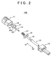
FIG. 2 is an exploded perspective view of a stop lamp switch according to a first embodiment, which does not form part of the present invention; -
FIG. 3 is a perspective view showing the assembled condition of a stop lamp switch according to the first embodiment, which does not form part of the present invention; -
FIG. 4 is a side view of the reed switch and the terminals; -
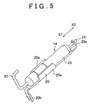
FIG. 5 is a perspective view of the reed switch and the terminals; -
FIG. 6A to FIG. 6C are drawings that depict the operation of a stop lamp switch according to the first embodiment, which does not form part of the present invention; -
FIG. 7A and FIG. 7B are cross-sectional views of the configuration and operation of a stop lamp switch according to a second embodiment, which does not form part of the present invention; -
FIG. 8A to FIG. 8C show in enlarged form the region of the case of a stop lamp switch according to a third embodiment, which does not form part of the present invention; -
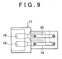
FIG. 9 shows in enlarged form the case of a stop lamp switch according to the third embodiment, which does not form part of the present invention, with the blocking member removed; -
FIG. 10 is a perspective view, shown in enlarged form, of the region of the case of a stop lamp switch according to a fourth embodiment, which does not form part of the present invention; -
FIG. 11A and FIG. 11B are perspective views showing the blocking member provided in a stop lamp switch according to the fourth embodiment, which does not form part of the present invention; -
FIG. 12 is a perspective view showing in enlarged form the case of a stop lamp switch according to the fourth embodiment, which does not form part of the present invention, with the blocking member removed; -
FIG. 13A and FIG. 13B are cross-sectional views of the configuration and operation of a stop lamp switch according to a fifth embodiment, which does not form part of the present invention; -
FIG. 14A and FIG. 14B are cross-sectional views of the configuration and operation of a stop lamp switch according to the present invention; and -
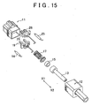
FIG. 15 is an exploded perspective view of the stop lamp switch according to the present invention. - In preamble, several stop lamp switches that do not form part of the present invention are described below, with references made to the accompanying drawings.
-
FIG. 1A and FIG. 1B are drawings depicting the principle of a stop lamp switch, which does not form part of the present invention.FIG. 1A shows the condition of astop lamp switch 10A when the brake pedal is not depressed (pedal non-operated condition) andFIG. 1B shows the condition of thestop lamp switch 10A when the brake pedal is depressed (pedal operated condition). - The
stop lamp switch 10A generally has a case (enclosure) 1, ahousing 12, an actuatingshaft 13, areed switch 14, amagnet 15, and a blockingmember 16 and the like. Thestop lamp switch 10A is disposed to make contact with the brake pedal, and the actuatingshaft 13 follows the movement of the brake pedal as the brake pedal is depressed and released, thereby switching thereed switch 14 on and off to light and extinguish a stop lamp. - An internal space is formed by combining the
case 11 and thehousing 12. Thereed switch 14 andconnector terminals 19 are disposed in thecase 11, and the actuatingshaft 13 and themagnet 15 are disposed in thehousing 12. - The
reed switch 14 hasreeds glass tube 23. Part of eachreed glass tube 23 and is connected to aconnector terminal 19. Theconnector terminals 19 are connected to stop lamp drive circuit (not illustrated) that causes the stop lamp to light up. - The actuating
shaft 13 is movably mounted in thehousing 12 in the direction indicated by the arrows X1 and X2 in drawing. Ahousing space 18 opening in the X1 direction is provided in theactuating shaft 13. Thereed switch 14 is positioned within thehousing space 18. The size of thehousing space 18 is established so that even if the actuatingshaft 13 moves in the X1 and X2 directions accompanying movement of the brake pedal, there is no influence on thereed switch 14. The actuatingshaft 13 is constantly impelled in the direction of arrow X2 by aspring 17. - The
magnet 15 is disposed in thehousing 12 to sandwich thereed switch 14 with N and S poles in opposition. Therefore, when the blockingmember 16 is not present between thereed switch 14 and themagnet 15, the magnetic field generated by themagnet 15 acts on thereeds glass tube 23, so that thereeds - The blocking
member 16 is a cylindrical member made of a magnetic material capable of blocking a magnetic field, and is disposed on theactuating shaft 13. Thus, the blockingmember 16 moves in the X1 and X2 directions with the movement of the actuatingshaft 13. - When the brake pedal is not operated, the actuating
shaft 13 shown inFIG. 1A moves in the direction of the arrow X1 and the blockingmember 16 moves to a position between thereed switch 14 and the magnet 15 (first position). Thus, the blockingmember 16 blocks the magnetic field of themagnet 15 so that the magnetic field does not act on thereed switch 14. For this reason, thereed switch 14 is in the off (open) condition, and the stop lamp is in the extinguished condition. - In contrast, when the brake pedal is operated, the actuating
shaft 13 moves in the direction of the arrow X2 by the force of thespring 13, which also moves the blockingmember 16 in the X2 direction. For this reason, as shown inFIG. 1B , the blockingmember 16 moves away from between thereed switch 14 and themagnet 15, and to a position that allows thereed switch 14 and themagnet 15 to come into direct opposition (second position). The magnetic field of themagnet 15 therefore acts on thereed switch 14 and thereed switch 14 goes into the on (closed) condition. For this reason, the stop lamp is lighted via the stop lamp drive circuit connected to theconnector terminals 19. - The
stop lamp switch 10A according to the foregoing embodiment uses a reed switch as the contacts, so that other members do not come into contact with thereeds reeds glass tube 23. - For this reason, in the
stop lamp switch 10A according to this embodiment, there are no moving parts at the sealed part protecting the contacts so that no damage occurs to the sealed part. Also, because thereed switch 14 contacts are disposed within theglass tube 23, the interior of which is either a vacuum or filled with an inert gas, impurities do not enter theglass tube 23. It is therefore possible to achieve astop lamp switch 10A having improved reliability and long life. - By providing a
housing space 18 in theactuating shaft 13 and adopting a configuration in which thereed switch 14 is inserted into the ahousing space 18, it is possible to reduce the length of thestop lamp switch 10A in the direction of arrows X1 and X2 than a configuration in which thereed switch 14 is not inserted. - Specifically, it is possible to shorten the
stop lamp switch 10A by the distance thereed switch 14 is inserted into the actuatingshaft 13. By doing this, it is possible to improve the ease of mounting to the brake pedal installation location, which is generally in cramped quarters. Also, the operating effect of thestop lamp switch 10A shown inFIG. 1A and FIG. 1B can be achieved by the stop lamp switches 10B to 10F which do not form part of the present invention, to be described below. - Stop lamp switches 10B to 10F, which do not form part of the present invention and based on the above-described principle will now be described.
FIG. 2 to FIG. 13B show stop lamp switches 10B to 10F according to the first to fifth embodiments. InFIG. 2 to FIG. 13B , the same or corresponding elements as inFIG. 1A and FIG. 1B are assigned the same reference numerals and will not be repeated described herein. - The
stop lamp switch 10B according to the first embodiment will first be described, with reference made toFIG. 2 to FIG. 6C . As shown inFIG. 2 , a pair ofconnector terminals 19 is inserted into and integrally with the case 11 (these being shown separated from thecase 11 in the drawings). Thereed switch 14 is connected to the pair ofconnector terminals 19.FIG. 4 andFIG. 5 show enlarged views of thereed switch 14. In this embodiment, thereed switch 14 is mounted on a terminal 20. - The terminal 20 is made of an electrically conductive material, and is integrally formed with a holding
member 20a, aterminal part 20b, and a connectingpart 20c. The holdingmember 20a sandwiches theglass tube 23 to hold thereed switch 14. - When this is done, the position of the holding
member 20a is established at a position that is offset from the contacts disposed inside theglass tube 23. By doing this, it is possible to apply the magnetic field of themagnet 15 to the contacts (reeds 21 and 22) inside theglass tube 23, without being hindered by the terminal 20. - The connecting
part 20c, which extends outside of theglass tube 23 in the direction of arrow X2, is connected to thereed 22 of thereed switch 14. Theterminal part 20b is bent into an L-shape and is electrically connected to theconnector terminals 19. Thereed 21 of thereed switch 14 that extends in the X1 direction is also bent into an L-shape and electrically connected to aconnector terminal 19. - The
magnet 15 is substantially ring shaped, and is fixed to thehousing 12 by pressing it into thehousing 12. Themagnet 15 is disposed at outside of thereed switch 14. The blockingmember 16 is cylindrically shaped and is pressed into the actuatingshaft 13. Ahousing space 18 is formed in theactuating shaft 13 and the terminal 20 (including the reed switch 14) may be inserted into thehousing space 18. - In the
stop lamp switch 10B, because theconnector terminals 19 are formed so as to be inserted into thecase 11, thereed switch 14 is held by the terminal 20, themagnet 15 is fixed to thehousing 12 by pressing thereinto, and the blockingmember 16 is pressed into the actuatingshaft 13, it is possible to facilitate assembly. Also, as shown inFIG. 3 , the assembledstop lamp switch 10B is compact, making it easy to mount to the brake pedal installation location. -
FIG. 6A to FIG. 6C depict the operation of thestop lamp switch 10B.FIG. 6A shows thestop lamp switch 10B when the brake pedal is not operated. The actuatingshaft 13, in opposition to the force of thespring 17, is moved in the direction of the arrow X1 in the drawing by the brake pedal, and in this condition the blockingmember 16 provided in theactuating shaft 13 is positioned between themagnet 15 and thereed switch 14. - For this reason, the blocking
member 16 blocks the magnetic field of themagnet 15, so that the magnetic field does not act on thereed switch 14. Thereed switch 14 therefore goes into the off (open) condition, and the stop lamp is in the extinguished condition. In this condition, thereed switch 14 is inserted the most deeply into thehousing space 18. -
FIG. 6B shows the condition in which the brake pedal starts to be depressed, whereby the actuatingshaft 13 moves in the direction of the arrow X2 by the force of thespring 17 to the position at which the contacts are switched. The contact switching position is the limiting position at which the blockingmember 16 can block the magnetic field generated by themagnet 15. If the pedal is depressed further from this condition, the actuatingshaft 13 moves beyond the contact switching position in the direction of the arrow X2. - As shown in
FIG. 6C , when the brake pedal is depressed the actuatingshaft 13 is moved in the direction of the arrow X2. In this condition, the blockingmember 16 is removed from the position between thereed switch 14 and themagnet 15, so that thereed switch 14 and themagnet 15 are in direct opposition. Thus, the magnetic field of the magnet 15 (indicated by the downward-pointing arrow in the drawing) acts on thereed switch 14, and the stop lamp is lighted via the stop lamp drive circuit connected to theconnector terminals 19. - The
stop lamp switch 10C according to the second embodiment, which does not form part of the present invention will now be described. -
FIG. 7A and FIG. 7B show thestop lamp switch 10C according to the second embodiment. A feature of thestop lamp switch 10C of the second embodiment is that it has tworeed switches members magnets reed switch 14 is used to turn the brake lamp on and off, as in the case of the first embodiment. - The
reed switch 25, in contrast, functions as a brake switch that detects the operation of the brake pedal. As described later, thereed switch 25 is on (closed)when the brake pedal is not depressed, and off (open)when the brake pedal is depressed. - The
reed switch 25 is connected to theconnector terminals 26, and theconnector terminals 26 are connected, for example, to an engine control unit (ECU). The ECU detects the depression of the brake pedal by a brake signal sent from thereed switch 25. In this embodiment thereed switch 25 is mounted on thecase 11 in a direction perpendicular to the plane of the drawing, in order to prevent an increase in size in the directions of the arrows X1 and X2. - The
first magnet 15A is formed substantially the same as themagnet 15 of thestop lamp switch 10B in the first embodiment. That is, thefirst magnet 15A is disposed in thehousing 12 opposite thereed switch 14. In contrast, thesecond magnet 15B is fixed to thecase 11 opposite thereed switch 25. The position of thesecond magnet 15B is established so that it is possible for the magnetic field of thesecond magnet 15B to act on thereed switch 25. - The
first blocking member 16A is formed substantially the same as the blockingmember 16 of thestop lamp switch 10C of the first embodiment. That is, thefirst blocking member 16A is fixed to theactuating shaft 13, and when the brake pedal is not operated, the actuatingshaft 13 is moved in the X1 direction, (shown inFIG. 7A ), and the actuatingshaft 13 blocks the magnetic field of themagnet 15, thereby preventing the magnetic field from acting on thereed switch 14. When the brake pedal is depressed (shown inFIG. 7B ), the actuatingshaft 13 is moved in the X2 direction, and thefirst blocking member 16A moves away from between thefirst magnet 15A and thereed switch 14, thereby allowing the magnetic field of themagnet 15 to act on thereed switch 14. - In contrast to the above, the
second blocking member 16B is made of a magnetic material that can block a magnetic field, and has acylindrical part 30 and aflanged part 31. Thesecond blocking member 16B may also be fixed to theactuating shaft 13, at a position that is farther in the X1 direction from the position where thefirst blocking member 16A is fixed. - An
aperture 27 is formed at a prescribed position on thesecond blocking member 16B. Theaperture 27 is formed so that, when the brake pedal is not depressed the actuatingshaft 13 is moved in the X1 direction (shown inFIG. 7A ), and thereed switch 25 and thesecond magnet 15B are in opposition. Therefore, when the brake pedal is not depressed the magnetic field of thesecond magnet 15B acts on thereed switch 25, so that thereed switch 25 is on. - In contrast, when the brake pedal is depressed, the actuating
shaft 13 is moved in the X2 position (shown inFIG. 7B ), and thesecond blocking member 16B is positioned between thereed switch 25 and thesecond magnet 15B; thus, blocking the magnetic field of thesecond magnet 15B and preventing the magnetic field from acting on thereed switch 25. In the pedal operated condition, therefore, the magnetic field of thesecond magnet 15B does not act on thereed switch 25, and thereed switch 25 is off. - According to the
stop lamp switch 10C of the second embodiment, it is possible to extract two signals from the reed switches 14, 15 simultaneously. For this reason, it is possible to obtain two signal from a singlestop lamp switch 10C. Also, by appropriately selecting the position of theaperture 27 in thesecond blocking member 16B, it is possible to have thereed switch 25 be in the on condition either in the pedal operated condition or the pedal non-operated condition, thereby increasing the degree of freedom in the setting of thestop lamp switch 10C. - The third embodiment, which does not form part of the present invention, will now be described.
-
FIG. 8A to FIG. 9 show thestop lamp switch 10D according to the third embodiment.FIG. 8A to FIG. 9 show in enlarged only the characteristic region of thecase 11 of thestop lamp switch 10D, and descriptions of thehousing 12 and description of the actuatingshaft 13 will be omitted herein. - The case of the third embodiment is similar to that of the second embodiment, and has two
reed switches FIG. 9 , are disposed in a parallel row in thecase 11. - In this embodiment, one blocking
member 16 is provided for bothreed switches magnet 15 has the form of a flat plate, and thismagnet 15 is also provided in common for the reed switches 14, 25. - The blocking
member 16 is moveable in the directions of the arrows X1 and X2 in the drawing, by means of the actuating shaft 13 (not illustrated). The side edges of the blockingmember 16 are bent inward, as shown inFIG. 8C , the bent parts thereof are engaged with thecase 11 to enable sliding in theguide grooves 28 formed in thecase 11 and that extend in the X1 and X2 directions. The blockingmember 16 can move in the directions of the arrows X1 and X2 relative toreed switches shaft 13. -
Apertures member 16. Theaperture 27A is formed to as to oppose thereed switch 14, and theaperture 27B is formed so as to oppose thereed switch 25. Specifically, when the brake pedal is not depressed (shown inFIG. 8A ), the blocking member 16 (actuating shaft 13) is moved in the direction of the arrow X1, theaperture 27A moves away from the contact position of thereed switch 14, and theaperture 27B moves to a position opposite the contacts of thereed switch 25. - When the brake pedal is depressed, the blocking
member 16 is moved in the direction of the arrow X2, and theaperture 27A is set at a position opposite the contacts of thereed switch 14 and theaperture 27B is set at a position that is removed from the position of the contacts of thereed switch 25. The magnetic field of themagnet 15 selectively act on thereed switch 14 and thereed switch 25. - In the
stop lamp switch 10D having the above-noted configuration, when the brake pedal is not depressed the magnetic field of themagnet 15 acts on thereed switch 25 via theaperture 27B, so that thereed switch 25 is in the on (closed) condition. In contrast, thereed switch 14 is off (open) because the blockingmember 16 blocks the magnetic field of themagnet 15. - On the other hand, when the brake pedal is depressed, the magnetic field of the
magnet 15 acts on thereed switch 14 via theaperture 27A, so that thereed switch 14 is in the on (closed) condition. In contrast, thereed switch 25 is in the off (open) condition because the blockingmember 16 blocks magnetic field of themagnet 15. - In the
stop lamp switch 10D of the above-noted third embodiment as well, it is possible obtain two signals simultaneously from the tworeed switches apertures stop lamp switch 10D. Additionally, because only onemagnet 15 is required, there is a reduction in the number of parts in comparison with thestop lamp switch 10C of the second embodiment. - The fourth embodiment, which does not form part of the present invention will now be described.
-
FIG. 10 to FIG. 12 are drawings for describing thestop lamp switch 10E according to the fourth embodiment.FIG. 10 shows in enlarged the region of thecase 11 of thestop lamp switch 10E, and the description of thehousing 12 is omitted herein. - The
stop lamp switch 10E of this embodiment, in addition to having themagnet 15 disposed to the inside of the blockingmember 16, has the reed switches 14, 25 disposed the outside of the blockingmember 16.FIG. 12 is an enlarged view of the region of themagnet 15 of thestop lamp switch 10E. As shown in this drawing, asingle magnet 15 is disposed in thecase 11, within the blockingmember 16. - The blocking
member 16, as shown in enlarged form inFIG. 11A and FIG. 11B , has a U-shapedprofile, and is movable in the directions of the arrows X1 and X2, guided by theguide grooves 28 formed in thecase 11. Because the blockingmember 16 is fixed to the bottom end of the actuatingshaft 13, blockingmember 16 moves in the X1 and X2 directions with the movement of the actuatingshaft 13 in the X1 and X2 directions. -
Apertures FIG. 11A ). The positions at which theapertures apertures - In the
stop lamp switch 10E, therefore, when the brake pedal is not depressed the magnetic field of themagnet 15 acts on thereed switch 25 via theaperture 27B, so that thereed switch 25 is in the on (closed) condition. In contrast, thereed switch 14 is in the off (open) condition, because the blockingmember 16 blocks the magnetic field of themagnet 15. - On the other hand, when the brake pedal is depressed the magnetic field of the
magnet 15 acts on thereed switch 14 via theaperture 27A, so that thereed switch 14 is in the on (closed) condition, while thereed switch 25 is in the off (open) condition because the blockingmember 16 blocks the magnetic field of themagnet 15. - In this embodiment, by disposing the
magnet 15 on the inside of the blockingmember 16, it is possible with acompact magnet 15 to apply a magnetic field to the plurality ofreed switches stop lamp switch 10E. Also, because of the tworeed switches - The fifth embodiment, which does not form part of the present invention, will now be described.
-
FIG. 13A and FIG. 13B show astop lamp switch 10F according to the fifth embodiment. While the foregoing described embodiments had blockingmembers members - In this embodiment, the
magnet 15 is provided on aflange part 32 formed on the end part of the actuatingshaft 13 in the X1 direction. Therefore, themagnet 15 moves in the X1 and X2 directions with the movement of the actuatingshaft 13 in the X1 and X2 directions. Also, thereed switch 25 is disposed in thecase 11, similar to the other embodiment, but is disposed at a position that is opposite the magnet 15 (in the X1 and X2 direction). - When the brake pedal is not depressed, therefore, the actuating
shaft 13 is moved in the X1 direction, as shown inFIG. 13A , and themagnet 15 approaches thereed switch 25, so that the magnetic field of themagnet 15 acts on thereed switch 25, causing it to be in the on (closed) condition. In contrast, when the brake pedal is depressed, the actuatingshaft 13 is moved in the X2 direction, as shown inFIG. 13B , and themagnet 15 moves away from thereed switch 25, so that the magnetic field of themagnet 15 does not act on thereed switch 25, causing thereed switch 25 to be in the off (open) condition. - The
reed switch 14 is configured so that it can be inserted into thehousing space 18 formed in theactuating shaft 13. Themagnet 15 is provided on the end part in the X1 direction of the actuatingshaft 13. When the brake pedal is not depressed, therefore, as shown inFIG. 13A , most of thereed switch 14 is inside thehousing space 18, and the magnetic field of themagnet 15 does not act on the contacts of thereed switch 14. Thereed switch 14, therefore, is in the off (open) condition when the brake pedal is not depressed. - In contrast to this, when the actuating
shaft 13 is moved in the X2 direction by the depressing of the brake pedal, themagnet 15 also moves in concert in the X2 direction. By moving the actuatingshaft 13 in the X2 direction, thereed switch 14 that is fixed to thecase 11 moves out of thehousing space 18 so as to be exposed. - When the brake pedal is depressed, as shown in
FIG. 13B , themagnet 15 is opposite the reed switch 14 (when considered in the Y1, Y2 direction).
Therefore, when the brake pedal is depressed, thereed switch 14 is closed. - As noted above, the
stop lamp switch 10F of this embodiment is able to switch the reed switches 14, 25 on and off by asingle magnet 15, without using blocking members. It is therefore possible to reduce the number of parts compared to the other embodiments, to facilitate assembly, and to achieve compactness. - The present invention will now be described.
-
FIG. 14 to FIG. 15 show astop lamp switch 10G according to a variation of the fifth embodiment, which illustrates the present invention. Thestop lamp switch 10G of this variation is similar to thestop lamp switch 10F of the fifth embodiment, switches the contacts of the reed switches 14, 25 on and off without using a blocking member. - The
stop lamp switch 10G of this variation, however, differs from thestop lamp switch 10F of the fifth embodiment in that it uses a ring-shaped magnet as themagnet 15, and in that thereed switch 25 extends in the movement direction of the actuating shaft 13 (X1 and X2 directions). - By disposing the
reed switch 25 to extend in the X1 and X2 directions as in this embodiment, thereed switch 14 and thereed switch 25 are substantially parallel. The contact position of thereed switch 14 and the contact position of thereed switch 25 are offset in the X1 and X2 directions. Specifically, the contact position of the reed switch 14 (position at which the magnetic field switches the switch on and off) is offset by a prescribed amount in the X2 direction from the contact position of thereed switch 25. - In this variation as noted above, a ring-shaped
magnet 15 is used, and thereed switch 14 is disposed to the inside of this ring-shapedmagnet 15, with thereed switch 25 disposed to the outside of the ring-shapedmagnet 15. Because the ring-shapedmagnet 15 is mounted to theactuating shaft 13, and the reed switches 14, 25 are fixed to thecase 11, by the actuatingshaft 13 moving in the X1 and X2 directions, themagnet 15 moves in the X1 and X2 directions relative to the reed switches 14, 25. - When the brake pedal is not operating, the actuating
shaft 13 is moved in the X1 direction, as shown inFIG. 14A , and the ring-shapedmagnet 15 approaches the contacts of thereed switch 25. The result is that the magnetic field of the ring-shapedmagnet 15 acts on the contacts of thereed switch 25, so that thereed switch 25 goes into the on (closed) condition. When this occurs, because the contacts of thereed switch 14 are offset from the contacts of thereed switch 25, the magnetic field of the ring-shapedmagnet 15 does not act on the contacts of thereed switch 14, so that thereed switch 14 is in the off (open) condition. - On the other hand, when the brake pedal is operated, the actuating
shaft 13 is moved in the X2 direction, as shown inFIG. 14B , the ring-shapedmagnet 15 approaches the contacts of thereed switch 14. The result is that the magnetic field of the ring-shapedmagnet 15 acts on the contacts of thereed switch 14, so that thereed switch 14 is closed. When this occurs, because the contacts of thereed switch 25 are offset from the contacts of thereed switch 14, the magnetic field of the ring-shapedmagnet 15 does not act on the contacts of thereed switch 25, so that thereed switch 25 is in the off (open) condition. - As noted above, the
stop lamp switch 10G of this variation, similar to thestop lamp switch 10F of the fifth embodiment, may switch tworeed switches - In this variation, because the
magnet 15 is ring-shaped and thereed switch 14 is disposed inside the ring-shapedmagnet 15 and thereed switch 25 is disposed outside the ring-shapedmagnet 15, it is possible to use acompact magnet 15 to have a magnetic field act on each of the reed switches 14, 25, thereby making it possible to achieve compactness in thestop lamp switch 10G, while achieving reliable switching operation. - The on/off timing of the
reed switch 14 accompanying movement of the actuatingshaft 13 and the on/off timing of thereed switch 25 accompanying movement of the actuatingshaft 13 may be varied by adjusting the contact positions of thereed switch 14 and thereed switch 25 within thecase 11 and thehousing 12. In particular, if thereed switch 14 and thereed switch 25 are disposed in parallel, it is possible to perform this adjustment for each of thereed switch 14 and thereed switch 25. - In this variation as well, the
reed switch 14 is inserted inside the actuatingshaft 13. For this reason, it is possible to set the contact position of thereed switch 14 without regard to the movement region of the actuatingshaft 13, and therefore possible to increase the degree of freedom of setting the on/off timing of the reed switches 14, 25. - Although each of the foregoing examples show the use of one or two reed switches, any number of reed switches may be used as appropriate.
- According to the present invention, by using a reed switch and operating the contacts in a non-contacting manner, it is possible to eliminate moving parts in a sealing part and prevent damage to the sealing part. Because the contacts of the reed switch are disposed in a glass tube, the interior of which is either a vacuum or filled with an inert gas, there is no intrusion of impurities into the glass tube.
Claims (13)
- A switch (10F) suitable for a stop lamp, comprising:an enclosure (11);a first reed switch (14) and a second reed switch (25), disposed in the enclosure (11);an actuating shaft (13) that is movable along an axial direction of the enclosure (11); anda ring-shaped magnet (15), disposed on the actuating shaft (13), the first reed switch (14) being disposed inside the ring-shaped magnet (15), wherein a magnetic field of the ring-shaped magnet (15) opens and closes contacts of the first and second reed switches (14, 25); the ring-shaped magnet (15) moves with the movement of the actuating shaft (13), between a first position, at which a magnetic field is not applied to the first reed switch (14) and a second position, at which the magnetic field is applied to the first reed switch (14); and the reed switch (14) disposed inside the ring-shaped magnet (15) is adapted to be switched on and off to light and extinguish a stop lamp; the switch being characterized in that the second reed switch (25) is disposed outside the ring-shaped magnet (15), and in that, when the ring-shaped magnet (15) is at the first position, a magnetic field of the ring-shaped magnet (15) is applied to the second reed switch (25) by the ring-shaped magnet (15), and when the ring-shaped magnet (15) is at the second position, a magnetic field of the ring-shaped magnet (15) is not applied to the second reed switch (25).
- The switch (10F) according to claim 1, wherein multiple first reed switches (14) are provided at locations where the magnetic field of the ring-shaped magnet (15) reaches.
- The switch (10G) according to claim 1 or 2, wherein a contact position of the first reed switch (14) is offset in the axial direction of the actuating shaft (13) relative to a contact position of the second reed switch (25).
- The switch (10F, 10G) according to any one of claim 1 to claim 3, wherein the actuating shaft (13) covers the first reed switch (14).
- The switch (10F, 10G) according to any one of claim 1 to claim 3, wherein a housing space (18) is formed in the actuating shaft (13), and wherein the first reed switch (14) is insertable within the housing space (18).
- The switch (10A, 10C, 10F, 10G) according to any one of claim 1 to claim 5, wherein the first reed switch (14) is elongated and extends in a parallel direction relative to the axial direction of the actuating shaft (13).
- The switch (10C, 10F, 10G) according to any one of claims 1 to 6, wherein the second reed switch (25) is elongated and extends in a parallel direction relative to the axial direction of the actuating shaft (13).
- The switch (10C, 10F, 10G) according to any one of claims 1 to 7, wherein the reed switch (14) disposed inside the ring-shaped magnet (15) is supported by a holding member (20a) which extends from a connector terminal (19).
- The switch (10C, 10F, 10G) according to claim 8, wherein said holding member (20a), extends from said connector terminal (19) to sandwich the first reed switch and is integrally formed with a connecting part (20c) connected to a reed of the first reed switch.
- The switch (10C, 10F, 10G) according to any one of claims 1 to 9, wherein the second reed switch (25) is adapted to be switched on and off to send a brake signal to a brake lamp of a vehicle.
- The switch (10C, 10F, 10G) according to any one of claims 1 to 10, further including a first circuit to light and extinguish the stop lamp and a second circuit to send a brake signal.
- The switch (10C, 10F, 10G) according to any one of claims 1 to 11, wherein in the axial direction of the actuating shaft (13), the first reed switch (14) partially overlaps with the second reed switch (25).
- Assembly comprising a stop lamp, and a switch (10C, 10F, 10G) according to any one of claims 1 to 11, operated by a brake pedal, wherein the first reed switch (14) is switched on to light the stop lamp when the brake pedal is depressed.
Applications Claiming Priority (2)
| Application Number | Priority Date | Filing Date | Title |
|---|---|---|---|
| JP2006114976A JP4190544B2 (en) | 2006-04-18 | 2006-04-18 | Stop lamp switch |
| PCT/IB2007/001021 WO2007119169A1 (en) | 2006-04-18 | 2007-04-16 | Stop lamp switch |
Publications (2)
| Publication Number | Publication Date |
|---|---|
| EP2018296A1 EP2018296A1 (en) | 2009-01-28 |
| EP2018296B1 true EP2018296B1 (en) | 2011-11-30 |
Family
ID=38337843
Family Applications (1)
| Application Number | Title | Priority Date | Filing Date |
|---|---|---|---|
| EP07734340A Ceased EP2018296B1 (en) | 2006-04-18 | 2007-04-16 | Stop lamp switch |
Country Status (5)
| Country | Link |
|---|---|
| US (1) | US7924125B2 (en) |
| EP (1) | EP2018296B1 (en) |
| JP (1) | JP4190544B2 (en) |
| CN (1) | CN101426667A (en) |
| WO (1) | WO2007119169A1 (en) |
Cited By (2)
| Publication number | Priority date | Publication date | Assignee | Title |
|---|---|---|---|---|
| DE102012108991A1 (en) * | 2012-09-24 | 2014-05-15 | BSS Baumann Sicherheitssysteme GmbH | Switching contact structure for e.g. door lock, has short-circuit element that is arranged at movable switching element, such that magnetic field of magnet to reed contact portion is shielded during first position of switching element |
| DE102015102947A1 (en) * | 2015-03-02 | 2016-09-08 | Endress + Hauser Gmbh + Co. Kg | Field device of automation technology |
Families Citing this family (11)
| Publication number | Priority date | Publication date | Assignee | Title |
|---|---|---|---|---|
| JP4906113B2 (en) * | 2007-10-03 | 2012-03-28 | 株式会社東海理化電機製作所 | Switch device |
| GB2466305B (en) * | 2008-12-19 | 2015-06-03 | Autoflame Eng Ltd | Burner installation |
| CN101996783A (en) * | 2010-10-19 | 2011-03-30 | 奇瑞汽车股份有限公司 | Contact seal type stop lamp switch |
| CN102394186A (en) * | 2011-07-21 | 2012-03-28 | 安徽江淮汽车股份有限公司 | Switch for automobile brake lamp |
| TWI422751B (en) * | 2011-08-11 | 2014-01-11 | Wistron Corp | Magnetic switch device and electronic device having the same |
| CN103873041A (en) * | 2012-12-12 | 2014-06-18 | 富泰华工业(深圳)有限公司 | Magnetic induction switch and electronic device with magnetic induction switch |
| US10377297B2 (en) * | 2016-12-09 | 2019-08-13 | Dongwoun Industrial Co., Ltd. | Lamp switch for parking brake |
| CN111379763A (en) * | 2018-12-31 | 2020-07-07 | 重庆海峻机电设备有限公司 | Motor cabinet with position finding device |
| US20200251296A1 (en) * | 2019-02-06 | 2020-08-06 | Honeywell International Inc. | Reed switch assembly having a customizable length of activation |
| US11657992B2 (en) | 2019-05-06 | 2023-05-23 | Jeffrey A. Stallmer | Protective cover assembly for magnetically actuating an electrical wall switch |
| DE102023104181A1 (en) * | 2023-02-21 | 2024-08-22 | Te Connectivity Solutions Gmbh | Arrangement and method for status monitoring of a switch for high currents and/or high voltages |
Citations (1)
| Publication number | Priority date | Publication date | Assignee | Title |
|---|---|---|---|---|
| GB2255673A (en) * | 1991-04-26 | 1992-11-11 | Aisin Seiki | Liquid reservoir. |
Family Cites Families (36)
| Publication number | Priority date | Publication date | Assignee | Title |
|---|---|---|---|---|
| DE1127957B (en) * | 1959-12-04 | 1962-04-19 | Int Standard Electric Corp | Switching device with a large number of parallel armature contacts arranged in protective tubes |
| US3200645A (en) * | 1963-05-22 | 1965-08-17 | Gen Electric | Electric position sensor |
| US3243544A (en) * | 1964-12-09 | 1966-03-29 | Allen Bradley Co | Convertible relay control station |
| DE1590084C3 (en) * | 1966-02-01 | 1974-02-28 | Robert Bosch Gmbh, 7000 Stuttgart | Magnetic field operated contactor acting as a break contact |
| US3419695A (en) * | 1966-03-23 | 1968-12-31 | Stewart Warner Corp | Float switch assembly |
| US3437771A (en) * | 1967-05-09 | 1969-04-08 | Roylyn Inc | Liquid level sensing means |
| FR2057538A5 (en) * | 1969-04-25 | 1971-05-21 | Beimler Lokomotivbau | |
| US3701064A (en) * | 1970-12-29 | 1972-10-24 | Fujitsu Ltd | Push-button switch |
| US3681724A (en) * | 1971-07-01 | 1972-08-01 | Ibm | Mechanically actuated electric switch assembly |
| JPS4948953B2 (en) | 1971-08-27 | 1974-12-24 | ||
| US3826139A (en) * | 1973-03-19 | 1974-07-30 | Laval Turbine | Liquid level indicating apparatus |
| FR2345700A2 (en) * | 1976-03-23 | 1977-10-21 | Petrole Service Sa | IMPROVEMENTS TO MAGNETIC DETECTOR DEVICES OF THE POSITION OF A MOBILE ELEMENT |
| DE2418860A1 (en) * | 1974-04-19 | 1975-10-30 | Kuebler Impulsgeraete | TRANSDUCER FOR LEVEL INDICATOR OF LIQUIDS |
| US4056979A (en) * | 1975-10-31 | 1977-11-08 | B/W Controls Inc. | Liquid level sensor |
| JPS52106576A (en) | 1976-03-03 | 1977-09-07 | Okura Yusoki Co Ltd | Store and pick up apparatus |
| JPS52143669A (en) | 1976-05-24 | 1977-11-30 | Sesupa Insutorumentsu Isutabur | Support body and method of transferring support body |
| MX145896A (en) * | 1977-11-09 | 1982-04-19 | Fernando D Quintero Alvarez | IMPROVEMENTS IN INDICATORS FOR LEVEL MEASUREMENTS FILLING AND EMPTYING OF LIQUIDS IN TANKS AND CONTAINERS BY SENSORS OPERATED BY MAGNETIC FLOAT |
| US4186419A (en) * | 1978-11-20 | 1980-01-29 | Sims Bobby H | Apparatus for monitoring and controlling liquid level |
| JPS55109320A (en) | 1979-02-15 | 1980-08-22 | Tokyo Shibaura Electric Co | Multipolar type auxiliary switch |
| US4543569A (en) * | 1983-05-12 | 1985-09-24 | Audiopro Marketing | Vehicular alarm triggering system |
| DE3410858A1 (en) * | 1984-03-23 | 1985-10-03 | Alfred Teves Gmbh, 6000 Frankfurt | ELECTRIC SWITCH |
| JPS616457A (en) | 1984-06-20 | 1986-01-13 | Daihatsu Motor Co Ltd | Lock-up clutch apparatus for transmission |
| JPS62104337A (en) | 1985-10-31 | 1987-05-14 | Nec Corp | Detecting circuit for frame pulse |
| US4805066A (en) * | 1987-09-17 | 1989-02-14 | Robert Mergenthaler | Hybrid float switch |
| US4976146A (en) * | 1988-10-19 | 1990-12-11 | Senghaas Karl A | Liquid level measuring apparatus |
| US5025827A (en) * | 1990-04-12 | 1991-06-25 | Evans Weng | Structure of fluid level controller of piping type |
| JPH04136829A (en) | 1990-09-28 | 1992-05-11 | Olympus Optical Co Ltd | Range-finder device for moving body |
| US5347864A (en) * | 1993-04-12 | 1994-09-20 | Electrolab, Inc. | Liquid level measuring apparatus |
| JPH1064360A (en) | 1996-08-19 | 1998-03-06 | Somic Ishikawa:Kk | Switch |
| JPH11167035A (en) | 1997-12-04 | 1999-06-22 | Oki Electric Ind Co Ltd | Optical function element and optical coupling method |
| DE20113027U1 (en) * | 2001-08-04 | 2001-11-22 | Pack, Oliver, 51588 Nümbrecht | Switch and position detector |
| JP2004071452A (en) | 2002-08-08 | 2004-03-04 | Matsushita Electric Ind Co Ltd | Stop lamp switch |
| JP4136829B2 (en) | 2003-07-04 | 2008-08-20 | 株式会社八光 | Medical collection bag |
| FR2872767B1 (en) * | 2004-07-07 | 2008-01-11 | Bosch Gmbh Robert | MASTER CYLINDER COMPRISING MEANS FOR DETECTING THE DISPLACEMENT OF A MOBILE ELEMENT |
| JP2006092777A (en) | 2004-09-21 | 2006-04-06 | Niles Co Ltd | Solid state switch |
| US6998552B1 (en) * | 2005-07-27 | 2006-02-14 | Young-G Enterprise Corporation | Float-type liquid level switch assembly with light emitting elements |
-
2006
- 2006-04-18 JP JP2006114976A patent/JP4190544B2/en not_active Expired - Lifetime
-
2007
- 2007-04-16 EP EP07734340A patent/EP2018296B1/en not_active Ceased
- 2007-04-16 WO PCT/IB2007/001021 patent/WO2007119169A1/en not_active Ceased
- 2007-04-16 CN CNA2007800142405A patent/CN101426667A/en active Pending
- 2007-04-16 US US12/297,757 patent/US7924125B2/en not_active Expired - Fee Related
Patent Citations (1)
| Publication number | Priority date | Publication date | Assignee | Title |
|---|---|---|---|---|
| GB2255673A (en) * | 1991-04-26 | 1992-11-11 | Aisin Seiki | Liquid reservoir. |
Cited By (4)
| Publication number | Priority date | Publication date | Assignee | Title |
|---|---|---|---|---|
| DE102012108991A1 (en) * | 2012-09-24 | 2014-05-15 | BSS Baumann Sicherheitssysteme GmbH | Switching contact structure for e.g. door lock, has short-circuit element that is arranged at movable switching element, such that magnetic field of magnet to reed contact portion is shielded during first position of switching element |
| DE102012108991B4 (en) * | 2012-09-24 | 2016-07-21 | BSS Baumann Sicherheitssysteme GmbH | switching contact |
| DE102015102947A1 (en) * | 2015-03-02 | 2016-09-08 | Endress + Hauser Gmbh + Co. Kg | Field device of automation technology |
| US10264691B2 (en) | 2015-03-02 | 2019-04-16 | Endress+Hauser SE+Co. KG | Field device for automation technology |
Also Published As
| Publication number | Publication date |
|---|---|
| WO2007119169A1 (en) | 2007-10-25 |
| US20090237189A1 (en) | 2009-09-24 |
| EP2018296A1 (en) | 2009-01-28 |
| US7924125B2 (en) | 2011-04-12 |
| CN101426667A (en) | 2009-05-06 |
| JP4190544B2 (en) | 2008-12-03 |
| JP2007287529A (en) | 2007-11-01 |
Similar Documents
| Publication | Publication Date | Title |
|---|---|---|
| US7924125B2 (en) | Stop lamp switch | |
| EP1310968A2 (en) | Switch apparatus | |
| KR20030092811A (en) | A fuel filler door assembly for a vehicle | |
| US8129639B2 (en) | Emblem-unified trunk opening and closing device | |
| WO2018123223A1 (en) | Contact structure for switch, trigger switch and electric power tool | |
| US7439459B2 (en) | Switch device and steering switch apparatus equipped with the switch device | |
| US5714728A (en) | Electric switch | |
| US7978037B2 (en) | Switch device | |
| US6273593B1 (en) | Door and manually actuated vehicle interior lighting system | |
| HK1040428A1 (en) | An electrical switch gas-burner lighter | |
| US7485825B2 (en) | Push-type vehicle switch | |
| US8093976B2 (en) | Vehicle switch | |
| US20080121501A1 (en) | Switch structure having integrated damper for lighting glove box lamp | |
| JP5228900B2 (en) | Vehicle switch | |
| US8993903B2 (en) | Sealed dual plunger switch assembly with simultaneity | |
| KR101070028B1 (en) | Sliding button switch unit for a vehicle | |
| US7504919B1 (en) | Water resistant switch assembly | |
| CN1388549A (en) | Auxiliary switchgear for circuit breakers | |
| US20240355565A1 (en) | Electromagnetic relay | |
| JPH08153434A (en) | Sealed contact device | |
| JP2005019163A (en) | Relay device | |
| JP2005116446A (en) | Contamination prevention structure for pedal switch | |
| KR100348432B1 (en) | Push type On/off switch of vehicle | |
| CN100458993C (en) | Switch contact structure | |
| JPH0431700Y2 (en) |
Legal Events
| Date | Code | Title | Description |
|---|---|---|---|
| PUAI | Public reference made under article 153(3) epc to a published international application that has entered the european phase |
Free format text: ORIGINAL CODE: 0009012 |
|
| 17P | Request for examination filed |
Effective date: 20081017 |
|
| AK | Designated contracting states |
Kind code of ref document: A1 Designated state(s): AT BE BG CH CY CZ DE DK EE ES FI FR GB GR HU IE IS IT LI LT LU LV MC MT NL PL PT RO SE SI SK TR |
|
| AX | Request for extension of the european patent |
Extension state: AL BA HR MK RS |
|
| 17Q | First examination report despatched |
Effective date: 20090327 |
|
| DAX | Request for extension of the european patent (deleted) | ||
| RBV | Designated contracting states (corrected) |
Designated state(s): DE FR GB |
|
| GRAP | Despatch of communication of intention to grant a patent |
Free format text: ORIGINAL CODE: EPIDOSNIGR1 |
|
| RIN1 | Information on inventor provided before grant (corrected) |
Inventor name: MANABE, KYOHEIC/O MATSUO INDUSTRIES, INC. Inventor name: SEKITOMI, YUJIC/O MATSUO INDUSTRIES, INC. Inventor name: OKUMURA, MASAOC/O MATSUO INDUSTRIES, INC. Inventor name: NISHIGUCHI, MASAYUKIC/O TOYOTA JIDOSHA KABUSHIKI K |
|
| GRAS | Grant fee paid |
Free format text: ORIGINAL CODE: EPIDOSNIGR3 |
|
| RBV | Designated contracting states (corrected) |
Designated state(s): DE |
|
| RIN1 | Information on inventor provided before grant (corrected) |
Inventor name: SEKITOMI, YUJIC/O MATSUO INDUSTRIES,INC Inventor name: NISHIGUCHI, MASAYUKIC/O TOYOTA JIDOSHA KABUSHIKI K Inventor name: MANABE, KYOHEIC/O MATSUO INDUSTRIES, INC. Inventor name: OKUMURA, MASAOC/O MATSUO INDUSTRIES,INC. |
|
| RIN1 | Information on inventor provided before grant (corrected) |
Inventor name: NISHIGUCHI, MASAYUKIC/O TOYOTA JIDOSHA KABUSHIKI K Inventor name: OKUMURA, MASAOC/O MATSUO INDUSTRIES, INC. Inventor name: SEKITOMI, YUJIC/O MATSUO INDUSTRIES, INC. Inventor name: MANABE, KYOHEIC/O MATSUO INDUSTRIES, INC. |
|
| GRAA | (expected) grant |
Free format text: ORIGINAL CODE: 0009210 |
|
| AK | Designated contracting states |
Kind code of ref document: B1 Designated state(s): DE |
|
| REG | Reference to a national code |
Ref country code: DE Ref legal event code: R096 Ref document number: 602007019081 Country of ref document: DE Effective date: 20120216 |
|
| PLBE | No opposition filed within time limit |
Free format text: ORIGINAL CODE: 0009261 |
|
| STAA | Information on the status of an ep patent application or granted ep patent |
Free format text: STATUS: NO OPPOSITION FILED WITHIN TIME LIMIT |
|
| 26N | No opposition filed |
Effective date: 20120831 |
|
| REG | Reference to a national code |
Ref country code: DE Ref legal event code: R097 Ref document number: 602007019081 Country of ref document: DE Effective date: 20120831 |
|
| REG | Reference to a national code |
Ref country code: DE Ref legal event code: R084 Ref document number: 602007019081 Country of ref document: DE |
|
| PGFP | Annual fee paid to national office [announced via postgrant information from national office to epo] |
Ref country code: DE Payment date: 20220302 Year of fee payment: 16 |
|
| REG | Reference to a national code |
Ref country code: DE Ref legal event code: R119 Ref document number: 602007019081 Country of ref document: DE |
|
| PG25 | Lapsed in a contracting state [announced via postgrant information from national office to epo] |
Ref country code: DE Free format text: LAPSE BECAUSE OF NON-PAYMENT OF DUE FEES Effective date: 20231103 |