EP2018284B1 - Ventilation controlling apparatus and method for controlling ventilation in motor vehicles - Google Patents
Ventilation controlling apparatus and method for controlling ventilation in motor vehicles Download PDFInfo
- Publication number
- EP2018284B1 EP2018284B1 EP07776778A EP07776778A EP2018284B1 EP 2018284 B1 EP2018284 B1 EP 2018284B1 EP 07776778 A EP07776778 A EP 07776778A EP 07776778 A EP07776778 A EP 07776778A EP 2018284 B1 EP2018284 B1 EP 2018284B1
- Authority
- EP
- European Patent Office
- Prior art keywords
- shaft
- door
- controlling apparatus
- angle
- ventilation
- Prior art date
- Legal status (The legal status is an assumption and is not a legal conclusion. Google has not performed a legal analysis and makes no representation as to the accuracy of the status listed.)
- Not-in-force
Links
Images




Classifications
-
- B—PERFORMING OPERATIONS; TRANSPORTING
- B60—VEHICLES IN GENERAL
- B60H—ARRANGEMENTS OF HEATING, COOLING, VENTILATING OR OTHER AIR-TREATING DEVICES SPECIALLY ADAPTED FOR PASSENGER OR GOODS SPACES OF VEHICLES
- B60H1/00—Heating, cooling or ventilating devices
- B60H1/00642—Control systems or circuits; Control members or indication devices for heating, cooling or ventilating devices
- B60H1/00814—Control systems or circuits characterised by their output, for controlling particular components of the heating, cooling or ventilating installation
- B60H1/00821—Control systems or circuits characterised by their output, for controlling particular components of the heating, cooling or ventilating installation the components being ventilating, air admitting or air distributing devices
- B60H1/00835—Damper doors, e.g. position control
- B60H1/00857—Damper doors, e.g. position control characterised by the means connecting the initiating means, e.g. control lever, to the damper door
-
- B—PERFORMING OPERATIONS; TRANSPORTING
- B60—VEHICLES IN GENERAL
- B60H—ARRANGEMENTS OF HEATING, COOLING, VENTILATING OR OTHER AIR-TREATING DEVICES SPECIALLY ADAPTED FOR PASSENGER OR GOODS SPACES OF VEHICLES
- B60H1/00—Heating, cooling or ventilating devices
- B60H1/00642—Control systems or circuits; Control members or indication devices for heating, cooling or ventilating devices
- B60H1/00664—Construction or arrangement of damper doors
- B60H1/00671—Damper doors moved by rotation; Grilles
-
- B—PERFORMING OPERATIONS; TRANSPORTING
- B60—VEHICLES IN GENERAL
- B60H—ARRANGEMENTS OF HEATING, COOLING, VENTILATING OR OTHER AIR-TREATING DEVICES SPECIALLY ADAPTED FOR PASSENGER OR GOODS SPACES OF VEHICLES
- B60H1/00—Heating, cooling or ventilating devices
- B60H1/00642—Control systems or circuits; Control members or indication devices for heating, cooling or ventilating devices
- B60H1/00664—Construction or arrangement of damper doors
- B60H2001/00707—Details of pivots of damper doors
Definitions
- the present invention relates to a ventilation controlling apparatus and a method for controlling ventilation, particularly for feeding defrost and side window demist outlets in motor vehicles.
- HVAC heating, ventilation and air conditioning
- a film door inside the ventilation controlling apparatus as in US 2002/0197951 A1 .
- a film door is a film which is moved by two coils, one of them spring loaded. The film has openings stamped out such that the cross sectional open area allows for air to flow through.
- a ventilation controlling apparatus with such a film door can easily be designed so it solves the aforesaid problem.
- the disadvantage is its need for space in order to package the two coils as well as the challenge to seal the moving film reliably.
- sealing can lead to a wiping or scratching noise during operation which is annoying for the passengers.
- EP 1024041 A1 describes an apparatus according to the preamble of claim 1.
- Each shaft can be one-piece or split so its respective door is attached to two of its sections interrupted in the region of the door, so the door has to perform the task of the shaft here.
- a shaft can be made in one piece with its respective door especially if they are made of a mouldable or castable material like metal or plastics.
- the drive element in one piece with the first shaft.
- shafts, doors and drive element can be single parts, too.
- the drive element is a gear in order to ease setting its angle.
- the mechanical link comprises a cam and a pin engaged in the cam so turning of the first shaft or the attached drive element causes the second shaft to turn in a way predefined by the cam track.
- a cam is one of the easiest ways to achieve this behaviour.
- the cam can be attached to the first shaft, to the drive element or to one of the first doors for this purpose and can also be made in one piece with the part it is attached to or incorporated in the drive element.
- the pin can be attached to one of the second doors or to a lever again attached to the second shaft. Again it is possible to make the pin in one piece with the part it is attached to and so it is for the lever.
- cam, pin and lever can be single parts, too.
- the second shaft or a part of it is arranged coaxially inside a hollow section of the first one or vice versa.
- the mechanical link comprises a loaded spring engaged with both shafts in this case. This way the ventilation controlling apparatus can be built compactly.
- the shafts parallel each other, which save some extra space.
- the ventilation controlling apparatus comprises two first air passages and two second air passages with their respective doors separated by partition walls from each other, wherein the two first doors are attached to a common first shaft and the two second doors to a common second shaft, so they turn synchronously.
- the two second air passages are arranged adjacently to each other in a central region of the casing and the two first air passages beside them adjacently to one second air passage and to one outboard wall of the casing each, so the apparatus is fit for providing an air flow to two or more central outlets by the second air passages and one lateral outlet on both sides by the first ones.
- the first shaft has its bearings in two outboard walls of the casing and the second shaft in two partition walls between first and second air passages.
- the preferred use of the ventilation controlling apparatus is with a motor vehicle, wherein the first air passages feed the side window demist outlets and the second air passages feed the defrost windshield outlet.
- the predefined aperture angle is preferably within a range of 5° to 60°, particularly 10° to 40°.
- the predefined angle equals 18° as required by some car manufacturers' specifications.
- the angle of the drive element and thus the first shaft is preferably controlled by the ventilation mode selected by the vehicles operator so that the first door is turned to its predefined aperture angle when bi-level mode is selected.
- vent mode When vent mode is selected, the first door is turned to its door stop position to keep air from flowing to the side window demist outlets and thus the first door remains closed, too.
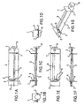
- FIG. 1A there is shown the bottom view of a first embodiment of a ventilation controlling apparatus 1 with two first doors 2, one second door 3 and a cam 4 attached to the first shaft 5 which the first doors 2 are also attached to.
- a pin 6 is attached to the second door 3 and engaged in the cam 4.
- the air passages (not shown) sealable by the doors 2, 3 are separated by partition walls 7 where a second shaft 8 (only shown in the top view in FIG. 1E and the perspective view in FIG. 1 G) moulded in one piece with the second door 3 has its bearings.
- the first shaft 5 is turned by means of the drive element 9 to an angle which causes the first doors 2 attached to that first shaft 5 to take a so called door stop position, meaning they are aligned horizontally where they seal tight their respective air passages (not shown), which are designed accordingly.
- FIG. 1B and 1D which are side views of the ventilation controlling apparatus 1 and FIG. 1C and 1F which are front and back view, respectively thereof.
- FIG. 1G which is a perspective view of the ventilation controlling apparatus 1, is shown that the cam 4 is designed to hold the pin 6 in a position in this state where it keeps the second door 3 closed and aligned horizontally, too.
- the first doors 2 supply side window demisting outlets of a motor vehicle with an air flow.
- the second door 3 feeds the defrost windshield outlet.
- FIG. 2A to 2G show the same views as in FIG. 1A to 1G but with that different angle.
- the predefinition for a is achieved by an appropriate design of the cam 4.
- the first shaft 5 attached to the drive element 9 and first doors 2 take a position partially opening the first doors 2 and thus allowing an air flow to the side window demist outlets. This becomes particularly clear when regarding FIG. 2B, 2D and 2G .
- the second door 3 is kept close because the cam 4 is designed to keep the pin 6 in the respective position up to this predefined aperture angle ⁇ , which is best shown in FIG. 2G .
- the drive element 9 When the operator selects e.g. defrost mode, the drive element 9 is turned to an angle beyond that predefined aperture angle ⁇ as shown in FIG. 3A to 3G , which again show the same views of the ventilation controlling apparatus as in FIG. 1A to 1G but that angle being bigger than ⁇ .
- the first doors 2 are opened wider than in FIG. 2A to 2G and the cam 4 pushes the pin 6 and thus causes the second door 3 to open, too.
- the first shaft 5 has its bearings in the outboard walls of the casing (not shown).
- the shafts 5, 8 are both one-piece, but they could alternatively be split so their respective doors 2, 3 would be attached to two sections of a shaft 5, 8 interrupted in the region of the door 2, 3, so the door 2, 3 would have to perform the task of the shaft 5, 8 here, transmitting torque for instance.
- the second shaft 8 is made in one piece with the second door 3 and the pin 6, they could be separate parts, too. The same applies to the first shaft 5, the first doors 2, the cam 4 and the drive element 9 attached thereon.
- FIG. 4A shows a perspective view of an embodiment of a ventilation controlling apparatus 1 according to the invention.
- Two second doors 3 are cast in one piece with the sections of a second shaft 8 which has its bearings in the partition walls 7 between the second and the first air passages (not shown) and a lever 10 with a pin 6 on one end of the second shaft 8 outside one of these partition walls 7.
- Two first doors 2 are attached to a first shaft 5 which has its bearings in the outboard walls of the casing (not shown) and a drive element 9 with an incorporated cam 4 at one end which the pin 6 is engaged with, best shown in FIG. 4B , which is a perspective view from another point of view.
- the drive element 9 can be a gear.
- the first shaft 5 is turned by means of the drive element 9 to an angle which causes the first doors 2 to take a horizontal door stop position where they seal tight their respective air passages (not shown).
- the cam 4 is designed to hold the pin 6 in a position in this state where it keeps the second doors 3 closed too.
- the first doors 2 supply the side window demisting outlets of a motor vehicle with an air flow.
- the second doors 1 feeds the defrost windshield outlet. In the condition described here and shown in FIG. 4A and 4B neither one of these outlets is given an air flow.
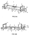
- FIG. 5A and 5B show the ventilation controlling apparatus from the same points of view as in FIG. 4A and 4B but with that different angle.
- the second doors 3 are kept close because the cam 4 is designed to keep the pin 6 in the respective position up to this predefined aperture angle ⁇ see FIG. 5B .
- FIG. 6A and 6B show the ventilation controlling apparatus from the same points of view as in FIG. 4A and 4B but with an angle bigger than the predefined aperture angle ⁇ .
- the first doors 2 are opened wider than in FIG. 5A and 5B and the cam 4 pushes the pin 6 and thus causes the second doors 3 to open, too.
- FIG. 7 shows an essential section of an alternative embodiment of a ventilation controlling apparatus 1 according to the invention with a first shaft 5 arranged coaxially inside a second shaft 8 both engaged with a loaded spring 11 by appropriate tappets 12.1 and 12.2.
- the loaded spring has to have a prestressing that causes the second door (not shown) attached to the second shaft 8 to remain in its door stop position when the first door (not shown) is opened up to the predefined aperture angle ⁇ .
- ⁇ is predefined by the prestress of that loaded spring 11, so the loaded spring is relaxed when the angle of the first door is equal to the predefined aperture angle ⁇ .
Landscapes
- Physics & Mathematics (AREA)
- Thermal Sciences (AREA)
- Engineering & Computer Science (AREA)
- Mechanical Engineering (AREA)
- Air-Conditioning For Vehicles (AREA)
Description
- The present invention relates to a ventilation controlling apparatus and a method for controlling ventilation, particularly for feeding defrost and side window demist outlets in motor vehicles.
- In motor vehicles at moderate outside temperatures (up to 25 °C) passengers usually prefer using the bi-level ventilation mode of a heating, ventilation and air conditioning (HVAC) unit. In this mode vent and floor outlets are at least partially open. When air humidity is high as it tends to be the case the more passengers are inside the side windows are prone to fog up. To keep passengers comfortable in this situation the side windows demist outlets have to be open while the defrost outlets remain closed. Otherwise there could emerge a fogged up spot on the outside of the windshield.
- There are different approaches known for solving this problem. One is the usage of a film door inside the ventilation controlling apparatus as in
US 2002/0197951 A1 . A film door is a film which is moved by two coils, one of them spring loaded. The film has openings stamped out such that the cross sectional open area allows for air to flow through. A ventilation controlling apparatus with such a film door can easily be designed so it solves the aforesaid problem. The disadvantage is its need for space in order to package the two coils as well as the challenge to seal the moving film reliably. - Furthermore the sealing can lead to a wiping or scratching noise during operation which is annoying for the passengers.
- Another approach as in
DE 197 57 280 A1 uses moving doors or butterfly valves equipped with sealing foam wiping on a surface and thus keeping air from flowing to the defrost outlet while the synchronously turned door for the side window demist outlet is already open in this mode. However the wiping or scratching noise problem applies to this solution, too. -
EP 1024041 A1 describes an apparatus according to the preamble ofclaim 1. - It is accordingly an object of the invention to provide an improved ventilation controlling apparatus and a method for controlling ventilation to allow for providing an air flow to a side window demist outlet in bi-level mode while the defrost outlet is kept close.
- With the foregoing and other objects in view there is provided, in accordance with the invention a ventilation controlling apparatus, according to
claim 1. - The predefinition of the predefined aperture angle is achieved by an appropriate design of said mechanical link. Each shaft can be one-piece or split so its respective door is attached to two of its sections interrupted in the region of the door, so the door has to perform the task of the shaft here. Furthermore a shaft can be made in one piece with its respective door especially if they are made of a mouldable or castable material like metal or plastics. In the same way it is possible to make the drive element in one piece with the first shaft. Alternatively shafts, doors and drive element can be single parts, too.
- In other words, when the first door is in its door stop position the second will be, too. The second door will stay so, as long as the first door is turned by means of the drive element between its door stop position and a predefined aperture angle. As soon as the first door is moved beyond that predefined aperture angle the second door will open, too. When feeding a vehicles side window demist outlets with the air flow from the first door and its windshield defrost outlet with that from the second one and turning the drive element to said predefined aperture angle by selecting bi-level mode, the side window demist outlets are given an air flow while the windshield defrost door is not thus avoiding the side windows to fog up and the windshield to get fogged up spots on its outside.
- According to another feature of the invention, the drive element is a gear in order to ease setting its angle.
- According to yet another feature of the invention, the mechanical link comprises a cam and a pin engaged in the cam so turning of the first shaft or the attached drive element causes the second shaft to turn in a way predefined by the cam track. A cam is one of the easiest ways to achieve this behaviour. The cam can be attached to the first shaft, to the drive element or to one of the first doors for this purpose and can also be made in one piece with the part it is attached to or incorporated in the drive element. The pin can be attached to one of the second doors or to a lever again attached to the second shaft. Again it is possible to make the pin in one piece with the part it is attached to and so it is for the lever. Alternatively cam, pin and lever can be single parts, too.
- In an alternative embodiment of the invention, the second shaft or a part of it is arranged coaxially inside a hollow section of the first one or vice versa. The mechanical link comprises a loaded spring engaged with both shafts in this case. This way the ventilation controlling apparatus can be built compactly.
- According to a preferred feature of the invention, the shafts parallel each other, which save some extra space.
- According to the invention, the ventilation controlling apparatus comprises two first air passages and two second air passages with their respective doors separated by partition walls from each other, wherein the two first doors are attached to a common first shaft and the two second doors to a common second shaft, so they turn synchronously.
- According to another feature of the invention, the two second air passages are arranged adjacently to each other in a central region of the casing and the two first air passages beside them adjacently to one second air passage and to one outboard wall of the casing each, so the apparatus is fit for providing an air flow to two or more central outlets by the second air passages and one lateral outlet on both sides by the first ones.
- According to yet another feature of the invention, the first shaft has its bearings in two outboard walls of the casing and the second shaft in two partition walls between first and second air passages.
- The preferred use of the ventilation controlling apparatus is with a motor vehicle, wherein the first air passages feed the side window demist outlets and the second air passages feed the defrost windshield outlet.
- The predefined aperture angle is preferably within a range of 5° to 60°, particularly 10° to 40°.
- In a preferred embodiment of the invention, the predefined angle equals 18° as required by some car manufacturers' specifications.
- The angle of the drive element and thus the first shaft is preferably controlled by the ventilation mode selected by the vehicles operator so that the first door is turned to its predefined aperture angle when bi-level mode is selected. When vent mode is selected, the first door is turned to its door stop position to keep air from flowing to the side window demist outlets and thus the first door remains closed, too.
- Other features which are considered as characteristic for the invention are set forth in the appended claims.
- Although the invention is illustrated and described herein as embodied in a ventilation controlling apparatus, it is nevertheless not intended to be limited to the details shown, since various modifications and structural changes may be made therein without departing from the scope and range of equivalents of the claims.
- The construction and method of operation of the invention, however, together with additional objects and advantages thereof will be best understood from the following description of specific embodiments when read in connection with the accompanying drawings.
-
- FIG. 1A
- is a bottom view of a first embodiment of a ventilation controlling apparatus with two first doors, one second door, a cam attached to the first shaft and a pin attached to the second door and engaged in the cam in a state with all doors closed;
- FIG. 1B
- is a side view of the embodiment of a ventilation controlling apparatus according to
FIG. 1A ; - FIG. 1C
- is a front view of the embodiment of a ventilation controlling apparatus according to
FIG. 1A ; - FIG. 1D
- is another side view of the embodiment of a ventilation controlling apparatus according to
FIG. 1A ; - FIG. 1E
- is a top view of the embodiment of a ventilation controlling apparatus according to
FIG. 1A ; - FIG. 1 F
- is a back view of the embodiment of a ventilation controlling apparatus according to
FIG. 1A ; - FIG. 1G
- is a perspective view of the embodiment of a ventilation controlling apparatus according to
FIG. 1A ; - FIG. 2A
- is a bottom view of the embodiment of a ventilation controlling apparatus according to
FIG. 1A in another state with the first doors partially open and the second door closed; - FIG. 2B
- is a side view of the embodiment of a ventilation controlling apparatus according to
FIG. 2A ; - FIG. 2C
- is a front view of the embodiment of a ventilation controlling apparatus according to
FIG. 2A ; - FIG. 2D
- is another side view of the embodiment of a ventilation controlling apparatus according to
FIG. 2A ; - FIG. 2E
- is a top view of the embodiment of a ventilation controlling apparatus according to
FIG. 2A ; - FIG. 2F
- is a back view of the embodiment of a ventilation controlling apparatus according to
FIG. 2A ; - FIG. 2G
- is a perspective view of the embodiment of a ventilation controlling apparatus according to
FIG. 2A ; - FIG. 3A
- is a bottom view of the embodiment of a ventilation controlling apparatus according to
FIG. 1A in yet another state with all doors open; - FIG. 3B
- is a side view of the embodiment of a ventilation controlling apparatus according to
FIG. 3A ; - FIG. 3C
- is a front view of the embodiment of a ventilation controlling apparatus according to
FIG. 3A ; - FIG. 3D
- is another side view of the embodiment of a ventilation controlling apparatus according to
FIG. 3A ; - FIG. 3E
- is a top view of the embodiment of a ventilation controlling apparatus according to
FIG. 3A ; - FIG. 3F
- is a back view of the embodiment of a ventilation controlling apparatus according to
FIG. 3A ; - FIG. 3G
- is a perspective view of the embodiment of a ventilation controlling apparatus according to
FIG. 3A ; - FIG. 4A
- is a perspective view of an embodiment of a ventilation controlling apparatus according to the invention with two first doors, two second doors, a cam attached to the drive element, a lever attached to the second shaft with an attached pin engaged in the cam in a state with all doors closed;
- FIG. 4B
- is another perspective view of the embodiment of a ventilation controlling apparatus according to
FIG. 4A ; - FIG. 5A
- is a perspective view of the embodiment of a ventilation controlling apparatus according to
FIG. 4A in a state with the first doors partially open and the second doors closed; - FIG. 5B
- is another perspective view of the embodiment of a ventilation controlling apparatus according to
FIG. 5A ; - FIG. 6A
- is a perspective view of the embodiment of a ventilation controlling apparatus according to
FIG. 4A in a state with all doors open; - FIG. 6B
- is another perspective view of the embodiment of a ventilation controlling apparatus according to
FIG. 6A and - FIG. 7
- is a perspective view of a cut-out of an alternative embodiment of a ventilation controlling apparatus with a first shaft arranged inside a second shaft, both engaged with a loaded spring.
- Referring now to the figures of the drawings in detail and first, particularly, to
FIG. 1A thereof, there is shown the bottom view of a first embodiment of aventilation controlling apparatus 1 with twofirst doors 2, onesecond door 3 and acam 4 attached to thefirst shaft 5 which thefirst doors 2 are also attached to. Apin 6 is attached to thesecond door 3 and engaged in thecam 4. The air passages (not shown) sealable by thedoors partition walls 7 where a second shaft 8 (only shown in the top view inFIG. 1E and the perspective view inFIG. 1 G) moulded in one piece with thesecond door 3 has its bearings. - The
first shaft 5 is turned by means of thedrive element 9 to an angle which causes thefirst doors 2 attached to thatfirst shaft 5 to take a so called door stop position, meaning they are aligned horizontally where they seal tight their respective air passages (not shown), which are designed accordingly. This becomes clear when regardingFIG. 1B and 1D , which are side views of theventilation controlling apparatus 1 andFIG. 1C and 1F which are front and back view, respectively thereof. - In
FIG. 1G , which is a perspective view of theventilation controlling apparatus 1, is shown that thecam 4 is designed to hold thepin 6 in a position in this state where it keeps thesecond door 3 closed and aligned horizontally, too. Thefirst doors 2 supply side window demisting outlets of a motor vehicle with an air flow. Thesecond door 3 feeds the defrost windshield outlet. - In the condition described here and shown in
FIG 1A to 1G neither one of these outlets is given an air flow, as it is required when a vehicles operator selects e.g. vent mode. So there has to be a means for setting an angle of thedrive element 9, which can be a gear, for instance, according to the ventilation mode selected. - When the operator selects bi-level mode and thus causes the
drive element 9 to be turned to a predefined aperture angle α, preferably within a range of 5° to 60°, e.g. 18°, as shown inFIG. 2A to 2G , which show the same views as inFIG. 1A to 1G but with that different angle. The predefinition for a is achieved by an appropriate design of thecam 4. Thefirst shaft 5 attached to thedrive element 9 andfirst doors 2 take a position partially opening thefirst doors 2 and thus allowing an air flow to the side window demist outlets. This becomes particularly clear when regardingFIG. 2B, 2D and 2G . Thesecond door 3 is kept close because thecam 4 is designed to keep thepin 6 in the respective position up to this predefined aperture angle α, which is best shown inFIG. 2G . - When the operator selects e.g. defrost mode, the
drive element 9 is turned to an angle beyond that predefined aperture angle α as shown inFIG. 3A to 3G , which again show the same views of the ventilation controlling apparatus as inFIG. 1A to 1G but that angle being bigger than α. Thefirst doors 2 are opened wider than inFIG. 2A to 2G and thecam 4 pushes thepin 6 and thus causes thesecond door 3 to open, too. - The
first shaft 5 has its bearings in the outboard walls of the casing (not shown). In this embodiment theshafts respective doors shaft door door shaft second shaft 8 is made in one piece with thesecond door 3 and thepin 6, they could be separate parts, too. The same applies to thefirst shaft 5, thefirst doors 2, thecam 4 and thedrive element 9 attached thereon. -
FIG. 4A shows a perspective view of an embodiment of aventilation controlling apparatus 1 according to the invention. Twosecond doors 3 are cast in one piece with the sections of asecond shaft 8 which has its bearings in thepartition walls 7 between the second and the first air passages (not shown) and alever 10 with apin 6 on one end of thesecond shaft 8 outside one of thesepartition walls 7. Twofirst doors 2 are attached to afirst shaft 5 which has its bearings in the outboard walls of the casing (not shown) and adrive element 9 with an incorporatedcam 4 at one end which thepin 6 is engaged with, best shown inFIG. 4B , which is a perspective view from another point of view. - The
drive element 9 can be a gear. In the condition shown here, i.e. when vent mode is selected by the vehicles operator, thefirst shaft 5 is turned by means of thedrive element 9 to an angle which causes thefirst doors 2 to take a horizontal door stop position where they seal tight their respective air passages (not shown). Thecam 4 is designed to hold thepin 6 in a position in this state where it keeps thesecond doors 3 closed too. Thefirst doors 2 supply the side window demisting outlets of a motor vehicle with an air flow. Thesecond doors 1 feeds the defrost windshield outlet. In the condition described here and shown inFIG. 4A and 4B neither one of these outlets is given an air flow. - When the operator selects bi-level mode and thus causes the
drive element 9 to be turned to a predefined aperture angle α, e.g. 18°, as shown inFIG. 5A the attachedfirst shaft 5 andfirst doors 2 will take a position partially opening thefirst doors 2 and thus allowing an air flow to the side window demist outlets.FIG. 5A and 5B show the ventilation controlling apparatus from the same points of view as inFIG. 4A and 4B but with that different angle. Thesecond doors 3 are kept close because thecam 4 is designed to keep thepin 6 in the respective position up to this predefined aperture angle α seeFIG. 5B . - When the operator selects e.g. defrost mode, the
drive element 7 is turned to an angle beyond that predefined aperture angle α as shown inFIG. 6A and 6B . These figures show the ventilation controlling apparatus from the same points of view as inFIG. 4A and 4B but with an angle bigger than the predefined aperture angle α. Thefirst doors 2 are opened wider than inFIG. 5A and 5B and thecam 4 pushes thepin 6 and thus causes thesecond doors 3 to open, too. -
FIG. 7 shows an essential section of an alternative embodiment of aventilation controlling apparatus 1 according to the invention with afirst shaft 5 arranged coaxially inside asecond shaft 8 both engaged with a loadedspring 11 by appropriate tappets 12.1 and 12.2. The loaded spring has to have a prestressing that causes the second door (not shown) attached to thesecond shaft 8 to remain in its door stop position when the first door (not shown) is opened up to the predefined aperture angle α. In other words α is predefined by the prestress of that loadedspring 11, so the loaded spring is relaxed when the angle of the first door is equal to the predefined aperture angle α. -
- 1
- ventilation controlling apparatus
- 2
- first door
- 3
- second door
- 4
- cam
- 5
- first shaft
- 6
- pin
- 7
- partition wall
- 8
- second shaft
- 9
- drive element
- 10
- lever
- 11
- loaded spring
- 12
- tappet
- α
- predefined aperture angle
Claims (14)
- A ventilation controlling apparatus (1), comprising:- a casing for forming at least one sealable first air passage and at least one sealable second air passage, said air passages separated from each other by partition walls (7);- each of said first air passages sealable by turning one respective first door (2) each attached to a pivoted first shaft (5) to a respective door stop position;- each of said second air passages sealable by turning one respective second door (3) each attached to a pivoted second shaft (8) to a respective door stop position;- a drive element (9) attached to said first shaft (5),- a mechanical link causing the angle of said second shaft (8) to be a function of the angle of said first shaft (5) in a way that said second door (3) remains in its respective door stop position as long as said first door (2) has an angle ranging from its respective door stop position to a predefined aperture angle (α) and that said second door (3) opens when said first door (2) has an angle exceeding said predefined aperture angle (α),characterized by comprising two of said first air passages with one respective first door (2) each and two of said second air passages with one respective second door (3) each separated by partition wall (7), all of said first doors (2) attached to said first shaft (5) and all of said second doors (3) attached to said second shaft (8).
- The ventilation controlling apparatus (1) according to claim 1, wherein said drive element (9) is a gear.
- The ventilation controlling apparatus (1) according to claim 1 or 2, wherein said mechanical link at least comprises a cam (4) and a pin (6) engaged in said cam.
- The ventilation controlling apparatus (1) according to claim 3, wherein said cam (4) is attached to said first shaft (5).
- The ventilation controlling apparatus (1) according to claim 3, wherein said cam (4) is attached to any one of said first doors (2).
- The ventilation controlling apparatus (1) according to claim 3, wherein said mechanical link additionally comprises a lever (10) attached to said second shaft (8), said pin (6) attached to said lever.
- The ventilation controlling apparatus (1) according to at least one of the claims 1 to 6, wherein said first shaft (5) is at least partially hollow and said second shaft (8) at least partially arranged coaxially inside of said first shaft's hollow section and the mechanical link comprises a loaded spring (11) engaged with said first shaft (5) and said second shaft (8).
- The ventilation controlling apparatus (1) according to at least one of the claims 1 to 6, wherein said second shaft (8) is at least partially hollow and said first shaft (5) at least partially arranged coaxially inside of said second shaft's hollow section and the mechanical link comprises a loaded spring (11) engaged with said first shaft (5) and said second shaft (8).
- The ventilation controlling apparatus (1) according to claim 1, wherein said two second air passages are arranged adjacently to each other in a central region of said casing and each of said two first air passages is arranged adjacently to one of said second air passages and one outboard wall of said casing.
- The ventilation controlling apparatus according to at least one of the claims 1 to 9, wherein said first shaft (5) has its bearings at least in two outboard walls of said casing and said second shaft (8) has its bearings at least in two partition walls (7) each of them between one of said first air passages and one of said second air passages.
- Use of the ventilation controlling apparatus (1) according to at least one of the claims 1 to 12 in a motor vehicle, wherein said first air passage provides at least one side window demist air outlet with an air flow and said second air passage provides at least one defrost windshield outlet with an air flow.
- A method for controlling ventilation with a ventilation controlling apparatus (1) according to at least one of the claims 1 to 10, wherein turning of said drive element (9) sets the angle of said first door (2) and by means of said mechanical link the angle of said second door (3) whose angle is a function of said first doors angle, said function defined by said mechanical link causing said second door (3) to be in its respective door stop position as long as said first doors position is in a range from its respective door stop position to said predefined aperture angle (α) and furthermore causing said second door (3) to open when said first door (2) has an angle exceeding said predefined aperture angle (α).
- The method according to claim 12, wherein said predefined aperture angle (α) is within a range of 5° to 60°.
- The method according to claim 12 or 13 applied in a motor vehicle, wherein the air flow from said first air passage feeds at least one side window demist outlet, the airflow from said second air passage feeds at least one defrost outlet and the angle of said drive element (9) and thus said first door (2) is controlled by a ventilation mode selected by a motor vehicles operator so that said first door (2) is turned to said predefined angle when bi-level mode is selected.
Applications Claiming Priority (2)
| Application Number | Priority Date | Filing Date | Title |
|---|---|---|---|
| US79872006P | 2006-05-09 | 2006-05-09 | |
| PCT/US2007/010901 WO2007133486A1 (en) | 2006-05-09 | 2007-05-04 | Ventilation controlling apparatus and method for controlling ventilation in motor vehicles |
Publications (2)
| Publication Number | Publication Date |
|---|---|
| EP2018284A1 EP2018284A1 (en) | 2009-01-28 |
| EP2018284B1 true EP2018284B1 (en) | 2012-09-26 |
Family
ID=38566959
Family Applications (1)
| Application Number | Title | Priority Date | Filing Date |
|---|---|---|---|
| EP07776778A Not-in-force EP2018284B1 (en) | 2006-05-09 | 2007-05-04 | Ventilation controlling apparatus and method for controlling ventilation in motor vehicles |
Country Status (3)
| Country | Link |
|---|---|
| US (1) | US9566844B2 (en) |
| EP (1) | EP2018284B1 (en) |
| WO (1) | WO2007133486A1 (en) |
Families Citing this family (12)
| Publication number | Priority date | Publication date | Assignee | Title |
|---|---|---|---|---|
| US9610823B2 (en) * | 2008-09-25 | 2017-04-04 | Mahle International Gmbh | Vehicle HVAC temperature control system |
| JP5627297B2 (en) * | 2010-05-31 | 2014-11-19 | 三菱重工業株式会社 | Air conditioner for vehicles |
| DE102011002606B4 (en) * | 2011-01-13 | 2022-12-15 | Ford Global Technologies, Llc | Ventilation control device for a heating and/or air conditioning system of a vehicle |
| KR101305822B1 (en) * | 2011-10-17 | 2013-09-06 | 현대자동차주식회사 | Air conditioning system for vehicle |
| DK178369B1 (en) * | 2012-12-05 | 2016-01-18 | Climawin Techniq Aps | A ventilation device, a window comprising the ventilation device and a method for operating the ventilation device. |
| US10052934B2 (en) * | 2013-05-10 | 2018-08-21 | Denso International America, Inc. | Convex grid shape to reduce turbulence under rotary door |
| US20170297413A9 (en) * | 2015-03-25 | 2017-10-19 | Denso International America, Inc. | Automotive hvac system |
| DE102015108316A1 (en) * | 2015-05-27 | 2016-12-01 | Valeo Klimasysteme Gmbh | Module for heating, ventilation and / or air conditioning of a passenger compartment of a motor vehicle |
| US10632819B2 (en) | 2016-03-31 | 2020-04-28 | Denso International America, Inc. | Demist control for HVAC |
| KR102635116B1 (en) * | 2018-03-07 | 2024-02-08 | 한온시스템 주식회사 | Air conditioner for vehicle |
| US11331976B2 (en) * | 2019-05-17 | 2022-05-17 | Marelli Cabin Comfort Usa, Inc. | HVAC sealing surface with noise reduction configuration |
| DE102020108717A1 (en) * | 2020-03-30 | 2021-09-30 | Kautex Textron Gmbh & Co. Kg | Valve device for controlling at least two air currents and a roof system to be emitted into a motor vehicle interior via a roof system |
Family Cites Families (18)
| Publication number | Priority date | Publication date | Assignee | Title |
|---|---|---|---|---|
| DE1204899B (en) | 1961-05-17 | 1965-11-11 | Sueddeutsche Kuehler Behr | throttle |
| FR2063253A5 (en) * | 1969-09-08 | 1971-07-09 | Peugeot & Renault | |
| US3635245A (en) * | 1969-10-06 | 1972-01-18 | John L Canfield | Air control device |
| US3911953A (en) * | 1974-07-05 | 1975-10-14 | Northwest Eng Service | Three-plenum mixing dampers |
| US3994335A (en) * | 1975-03-06 | 1976-11-30 | Robertshaw Controls Company | Multizone air conditioning system |
| JPS6228492Y2 (en) * | 1981-04-17 | 1987-07-22 | ||
| JPS61229609A (en) | 1985-04-02 | 1986-10-13 | Nissan Motor Co Ltd | Air-conditioning device |
| FR2698589B1 (en) * | 1992-12-02 | 1995-02-17 | Valeo Thermique Habitacle | Heating-ventilation and / or air conditioning device for the passenger compartment of a motor vehicle. |
| DE19505336A1 (en) * | 1995-02-17 | 1996-08-22 | Behr Gmbh & Co | Heating and / or air conditioning system for a motor vehicle |
| JP3758262B2 (en) | 1996-12-25 | 2006-03-22 | 株式会社デンソー | Air conditioner |
| DE19739578C2 (en) * | 1997-09-10 | 2000-03-02 | Behr Gmbh & Co | Heating or air conditioning for a motor vehicle |
| US6045444A (en) * | 1998-08-28 | 2000-04-04 | General Motors Corporation | Compact automotive air conditioning module |
| GB2346199A (en) | 1999-01-28 | 2000-08-02 | Delphi Tech Inc | Flap valve mechanism and air treatment system |
| JP4253960B2 (en) * | 1999-11-18 | 2009-04-15 | 株式会社デンソー | Air conditioner for vehicles |
| US6536474B2 (en) * | 2000-03-13 | 2003-03-25 | Calsonic Kansei Corporation | Air conditioner unit for vehicle |
| JP3695390B2 (en) * | 2001-06-22 | 2005-09-14 | 株式会社デンソー | Air passage opening and closing device and vehicle air conditioner |
| DE602005017751D1 (en) * | 2005-05-25 | 2009-12-31 | Valeo Autoklimatizace S R O | Air distribution device with rotary valves with interdependent rotational movements |
| JP5772775B2 (en) * | 2012-09-20 | 2015-09-02 | 豊田合成株式会社 | Air conditioning register |
-
2007
- 2007-05-04 US US12/299,703 patent/US9566844B2/en not_active Expired - Fee Related
- 2007-05-04 WO PCT/US2007/010901 patent/WO2007133486A1/en not_active Ceased
- 2007-05-04 EP EP07776778A patent/EP2018284B1/en not_active Not-in-force
Also Published As
| Publication number | Publication date |
|---|---|
| US20090305623A1 (en) | 2009-12-10 |
| WO2007133486A1 (en) | 2007-11-22 |
| EP2018284A1 (en) | 2009-01-28 |
| US9566844B2 (en) | 2017-02-14 |
Similar Documents
| Publication | Publication Date | Title |
|---|---|---|
| US9566844B2 (en) | Ventilation controlling apparatus and method for controlling ventilation in motor vehicles | |
| US8113268B2 (en) | Sequential valve member driving mechanism for an HVAC system | |
| US6347988B1 (en) | Slide door unit for use in automotive air conditioner | |
| JPS633523Y2 (en) | ||
| JP4253960B2 (en) | Air conditioner for vehicles | |
| EP1614560A3 (en) | Automotive air conditioning device | |
| US20180170149A1 (en) | Air register with hybrid door closure | |
| US20180141404A1 (en) | Rear Seat Air Regulating Device for HVAC Module | |
| US7775451B2 (en) | Variable flow mixing valve | |
| US8887797B2 (en) | Air-conditioner for vehicle | |
| EP1630015B1 (en) | Valve driving mechanism for an HVAC system | |
| KR20120088114A (en) | Air conditioner for vehicle | |
| US20060151162A1 (en) | Louvre for an air-conduction housing of a vehicle air-conditioning system | |
| EP1389542B1 (en) | Heating, ventilation, and air conditioning system having improved air warm-up | |
| US6296564B1 (en) | Heater or air conditioner for vehicles | |
| WO2007061039A1 (en) | Air conditioner for vehicle | |
| JP4364581B2 (en) | Air guide structure for passenger cars | |
| US20100126072A1 (en) | Door Operating Device of Air Conditioner for Automobile | |
| JP2003089314A (en) | Automotive air conditioners | |
| JP2008183959A (en) | Vehicular air-conditioner | |
| US7470177B2 (en) | Device for control of air flow rates to the instrument panel air outlets of a vehicle heating or air conditioning unit | |
| JP4487436B2 (en) | Link plate structure of air conditioner | |
| JP3827855B2 (en) | Air conditioner for automobile | |
| KR100578417B1 (en) | Driving device of vehicle air conditioner door | |
| KR100531638B1 (en) | Dual actuator device for minimizing temperature device and actuator included in the device |
Legal Events
| Date | Code | Title | Description |
|---|---|---|---|
| PUAI | Public reference made under article 153(3) epc to a published international application that has entered the european phase |
Free format text: ORIGINAL CODE: 0009012 |
|
| 17P | Request for examination filed |
Effective date: 20081209 |
|
| AK | Designated contracting states |
Kind code of ref document: A1 Designated state(s): AT BE BG CH CY CZ DE DK EE ES FI FR GB GR HU IE IS IT LI LT LU LV MC MT NL PL PT RO SE SI SK TR |
|
| AX | Request for extension of the european patent |
Extension state: AL BA HR MK RS |
|
| 17Q | First examination report despatched |
Effective date: 20100504 |
|
| GRAP | Despatch of communication of intention to grant a patent |
Free format text: ORIGINAL CODE: EPIDOSNIGR1 |
|
| DAX | Request for extension of the european patent (deleted) | ||
| GRAS | Grant fee paid |
Free format text: ORIGINAL CODE: EPIDOSNIGR3 |
|
| GRAA | (expected) grant |
Free format text: ORIGINAL CODE: 0009210 |
|
| AK | Designated contracting states |
Kind code of ref document: B1 Designated state(s): AT BE BG CH CY CZ DE DK EE ES FI FR GB GR HU IE IS IT LI LT LU LV MC MT NL PL PT RO SE SI SK TR |
|
| REG | Reference to a national code |
Ref country code: GB Ref legal event code: FG4D |
|
| REG | Reference to a national code |
Ref country code: CH Ref legal event code: EP |
|
| REG | Reference to a national code |
Ref country code: AT Ref legal event code: REF Ref document number: 576860 Country of ref document: AT Kind code of ref document: T Effective date: 20121015 |
|
| REG | Reference to a national code |
Ref country code: IE Ref legal event code: FG4D |
|
| REG | Reference to a national code |
Ref country code: DE Ref legal event code: R096 Ref document number: 602007025744 Country of ref document: DE Effective date: 20121122 |
|
| PG25 | Lapsed in a contracting state [announced via postgrant information from national office to epo] |
Ref country code: LT Free format text: LAPSE BECAUSE OF FAILURE TO SUBMIT A TRANSLATION OF THE DESCRIPTION OR TO PAY THE FEE WITHIN THE PRESCRIBED TIME-LIMIT Effective date: 20120926 Ref country code: FI Free format text: LAPSE BECAUSE OF FAILURE TO SUBMIT A TRANSLATION OF THE DESCRIPTION OR TO PAY THE FEE WITHIN THE PRESCRIBED TIME-LIMIT Effective date: 20120926 |
|
| REG | Reference to a national code |
Ref country code: AT Ref legal event code: MK05 Ref document number: 576860 Country of ref document: AT Kind code of ref document: T Effective date: 20120926 |
|
| REG | Reference to a national code |
Ref country code: LT Ref legal event code: MG4D Effective date: 20120926 |
|
| REG | Reference to a national code |
Ref country code: NL Ref legal event code: VDEP Effective date: 20120926 |
|
| PG25 | Lapsed in a contracting state [announced via postgrant information from national office to epo] |
Ref country code: LV Free format text: LAPSE BECAUSE OF FAILURE TO SUBMIT A TRANSLATION OF THE DESCRIPTION OR TO PAY THE FEE WITHIN THE PRESCRIBED TIME-LIMIT Effective date: 20120926 Ref country code: GR Free format text: LAPSE BECAUSE OF FAILURE TO SUBMIT A TRANSLATION OF THE DESCRIPTION OR TO PAY THE FEE WITHIN THE PRESCRIBED TIME-LIMIT Effective date: 20121227 Ref country code: SI Free format text: LAPSE BECAUSE OF FAILURE TO SUBMIT A TRANSLATION OF THE DESCRIPTION OR TO PAY THE FEE WITHIN THE PRESCRIBED TIME-LIMIT Effective date: 20120926 Ref country code: SE Free format text: LAPSE BECAUSE OF FAILURE TO SUBMIT A TRANSLATION OF THE DESCRIPTION OR TO PAY THE FEE WITHIN THE PRESCRIBED TIME-LIMIT Effective date: 20120926 |
|
| PG25 | Lapsed in a contracting state [announced via postgrant information from national office to epo] |
Ref country code: ES Free format text: LAPSE BECAUSE OF FAILURE TO SUBMIT A TRANSLATION OF THE DESCRIPTION OR TO PAY THE FEE WITHIN THE PRESCRIBED TIME-LIMIT Effective date: 20130106 Ref country code: BE Free format text: LAPSE BECAUSE OF FAILURE TO SUBMIT A TRANSLATION OF THE DESCRIPTION OR TO PAY THE FEE WITHIN THE PRESCRIBED TIME-LIMIT Effective date: 20120926 Ref country code: EE Free format text: LAPSE BECAUSE OF FAILURE TO SUBMIT A TRANSLATION OF THE DESCRIPTION OR TO PAY THE FEE WITHIN THE PRESCRIBED TIME-LIMIT Effective date: 20120926 Ref country code: CZ Free format text: LAPSE BECAUSE OF FAILURE TO SUBMIT A TRANSLATION OF THE DESCRIPTION OR TO PAY THE FEE WITHIN THE PRESCRIBED TIME-LIMIT Effective date: 20120926 Ref country code: IS Free format text: LAPSE BECAUSE OF FAILURE TO SUBMIT A TRANSLATION OF THE DESCRIPTION OR TO PAY THE FEE WITHIN THE PRESCRIBED TIME-LIMIT Effective date: 20130126 Ref country code: NL Free format text: LAPSE BECAUSE OF FAILURE TO SUBMIT A TRANSLATION OF THE DESCRIPTION OR TO PAY THE FEE WITHIN THE PRESCRIBED TIME-LIMIT Effective date: 20120926 Ref country code: RO Free format text: LAPSE BECAUSE OF FAILURE TO SUBMIT A TRANSLATION OF THE DESCRIPTION OR TO PAY THE FEE WITHIN THE PRESCRIBED TIME-LIMIT Effective date: 20120926 |
|
| PG25 | Lapsed in a contracting state [announced via postgrant information from national office to epo] |
Ref country code: PL Free format text: LAPSE BECAUSE OF FAILURE TO SUBMIT A TRANSLATION OF THE DESCRIPTION OR TO PAY THE FEE WITHIN THE PRESCRIBED TIME-LIMIT Effective date: 20120926 Ref country code: SK Free format text: LAPSE BECAUSE OF FAILURE TO SUBMIT A TRANSLATION OF THE DESCRIPTION OR TO PAY THE FEE WITHIN THE PRESCRIBED TIME-LIMIT Effective date: 20120926 Ref country code: PT Free format text: LAPSE BECAUSE OF FAILURE TO SUBMIT A TRANSLATION OF THE DESCRIPTION OR TO PAY THE FEE WITHIN THE PRESCRIBED TIME-LIMIT Effective date: 20130128 Ref country code: CY Free format text: LAPSE BECAUSE OF FAILURE TO SUBMIT A TRANSLATION OF THE DESCRIPTION OR TO PAY THE FEE WITHIN THE PRESCRIBED TIME-LIMIT Effective date: 20120926 |
|
| PG25 | Lapsed in a contracting state [announced via postgrant information from national office to epo] |
Ref country code: AT Free format text: LAPSE BECAUSE OF FAILURE TO SUBMIT A TRANSLATION OF THE DESCRIPTION OR TO PAY THE FEE WITHIN THE PRESCRIBED TIME-LIMIT Effective date: 20120926 |
|
| PG25 | Lapsed in a contracting state [announced via postgrant information from national office to epo] |
Ref country code: BG Free format text: LAPSE BECAUSE OF FAILURE TO SUBMIT A TRANSLATION OF THE DESCRIPTION OR TO PAY THE FEE WITHIN THE PRESCRIBED TIME-LIMIT Effective date: 20121226 Ref country code: DK Free format text: LAPSE BECAUSE OF FAILURE TO SUBMIT A TRANSLATION OF THE DESCRIPTION OR TO PAY THE FEE WITHIN THE PRESCRIBED TIME-LIMIT Effective date: 20120926 |
|
| PLBE | No opposition filed within time limit |
Free format text: ORIGINAL CODE: 0009261 |
|
| STAA | Information on the status of an ep patent application or granted ep patent |
Free format text: STATUS: NO OPPOSITION FILED WITHIN TIME LIMIT |
|
| PG25 | Lapsed in a contracting state [announced via postgrant information from national office to epo] |
Ref country code: IT Free format text: LAPSE BECAUSE OF FAILURE TO SUBMIT A TRANSLATION OF THE DESCRIPTION OR TO PAY THE FEE WITHIN THE PRESCRIBED TIME-LIMIT Effective date: 20120926 |
|
| 26N | No opposition filed |
Effective date: 20130627 |
|
| REG | Reference to a national code |
Ref country code: DE Ref legal event code: R097 Ref document number: 602007025744 Country of ref document: DE Effective date: 20130627 |
|
| PG25 | Lapsed in a contracting state [announced via postgrant information from national office to epo] |
Ref country code: MC Free format text: LAPSE BECAUSE OF FAILURE TO SUBMIT A TRANSLATION OF THE DESCRIPTION OR TO PAY THE FEE WITHIN THE PRESCRIBED TIME-LIMIT Effective date: 20120926 |
|
| REG | Reference to a national code |
Ref country code: CH Ref legal event code: PL |
|
| GBPC | Gb: european patent ceased through non-payment of renewal fee |
Effective date: 20130504 |
|
| PG25 | Lapsed in a contracting state [announced via postgrant information from national office to epo] |
Ref country code: LI Free format text: LAPSE BECAUSE OF NON-PAYMENT OF DUE FEES Effective date: 20130531 Ref country code: CH Free format text: LAPSE BECAUSE OF NON-PAYMENT OF DUE FEES Effective date: 20130531 |
|
| REG | Reference to a national code |
Ref country code: IE Ref legal event code: MM4A |
|
| PG25 | Lapsed in a contracting state [announced via postgrant information from national office to epo] |
Ref country code: GB Free format text: LAPSE BECAUSE OF NON-PAYMENT OF DUE FEES Effective date: 20130504 Ref country code: IE Free format text: LAPSE BECAUSE OF NON-PAYMENT OF DUE FEES Effective date: 20130504 |
|
| PG25 | Lapsed in a contracting state [announced via postgrant information from national office to epo] |
Ref country code: MT Free format text: LAPSE BECAUSE OF FAILURE TO SUBMIT A TRANSLATION OF THE DESCRIPTION OR TO PAY THE FEE WITHIN THE PRESCRIBED TIME-LIMIT Effective date: 20120926 |
|
| REG | Reference to a national code |
Ref country code: DE Ref legal event code: R082 Ref document number: 602007025744 Country of ref document: DE Representative=s name: GRAUEL, ANDREAS, DIPL.-PHYS. DR. RER. NAT., DE |
|
| REG | Reference to a national code |
Ref country code: DE Ref legal event code: R081 Ref document number: 602007025744 Country of ref document: DE Owner name: MAHLE BEHR USA INC., TROY, US Free format text: FORMER OWNER: BEHR AMERICA, INC., BEHR GMBH & CO. KG, , US Effective date: 20150331 Ref country code: DE Ref legal event code: R082 Ref document number: 602007025744 Country of ref document: DE Representative=s name: GRAUEL, ANDREAS, DIPL.-PHYS. DR. RER. NAT., DE Effective date: 20150331 Ref country code: DE Ref legal event code: R081 Ref document number: 602007025744 Country of ref document: DE Owner name: MAHLE INTERNATIONAL GMBH, DE Free format text: FORMER OWNER: BEHR AMERICA, INC., BEHR GMBH & CO. KG, , US Effective date: 20150331 Ref country code: DE Ref legal event code: R081 Ref document number: 602007025744 Country of ref document: DE Owner name: MAHLE INTERNATIONAL GMBH, DE Free format text: FORMER OWNERS: BEHR AMERICA, INC., WEBBERVILLE, MICH., US; BEHR GMBH & CO. KG, 70469 STUTTGART, DE Effective date: 20150331 |
|
| PG25 | Lapsed in a contracting state [announced via postgrant information from national office to epo] |
Ref country code: TR Free format text: LAPSE BECAUSE OF FAILURE TO SUBMIT A TRANSLATION OF THE DESCRIPTION OR TO PAY THE FEE WITHIN THE PRESCRIBED TIME-LIMIT Effective date: 20120926 |
|
| REG | Reference to a national code |
Ref country code: DE Ref legal event code: R082 Ref document number: 602007025744 Country of ref document: DE Representative=s name: GRAUEL, ANDREAS, DIPL.-PHYS. DR. RER. NAT., DE Ref country code: DE Ref legal event code: R081 Ref document number: 602007025744 Country of ref document: DE Owner name: MAHLE INTERNATIONAL GMBH, DE Free format text: FORMER OWNER: MAHLE BEHR USA INC., MAHLE INTERNATIONAL GMBH, , US Ref country code: DE Ref legal event code: R081 Ref document number: 602007025744 Country of ref document: DE Owner name: MAHLE INTERNATIONAL GMBH, DE Free format text: FORMER OWNERS: MAHLE BEHR USA INC., TROY, MICH., US; MAHLE INTERNATIONAL GMBH, 70376 STUTTGART, DE |
|
| PG25 | Lapsed in a contracting state [announced via postgrant information from national office to epo] |
Ref country code: LU Free format text: LAPSE BECAUSE OF NON-PAYMENT OF DUE FEES Effective date: 20130504 Ref country code: HU Free format text: LAPSE BECAUSE OF FAILURE TO SUBMIT A TRANSLATION OF THE DESCRIPTION OR TO PAY THE FEE WITHIN THE PRESCRIBED TIME-LIMIT; INVALID AB INITIO Effective date: 20070504 |
|
| REG | Reference to a national code |
Ref country code: FR Ref legal event code: PLFP Year of fee payment: 10 |
|
| REG | Reference to a national code |
Ref country code: FR Ref legal event code: PLFP Year of fee payment: 11 |
|
| REG | Reference to a national code |
Ref country code: FR Ref legal event code: PLFP Year of fee payment: 12 |
|
| PGFP | Annual fee paid to national office [announced via postgrant information from national office to epo] |
Ref country code: DE Payment date: 20190715 Year of fee payment: 13 |
|
| REG | Reference to a national code |
Ref country code: DE Ref legal event code: R119 Ref document number: 602007025744 Country of ref document: DE |
|
| PG25 | Lapsed in a contracting state [announced via postgrant information from national office to epo] |
Ref country code: DE Free format text: LAPSE BECAUSE OF NON-PAYMENT OF DUE FEES Effective date: 20201201 |
|
| PGFP | Annual fee paid to national office [announced via postgrant information from national office to epo] |
Ref country code: FR Payment date: 20230525 Year of fee payment: 17 |
|
| PG25 | Lapsed in a contracting state [announced via postgrant information from national office to epo] |
Ref country code: FR Free format text: LAPSE BECAUSE OF NON-PAYMENT OF DUE FEES Effective date: 20240531 |