EP2018040A1 - Konturierungsverringerung beim Rastern - Google Patents
Konturierungsverringerung beim Rastern Download PDFInfo
- Publication number
- EP2018040A1 EP2018040A1 EP07014205A EP07014205A EP2018040A1 EP 2018040 A1 EP2018040 A1 EP 2018040A1 EP 07014205 A EP07014205 A EP 07014205A EP 07014205 A EP07014205 A EP 07014205A EP 2018040 A1 EP2018040 A1 EP 2018040A1
- Authority
- EP
- European Patent Office
- Prior art keywords
- pixels
- dot
- intensity
- continuous
- halftone
- Prior art date
- Legal status (The legal status is an assumption and is not a legal conclusion. Google has not performed a legal analysis and makes no representation as to the accuracy of the status listed.)
- Withdrawn
Links
Images


Classifications
-
- H—ELECTRICITY
- H04—ELECTRIC COMMUNICATION TECHNIQUE
- H04N—PICTORIAL COMMUNICATION, e.g. TELEVISION
- H04N1/00—Scanning, transmission or reproduction of documents or the like, e.g. facsimile transmission; Details thereof
- H04N1/40—Picture signal circuits
- H04N1/40081—Soft dot halftoning, i.e. producing halftone dots with gradual edges
-
- H—ELECTRICITY
- H04—ELECTRIC COMMUNICATION TECHNIQUE
- H04N—PICTORIAL COMMUNICATION, e.g. TELEVISION
- H04N1/00—Scanning, transmission or reproduction of documents or the like, e.g. facsimile transmission; Details thereof
- H04N1/40—Picture signal circuits
- H04N1/40087—Multi-toning, i.e. converting a continuous-tone signal for reproduction with more than two discrete brightnesses or optical densities, e.g. dots of grey and black inks on white paper
-
- H—ELECTRICITY
- H04—ELECTRIC COMMUNICATION TECHNIQUE
- H04N—PICTORIAL COMMUNICATION, e.g. TELEVISION
- H04N1/00—Scanning, transmission or reproduction of documents or the like, e.g. facsimile transmission; Details thereof
- H04N1/46—Colour picture communication systems
- H04N1/52—Circuits or arrangements for halftone screening
Definitions
- the present invention refers to halftoning techniques and, for example, to halftoning techniques which reduce contouring effects.
- printers for example electrophotographic printers for use in the office or home for printing out images (e.g. photographs) use a process of digital halftoning to convert electronic image data into print instructions sent to a printer in order to print a plurality of small dots onto a printing medium, to create an image on the printing medium.
- halftoning is used for printing images having varying shades of color or gray, such as photographs.
- Halftoning is the transformation of a grayscale or color image to a pattern (screen) of pixels with a limited number of colors (e.g. just black pixels on white background, or spots of the primary colors cyan, magenta and yellow), in order to make it printable.
- printing is a binary process for each point on the paper: either to put toner on a paper or leave the paper uncovered. This would suggest that only binary images could be printed.
- halftoning makes it possible to reproduce so-called continuous-tone images, which are images with different shades of gray or color.
- the halftone process creates dot patterns on a background (e.g. white paper). When viewed from a sufficient distance, the human viewer will be unable to see the dots themselves, because they are too small.
- gray-scale halftoning only black dots are created, whereas in color halftoning dots of the three primary colors of subtractive color mixing, cyan, magenta, yellow (and black) are created and printed on top of each other.
- the printable dots are composed of pixels (an individual spot which may be printed or not), the more pixels that are set, the larger the dots appears to be.
- This type of halftoning is also referred to as AM (amplitude modulation).
- AM-halftoning varies the size of dots, but not their location. Darker areas (shadows) have larger dots and highlight areas have smaller dots.
- FM (frequency modulation) halftoning in which all dots have the same size, but their location is varied. Darker areas have more dots closer together while the lighter areas have fewer dots dispersed farther apart.
- EP 0 892 549 refers to a method and apparatus for reproducing an image with gray level printing.
- the document addresses the problem of contouring effects in halftoning and obtains a smooth shade by building the dots in a line-type structure according to a template.
- Plural dots of size 1 are laid down along lines according to the template.
- the dots are laid down along the lines also according to the arrangement, but all are of size 2.
- the template arrangement for growth is similarly used for growth to successive gray levels. The process continues by building multiple pixel dots at each gray level on top of the line structure so as to produce a more stable line structure.
- a method is provided of transforming continuous-tone values to a halftone representation with halftone dot patterns.
- a dot pattern is composed of dots, and a dot is composed of a plurality of pixels.
- a pixel can be assigned zero intensity, or one out of a set of intermediate intensities or full intensity, wherein the transformation is such that a first continuous-tone value is transformed into a number of pixels of zero intensity, a number of pixels of the one or more intermediate intensities, and a number of pixels of full intensity.
- a second, higher continuous-tone value is transformed into a reduced number of pixels of zero intensity and a correspondingly increased number of pixels with full intensity, while leaving the number of pixels of the one or more intermediate intensities substantially constant.
- a printing system for transforming continuous-tone values to a halftone representation with halftone dot patterns.
- a dot pattern is composed of dots, and a dot is composed of a plurality of pixels.
- a pixel can be assigned zero intensity, or one out of a set of intermediate intensities or full intensity.
- the printing system is programmed to perform the transformation which is such that a first continuous-tone value is transformed into a number of pixels of zero intensity, a number of pixels of the one or more intermediate intensities, and a number of pixels of full intensity.
- a second, higher continuous-tone value is transformed into a reduced number of pixels of zero intensity and a correspondingly increased number of pixels with full intensity, while leaving the number of pixels of the one or more intermediate intensities substantially constant.
- a computer program product which is either in the form of a machine-readable medium with program code stored on it, or in the form of a propagated signal including a representation of program code.
- the program code is arranged to carry out a method, when executed on a computer system, of transforming continuous-tone values to a halftone representation with halftone dot patterns.
- a dot pattern is composed of dots, a dot is composed of a plurality of pixels.
- a pixel can be assigned zero intensity, or one out of a set of intermediate intensities or full intensity.
- the transformation is such that a first continuous-tone value is transformed into a number of pixels of zero intensity, a number of pixels of the one or more intermediate intensities, and a number of pixels of full intensity.
- a second, higher continuous-tone value is transformed into a reduced number of pixels of zero intensity and a correspondingly increased number of pixels with full intensity, while leaving the number of pixels of the one or more intermediate intensities substantially constant.
- Fig. 1 shows an electrophotographic printer. However, before proceeding further with the description of Fig. 1 , a few items of the embodiments will be discussed.
- continuous-tone values are transformed to a halftone representation with halftone dot patterns.
- a dot pattern is composed of dots.
- a dot is composed of a plurality of pixels, wherein a pixel can be assigned zero intensity, or one out of a set of intermediate intensities or full intensity.
- the transformation is such that a first continuous-tone value is transformed into a number of pixels of zero intensity, a number of pixels of the one or more intermediate intensities, and a number of pixels of full intensity.
- a second, higher continuous-tone value is transformed into a reduced number of pixels of zero intensity and a correspondingly increased number of pixels with full intensity, while leaving the number of pixels of the one or more intermediate intensities substantially constant.
- pixel refers to an individual spot which is printed with full intensity, or an intermediate intensity or zero intensity.
- dot refers to an "agglomeration of pixels” which is also referred to as a “cluster”.
- a "halftone dot pattern” is a printable representation of a continuous-tone value and includes dots of varying sizes, so that overall the dots simulate a certain density.
- a particularly useful type of tile/screen is a regular screen, in which all the dots have the same shape.
- the halftone patterns produced by such screens look smooth to the eye because the dot pattern obtained is regular on paper.
- a pixel is printed on paper by removing charges from a photoconductive drum by means of a laser.
- the smallest area of the photoconductor which can be exposed by the laser is a pixel.
- the printer exposes one or several pixels, using different amounts of laser power.
- laser power levels of 0% (no exposure), 33%, 66% and 100% of the nominal power of the laser are used. However, also other values may be used in other embodiments.
- the dots produced by a regular screen will all contain the same exposure.
- the dots could contain a 100%-pixel and a 33%-pixel.
- the percentages are referred to as "exposure levels" and represent the fraction of the nominal laser power used to expose the pixel.
- the dots may be created with a 100% pixel plus a 66% pixel, and on the next level with two 100% pixels.
- the dots at each level are larger, because there is more exposure and the optical density of the print increases.
- increments in density may be dependent on the level of exposure. This means the density increment when going from 33% to 66% may be significantly different from the density increment going from 66% to 100%. These unequal increments in density can be perceived as contouring effects. To overcome this problem, increments exposure of different sorts are added to the clusters so that uniform increments in dot size may be obtained.
- the number of pixels of intermediate intensities is kept constant for representing continuous-tone values of whatever lightness
- the number of pixels of intermediate intensities is kept constant only of continuous-tone values pertaining to shadow areas, while the numbers of pixels with intermediate intensities are varied to obtain regular dot patterns (all dots have the same shape) in highlight areas.
- the term “intensities” may be interpreted as the power levels of a laser of an electrophotographic printer, in other embodiments, the term may refer to the amount of ink provided for printing a pixel in a color inkjet printer.
- the intermediate intensities are 33% and 66% of the full intensity and may refer - in the case of laser printers - to the power levels used to obtain different exposures of a pixel.
- a dot is composed of ten pixels.
- the halftone dot patterns for representing highlight continuous-tone values have regular dot patterns, and the halftone dot patterns representing darker continuous-tone values have irregular dot patterns.
- a dot turn-on is defined by means of a halftone tile indicating the positions of center pixels of dots.
- halftone tiles modified according to a halftone frequency response optimization are put together to form a super-tile to increase periodicity of the halftone dot patterns.
- the halftone tiles for different primary colors are obtained by rotating the tile through an angle.
- the rotation of halftone tiles is performed to avoid undesirable moiré-patterns.
- dot growth is defined by means of tiles containing threshold values which are compared with the continuous-tone values of the image which is to be reproduced. If the value of the image is higher (or lower) than the threshold value, then a pixel of the dot is activated, i.e. ink is printed in that pixel, (or not).
- the threshold matrices are designed in such a way that the number of pixels set is substantially proportional to the continuous-tone value to be reproduced, and that an individual dot grows in a certain geometric form, e.g. in the form of an approximated circle, ellipse or as a line, which first grow along its length, and then in its width.
- dot turn-on refers to an order in which centers of dots are activated
- the term “dot growth” denotes the order in which individual pixels of a dot are activated to define a certain shape of the dot.
- the halftone tiles are such that the dots grow to form lines when going from a low continuous-tone value to a high continuous-tone value.
- Some of the embodiments of the computer program product with program code for performing the described methods include any machine-readable medium that is capable of storing or encoding the program code.
- the term "machine-readable medium” shall accordingly be taken to include, for example, solid-state memories and, removable and non-removable, optical and magnetic storage media.
- the computer program product is in the form of a propagated signal including a representation of the program code, which is increasingly becoming the usual way to distribute software.
- the signal is, for example, carried on an electromagnetic wave, e.g. transmitted over copper cable or through the air, or a light wave transmitted through an optical fiber.
- the program code may be machine code or another code which can be converted into machine code, such as source code in a multi-purpose programming language, e.g. C, C++, Java, C#, etc.
- the embodiments of a computer system may be commercially available general-purpose computers programmed with the program code.
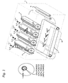
- Fig. 1 Electrophotographic printer
- FIG. 1 shows an electrophotographic/laser color printer 1 in which embodiments of the invention may be implemented.
- the laser color printer works as follows:
- a corona wire 2 projects an electrostatic charge onto the photoreceptor (otherwise named the photoconductor unit), which is in the example shown a set of four revolving photosensitive drums (3.1 - 3.4) for each of the primary colors cyan, magenta, yellow and black, each of which is capable of holding an electrostatic charge on its surface while it is in the dark.
- the photoreceptor also named the photoconductor unit
- the photoconductor unit a set of four revolving photosensitive drums (3.1 - 3.4) for each of the primary colors cyan, magenta, yellow and black, each of which is capable of holding an electrostatic charge on its surface while it is in the dark.
- Each laser 4 (4.1 - 4.4) is aimed at a rotating mirror 5 (5.1 -5.4), which directs the laser beam through a system of lenses and mirrors onto the photoreceptors.
- the beam sweeps across the photoreceptors at an angle to make the sweep straight across the page; each drum (3.1 - 3.4) continues to rotate during the sweep and the angle of sweep compensates for this motion.
- Lasers are used because they generate a narrow beam for great distances.
- the laser beam neutralizes (or reverses) the charge on the white parts, leaving a mirror image of static electricity on the photoreceptor surface to lift dry powder or liquid toner 6.
- a stream of halftone image data held in a memory controls the laser 4.1 - 4.4 by turning it on and off. When powering the laser for example with 66% or 33% of its full power, the charge on the drums 3.1 - 3.4 is not fully neutralized which allows the definition of pixels of intermediate intensities.
- the toner particles are charged, and are attracted to the areas of the photoreceptor 3 which were exposed by the laser light. Those toner particles 6 will then be transferred to paper 8 so that they form the image. In some printers the toner 6 is transferred to an intermediate transfer belt 7 or an intermediate transfer drum and then to the paper 8.
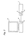
- Fig. 2 is a schematic diagram of a printing system, according to embodiments of the invention, which includes a host computer 12, a monitor 13 (e.g. a CRT), and the electrophotographic printer 1 of Fig. 1 .
- a host computer 12 e.g. a CRT
- a monitor 13 e.g. a CRT
- the electrophotographic printer 1 of Fig. 1 e.g. a CRT
- the functionalities described herein for printing may be implemented using a combination of hardware and software, whereby portions of the hardware/software are incorporated in the host computer 12 as software, for example, in the form of a printer driver 15, and other portions are located in color laser printer 1 in the form of hardware, such as the printer controller 14, for example, a PAL, PLA or FPGA.
- embodiments of the invention may be implemented (a) solely as software on the computer 12, or (b) solely on the printer 1 as hardware, e.g. in the form of an intelligent printer controller 14.
- embodiments of the invention may be implemented (c) partly on the computer 12 and partly on the printer 1.
- the location of the hardware/software for carrying out the different aspects of the invention is a matter of design choice.
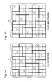
- Fig. 3 Halftone tiles for cyan and magenta
- Halftone tiles are matrices containing thresholds which are replicated over an image to be reproduced. According to the methods described herein, highlight areas of an image are generated with tiles of single pixels set to 100% exposure (without any further exposure added). The distribution of those initial pixels (cluster centers) - and their size - determines the perceived noise, so the selection of which pixels are turned on for each level is very critical. Fortunately, because individual dots are isolated on the page, they lend themselves to automated distribution algorithms based on frequency response. These methods return the order on which the pixels are turned on so that the visibility of the dot pattern is minimized.
- the method may be conceived as a hybrid of FM- and AM-halftoning.
- Fig. 3a shows a 10 x 10 tile for cyan.
- the crosses refer to pixels indicating cluster/dot centers ("seeds") represented as thresholds which indicate the order in which pixels of the screen are turned on, i.e. set from 0% exposure to 100% exposure to form individual dots.
- the cyan tile is subdivided into four 5 x 5 cells.
- a dot includes 10 pixels; after the center pixel of a dot has been turned on (set to 100% exposure), the dot may grow until its ten pixels are all set to 100% with increasing continuous-tone values to be represented.
- the image to be printed is digitally defined by a set of continuous-tone values (typically 8-bit for each of the primary colors cyan, magenta, yellow and black).
- the spatial resolution is such that one continuous-tone value is represented by one dot (10 pixels), whereby a small dot will represent a small continuous-tone value (highlight color), and a larger continuous-tone value (shadow) may be represented by a larger dot, in which many pixels will be set to 100% exposure.
- a black tile is selected so that it does not cause moiré patterns when mixed with the patterns of other colors.
- a tile which generates a pattern at a 45°-angle performs well, and such patterns are commonly used when designing the black halftone.
- the set of tiles may be completed by an ordinary yellow tile. Please note the black and yellow tiles are not used in the methods described below and are therefore not depicted.
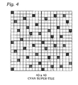
- Fig. 4 refers to a 40 x 40 super-tile which is composed of four cyan tiles shown in Fig. 3a .
- a 40 x 40 super-tile which is composed of four cyan tiles shown in Fig. 3a .
- Fig. 4 - an example of the cyan screen - shows how some dots have been replaced relative to the regular cyan tile shown in Fig. 3a . Some dots are located on the dot center and others above the dot center (the shifts are indicated by arrows).
- the exposure is added to each dot in the same order which was used when turning on the dots in the highlights.
- Fig. 5 shows an 120 x 120 super-tile which is composed of 144 10 x 10-tiles shown in Fig. 3 .
- the pixel structure is not the same for all the individual 10 x 10 tiles since the frequency optimization algorithm has generated 144 slightly different tiles.
- the actual transformation of the digitally represented image to the halftone image will be performed by repeating such a 120 x 120 halftone super-tile across the image.
- Fig. 6 shows the dot growth after one pixel has been activated for each dot.
- generating dot patterns for increasing continuous-tone values was done according to an FM-halftoning procedure.
- the individual dots which are only pixel
- growing continuous-tone values to be represented as halftone screens the same exposure is added to each dot, so that the dot structure is/remains regular.
- the process continues adding pixels to each cluster until all pixels in the pattern is set to 100%, for the darkest continuous-tone level.
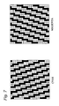
- Fig. 7 Dot growth in a linearized manner
- Fig. 6 within a dot, the pixel order is defined to generate a line screen.
- Fig. 7 A continuation of this process is shown in Fig. 7 , in which the left-hand figure shows for cyan the further growth of dots to form a line structure, whereas the right-hand figure refers to further dot growth for magenta.
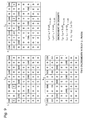
- Fig. 8 Distribution of pixels with different exposures in totally regular screens
- Fig. 8 shows which partial exposure is selected for the activated pixels.
- Fig. 8 refers to a 120 x 120 super-tile having 14400 pixels to represent a continuous-tone value. It will now be explained, below, how the different dot screens are obtained starting with dot patterns for low continuous-tone values and going over to higher values.
- a first phase (dot turn-on phase) pixels are activated to 100% exposure until 1440 pixels are activated; these represent the centers of 1440 clusters/dots ("seeds"). Now, all dots include one pixel set to 100%, and the dot turn-on phase has finished.
- the dot turn-on phase may also be conceived as an FM-phase.
- a second phase begins which adds to each 100%-pixel a neighboring pixel with a partial exposure of 33%.
- a dot-growth definition i.e. in which order individual pixels forming a dot are set
- the pixel directly below the center pixel is set to 33%.
- the order of pixels set from 0% to 33% is the same as the order from 0% to 100% in the dot turn-on phase.
- each of the 1440 dots includes a pixel of 100% and a pixel of 33%.
- each of the 1440 two-pixel dots includes a pixel of 100% and a pixel of 66%.
- each of the 1440 two-pixel dots includes two pixels of 100%.
- a "three-pixels-set-per-dot-stage” commences in which 1440 pixels of 0% are set to 33% in the same order as defined by the dot turn-on sequence described above in the second phase.
- the pixel set to 33% is the pixel above the center pixel.
- the 1440 pixels of 33% are increased to an exposure of 66%, and finally, the 1440 66%-pixels are set to 100% exposure.
- all 1440 dots (clusters) include 3 pixels of 100%, and the "three-pixels-set-per-dot-stage" has finished.
- Fig. 9 Two density increments within one phase
- the individual clusters are extended by adding partial exposures.
- the drawback of this approach is the sensibility of the tone ramp to variations of the partial exposure. Because all the clusters use the same exposure level, variations of that exposure level have a relatively strong impact on the density produced by the tile. To achieve uniform density increases, the exposure level must be selected carefully to avoid contouring. Contouring effects come into being when a uniform increase of continuous-tone values is represented by halftone dot patterns whose increase in darkness appears to be non-uniform (yielding the impression of "jumps" in the dot patterns).
- Density is the degree to which materials such as ink, paper and film absorb light. The more light one of these materials absorbs, the higher is the density.
- the corresponding devices which measure density are referred to as "densitometers". In fact, densitometers do not measure density but rather the ratio between the intensity (I 0 ) of light shone on or through a surface, and the light that reaches the detector in the instrument. This ratio is called reflectance (R) or the transmittance, depending on whether the instrument measures reflective materials such as ink and paper, or transmissive materials such as film.
- the problem is that the increases in density (which depends on the sizes of the dots) are not proportional to the increase in exposure.
- increasing a dot having a 1 00%-pixel to a dot having a 100%-pixel and a 33%-pixel does not increase the size S of the dot to the same amount as an increase in exposure from a dot including a pixel of 100% and a pixel of 33% to a dot including a pixel of 100% and a pixel of 66%.
- the increase in size from a dot including a pixel of 100% and a pixel of 66% to two pixels of 100% may also be different from the two increases just mentioned (1 ⁇ 1.33, 1.33 ⁇ 1.66).
- Fig. 9 refers to the situation in which dots of individual 1 00%-pixels are replaced with dots of a 100%-pixel and a 33%-pixel.
- the first dot screen of Fig. 9 shows a dot pattern after the dot turn-on, in which ten dots of 100%-pixels exist.
- This dot pattern has a density level which is referred to as L 0 .
- two increments are performed each of which increases the power of the laser/exposure by the same amount. It is then checked which increase of dot size is obtained.
- Two of the dots (having a 100% pixel) are changed into a dot which is composed of a 100%-pixel and a 33%-pixel.
- This dot pattern has a density level L 1 .
- L 1 L 0 + 2 ⁇ ⁇ ⁇ S 1 ⁇ 1.33
- L 2 L 1 + 2 ⁇ ⁇ ⁇ S 1 ⁇ 1.33
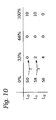
- Fig. 10 summarizes the idea presented in Fig. 9 by means of showing the numbers of pixels changed.
- L 0 refers to a density level in which 60 pixels are set to 0%, and 10 pixels are set to 100%.
- Density level L 1 is obtained by increasing the exposure of two 0%-pixels to an exposure of 33%, while the number of 100%-pixels is kept constant.
- density level L 2 is obtained by increasing the exposure of two 0%-pixels to an exposure of 33%.
- Fig. 11 Density increment of 3 rd and 4 th phase
- Fig. 11 shows the transitions made in the 3 rd phase (see Fig. 8 ) from density level L 0 to density level L 1 , in which pixels are set from 33% to 66% intensity. Moreover, it shows the transition made in the 4 th phase (see Fig. 8 ) from density level L 1 to density level L 2 . It is noted that the laser power needed to get from L 0 to L 1 is the same as to get from L 1 to L 2 . However, attention is drawn to the fact that the increase in density is not the same. To get from L 0 to L 1 , 10 pixels are set from 33%-exposure to 66%, which increase the sizes of the corresponding dots by an amount denoted as 10 ⁇ S 1.33 ⁇ 1.66 .
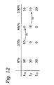
- Fig. 12 summarizes the change in numbers of pixels of different intensities when going from L 0 to L 1 and from L 1 to L 2 (see Fig. 11 ).
- 50 pixels of 0% exposure, 10 pixels of 33% exposure, 0 pixels of 66% exposure and 10 pixels of 100% exposure are provided.
- all 10 33%-pixels are set from 33% to 66%, or to put it differently, only pixels of one sort (namely the 33%-pixels) are increased in exposure.
- only pixels of one sort namely the 33%-pixels
- only pixels of 66% exposure are increased in exposure. Since in each step, only pixels of one sort are increased in exposure, the increase in size/density is not the same for the two steps. Using halftone patterns like this may lead to contouring effects.
- Fig. 13 Distribution of pixels with different exposures in partially regular clusters
- Fig. 13 shows the numbers of pixels with zero power/exposure (curve A), 33% power (curve B), 66% power (curve C) and 100% power (curve D).
- a 120 x 120 super-tile is used on a homogenous part of an image having the same continuous-tone value.
- 0%-pixels are set to 100%-pixel which form the center of the dots (clusters).
- all 1440 clusters include a single 100%-pixel.
- the procedure continues in the same way as explained in Fig. 8 , until all 1440 dots include four 100%-pixels.
- the method would still be valid if the number of pixels on intermediate values were allowed to vary while keeping it substantially constant, say within 20% of the nominal number of pixels.
- Fig. 14 illustrates two steps which add exposures of different levels such that the increase of density of the first step is the same as the increase of density of the second step.
- L 0 refers to the level of density of a dot having a 100% pixel, a dot having a 100%-pixel and a 33%-pixel, and a dot having a 100%-pixel and a 66%-pixel.
- the density of the pattern is increased by changing a 0%-pixel into a 33%-pixel, the 33%-pixel into a 66%-pixel and the 66%-pixel into a 100%-pixel.
- the increase of density when going from level L 0 to level L 1 is the same as the increase of density when going from level L 1 to level L 2 . It should be mentioned that it would also be within the scope of the invention to simply add one 100%-pixel to the dot pattern of L 0 . However, to obtain the desired dot shape, it may be reasonable to change the pixels from one intensity to the next higher level of intensity.
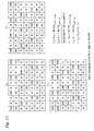
- Fig. 15 Change in numbers: shifting the pixels into higher levels
- Fig. 15 summarizes the number of pixels of the different intensities.
- density level L 0 23 0%-pixels, one 33%-pixel, one 66%-pixel and three 1 00%-pixels are provided.
- one of the 0%-pixels is set to 33%, the 33%-pixel is set to 66%, and the 66%-pixel is set to 100%.
- one of the 0%-pixels is set to 33%, the 33%-pixel is set to 66%, and the 66%-pixel is set to 100%. Consequently, in L 2 , there are 21 pixels of 0%, one pixel of 33%, one pixel of 33%, and 5 pixels of 100%.
- the change in numbers of pixels of the different intensities may also be conceived as shifting pixels from one intensity level into the next higher intensity level. In effect, the intermediate intensity levels remain constant in numbers.
- the step from L 0 to L 1 and from L 1 to L 2 refers to the same increment of density.
- This effect is obtained by an averaging effect since in both steps, density increments of all three types (1 ⁇ 1.33, 1.33 ⁇ 1.66, 1.66 ⁇ 2) are performed.
- halftone dot patterns having undesired contouring effects may be reduced since a uniform increase in continuous-tone values is reproduced by a uniform increase of the density of the dot patterns.
Landscapes
- Engineering & Computer Science (AREA)
- Multimedia (AREA)
- Signal Processing (AREA)
- Physics & Mathematics (AREA)
- Discrete Mathematics (AREA)
- General Physics & Mathematics (AREA)
- Color, Gradation (AREA)
- Facsimile Image Signal Circuits (AREA)
Priority Applications (1)
| Application Number | Priority Date | Filing Date | Title |
|---|---|---|---|
| EP07014205A EP2018040A1 (de) | 2007-07-19 | 2007-07-19 | Konturierungsverringerung beim Rastern |
Applications Claiming Priority (1)
| Application Number | Priority Date | Filing Date | Title |
|---|---|---|---|
| EP07014205A EP2018040A1 (de) | 2007-07-19 | 2007-07-19 | Konturierungsverringerung beim Rastern |
Publications (1)
| Publication Number | Publication Date |
|---|---|
| EP2018040A1 true EP2018040A1 (de) | 2009-01-21 |
Family
ID=38740514
Family Applications (1)
| Application Number | Title | Priority Date | Filing Date |
|---|---|---|---|
| EP07014205A Withdrawn EP2018040A1 (de) | 2007-07-19 | 2007-07-19 | Konturierungsverringerung beim Rastern |
Country Status (1)
| Country | Link |
|---|---|
| EP (1) | EP2018040A1 (de) |
Citations (6)
| Publication number | Priority date | Publication date | Assignee | Title |
|---|---|---|---|---|
| GB2091518A (en) * | 1981-01-21 | 1982-07-28 | Dainippon Screen Mfg | A method for producing a halftone plate |
| US5077615A (en) * | 1989-08-24 | 1991-12-31 | Ricoh Company, Ltd. | Halftone image recording apparatus combining error scattering and multi-level tone conversion techniques |
| EP0892549A2 (de) * | 1992-06-05 | 1999-01-20 | Eastman Kodak Company | Verfahren und Gerät zur Bildreproduktion mittels Grautondruck |
| US20040017415A1 (en) * | 2002-04-05 | 2004-01-29 | Seiko Epson Corporation | Printing with variable dot-recording rate in response to dot size error |
| EP1631056A1 (de) * | 2004-08-27 | 2006-03-01 | Konica Minolta Holdings, Inc. | Bilderzeugungsvorrichtung und Bilderzeugungsverfahren |
| WO2006104041A1 (ja) * | 2005-03-29 | 2006-10-05 | Dai Nippon Printing Co., Ltd. | 画像データ生成装置、画像データ生成処理プログラム、及び熱転写記録装置等 |
-
2007
- 2007-07-19 EP EP07014205A patent/EP2018040A1/de not_active Withdrawn
Patent Citations (6)
| Publication number | Priority date | Publication date | Assignee | Title |
|---|---|---|---|---|
| GB2091518A (en) * | 1981-01-21 | 1982-07-28 | Dainippon Screen Mfg | A method for producing a halftone plate |
| US5077615A (en) * | 1989-08-24 | 1991-12-31 | Ricoh Company, Ltd. | Halftone image recording apparatus combining error scattering and multi-level tone conversion techniques |
| EP0892549A2 (de) * | 1992-06-05 | 1999-01-20 | Eastman Kodak Company | Verfahren und Gerät zur Bildreproduktion mittels Grautondruck |
| US20040017415A1 (en) * | 2002-04-05 | 2004-01-29 | Seiko Epson Corporation | Printing with variable dot-recording rate in response to dot size error |
| EP1631056A1 (de) * | 2004-08-27 | 2006-03-01 | Konica Minolta Holdings, Inc. | Bilderzeugungsvorrichtung und Bilderzeugungsverfahren |
| WO2006104041A1 (ja) * | 2005-03-29 | 2006-10-05 | Dai Nippon Printing Co., Ltd. | 画像データ生成装置、画像データ生成処理プログラム、及び熱転写記録装置等 |
Similar Documents
| Publication | Publication Date | Title |
|---|---|---|
| US5859955A (en) | Stochastically clustered dot halftoning system | |
| US5903713A (en) | Moire free multilevel halftoning of color images | |
| US5142337A (en) | Printing grey scale images | |
| EP2544443B1 (de) | Schwellenwertmatrixerzeugungsvorrichtung und -verfahren zur Erzeugung einer Schwellenwertmatrix von zuvor festgelegter Größe, die zur Halbtonverarbeitung von Mehrtonbilddaten unter Verwendung des Ditheringverfahrens verwendet wird | |
| JP3428728B2 (ja) | グレイピクセルハーフトーンエンコーダ | |
| US4868587A (en) | Image halftoning system for printers | |
| CN100570500C (zh) | 图像处理装置、图像处理方法和图像形成装置 | |
| US6917443B1 (en) | Composite halftone screens with stochastically distributed clusters or lines | |
| US6252679B1 (en) | Composite halftone screens with stochastically distributed clusters or lines | |
| JP2644666B2 (ja) | 印刷装置 | |
| US5740279A (en) | Cluster dot halftoning system | |
| US6304340B1 (en) | Composite halftone screens with stochastically distributed clusters or lines | |
| US5184183A (en) | Apparatus for printing grey scale images | |
| US7130084B2 (en) | Electrophotographic apparatus and image processing program | |
| US7440141B2 (en) | Method for generating a dither mask | |
| US5406379A (en) | Method of hybrid halftone printing by limiting the number of gray pixels and gray pixel levels | |
| US5627919A (en) | Image forming method and apparatus | |
| US4963990A (en) | Continuous halftoning using quarternary pixel cells | |
| US5786843A (en) | Two-dimensional modulation for line screen printing | |
| US20060279788A1 (en) | Automatic generation of supercell halftoning threshold arrays for high addressability devices | |
| JP2004135317A (ja) | カラー画像処理装置およびカラー画像処理方法 | |
| EP2018040A1 (de) | Konturierungsverringerung beim Rastern | |
| JP4442481B2 (ja) | 画像形成装置 | |
| JP3711763B2 (ja) | 電子写真の画像処理装置及びその方法 | |
| EP0932301B1 (de) | Steuerung der entwickelten Tonermenge unter Verwendung von Lasermodulationen von getrennten Unterelementen eines Bildes |
Legal Events
| Date | Code | Title | Description |
|---|---|---|---|
| PUAI | Public reference made under article 153(3) epc to a published international application that has entered the european phase |
Free format text: ORIGINAL CODE: 0009012 |
|
| AK | Designated contracting states |
Kind code of ref document: A1 Designated state(s): AT BE BG CH CY CZ DE DK EE ES FI FR GB GR HU IE IS IT LI LT LU LV MC MT NL PL PT RO SE SI SK TR |
|
| AX | Request for extension of the european patent |
Extension state: AL BA HR MK RS |
|
| 17P | Request for examination filed |
Effective date: 20090209 |
|
| 17Q | First examination report despatched |
Effective date: 20090312 |
|
| AKX | Designation fees paid |
Designated state(s): DE GB |
|
| STAA | Information on the status of an ep patent application or granted ep patent |
Free format text: STATUS: THE APPLICATION IS DEEMED TO BE WITHDRAWN |
|
| 18D | Application deemed to be withdrawn |
Effective date: 20090723 |