EP2017930B1 - Plasma ignition system - Google Patents
Plasma ignition system Download PDFInfo
- Publication number
- EP2017930B1 EP2017930B1 EP08160493.6A EP08160493A EP2017930B1 EP 2017930 B1 EP2017930 B1 EP 2017930B1 EP 08160493 A EP08160493 A EP 08160493A EP 2017930 B1 EP2017930 B1 EP 2017930B1
- Authority
- EP
- European Patent Office
- Prior art keywords
- discharge space
- center electrode
- insulating member
- recess portion
- electrode
- Prior art date
- Legal status (The legal status is an assumption and is not a legal conclusion. Google has not performed a legal analysis and makes no representation as to the accuracy of the status listed.)
- Expired - Fee Related
Links
Images


Classifications
-
- H—ELECTRICITY
- H01—ELECTRIC ELEMENTS
- H01T—SPARK GAPS; OVERVOLTAGE ARRESTERS USING SPARK GAPS; SPARKING PLUGS; CORONA DEVICES; GENERATING IONS TO BE INTRODUCED INTO NON-ENCLOSED GASES
- H01T13/00—Sparking plugs
- H01T13/50—Sparking plugs having means for ionisation of gap
-
- F—MECHANICAL ENGINEERING; LIGHTING; HEATING; WEAPONS; BLASTING
- F02—COMBUSTION ENGINES; HOT-GAS OR COMBUSTION-PRODUCT ENGINE PLANTS
- F02P—IGNITION, OTHER THAN COMPRESSION IGNITION, FOR INTERNAL-COMBUSTION ENGINES; TESTING OF IGNITION TIMING IN COMPRESSION-IGNITION ENGINES
- F02P9/00—Electric spark ignition control, not otherwise provided for
- F02P9/002—Control of spark intensity, intensifying, lengthening, suppression
- F02P9/007—Control of spark intensity, intensifying, lengthening, suppression by supplementary electrical discharge in the pre-ionised electrode interspace of the sparking plug, e.g. plasma jet ignition
Definitions
- the present invention relates to measures against electrode wear and improvement in ignition stability in a plasma ignition system used for ignition of an internal combustion engine.
- a plasma ignition system 1x shown in FIG. 11A is known.
- the system 1x by applying high voltage between a center electrode 110x and a ground electrodes 130x of the plasma ignition plug 10x from a discharge power source 20x and by supplying a high current from a plasma generation power source 30x at the moment of the start of electric discharge in a discharge space 140x formed between the center electrode 110x and the ground electrode 130x, gas in the discharge space 140x is put into a plasma state of high-temperature and pressure and then the gas is injected from a leading end of the discharge space 140x so as to carry out ignition.
- the plasma ignition system 1x has good directivity and generates a very high temperature range from thousands to tens of thousands of degrees Kelvin (K) in a broad range in volume, the system 1x is expected to be applied as an ignition system for a lean burn engine having ignition resistance, such as homogeneous lean burn or stratified lean burn.
- K degrees Kelvin
- a surface gap spark plug is disclosed in USP 3, 581, 141 to prevent deterioration of the center electrode.
- the above surface gap spark plug includes a center electrode, an insulator having an insertion hole in its center, the hole holding the center electrode and extending longitudinally, a ground electrode, which covers the insulator and has an opening at its lower end, the opening communicating with the insertion hole, and a discharging gap, which is formed in the insertion hole.
- JP-U-56-35793 disclosing a plasma ignition system, according to the preamble of claim 1.
- the discharge voltage is lowered by forming a projection or a recess, where an electric field density is locally high, at an end portion of a discharge surface of a center electrode.
- the center electrode is used as a negative pole and the ground electrode is used as a positive pole.
- cathode sputtering whereby the center electrode 110x is decomposed is easily generated, since a positive ion 50x having high temperature and large mass collides with a surface of the center electrode 110x.
- the surface of the center electrode 110x is heavily eroded due to the cathode sputtering.
- a discharge distance 141x between the center electrode 110x and the ground electrode 130x becomes gradually longer because of the erosion of the center electrode 110x.
- the discharge voltage rises gradually in proportion to the discharge distance 141x, and when the discharge voltage reaches a generated voltage of the discharge power source 20x or above in the course of time, electricity cannot be discharged and accordingly, there is a possibility of an accidental fire of the engine.
- the center electrode When the portion where the electric field density is locally high is formed on the surface of the center electrode through the formation of the projection or recess, as in the device in JP-U-56-35793 , the center electrode still serves as a negative pole, so that the consumption of the center electrode due to the cathode sputtering is unavoidable, although an effect of reducing the discharge voltage is produced in its initial use. More specifically, the portion having the high electric field density is consumed first and consequently, the discharge voltage gradually rises. Eventually, there is a possibility of an accidental fire of the engine.
- the present invention addresses the above disadvantages.
- a plasma ignition system 1 of the first embodiment includes a high voltage power having a discharge power source 20 and a plasma generation power source 30, and a plasma ignition plug 10.
- the plasma ignition plug 10 includes a center electrode 110, a cylindrical insulating member 120, which insulates and holds the center electrode 110, and an annular ground electrode 130, which covers the insulating member 120.
- a lower end portion of the center electrode 110 is formed into a shaft shape having a diameter of ⁇ D1.
- a leading end side of the center electrode 110 is formed from a high melting point material such as Fe (iron) or Ni (nickel), and a center-electrode axis 112 including a highly conductive metallic material such as Cu (copper) or a ferrous material is formed in the center electrode 110.
- a high melting point material such as Fe (iron) or Ni (nickel)
- a center-electrode axis 112 including a highly conductive metallic material such as Cu (copper) or a ferrous material is formed in the center electrode 110.
- the insulating member 120 is formed from, for example, highly-pure alumina, which is excellent in heat resistance, mechanical strength, dielectric strength at high temperature, and heat conductivity.
- the cylindrical discharge space 140 extending downward from a leading end surface of the center electrode 110 and having an inner diameter D1 and length G1 is formed on a leading end side of the insulating member 120.
- a center-electrode locking part which catches the housing 135 via a packing member for maintaining airtightness between the insulating member 120 and a housing 135, is formed in a halfway area of the insulating member 120.
- An insulating member head portion which insulates the center electrode 110 from the housing 135 and prevents high voltage from escaping to other areas than the center electrode 110, is formed on a rear end side of the insulating member 120.
- a leading end portion of the housing 135 covers an outer circumference of the insulating member 120, and an annular ground electrode 130, a leading end of which is crooked inward, is formed at the leading end portion of the housing 135.
- a housing thread part 132 for fixing the plasma ignition plug 10 to a wall surface (engine block 40) of an internal combustion engine (not shown) such that the ground electrode 130 is exposed to the inside of the engine and for putting the ground electrode 130 and the engine block 40 into a electrically grounded state is formed on an outer peripheral part of a halfway area of the housing 135.
- a housing hexagon head part 133 for fastening the housing thread part 132 is formed on an outer peripheral part of a rear end side of the housing 135.
- the ground electrode 130 has a ground electrode opening 131, which communicates with the inside of the insulating member 120 and is opposed to the discharge space 140.
- An opening diameter ⁇ D1 of a lower end of the recess portion 111 of the center electrode 110 is generally the same as an inner diameter ⁇ D2 of the insulating member 120, which defines the discharge space 140.
- a relationship between the recess portion opening diameter ( ⁇ D1) and the insulating member inner diameter ( ⁇ D2) may satisfy D2 ⁇ D1, or the recess portion 111 and the insulating member 120 may be formed such that a difference in level is not caused between an inner surface of the recess portion 111 and an inner surface of the insulating member 120 due to a difference between the recess portion opening diameter ( ⁇ D1) and the insulating member inner diameter ( ⁇ D2).
- volume of the recess portion 111 at its portion close to the discharge path is maximized, the supplied energy is most efficiently utilized for putting the gas in the discharge space 140 and the recess portion 111 into the plasma state.
- a relationship between an outer diameter ⁇ D3 of the center electrode 110 at its portion serving as an inner circumferential wall of the recess portion 111 and the inner diameter ⁇ D2 of the insulating member 120 defining the discharge space 140 is set to satisfy D2 ⁇ D3 ⁇ 2xD2.
- the electric field density at a portion of the recess portion 111 serving as its vertical wall becomes high and consequently, the discharge voltage is made even lower.
- a relationship among a distance G1 from a lower end surface of the center electrode 110 to a surface of the ground electrode 120 at a boundary between the ground electrode 130 and a lower end portion of the insulating member 120, the depth G2 of the recess portion 111, volume V1 of the discharge space 140, and the volume V2 of the recess portion 111 is set to satisfy G2 ⁇ G1 and V1 ⁇ V1 +V2 ⁇ 2xV1.
- the recess portion 111 When the recess portion 111 is enlarged too much, an amount of the gas that is put into the plasma state becomes smaller than the total volume Vt of the volume V1 of the discharge space 140 and the volume V2 of the recess portion 111, since an amount of gas that is able to be ionized by a constant discharge voltage is limited. Accordingly, the volume V1 and the volume V2 have their optimum values. More specifically, by forming the recess portion 111 to satisfy the above-prescribed ranges, the gas in the discharge space 140 and the gas in the recess portion 111 are most efficiently put into the plasma state. As a result, the plasma ignition system 1, which is extremely excellent in durability and excellent in ignition stability of the engine, is realized.
- polarities of the discharge power source 20 and the plasma generation power source 30 are set such that the center electrode 110-side serves as a positive pole and the ground electrode 130-side serves as a negative pole.
- the discharge power source 20 includes a first battery 21, an ignition key 22, an ignition coil 23, an igniter having a transistor, and an electronic control unit (ECU) 25.
- the discharge power source 20 is connected to the plasma ignition plug 10 through a first rectifying device 26. A positive pole side of the first battery 21 is grounded.
- the plasma generation power source 30 includes a second battery 31, a resistance 32, and a plasma generation capacitor 33.
- the plasma generation power source 30 is connected to the plasma ignition plug 10 through a second rectifying device 34.
- a negative pole side of the second battery 31 is grounded.
- a negative and low primary voltage is applied to a primary coil 231 of the ignition coil 23 from the first battery 21 in response to an ignition signal from the ECU 25.
- the primary voltage is cut off by switching of an ignition coil drive circuit 24, a magnetic field in the ignition coil 23 changes and accordingly, a positive secondary voltage ranging from 10 to 30kV is induced in a secondary coil 232 of the ignition coil 23 due to a self-induction effect.
- the plasma generation capacitor 33 is charged by the second battery 31.
- the applied secondary voltage is larger than a discharge voltage proportional to a discharge distance 141 between the center electrode 110 and the ground electrode 130, electric discharge is started between both the electrodes and thereby gas in the discharge space 140 is put into a plasma state in a small region.
- the gas in the plasma state has conductivity and causes discharge of electric charge stored between both poles of the plasma generation capacitor 33. Accordingly, the gas in the discharge space 140 is further put into the plasma state and the above region is expanded.
- the gas in the plasma state has high temperature and pressure and is injected into a combustion chamber of the engine. Meanwhile, not only the gas in the discharge space 140 but also gas in the recess portion 111 is put in the plasma state of high temperature and pressure. Therefore, a plasma injection length Lp becomes very long.
- a collision angle of the positive ion 50 is shallow and thereby collision force of the positive ion 50 is mitigated because the opening 131 is disposed in a direction generally perpendicular to an injection direction of the gas in the plasma state.
- the ground electrode 130-side easily releases heat to the engine block 40 and is thereby easily cooled despite the collision with the high-temperature positive ion 50, so that the ground electrode 130 is resistant to its consumption caused by cathode sputtering.
- the positive ion 50 does not collide with a surface of the center electrode 110 serving as a positive pole because the positive ion 50 is repelled by the surface due to electrostatic repulsion. Only an electron 51 having small mass collides with the surface of the center electrode 110 and accordingly erosion due to the cathode sputtering does not take place easily.
- a first comparative example is configured not to include a recess portion 111
- a second comparative example is configured such that an outer diameter ⁇ D3 of a center electrode 110 is equal to an inner diameter ⁇ D1 of an insulating member 120 and that an inner diameter ⁇ D2 of a recess portion 111 is smaller than the outer diameter ⁇ D3 of the center electrode 110.
- the first embodiment is configured such that the outer diameter ⁇ D3 of the center electrode 110 is larger than the inner diameter ⁇ D1 of the insulating member 120 and that the inner diameter ⁇ D2 of the recess portion 111 is equal to the inner diameter ⁇ D1 of the insulating member 120, and a second embodiment of the invention is configured such that the depth G2 of the recess portion 111 is larger than the first embodiment.
- Table 1 1st comparative example 2nd comparative example 1st embodiment 2nd embodiment Outer dia. of center electrode ⁇ D3 1.3mm 1.3mm 2.0mm 2.0mm Inner dia. of discharge space ⁇ D2 1.3mm 1.3mm 1.3mm 1.3mm Inner dia.
- an electric field density of a portion defining a vertical wall of the recess portion 111 is increased due to the existence of the recess portion 111, and thereby electricity is easily discharged.
- the inner diameter ⁇ D2 of the recess portion 111 is generally equal to the inner diameter ⁇ D1 of the insulating member 120, a distance between a corner portion of an opening at a lower end of the recess portion 111 and a creeping-discharge path formed to creep on a surface of an inner circumferential wall of the insulating member 120 is extremely small, and a discharge voltage V becomes even lower.
- FIG. 3 shows the result of measurement of the plasma injection length Lp with respect to the first comparative example, the second comparative example, the first embodiment, and the second embodiment. As shown in FIG. 3 , according to the invention, the plasma injection length Lp is most lengthened.
- FIG. 4 is a characteristic diagram illustrating the result of the measurement of the plasma injection length Lp when discharge space total volume Vt is changed in a more detailed manner to verify the effects of the invention.
- the plasma injection length Lp gradually becomes longer as the discharge space total volume Vt becomes larger. Nevertheless, when the discharge space total volume Vt becomes equal to or larger than certain volume, the plasma injection length Lp becomes conversely shorter. Also, the plasma injection length Lp becomes longer in the case where the recess portion 111 is formed than in the case where the recess portion 111 is not formed, despite the same discharge space total volume Vt.
- FIGS. 5 to 10 is a partly cutaway perspective view illustrating a main portion of a plasma ignition plug 10 used for a plasma ignition system 1 according to embodiments of the invention.
- their basic configurations are the same as the first embodiment, and a shape of an inner circumferential wall of a recess portion 111 of the plasma ignition plug 10 or an inner circumferential wall of an insulating member 120 is different from the first embodiment.
- a minimum distance from a surface of an uppermost part of the ground electrode 130 to a surface of a lowermost part of the center electrode 110 is the discharge distance 141 and accordingly, the discharge voltage is constant.
- the electrons 51 are emitted to the space defined by the inner circumferential wall of the recess portion 111, as well as to the discharge space 140 defined by an inner circumferential wall of the insulating member 120. Accordingly, the volume of the gas, which is put into the plasma state, is increased without increasing the discharge voltage.
- the center electrode 110 serves as a positive pole.
- the positive ion 50 having large mass is repelled by the center electrode 110 due to the electrostatic repulsion, and only the electron 51 having small mass collides with the center electrode 110. Consequently, the center electrode 110 is not easily eroded due to the cathode sputtering. Therefore, according to the invention, the durability of the plasma ignition system 1 is improved, and an amount of the gas that is put into the plasma state is increased with respect to a constant discharge voltage, so that the ignitionability of the engine is improved.
- the ground electrode 130 serving as a negative pole can be eroded due to the cathode sputtering, a collision angle of the positive ion 50 with the ground electrode 130 is shallow, and thus the collision force of the positive ion 50 is eased, because the surface of the ground electrode 130 faces in a direction generally perpendicular to the injection direction of the gas in the plasma state.
- the ground electrode 130-side easily releases heat to the grounded part of the engine, the consumption of the electrodes is not easily caused by the cathode sputtering compared to when the center electrode 110 is used as a negative pole in a conventional manner.
- the durability of the plasma ignition system 1 that is excellent in ignition stability is further improved.
- a center-electrode recess portion 111a is formed in a shape of a half-ellipse spherical surface.
- the following advantageous effect is produced in addition to a similar effect to the first embodiment. That is, when the center-electrode recess portion 111 a is formed to have the same recess portion volume V2 as the first embodiment, a surface area of an inner circumferential wall of the center-electrode recess portion 111a is larger than the first embodiment. Accordingly, it is expected that a probability of occurrence of gas ionized by an electron released into the center-electrode recess portion 111 a is made high.
- a center-electrode recess portion 111 b is formed in a conical shape.
- a center-electrode recess portion 111 c is formed in a shape of a truncated cone.
- a plasma ignition plug 10d according to a fifth embodiment of the invention is configured such that a wall surface of a center-electrode recess portion 111 d is partly notched and an insulating member is inserted therebetween so as to achieve multipolarity.
- an inner circumferential wall of an insulating member 120e is formed in a conical shape, in which an inner diameter of the insulating member 120e becomes smaller in a direction from a center-electrode 110e-side toward a ground electrode 130e-side.
- the gas in the plasma state having high temperature and pressure, which is generated in the discharge space 140 is injected to be squeezed out through the narrow ground electrode opening 131e, the plasma injection length Lp becomes even longer, and as a result, the ignition stability is expected to be improved in the stratified combustion.
- an inner circumferential wall of an insulating member 120f is formed in a shape of a trumpet, in which an inner diameter of the insulating member 120f becomes larger in a direction from a center electrode 110f-side toward a ground electrode 130f-side.
- the invention is not limited to the above embodiments, and may be appropriately changed without departing from the scope of the invention.
- the plasma ignition system including a single plasma ignition plug is described.
- the invention may also be applied to a multiple cylinder engine including many ignition plugs.
- examples using the high voltage power having a plurality of power sources, that is, the discharge power source 20 and the plasma generation power source 30 are described.
- a power source for the application of high voltage and a power source for supply of a high current may constitute a single power source.
- a plasma ignition system (1) includes an ignition plug (10) attached to an engine and a high-voltage supply (20, 30).
- the plug includes a center electrode (110) serving as a positive pole, a ground electrode (130) serving as a negative pole, and an insulating member (120) insulating the center electrode from the ground electrode and defining a discharge space (140) therein. At least a part of a surface of the center electrode faces the space, and at least a part of a surface of the ground electrode faces the discharge space.
- the plug puts gas in the space into a plasma state and injects the gas into the engine as a result of application of high voltage and supply of a large current to the plug by the high-voltage supply.
- the center electrode has a recess portion (111) opposed to the space and recessed in a direction opposite to an injection direction.
Landscapes
- Spark Plugs (AREA)
- Ignition Installations For Internal Combustion Engines (AREA)
Description
- The present invention relates to measures against electrode wear and improvement in ignition stability in a plasma ignition system used for ignition of an internal combustion engine.
- In an internal combustion engine such as an automobile engine, a plasma ignition system 1x shown in
FIG. 11A is known. In the system 1x, by applying high voltage between acenter electrode 110x and aground electrodes 130x of theplasma ignition plug 10x from adischarge power source 20x and by supplying a high current from a plasmageneration power source 30x at the moment of the start of electric discharge in adischarge space 140x formed between thecenter electrode 110x and theground electrode 130x, gas in thedischarge space 140x is put into a plasma state of high-temperature and pressure and then the gas is injected from a leading end of thedischarge space 140x so as to carry out ignition. Because the plasma ignition system 1x has good directivity and generates a very high temperature range from thousands to tens of thousands of degrees Kelvin (K) in a broad range in volume, the system 1x is expected to be applied as an ignition system for a lean burn engine having ignition resistance, such as homogeneous lean burn or stratified lean burn. - As a conventional technology of such a plasma ignition system, a surface gap spark plug is disclosed in
USP 3, 581, 141 to prevent deterioration of the center electrode. The above surface gap spark plug includes a center electrode, an insulator having an insertion hole in its center, the hole holding the center electrode and extending longitudinally, a ground electrode, which covers the insulator and has an opening at its lower end, the opening communicating with the insertion hole, and a discharging gap, which is formed in the insertion hole. - Also, a technology which aims to lower discharge voltage is disclosed in
JP-U-56-35793 claim 1. According to the above technology, the discharge voltage is lowered by forming a projection or a recess, where an electric field density is locally high, at an end portion of a discharge surface of a center electrode. - However, in conventional plasma ignition systems such as
USP 3, 581, 141 andJP-U-56-35793 FIG. 11B , cathode sputtering whereby thecenter electrode 110x is decomposed is easily generated, since apositive ion 50x having high temperature and large mass collides with a surface of thecenter electrode 110x. The surface of thecenter electrode 110x is heavily eroded due to the cathode sputtering. Adischarge distance 141x between thecenter electrode 110x and theground electrode 130x becomes gradually longer because of the erosion of thecenter electrode 110x. The discharge voltage rises gradually in proportion to thedischarge distance 141x, and when the discharge voltage reaches a generated voltage of thedischarge power source 20x or above in the course of time, electricity cannot be discharged and accordingly, there is a possibility of an accidental fire of the engine. - When the portion where the electric field density is locally high is formed on the surface of the center electrode through the formation of the projection or recess, as in the device in
JP-U-56-35793 - On the other hand, when the application of high voltage and the high current emission are performed on the inside of a certain discharge space, creeping discharge is generated to creep on a surface of an
insulating member 120x, and gas around a creeping-discharge path is put into the plasma state. Because density of the gas in the plasma state immediately becomes high, further ionization of the gas becomes difficult despite the continuation of emission of electron. The volume of the discharge space needs to be enlarged in order to put more gas into the plasma state. However, according to the conventional configuration, when the volume of the discharge space is enlarged, the discharge distance becomes long, and accordingly discharge potential becomes high. - Furthermore, in stratified combustion of a lean mixture, accuracy in aiming the gas at a layer in the fuel/air mixture having high fuel concentration needs to be improved, by making an injection length of gas in the plasma state used as an ignition source as long as possible.
- The present invention addresses the above disadvantages. Thus, it is an objective of the present invention to provide a plasma ignition system, which restricts consumption of an electrode due to cathode sputtering to improve durability, and makes longer an injection length of gas in a plasma state to improve ignition stability.
- To achieve the objective of the present invention, there is provided a plasma ignition system for an internal combustion engine according to
claim 1. - Further features and advantageous modifications are shown in the dependent claims.
- The invention, together with additional objectives, features and advantages thereof, will be best understood from the following description, the appended claims and the accompanying drawings in which:
-
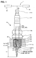
FIG. 1 is a schematic diagram illustrating a configuration of a plasma ignition system according to a first embodiment of the invention; -
FIG. 2 is a representative circuit schematic illustrating a circuit configuration of the plasma ignition system of the first embodiment; -
FIG. 3 is a characteristic graph illustrating advantageous effects of the first embodiment together with comparative examples; -
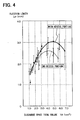
FIG. 4 is a characteristic graph illustrating the advantageous effects of the first embodiment; -
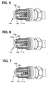
FIG. 5 is a cutaway perspective view illustrating a second embodiment of the invention, in which a center-electrode recess portion is formed in an ellipse spherical concave shape; -
FIG. 6 is a cutaway perspective view illustrating a third embodiment of the invention, in which a center-electrode recess portion is formed in a conical shape; -
FIG. 7 is a cutaway perspective view illustrating a fourth embodiment of the invention, in which a center-electrode recess portion is formed in a generally trapezoidal shape at its longitudinal section; -
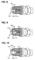
FIG. 8 is a cutaway perspective view illustrating a fifth embodiment of the invention, in which a center electrode is multipolarized; -
FIG. 9 is a cutaway perspective view illustrating a sixth embodiment of the invention, in which an inner circumferential wall of an insulating member is formed in a generally conical shape, a diameter of which decreases in an injection direction; -
FIG. 10 is a cutaway perspective view illustrating a seventh embodiment of the invention, in which an inner circumferential wall of an insulating member is formed in a generally conical shape, a diameter of which increases in an injection direction; -
FIG. 11A is a schematic diagram illustrating a configuration of a previously proposed plasma ignition system; and -
FIG. 11B is a sectional view of a main portion of the previously proposed plasma ignition system illustrating a problem inFIG. 11A . - A first embodiment of the invention is described below with reference to
FIG. 1 . Aplasma ignition system 1 of the first embodiment includes a high voltage power having adischarge power source 20 and a plasmageneration power source 30, and aplasma ignition plug 10. Theplasma ignition plug 10 includes acenter electrode 110, a cylindricalinsulating member 120, which insulates and holds thecenter electrode 110, and anannular ground electrode 130, which covers theinsulating member 120. A lower end portion of thecenter electrode 110 is formed into a shaft shape having a diameter of ϕD1. Arecess portion 111 having an inner diameter ϕD2, a depth G2, and volume V2, which is recessed toward an opposite side of the discharge space (rear end side), is formed on a surface of the lower end portion facing adischarge space 140, and a center-electrode terminal area 113 connected to the high voltage power is formed at a rear end side end portion of thecenter electrode 110. - A leading end side of the
center electrode 110 is formed from a high melting point material such as Fe (iron) or Ni (nickel), and a center-electrode axis 112 including a highly conductive metallic material such as Cu (copper) or a ferrous material is formed in thecenter electrode 110. - The insulating
member 120 is formed from, for example, highly-pure alumina, which is excellent in heat resistance, mechanical strength, dielectric strength at high temperature, and heat conductivity. Thecylindrical discharge space 140 extending downward from a leading end surface of thecenter electrode 110 and having an inner diameter D1 and length G1 is formed on a leading end side of theinsulating member 120. A center-electrode locking part, which catches thehousing 135 via a packing member for maintaining airtightness between theinsulating member 120 and ahousing 135, is formed in a halfway area of the insulatingmember 120. An insulating member head portion, which insulates thecenter electrode 110 from thehousing 135 and prevents high voltage from escaping to other areas than thecenter electrode 110, is formed on a rear end side of theinsulating member 120. - A leading end portion of the
housing 135 covers an outer circumference of theinsulating member 120, and anannular ground electrode 130, a leading end of which is crooked inward, is formed at the leading end portion of thehousing 135. Ahousing thread part 132 for fixing theplasma ignition plug 10 to a wall surface (engine block 40) of an internal combustion engine (not shown) such that theground electrode 130 is exposed to the inside of the engine and for putting theground electrode 130 and theengine block 40 into a electrically grounded state is formed on an outer peripheral part of a halfway area of thehousing 135. A housinghexagon head part 133 for fastening thehousing thread part 132 is formed on an outer peripheral part of a rear end side of thehousing 135. - The
ground electrode 130 has a ground electrode opening 131, which communicates with the inside of theinsulating member 120 and is opposed to thedischarge space 140. An opening diameter ϕD1 of a lower end of therecess portion 111 of thecenter electrode 110 is generally the same as an inner diameter ϕD2 of theinsulating member 120, which defines thedischarge space 140. Alternatively, a relationship between the recess portion opening diameter (ϕD1) and the insulating member inner diameter (ϕD2) may satisfy D2 ≤ D1, or therecess portion 111 and theinsulating member 120 may be formed such that a difference in level is not caused between an inner surface of therecess portion 111 and an inner surface of the insulatingmember 120 due to a difference between the recess portion opening diameter (ϕD1) and the insulating member inner diameter (ϕD2). - Because volume of the
recess portion 111 at its portion close to the discharge path is maximized, the supplied energy is most efficiently utilized for putting the gas in thedischarge space 140 and therecess portion 111 into the plasma state. - A relationship between an outer diameter ϕD3 of the
center electrode 110 at its portion serving as an inner circumferential wall of therecess portion 111 and the inner diameter ϕD2 of theinsulating member 120 defining thedischarge space 140 is set to satisfy D2<D3<2xD2. - The electric field density at a portion of the
recess portion 111 serving as its vertical wall becomes high and consequently, the discharge voltage is made even lower. - A relationship among a distance G1 from a lower end surface of the
center electrode 110 to a surface of theground electrode 120 at a boundary between theground electrode 130 and a lower end portion of theinsulating member 120, the depth G2 of therecess portion 111, volume V1 of thedischarge space 140, and the volume V2 of therecess portion 111 is set to satisfy G2<G1 and V1 <V1 +V2<2xV1. - When the
recess portion 111 is enlarged too much, an amount of the gas that is put into the plasma state becomes smaller than the total volume Vt of the volume V1 of thedischarge space 140 and the volume V2 of therecess portion 111, since an amount of gas that is able to be ionized by a constant discharge voltage is limited. Accordingly, the volume V1 and the volume V2 have their optimum values. More specifically, by forming therecess portion 111 to satisfy the above-prescribed ranges, the gas in thedischarge space 140 and the gas in therecess portion 111 are most efficiently put into the plasma state. As a result, theplasma ignition system 1, which is extremely excellent in durability and excellent in ignition stability of the engine, is realized. - In the first embodiment, as shown in
FIG. 2 , polarities of thedischarge power source 20 and the plasmageneration power source 30 are set such that the center electrode 110-side serves as a positive pole and the ground electrode 130-side serves as a negative pole. Thedischarge power source 20 includes afirst battery 21, anignition key 22, anignition coil 23, an igniter having a transistor, and an electronic control unit (ECU) 25. Thedischarge power source 20 is connected to the plasma ignition plug 10 through afirst rectifying device 26. A positive pole side of thefirst battery 21 is grounded. - The plasma
generation power source 30 includes asecond battery 31, aresistance 32, and aplasma generation capacitor 33. The plasmageneration power source 30 is connected to the plasma ignition plug 10 through asecond rectifying device 34. A negative pole side of thesecond battery 31 is grounded. - When an
ignition switch 22 is thrown, a negative and low primary voltage is applied to aprimary coil 231 of theignition coil 23 from thefirst battery 21 in response to an ignition signal from theECU 25. When the primary voltage is cut off by switching of an ignitioncoil drive circuit 24, a magnetic field in theignition coil 23 changes and accordingly, a positive secondary voltage ranging from 10 to 30kV is induced in asecondary coil 232 of theignition coil 23 due to a self-induction effect. - On the other hand, the
plasma generation capacitor 33 is charged by thesecond battery 31. When the applied secondary voltage is larger than a discharge voltage proportional to a discharge distance 141 between thecenter electrode 110 and theground electrode 130, electric discharge is started between both the electrodes and thereby gas in thedischarge space 140 is put into a plasma state in a small region. The gas in the plasma state has conductivity and causes discharge of electric charge stored between both poles of theplasma generation capacitor 33. Accordingly, the gas in thedischarge space 140 is further put into the plasma state and the above region is expanded. The gas in the plasma state has high temperature and pressure and is injected into a combustion chamber of the engine. Meanwhile, not only the gas in thedischarge space 140 but also gas in therecess portion 111 is put in the plasma state of high temperature and pressure. Therefore, a plasma injection length Lp becomes very long. - Although a
positive ion 50 having large mass collides with a surface of theopening 131 provided on theground electrode 130, a collision angle of thepositive ion 50 is shallow and thereby collision force of thepositive ion 50 is mitigated because theopening 131 is disposed in a direction generally perpendicular to an injection direction of the gas in the plasma state. In addition, the ground electrode 130-side easily releases heat to theengine block 40 and is thereby easily cooled despite the collision with the high-temperaturepositive ion 50, so that theground electrode 130 is resistant to its consumption caused by cathode sputtering. - On the other hand, the
positive ion 50 does not collide with a surface of thecenter electrode 110 serving as a positive pole because thepositive ion 50 is repelled by the surface due to electrostatic repulsion. Only anelectron 51 having small mass collides with the surface of thecenter electrode 110 and accordingly erosion due to the cathode sputtering does not take place easily. - Advantageous effects of the invention are described below with reference to
FIGS. 3 ,4 . As shown in Table 1, a first comparative example is configured not to include arecess portion 111, and a second comparative example is configured such that an outer diameter ϕD3 of acenter electrode 110 is equal to an inner diameter ϕD1 of an insulatingmember 120 and that an inner diameter ϕD2 of arecess portion 111 is smaller than the outer diameter ϕD3 of thecenter electrode 110. The first embodiment is configured such that the outer diameter ϕD3 of thecenter electrode 110 is larger than the inner diameter ϕD1 of the insulatingmember 120 and that the inner diameter ϕD2 of therecess portion 111 is equal to the inner diameter ϕD1 of the insulatingmember 120, and a second embodiment of the invention is configured such that the depth G2 of therecess portion 111 is larger than the first embodiment.Table 1 1st comparative example 2nd comparative example 1st embodiment 2nd embodiment Outer dia. of center electrode ϕD3 1.3mm 1.3mm 2.0mm 2.0mm Inner dia. of discharge space ϕD2 1.3mm 1.3mm 1.3mm 1.3mm Inner dia. of recess portion ϕD1 N/A 0.6mm 1.3mm 1.3mm Depth of recess portion G2 N/A 1.5mm 1.0mm 2.0mm Discharging gap G1 2.0mm 2.0mm 2.0mm 2.0mm Discharge voltage V 14kV 13kV 12kV 12kV Vol. of recess portion V2 N/A 0.43mm3 1.33mm3 2.65mm3 Discharge space total vol. Vt =V1+V2 2.65mm3 3.08mm3 3.98mm3 5.31 mm3 Injection length Lp 2.2mm 2.3mm 3.0mm 2.8mm - As shown in Table 1, an electric field density of a portion defining a vertical wall of the
recess portion 111 is increased due to the existence of therecess portion 111, and thereby electricity is easily discharged. When the inner diameter ϕD2 of therecess portion 111 is generally equal to the inner diameter ϕD1 of the insulatingmember 120, a distance between a corner portion of an opening at a lower end of therecess portion 111 and a creeping-discharge path formed to creep on a surface of an inner circumferential wall of the insulatingmember 120 is extremely small, and a discharge voltage V becomes even lower. -
FIG. 3 shows the result of measurement of the plasma injection length Lp with respect to the first comparative example, the second comparative example, the first embodiment, and the second embodiment. As shown inFIG. 3 , according to the invention, the plasma injection length Lp is most lengthened. -
FIG. 4 is a characteristic diagram illustrating the result of the measurement of the plasma injection length Lp when discharge space total volume Vt is changed in a more detailed manner to verify the effects of the invention. As shown inFIG. 4 , both in a case where therecess portion 111 is formed and in a case where therecess portion 111 is not formed, the plasma injection length Lp gradually becomes longer as the discharge space total volume Vt becomes larger. Nevertheless, when the discharge space total volume Vt becomes equal to or larger than certain volume, the plasma injection length Lp becomes conversely shorter. Also, the plasma injection length Lp becomes longer in the case where therecess portion 111 is formed than in the case where therecess portion 111 is not formed, despite the same discharge space total volume Vt. - Each of
FIGS. 5 to 10 is a partly cutaway perspective view illustrating a main portion of a plasma ignition plug 10 used for aplasma ignition system 1 according to embodiments of the invention. In the following embodiments, their basic configurations are the same as the first embodiment, and a shape of an inner circumferential wall of arecess portion 111 of the plasma ignition plug 10 or an inner circumferential wall of an insulatingmember 120 is different from the first embodiment. - According to the invention, a minimum distance from a surface of an uppermost part of the
ground electrode 130 to a surface of a lowermost part of thecenter electrode 110 is the discharge distance 141 and accordingly, the discharge voltage is constant. On the other hand, because of the high current supplied from the power source for supply of a high current, theelectrons 51 are emitted to the space defined by the inner circumferential wall of therecess portion 111, as well as to thedischarge space 140 defined by an inner circumferential wall of the insulatingmember 120. Accordingly, the volume of the gas, which is put into the plasma state, is increased without increasing the discharge voltage. Furthermore, thecenter electrode 110 serves as a positive pole. Thus, in the ionized gas of high temperature and pressure in the plasma state, thepositive ion 50 having large mass is repelled by thecenter electrode 110 due to the electrostatic repulsion, and only theelectron 51 having small mass collides with thecenter electrode 110. Consequently, thecenter electrode 110 is not easily eroded due to the cathode sputtering. Therefore, according to the invention, the durability of theplasma ignition system 1 is improved, and an amount of the gas that is put into the plasma state is increased with respect to a constant discharge voltage, so that the ignitionability of the engine is improved. - On the other hand, while the
ground electrode 130 serving as a negative pole can be eroded due to the cathode sputtering, a collision angle of thepositive ion 50 with theground electrode 130 is shallow, and thus the collision force of thepositive ion 50 is eased, because the surface of theground electrode 130 faces in a direction generally perpendicular to the injection direction of the gas in the plasma state. Moreover, since the ground electrode 130-side easily releases heat to the grounded part of the engine, the consumption of the electrodes is not easily caused by the cathode sputtering compared to when thecenter electrode 110 is used as a negative pole in a conventional manner. As a result, according to the invention, the durability of theplasma ignition system 1 that is excellent in ignition stability is further improved. - As shown in
FIG. 5 , in aplasma ignition plug 10a according to a second embodiment of the invention, a center-electrode recess portion 111a is formed in a shape of a half-ellipse spherical surface. By virtue of the above configuration, the following advantageous effect is produced in addition to a similar effect to the first embodiment. That is, when the center-electrode recess portion 111 a is formed to have the same recess portion volume V2 as the first embodiment, a surface area of an inner circumferential wall of the center-electrode recess portion 111a is larger than the first embodiment. Accordingly, it is expected that a probability of occurrence of gas ionized by an electron released into the center-electrode recess portion 111 a is made high. - As shown in
FIG. 6 , in a plasma ignition plug 10b according to a third embodiment of the invention, a center-electrode recess portion 111 b is formed in a conical shape. By virtue of the above configuration, in addition to a similar effect to the first embodiment, an injection pressure when pressure in the center-electrode recess portion 111 b is increased is concentrated into aground electrode opening 131 b, and thereby a plasma injection length Lp is expected to be even longer. - As shown in
FIG. 7 , in aplasma ignition plug 10c according to a fourth embodiment of the invention, a center-electrode recess portion 111 c is formed in a shape of a truncated cone. By virtue of the above configuration, in addition to a similar effect to the first embodiment, a similar effect to the third embodiment is expected to be produced. - As shown in
FIG. 8 , aplasma ignition plug 10d according to a fifth embodiment of the invention is configured such that a wall surface of a center-electrode recess portion 111 d is partly notched and an insulating member is inserted therebetween so as to achieve multipolarity. By virtue of the above configuration, in addition to a similar effect to the first embodiment, it is expected that an electric field density in the center-electrode recess portion 111d is further increased and accordingly the discharge voltage is further lowered. - As shown in
FIG. 9 , in aplasma ignition plug 10e according to a sixth embodiment of the invention, an inner circumferential wall of an insulatingmember 120e is formed in a conical shape, in which an inner diameter of the insulatingmember 120e becomes smaller in a direction from a center-electrode 110e-side toward aground electrode 130e-side. By virtue of the above configuration, in addition to a similar effect to the first embodiment, the gas in the plasma state is injected to be squeezed out through a narrowground electrode opening 131e and consequently a plasma injection length Lp is expected to be further lengthened. - Since the gas in the plasma state having high temperature and pressure, which is generated in the
discharge space 140 is injected to be squeezed out through the narrowground electrode opening 131e, the plasma injection length Lp becomes even longer, and as a result, the ignition stability is expected to be improved in the stratified combustion. - As shown in
FIG. 10 , in aplasma ignition plug 10f according to a seventh embodiment of the invention, an inner circumferential wall of an insulatingmember 120f is formed in a shape of a trumpet, in which an inner diameter of the insulatingmember 120f becomes larger in a direction from acenter electrode 110f-side toward aground electrode 130f-side. By virtue of the above configuration, the following advantageous effect is produced in addition to a similar effect to the first embodiment. That is, since the gas in the plasma state is injected through a wideground electrode opening 131f, a plasma injection length Lp becomes short. Accordingly, a surface area of a high temperature region is large and thus theplasma ignition plug 10f is expected to be applied to homogeneous lean combustion although it may not be suitable for stratified combustion. - As is obvious, the invention is not limited to the above embodiments, and may be appropriately changed without departing from the scope of the invention. For example, in the above embodiments, the plasma ignition system including a single plasma ignition plug is described. However, the invention may also be applied to a multiple cylinder engine including many ignition plugs. Moreover, in the above embodiments, examples using the high voltage power having a plurality of power sources, that is, the
discharge power source 20 and the plasmageneration power source 30 are described. Alternatively, a power source for the application of high voltage and a power source for supply of a high current may constitute a single power source. - Additional advantages and modifications will readily occur to those skilled in the art. The invention in its broader terms is therefore not limited to the specific details, representative apparatus, and illustrative examples shown and described.
- A plasma ignition system (1) includes an ignition plug (10) attached to an engine and a high-voltage supply (20, 30). The plug includes a center electrode (110) serving as a positive pole, a ground electrode (130) serving as a negative pole, and an insulating member (120) insulating the center electrode from the ground electrode and defining a discharge space (140) therein. At least a part of a surface of the center electrode faces the space, and at least a part of a surface of the ground electrode faces the discharge space. The plug puts gas in the space into a plasma state and injects the gas into the engine as a result of application of high voltage and supply of a large current to the plug by the high-voltage supply. The center electrode has a recess portion (111) opposed to the space and recessed in a direction opposite to an injection direction.
Claims (7)
- A plasma ignition system (1) for an internal combustion engine, comprising:an ignition plug (10) attached to the engine; anda high-energy supply (20, 30) that supplies electrical energy to the ignition plug (10), wherein the ignition plug (10) includes:a center electrode (110);a ground electrode (130); andan insulating member (120) that insulates the center electrode (110) from the ground electrode (130) and defines a discharge space (140) therein, wherein:the center electrode (110) and the ground electrode (130) are disposed such that at least a part of a surface of the center electrode (110) faces the discharge space (140) and that at least a part of a surface of the ground electrode (130) faces the discharge space (140);the ignition plug (10) is configured to release the electrical energy, which is supplied to the ignition plug (10) by the high-energy supply (20, 30), into a combustion chamber of the engine so as to perform ignition in the engine;the center electrode (110) is configured to serve as a positive pole;the ground electrode (130) is configured to serve as a negative pole;the center electrode (110) has a recess portion (111), which is opposed to the discharge space (140) and recessed in a direction opposite to an injection direction in which the gas is injected into the engine;the insulating member (120) has a discharge space defining portion, which defines the discharge space (140); and characterised in thata relationship among:a recess portion opening diameter (ϕD1), which is an opening diameter of the recess portion (111) at an axial end portion thereof facing the discharge space (140);an insulating member inner diameter (ϕD2), which is an inner diameter of the discharge space defining portion of an axial end portion thereof on a side of the center electrode (110); anda center electrode outer diameter (ϕD3), which is an outer diameter of the center electrode (110) at the recess (111) portion thereof,satisfies the following expressions:

and
provided that ϕD1 is the recess portion opening diameter; ϕD2 is the insulating member inner diameter; and ϕD3 is the center electrode outer diameter. - The plasma ignition system (1) according to claim 1, wherein:the center electrode (110) is formed in a shape of a shaft;the insulating member (120) is formed in a cylindrical shape;the insulating member (120) covers a periphery of the center electrode (110) and extends further in the injection direction than the center electrode (110) so as to define the discharge space (140);the ground electrode (130) is formed in a cylindrical shape;the ground electrode (130) covers a periphery of the insulating member (120) and extends further in the injection direction than the insulating member (120) to be formed into an opening portion (131); andthe opening portion (131) faces the discharge space (140) and communicates with the discharge space (140).
- The plasma ignition system (1) according to claim 2, wherein an inner circumferential wall of the insulating member (120) that defines the discharge space (140) is formed in a shape of a generally circular cone, a diameter of which decreases in the injection direction.
- The plasma ignition system (1) according to claim 2, wherein an inner circumferential wall of the insulating member (120) that defines the discharge space (140) is formed in a shape of a generally circular cone, a diameter of which increases in the injection direction.
- The plasma ignition system (1) according to any one of claims 1 to 4, wherein:a relationship between the center electrode outer diameter (ϕD3), which is an outer diameter of the center electrode (110) at the recess portion (111) thereof, and the insulating member inner diameter (ϕD2), which is an inner diameter of the discharge space defining portion, satisfies the following expression:

provided that ϕD2 is the insulating member inner diameter and ϕD3 is the center electrode outer diameter. - The plasma ignition system (1) according to any one of claims 1 to 5, wherein a relationship among a discharge distance (G1), which is a distance from an axial end of the center electrode (110) that faces the discharge space (140) to a surface of the ground electrode (130) at a boundary between the ground electrode (130) and an axial end of the insulating member (120) in the injection direction, a recess portion depth (G2), which is a depth of the recess portion (111), a discharge space volume (V1), which is a volume of the discharge space (140), and a recess portion volume (V2), which is a volume of the recess portion (111), satisfies the following expressions:

and
provided that: G1 is the discharge distance; G2 is the recess portion depth; V1 is the discharge space volume; and V2 is the recess portion volume. - The plasma ignition system (1) according to any one of claims 1 to 6, wherein:the high-energy supply (20, 30) includes a high-voltage supply (20, 30) that applies high voltage to the ignition plug (10) and supplies a large current to the ignition plug (10); andthe ignition plug (10) is configured to put gas in the discharge space (140) into a plasma state of high temperature and pressure and to inject the gas into the engine as a result of the application of the high voltage to the ignition plug (10) and the supply of the large current to the ignition plug (10) by the high-voltage supply (20, 30).
Applications Claiming Priority (1)
| Application Number | Priority Date | Filing Date | Title |
|---|---|---|---|
| JP2007185670A JP4424384B2 (en) | 2007-07-17 | 2007-07-17 | Plasma ignition device |
Publications (3)
| Publication Number | Publication Date |
|---|---|
| EP2017930A2 EP2017930A2 (en) | 2009-01-21 |
| EP2017930A3 EP2017930A3 (en) | 2012-10-31 |
| EP2017930B1 true EP2017930B1 (en) | 2014-03-12 |
Family
ID=39791030
Family Applications (1)
| Application Number | Title | Priority Date | Filing Date |
|---|---|---|---|
| EP08160493.6A Expired - Fee Related EP2017930B1 (en) | 2007-07-17 | 2008-07-16 | Plasma ignition system |
Country Status (3)
| Country | Link |
|---|---|
| US (1) | US7948158B2 (en) |
| EP (1) | EP2017930B1 (en) |
| JP (1) | JP4424384B2 (en) |
Families Citing this family (6)
| Publication number | Priority date | Publication date | Assignee | Title |
|---|---|---|---|---|
| BRPI0601626C1 (en) * | 2006-05-08 | 2009-11-24 | Vivaldo Mazon | continuous ignition system for plasma internal combustion engine |
| KR101848287B1 (en) | 2010-10-28 | 2018-04-12 | 페더럴-모굴 이그니션 컴퍼니 | Non-thermal plasma ignition arc suppression |
| JP6572868B2 (en) * | 2016-11-04 | 2019-09-11 | 株式会社豊田中央研究所 | Ignition device for internal combustion engine |
| JP6709151B2 (en) * | 2016-12-15 | 2020-06-10 | 株式会社デンソー | Ignition control system and ignition control device |
| CN114421284B (en) * | 2022-03-30 | 2022-07-22 | 中国空气动力研究与发展中心计算空气动力研究所 | Air-cooled multi-electrode high-energy igniter |
| CN114704416B (en) * | 2022-04-12 | 2023-04-28 | 山东大学 | Multi-channel discharge large-area distributed ignition system and method |
Family Cites Families (7)
| Publication number | Priority date | Publication date | Assignee | Title |
|---|---|---|---|---|
| US3581141A (en) | 1969-04-07 | 1971-05-25 | Ethyl Corp | Surface gap spark plug |
| JPS5635793U (en) * | 1979-08-27 | 1981-04-07 | ||
| JPS5635793A (en) | 1979-08-31 | 1981-04-08 | Mitsubishi Metal Corp | Electrolytic formation of verdigris on surface of copper or copper alloy |
| JPS5729089A (en) | 1980-07-29 | 1982-02-16 | Fujitsu Ltd | Method of indicating and controlling project system display unit |
| JP4483660B2 (en) * | 2005-04-05 | 2010-06-16 | 株式会社デンソー | Ignition device for internal combustion engine |
| JP2007134127A (en) | 2005-11-09 | 2007-05-31 | Denso Corp | Spark plug and igniter |
| JP4778301B2 (en) | 2005-11-22 | 2011-09-21 | 日本特殊陶業株式会社 | Plasma jet ignition plug and its ignition device |
-
2007
- 2007-07-17 JP JP2007185670A patent/JP4424384B2/en not_active Expired - Fee Related
-
2008
- 2008-07-16 EP EP08160493.6A patent/EP2017930B1/en not_active Expired - Fee Related
- 2008-07-17 US US12/175,117 patent/US7948158B2/en not_active Expired - Fee Related
Also Published As
| Publication number | Publication date |
|---|---|
| EP2017930A3 (en) | 2012-10-31 |
| US20090021133A1 (en) | 2009-01-22 |
| EP2017930A2 (en) | 2009-01-21 |
| JP4424384B2 (en) | 2010-03-03 |
| JP2009026489A (en) | 2009-02-05 |
| US7948158B2 (en) | 2011-05-24 |
Similar Documents
| Publication | Publication Date | Title |
|---|---|---|
| US20080141967A1 (en) | Plasma ignition device | |
| EP1837966B1 (en) | Plasma-jet spark plug and ignition system | |
| EP2017930B1 (en) | Plasma ignition system | |
| US7741761B2 (en) | Radiofrequency plasma spark plug | |
| KR101446725B1 (en) | Composite spark plug | |
| EP1192354B1 (en) | Dual-mode ignition system utilizing traveling spark ignitor | |
| US4388549A (en) | Plasma plug | |
| US4396855A (en) | Plasma jet ignition plug with cavity in insulator discharge end | |
| EP2365594B1 (en) | Plasma-jet spark plug and ignition system | |
| US4337408A (en) | Plasma jet ignition plug | |
| US6329743B1 (en) | Current peaking sparkplug | |
| JP4760780B2 (en) | Plasma ignition device | |
| US4308488A (en) | Plasma jet ignition system | |
| EP0560603B1 (en) | A misfire detector device for use in internal combustion engine | |
| US6380664B1 (en) | Spark plug having an internal conductor configuration | |
| JP2009097500A (en) | Plasma ignition device | |
| JP4777463B2 (en) | Plasma jet ignition plug | |
| US20080284304A1 (en) | Spark plug for internal combustion engine | |
| JP2008186743A (en) | Plasma type ignition device | |
| JP2009146636A (en) | Ignition device | |
| GB2063363A (en) | Spark plug for internal combustion engine | |
| US20120212131A1 (en) | Plasma jet spark plug and ignition system | |
| US9640952B2 (en) | High power semi-surface gap plug | |
| JP7202002B2 (en) | spark plug | |
| JP5580773B2 (en) | Ignition device and ignition system |
Legal Events
| Date | Code | Title | Description |
|---|---|---|---|
| PUAI | Public reference made under article 153(3) epc to a published international application that has entered the european phase |
Free format text: ORIGINAL CODE: 0009012 |
|
| AK | Designated contracting states |
Kind code of ref document: A2 Designated state(s): AT BE BG CH CY CZ DE DK EE ES FI FR GB GR HR HU IE IS IT LI LT LU LV MC MT NL NO PL PT RO SE SI SK TR |
|
| AX | Request for extension of the european patent |
Extension state: AL BA MK RS |
|
| PUAL | Search report despatched |
Free format text: ORIGINAL CODE: 0009013 |
|
| AK | Designated contracting states |
Kind code of ref document: A3 Designated state(s): AT BE BG CH CY CZ DE DK EE ES FI FR GB GR HR HU IE IS IT LI LT LU LV MC MT NL NO PL PT RO SE SI SK TR |
|
| AX | Request for extension of the european patent |
Extension state: AL BA MK RS |
|
| RIC1 | Information provided on ipc code assigned before grant |
Ipc: H01T 13/50 20060101AFI20120926BHEP Ipc: F02P 9/00 20060101ALI20120926BHEP |
|
| 17P | Request for examination filed |
Effective date: 20130301 |
|
| AKX | Designation fees paid |
Designated state(s): DE FR |
|
| GRAP | Despatch of communication of intention to grant a patent |
Free format text: ORIGINAL CODE: EPIDOSNIGR1 |
|
| INTG | Intention to grant announced |
Effective date: 20130925 |
|
| GRAS | Grant fee paid |
Free format text: ORIGINAL CODE: EPIDOSNIGR3 |
|
| GRAA | (expected) grant |
Free format text: ORIGINAL CODE: 0009210 |
|
| AK | Designated contracting states |
Kind code of ref document: B1 Designated state(s): DE FR |
|
| REG | Reference to a national code |
Ref country code: DE Ref legal event code: R096 Ref document number: 602008030752 Country of ref document: DE Effective date: 20140424 |
|
| REG | Reference to a national code |
Ref country code: DE Ref legal event code: R097 Ref document number: 602008030752 Country of ref document: DE |
|
| PLBE | No opposition filed within time limit |
Free format text: ORIGINAL CODE: 0009261 |
|
| STAA | Information on the status of an ep patent application or granted ep patent |
Free format text: STATUS: NO OPPOSITION FILED WITHIN TIME LIMIT |
|
| REG | Reference to a national code |
Ref country code: DE Ref legal event code: R084 Ref document number: 602008030752 Country of ref document: DE |
|
| 26N | No opposition filed |
Effective date: 20141215 |
|
| REG | Reference to a national code |
Ref country code: DE Ref legal event code: R084 Ref document number: 602008030752 Country of ref document: DE Effective date: 20150203 |
|
| REG | Reference to a national code |
Ref country code: DE Ref legal event code: R097 Ref document number: 602008030752 Country of ref document: DE Effective date: 20141215 |
|
| REG | Reference to a national code |
Ref country code: FR Ref legal event code: PLFP Year of fee payment: 8 |
|
| REG | Reference to a national code |
Ref country code: FR Ref legal event code: PLFP Year of fee payment: 9 |
|
| REG | Reference to a national code |
Ref country code: FR Ref legal event code: PLFP Year of fee payment: 10 |
|
| REG | Reference to a national code |
Ref country code: FR Ref legal event code: PLFP Year of fee payment: 11 |
|
| PGFP | Annual fee paid to national office [announced via postgrant information from national office to epo] |
Ref country code: DE Payment date: 20200721 Year of fee payment: 13 Ref country code: FR Payment date: 20200722 Year of fee payment: 13 |
|
| REG | Reference to a national code |
Ref country code: DE Ref legal event code: R119 Ref document number: 602008030752 Country of ref document: DE |
|
| PG25 | Lapsed in a contracting state [announced via postgrant information from national office to epo] |
Ref country code: DE Free format text: LAPSE BECAUSE OF NON-PAYMENT OF DUE FEES Effective date: 20220201 |
|
| PG25 | Lapsed in a contracting state [announced via postgrant information from national office to epo] |
Ref country code: FR Free format text: LAPSE BECAUSE OF NON-PAYMENT OF DUE FEES Effective date: 20210731 |