EP2017929A2 - Wavelength tunable light source of external resonator type - Google Patents
Wavelength tunable light source of external resonator type Download PDFInfo
- Publication number
- EP2017929A2 EP2017929A2 EP08011376A EP08011376A EP2017929A2 EP 2017929 A2 EP2017929 A2 EP 2017929A2 EP 08011376 A EP08011376 A EP 08011376A EP 08011376 A EP08011376 A EP 08011376A EP 2017929 A2 EP2017929 A2 EP 2017929A2
- Authority
- EP
- European Patent Office
- Prior art keywords
- light
- diffraction grating
- prism
- semiconductor laser
- external resonator
- Prior art date
- Legal status (The legal status is an assumption and is not a legal conclusion. Google has not performed a legal analysis and makes no representation as to the accuracy of the status listed.)
- Withdrawn
Links
Images
Classifications
-
- H—ELECTRICITY
- H01—ELECTRIC ELEMENTS
- H01S—DEVICES USING THE PROCESS OF LIGHT AMPLIFICATION BY STIMULATED EMISSION OF RADIATION [LASER] TO AMPLIFY OR GENERATE LIGHT; DEVICES USING STIMULATED EMISSION OF ELECTROMAGNETIC RADIATION IN WAVE RANGES OTHER THAN OPTICAL
- H01S5/00—Semiconductor lasers
- H01S5/10—Construction or shape of the optical resonator, e.g. extended or external cavity, coupled cavities, bent-guide, varying width, thickness or composition of the active region
- H01S5/14—External cavity lasers
- H01S5/141—External cavity lasers using a wavelength selective device, e.g. a grating or etalon
-
- H—ELECTRICITY
- H01—ELECTRIC ELEMENTS
- H01S—DEVICES USING THE PROCESS OF LIGHT AMPLIFICATION BY STIMULATED EMISSION OF RADIATION [LASER] TO AMPLIFY OR GENERATE LIGHT; DEVICES USING STIMULATED EMISSION OF ELECTROMAGNETIC RADIATION IN WAVE RANGES OTHER THAN OPTICAL
- H01S3/00—Lasers, i.e. devices using stimulated emission of electromagnetic radiation in the infrared, visible or ultraviolet wave range
- H01S3/05—Construction or shape of optical resonators; Accommodation of active medium therein; Shape of active medium
- H01S3/08—Construction or shape of optical resonators or components thereof
- H01S3/081—Construction or shape of optical resonators or components thereof comprising three or more reflectors
- H01S3/0813—Configuration of resonator
-
- H—ELECTRICITY
- H01—ELECTRIC ELEMENTS
- H01S—DEVICES USING THE PROCESS OF LIGHT AMPLIFICATION BY STIMULATED EMISSION OF RADIATION [LASER] TO AMPLIFY OR GENERATE LIGHT; DEVICES USING STIMULATED EMISSION OF ELECTROMAGNETIC RADIATION IN WAVE RANGES OTHER THAN OPTICAL
- H01S5/00—Semiconductor lasers
- H01S5/10—Construction or shape of the optical resonator, e.g. extended or external cavity, coupled cavities, bent-guide, varying width, thickness or composition of the active region
- H01S5/14—External cavity lasers
- H01S5/141—External cavity lasers using a wavelength selective device, e.g. a grating or etalon
- H01S5/143—Littman-Metcalf configuration, e.g. laser - grating - mirror
Definitions
- the present disclosure relates to a wavelength tunable light source of an external resonator type for selecting a wavelength of light from a semiconductor laser using a diffraction grating (for example, Littrow mounting, Littman mounting, etc.,). More particularly, the present disclosure relates to a wavelength tunable light source of an external resonator type for improving wavelength selectivity and efficiently outputting output light.
- a diffraction grating for example, Littrow mounting, Littman mounting, etc.
- a wavelength tunable light source of an external resonator type executes wavelength dispersion and wavelength selection of light from a semiconductor laser with a diffraction grating and feeds the light whose wavelength is selected into the semiconductor laser for lasing at any desired wavelength.
- the wavelength tunable light source of the external resonator type includes a wavelength tunable light source of Littrow mounting, a wavelength tunable light source of Littman mounting, etc., for example.
- a far field pattern of light emitted from a semiconductor laser is an elliptical collimated light beam and is a beam shape short relative to the groove arrangement direction of a diffraction grating (wavelength dispersion direction, hereinafter called horizontal direction) and long relative to the groove direction.
- the larger the light irradiation width in the horizontal direction of the diffraction grating (the larger the number of grooves irradiated with light), the larger the wavelength dispersion of the diffraction grating and the higher the wavelength selectivity.
- the beam shape of light emitted from the semiconductor laser is shaped from an ellipse to a circle for improving the wavelength selectivity of the diffraction grating.
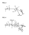
- FIG. 4 is a drawing to show the configuration of a wavelength tunable light source of an external resonator type in a related art.
- a semiconductor laser 1 has one end face 1a subjected to antireflection treatment (for example, AR coating) and emits light from the end face 1a subjected to the AR coating.
- antireflection treatment for example, AR coating
- a lens 2 converts light from the semiconductor laser 1 into a collimated light beam for emission and collects fed-back light (hereinafter, also called return light) on the end face 1a of the semiconductor laser 1 subjected to the AR coating.
- a diffraction grating 3 executes wavelength dispersion of the light from the lens 2 for emission to a mirror 4 and again executes wavelength dispersion of the reflected light from the mirror 4 for emission to the lens 2.
- the mirror 4 selects light of any desired wavelength of diffracted light subjected to the wavelength dispersion in the diffraction grating 3 and reflects the selected light on the diffraction grating 3.
- the mirror 4 rotates on a predetermined point so as to form Littman mounting.
- a beam splitter 5 is provided between the lens 2 and the diffraction grating 3, branches one part of the return light from the diffraction grating 3 for output as output light, and feeds back the other part into the semiconductor laser 1 through the lens 2.
- a beam expander 6 has an anamorphic prism pair (anamorphic prisms 6a and 6b), is provided between the beam splitter 5 and the diffraction grating 3, and shapes the beam shape of the light from the semiconductor laser 1 to a circle for emission to the diffraction grating 3.
- the light subjected to the wavelength selection twice is fed back into the semiconductor laser 1 through the beam expander 6, the beam splitter 5, and the lens 2 and an opposite end face of the semiconductor laser 1 and the mirror 4 form an external resonator for lasing.
- the mirror 4 is rotated, whereby the resonator length and the reflection wavelength also change and stable single-mode oscillation is executed at any desired wavelength.
- the beam splitter 5 branches the light fed back into the semiconductor laser 1 (namely, return light subjected to wavelength selection twice) and outputs a part as output light. Accordingly, laser light extremely high in simplex from which spontaneous emission light generated in the semiconductor laser 1 is removed is output as output light.
- Patent document 1 Japanese Patent Laid-Open No. 198881/1993
- the beam expander 6 is provided between the semiconductor laser 1 and the diffraction grating 3, so that the irradiation width of the diffraction grating in the horizontal direction is improved and the wavelength selectivity becomes high.
- the beam splitter 5 is provided between the semiconductor laser 1 and the diffraction grating 3, so that spontaneous emission light generated in the semiconductor laser 1 can be removed and output light extremely high in simplex can be provided.
- the beam splitter 5 and the anamorphic prisms 6a and 6b of the beam expander 6 are each a refraction medium having a larger refraction index than air (glass, etc.).
- the refraction media 5, 6a, and 6b are provided in the optical path, so that the external resonator length increases, the mode spacing becomes narrow, and the wavelength selectivity worsens; this is a problem.
- Exemplary embodiments of the present invention provide a wavelength tunable light source of an external resonator type for improving wavelength selectivity and efficiently outputting output light.
- the invention according to a first aspect provides a wavelength tunable light source of an external resonator type for selecting a wavelength of light from a semiconductor laser using a diffraction grating, characterized by a prism being provided between the semiconductor laser and the diffraction grating for enlarging the beam shape of the light from the semiconductor laser in the groove arrangement direction of the diffraction grating, emitting the light to the diffraction grating, and reflecting diffracted light from the diffraction grating to provide output light.
- the invention according to the second aspect is characterized by the fact that in the invention according to the first aspect, a mirror for reflecting the diffracted light from the diffraction grating to the diffraction grating is provided, and the prism outputs the output light from between the diffraction grating and the mirror.
- the invention according to the third aspect is characterized by the fact that in the invention according to the second aspect, the prism outputs the output light roughly in parallel with zero-order light of the diffraction grating.
- the invention according to the fourth aspect is characterized by the fact that in the invention according to the first aspect, the prism lessens the incidence angle on the diffraction grating with a temperature rise.
- the invention according to the fifth aspect is characterized by the fact that in the invention according to any of the first to fourth aspects, the light from the semiconductor laser is incident on the prism at Brewster angle.
- the invention according to the sixth aspect is characterized by the fact that in the invention according to any of the first to fifth aspects, the prism is an anamorphic prism.
- the invention provides the following advantages:
- the single prism provided between the semiconductor laser and the diffraction grating performs the beam shaping of the light from the semiconductor laser and reflects a part of the diffracted light from the diffraction grating to provide output light, so that the number of the components of the refraction media in the external resonator can be decreased. Accordingly, an increase in the external resonator length can be lessened, narrowing the mode spacing can be suppressed, and the wavelength selectivity can be enhanced. Further, as the number of the components of the refraction media is decreased, the loss of light power can be suppressed. Therefore, the wavelength selectivity can be improved and the output light can be efficiently output.
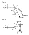
- FIG. 1 is a configuration drawing to show a first embodiment of the invention. Components identical with those in FIG. 4 are denoted by the same reference numerals in FIG. 1 and will not be discussed again.
- a prism 7 is provided in place of the beam splitter 5 and the beam expander 6 in FIG. 4 .
- the prism 7 is a simple anamorphic prism roughly shaped like a wedge and is provided on an optical path of a lens 2 and a diffraction grating 3.
- the refraction index of the prism 7 is higher than that of air; for example, refraction index 1. 6 or more is preferred.
- the prism 7 is glass (crown glass, flint glass, etc.,) a synthetic resin, etc., for example.
- the plane of the prism 7 on which light from a semiconductor laser 1 is incident is an incidence plane 7a and the plane for emitting incidence light from the incidence plane 7a to the diffraction grating 3 (namely, the plane on which return light from the diffraction grating 3 is incident) is an outgoing plane 7b.
- the incidence plane 7a is coated with an antireflection film (for example, AR coating) and the outgoing plane 7b is not coated with an antireflection film or a partial reflection film having any desired reflection factor. If the incidence angle of light incident on the incidence plane 7a from the semiconductor laser 1 is set to Brewster angle, the incidence plane 7a need not be coated with an antireflection film. That is, light from the semiconductor laser 1 is direct polarization and thus the incidence light on the incidence plane 7a from the semiconductor laser 1 is not reflected on the incidence plane 7a and is fully passed through the incidence plane 7a.
- an antireflection film for example, AR coating
- the semiconductor laser 1, the diffraction grating 3, a mirror 4, and the like are disposed so as to form Littman mounting. Since refraction media of the prism 7, the lens 2, etc., exist in an external resonator, the reference position of rotation of the mirror 4 differs from the position in the case where the refraction media do not exist, of course.
- the operation of the device is as follows: Light emitted from one end face (nonreflection end) 1a of the semiconductor laser 1 is converted into a collimated light beam through the lens 2 and the collimated light beam is incident on the prism 7. At this time, the collimated light beam from the lens 2 is incident on the prism 7 without being reflected on the incidence plane 7a of the prism 7.
- the collimated light beam is shaped through the prism 7 (the beam shape is expanded in the horizontal direction) and is emitted from the outgoing plane 7b to the diffraction grating 3. Further, first wavelength dispersion of the shaped light beam is executed by the diffraction grating 3 for emission to the mirror 4. Only light of any desired wavelength is selected on the mirror 4 and is reflected toward the diffraction grating 3, which then again executes wavelength dispersion of the reflected light and wavelength selection for emission to the prism 7.
- the light subjected to the wavelength selection twice is incident on the outgoing plane 7b of the prism 7. At this time, partial return light is reflected on the outgoing plane 7b because of the refractive index difference between the prism 7 and air and most return light is incident on the prism 7 without being reflected on the outgoing plane 7b.
- the return light incident on the prism 7 is emitted from the incidence plane 7a and is fed back into the semiconductor laser 1 through the lens 2 and an opposite end face of the semiconductor laser 1 and the mirror 4 form an external resonator for lasing.
- the mirror 4 is rotated, whereby the resonator length and the reflection wavelength also change and stable single-mode oscillation is executed at any desired wavelength.
- the light reflected on the outgoing plane 7b of the prism 7, of the return light from the diffraction grating 3 is taken out as output light and is output.
- the zero-order light is based on the light incident on the diffraction grating 3 from the prism 7.
- the single prism 7 provided between the semiconductor laser 1 and the diffraction grating 3 serves as both shaping of collimated light beam and taking out of output light from the second diffracted light, so that the number of the components of the refraction media in the external resonator can be decreased as compared with the device shown in FIG. 4 . Accordingly, an increase in the external resonator length can be lessened, narrowing the mode spacing can be suppressed, and the wavelength selectivity can be enhanced. Further, as the number of the components of the refraction media is decreased, the loss of light power can be suppressed. Therefore, the wavelength selectivity can be improved and the output light can be efficiently output.
- the incidence plane 7a of the prism 7 is coated with an antireflection film, so that the manufacturing cost of the prism 7 can be suppressed. If the incidence angle of light incident on the incidence plane 7a is set to Brewster angle, the incidence plane 7a need not be coated with an antireflection film, so that the manufacturing cost of the prism 7 can be further suppressed.
- a part of the light fed back into the semiconductor laser 1 (namely, the return light subjected to the wavelength selection twice) is reflected on the outgoing plane 7b of the prism 7 to provide output light, so that laser light extremely high in simplex from which spontaneous emission light generated in the semiconductor laser 1 is removed can be output as output light.
- the prism 7 outputs the reflected light on the outgoing plane 7b roughly in parallel with the zero-order light of the diffraction grating 3, so that coupling with an optical fiber (not shown) is facilitated and simplification and miniaturization of the structure can be accomplished.
- FIG. 2 is a configuration drawing to show a second embodiment of the invention; it shows an embodiment for suppressing fluctuation of the selected wavelength if an ambient temperature fluctuates. Components identical with those in FIG. 1 are denoted by the same reference numerals in FIG. 2 and will not be discussed again.
- a prism 8 with the orientation of the prism 7 made opposite is provided in place of the prism 7 in FIG. 1 . That is, in FIG. 1 , the vertical angle formed by the incidence plane 7a and the outgoing plane 7b of the prism 7 is on the side of the diffraction grating 3 with respect to the optical axis; whereas, in FIG. 2 , the vertical angle formed by an incidence plane 8a and an outgoing plane 8b of the prism 8 is provided on the side of a mirror 4.
- the operation of the device is as follows:
- the device is almost similar to the device shown in FIG. 1 in that a semiconductor laser 1 and the mirror 4 form an external resonator for lasing and that beam shaping is performed through the prism 8.
- the difference between the devices will be discussed below:
- a part of return light from a diffraction grating 3 is reflected on the outgoing plane 8b of the prism 8 to provide output light.
- the reflection direction on the outgoing plane 8b (output direction of output light) is the direction of the back of the diffraction grating 3 rather than the direction between the diffraction grating 3 and the mirror 4.
- the diffraction grating 3 expands and the groove pitch of the diffraction grating 3 widens.
- the wavelength selected with the diffraction grating 3 and the mirror 4 shifts to the long wavelength side.
- the refractive index of the prism 8 increases and the refraction angle also increases.
- the incidence angle ⁇ on the diffraction grating 3 from the prism 8 lessens.
- the wavelength selected with the diffraction grating 3 and the mirror 4 shifts to the short wavelength side.
- the prism 8 lessens the incidence angle ⁇ on the diffraction grating 3 with a rise in the temperature, so that the wavelength shift caused by expansion of the groove pitch of the diffraction grating 3 can be compensated for. Accordingly, if the ambient temperature fluctuates, the fluctuation of the selected wavelength can be suppressed.
- the material of the prism 7 or the incidence angle may be changed.
- the refractive index of the prism 7 is increased (for example, to 1.6 or more).
- the outgoing plane 7b may be coated with a partial reflection film.
Landscapes
- Physics & Mathematics (AREA)
- Condensed Matter Physics & Semiconductors (AREA)
- General Physics & Mathematics (AREA)
- Electromagnetism (AREA)
- Optics & Photonics (AREA)
- Semiconductor Lasers (AREA)
Abstract
An improvement is made to a wavelength tunable light source of an external resonator type for selecting a wavelength of light from a semiconductor laser (1) using a diffraction grating (3). The device has a prism (6,7,8) provided between the semiconductor laser (1) and the diffraction grating (3) for enlarging the beam shape of the light from the semiconductor laser (1) in the groove arrangement direction of the diffraction grating (3), emitting the light to the diffraction grating, and reflecting diffracted light from the diffraction grating to provide output light.
Description
- This application claims priority to Japanese Patent Application No.
2007-186400, filed July 18, 2007 2007-186400 - The present disclosure relates to a wavelength tunable light source of an external resonator type for selecting a wavelength of light from a semiconductor laser using a diffraction grating (for example, Littrow mounting, Littman mounting, etc.,). More particularly, the present disclosure relates to a wavelength tunable light source of an external resonator type for improving wavelength selectivity and efficiently outputting output light.
- A wavelength tunable light source of an external resonator type executes wavelength dispersion and wavelength selection of light from a semiconductor laser with a diffraction grating and feeds the light whose wavelength is selected into the semiconductor laser for lasing at any desired wavelength. The wavelength tunable light source of the external resonator type includes a wavelength tunable light source of Littrow mounting, a wavelength tunable light source of Littman mounting, etc., for example.
- A far field pattern of light emitted from a semiconductor laser is an elliptical collimated light beam and is a beam shape short relative to the groove arrangement direction of a diffraction grating (wavelength dispersion direction, hereinafter called horizontal direction) and long relative to the groove direction.
- On the other hand, the larger the light irradiation width in the horizontal direction of the diffraction grating (the larger the number of grooves irradiated with light), the larger the wavelength dispersion of the diffraction grating and the higher the wavelength selectivity. Then, the beam shape of light emitted from the semiconductor laser is shaped from an ellipse to a circle for improving the wavelength selectivity of the diffraction grating.
-
FIG. 4 is a drawing to show the configuration of a wavelength tunable light source of an external resonator type in a related art. (For example, refer topatent document 1.) InFIG. 4 , asemiconductor laser 1 has oneend face 1a subjected to antireflection treatment (for example, AR coating) and emits light from theend face 1a subjected to the AR coating. - A
lens 2 converts light from thesemiconductor laser 1 into a collimated light beam for emission and collects fed-back light (hereinafter, also called return light) on theend face 1a of thesemiconductor laser 1 subjected to the AR coating. - A diffraction grating 3 executes wavelength dispersion of the light from the
lens 2 for emission to amirror 4 and again executes wavelength dispersion of the reflected light from themirror 4 for emission to thelens 2. - The
mirror 4 selects light of any desired wavelength of diffracted light subjected to the wavelength dispersion in the diffraction grating 3 and reflects the selected light on the diffraction grating 3. Themirror 4 rotates on a predetermined point so as to form Littman mounting. - A
beam splitter 5 is provided between thelens 2 and the diffraction grating 3, branches one part of the return light from the diffraction grating 3 for output as output light, and feeds back the other part into thesemiconductor laser 1 through thelens 2. - A
beam expander 6 has an anamorphic prism pair (anamorphic prisms beam splitter 5 and the diffraction grating 3, and shapes the beam shape of the light from thesemiconductor laser 1 to a circle for emission to thediffraction grating 3. - The operation of the device is as follows:
- Light emitted from the one
end face 1a of thesemiconductor laser 1 is converted into a collimated light beam through thelens 2 and the collimated light beam passes through thebeam splitter 5 and is shaped by the beam expander 6 (the beam shape is expanded in the horizontal direction). Wavelength dispersion of the shaped light beam is executed by the diffraction grating 3 for emission to themirror 4. Only light of any desired wavelength is reflected on themirror 4 toward the diffraction grating 3, which then again executes wavelength selection of the reflected light. - The light subjected to the wavelength selection twice is fed back into the
semiconductor laser 1 through the beam expander 6, thebeam splitter 5, and thelens 2 and an opposite end face of thesemiconductor laser 1 and themirror 4 form an external resonator for lasing. Themirror 4 is rotated, whereby the resonator length and the reflection wavelength also change and stable single-mode oscillation is executed at any desired wavelength. - Further, the beam splitter 5 branches the light fed back into the semiconductor laser 1 (namely, return light subjected to wavelength selection twice) and outputs a part as output light. Accordingly, laser light extremely high in simplex from which spontaneous emission light generated in the
semiconductor laser 1 is removed is output as output light. - [Patent document 1] Japanese Patent Laid-Open No.
198881/1993 - Thus, the
beam expander 6 is provided between thesemiconductor laser 1 and the diffraction grating 3, so that the irradiation width of the diffraction grating in the horizontal direction is improved and the wavelength selectivity becomes high. Thebeam splitter 5 is provided between thesemiconductor laser 1 and thediffraction grating 3, so that spontaneous emission light generated in thesemiconductor laser 1 can be removed and output light extremely high in simplex can be provided. - However, the
beam splitter 5 and theanamorphic prisms beam expander 6 are each a refraction medium having a larger refraction index than air (glass, etc.). Thus, therefraction media - Since the number of components on the optical path in the external resonator increases, the loss of light power in the external resonator grows and the efficiency of the light power is impaired; this is also a problem.
- Exemplary embodiments of the present invention provide a wavelength tunable light source of an external resonator type for improving wavelength selectivity and efficiently outputting output light.
- The invention according to a first aspect provides a wavelength tunable light source of an external resonator type for selecting a wavelength of light from a semiconductor laser using a diffraction grating, characterized by a prism being provided between the semiconductor laser and the diffraction grating for enlarging the beam shape of the light from the semiconductor laser in the groove arrangement direction of the diffraction grating, emitting the light to the diffraction grating, and reflecting diffracted light from the diffraction grating to provide output light.
The invention according to the second aspect is characterized by the fact that in the invention according to the first aspect, a mirror for reflecting the diffracted light from the diffraction grating to the diffraction grating is provided, and
the prism outputs the output light from between the diffraction grating and the mirror.
The invention according to the third aspect is characterized by the fact that in the invention according to the second aspect, the prism outputs the output light roughly in parallel with zero-order light of the diffraction grating.
The invention according to the fourth aspect is characterized by the fact that in the invention according to the first aspect, the prism lessens the incidence angle on the diffraction grating with a temperature rise.
The invention according to the fifth aspect is characterized by the fact that in the invention according to any of the first to fourth aspects, the light from the semiconductor laser is incident on the prism at Brewster angle.
The invention according to the sixth aspect is characterized by the fact that in the invention according to any of the first to fifth aspects, the prism is an anamorphic prism. - The invention provides the following advantages:
The single prism provided between the semiconductor laser and the diffraction grating (on the optical path in the external resonator) performs the beam shaping of the light from the semiconductor laser and reflects a part of the diffracted light from the diffraction grating to provide output light, so that the number of the components of the refraction media in the external resonator can be decreased. Accordingly, an increase in the external resonator length can be lessened, narrowing the mode spacing can be suppressed, and the wavelength selectivity can be enhanced. Further, as the number of the components of the refraction media is decreased, the loss of light power can be suppressed. Therefore, the wavelength selectivity can be improved and the output light can be efficiently output.
Other features and advantages may be apparent from the following detailed description, the accompanying drawings and the claims. - In the accompanying drawings:
-
FIG. 1 is a configuration drawing to show a first embodiment of the invention; -
FIG. 2 is a configuration drawing to show a second embodiment of the invention; -
FIG. 3 is a configuration drawing to show a third embodiment of the invention; and -
FIG. 4 is a drawing to show the configuration of a wavelength tunable light source of an external resonator type in a related art. - An embodiment of the invention will be discussed with the accompanying drawing.
-
FIG. 1 is a configuration drawing to show a first embodiment of the invention. Components identical with those inFIG. 4 are denoted by the same reference numerals inFIG. 1 and will not be discussed again. InFIG. 1 , aprism 7 is provided in place of thebeam splitter 5 and the beam expander 6 inFIG. 4 .
Theprism 7 is a simple anamorphic prism roughly shaped like a wedge and is provided on an optical path of alens 2 and a diffraction grating 3. The refraction index of theprism 7 is higher than that of air; for example,refraction index 1. 6 or more is preferred. Theprism 7 is glass (crown glass, flint glass, etc.,) a synthetic resin, etc., for example. - The plane of the
prism 7 on which light from asemiconductor laser 1 is incident is anincidence plane 7a and the plane for emitting incidence light from theincidence plane 7a to the diffraction grating 3 (namely, the plane on which return light from thediffraction grating 3 is incident) is anoutgoing plane 7b. - The
incidence plane 7a is coated with an antireflection film (for example, AR coating) and theoutgoing plane 7b is not coated with an antireflection film or a partial reflection film having any desired reflection factor. If the incidence angle of light incident on theincidence plane 7a from thesemiconductor laser 1 is set to Brewster angle, theincidence plane 7a need not be coated with an antireflection film. That is, light from thesemiconductor laser 1 is direct polarization and thus the incidence light on theincidence plane 7a from thesemiconductor laser 1 is not reflected on theincidence plane 7a and is fully passed through theincidence plane 7a. - The
semiconductor laser 1, thediffraction grating 3, amirror 4, and the like are disposed so as to form Littman mounting. Since refraction media of theprism 7, thelens 2, etc., exist in an external resonator, the reference position of rotation of themirror 4 differs from the position in the case where the refraction media do not exist, of course. - The operation of the device is as follows:
Light emitted from one end face (nonreflection end) 1a of thesemiconductor laser 1 is converted into a collimated light beam through thelens 2 and the collimated light beam is incident on theprism 7. At this time, the collimated light beam from thelens 2 is incident on theprism 7 without being reflected on theincidence plane 7a of theprism 7. - The collimated light beam is shaped through the prism 7 (the beam shape is expanded in the horizontal direction) and is emitted from the
outgoing plane 7b to thediffraction grating 3. Further, first wavelength dispersion of the shaped light beam is executed by thediffraction grating 3 for emission to themirror 4. Only light of any desired wavelength is selected on themirror 4 and is reflected toward thediffraction grating 3, which then again executes wavelength dispersion of the reflected light and wavelength selection for emission to theprism 7. - The light subjected to the wavelength selection twice is incident on the
outgoing plane 7b of theprism 7. At this time, partial return light is reflected on theoutgoing plane 7b because of the refractive index difference between theprism 7 and air and most return light is incident on theprism 7 without being reflected on theoutgoing plane 7b. - The return light incident on the
prism 7 is emitted from theincidence plane 7a and is fed back into thesemiconductor laser 1 through thelens 2 and an opposite end face of thesemiconductor laser 1 and themirror 4 form an external resonator for lasing. Themirror 4 is rotated, whereby the resonator length and the reflection wavelength also change and stable single-mode oscillation is executed at any desired wavelength. - On the other hand, the light reflected on the
outgoing plane 7b of theprism 7, of the return light from thediffraction grating 3 is taken out as output light and is output. At this time, it is advisable to set theoutgoing plane 7b of theprism 7 so that the output light is output roughly in parallel with zero-order light in the diffraction grating 3 (the optical axis of the zero-order light and the optical axis of the reflected light on theprism 7 are parallel). There are two types of zero-order light of thediffraction grating 3, namely, zero-order light based on the light incident on thediffraction grating 3 from theprism 7 and zero-order light based on the reflected light on themirror 4. Here, the zero-order light is based on the light incident on thediffraction grating 3 from theprism 7. - Thus, the
single prism 7 provided between thesemiconductor laser 1 and thediffraction grating 3 serves as both shaping of collimated light beam and taking out of output light from the second diffracted light, so that the number of the components of the refraction media in the external resonator can be decreased as compared with the device shown inFIG. 4 . Accordingly, an increase in the external resonator length can be lessened, narrowing the mode spacing can be suppressed, and the wavelength selectivity can be enhanced. Further, as the number of the components of the refraction media is decreased, the loss of light power can be suppressed.
Therefore, the wavelength selectivity can be improved and the output light can be efficiently output. - Since the number of the components can be decreased as compared with the device shown in
FIG. 4 , cost reduction and miniaturization can be accomplished. Further, parallel plane portions among the portions are eliminated and the effects of interference and stray light caused by multiple reflection can be suppressed. - Only the
incidence plane 7a of theprism 7 is coated with an antireflection film, so that the manufacturing cost of theprism 7 can be suppressed. If the incidence angle of light incident on theincidence plane 7a is set to Brewster angle, theincidence plane 7a need not be coated with an antireflection film, so that the manufacturing cost of theprism 7 can be further suppressed. - A part of the light fed back into the semiconductor laser 1 (namely, the return light subjected to the wavelength selection twice) is reflected on the
outgoing plane 7b of theprism 7 to provide output light, so that laser light extremely high in simplex from which spontaneous emission light generated in thesemiconductor laser 1 is removed can be output as output light. - For example, to also use zero-order light of the
diffraction grating 3 as output light for monitor of light power of the wavelength tunable light source, etc., theprism 7 outputs the reflected light on theoutgoing plane 7b roughly in parallel with the zero-order light of thediffraction grating 3, so that coupling with an optical fiber (not shown) is facilitated and simplification and miniaturization of the structure can be accomplished. - An embodiment of the invention will be discussed with the accompanying drawing.
-
FIG. 2 is a configuration drawing to show a second embodiment of the invention; it shows an embodiment for suppressing fluctuation of the selected wavelength if an ambient temperature fluctuates. Components identical with those inFIG. 1 are denoted by the same reference numerals inFIG. 2 and will not be discussed again. - In
FIG. 2 , aprism 8 with the orientation of theprism 7 made opposite is provided in place of theprism 7 inFIG. 1 . That is, inFIG. 1 , the vertical angle formed by theincidence plane 7a and theoutgoing plane 7b of theprism 7 is on the side of thediffraction grating 3 with respect to the optical axis; whereas, inFIG. 2 , the vertical angle formed by anincidence plane 8a and anoutgoing plane 8b of theprism 8 is provided on the side of amirror 4. - The operation of the device is as follows:
The device is almost similar to the device shown inFIG. 1 in that asemiconductor laser 1 and themirror 4 form an external resonator for lasing and that beam shaping is performed through theprism 8. The difference between the devices will be discussed below: - A part of return light from a
diffraction grating 3 is reflected on theoutgoing plane 8b of theprism 8 to provide output light. The reflection direction on theoutgoing plane 8b (output direction of output light) is the direction of the back of thediffraction grating 3 rather than the direction between thediffraction grating 3 and themirror 4. - Subsequently, the case where an ambient temperature fluctuates will be discussed.
The relation of wavelength dispersion of light incident on thediffraction grating 3 is represented by the following expression (1): -

- The parameters are as follows:
- α: Incidence angle on
diffraction grating 3 fromprism 8 - β: Outgoing angle from
diffraction grating 3 - N: Number of slits per mm (namely, number of grooves of
diffraction grating 3 and reciprocal of diffraction grating period) - m: Order of diffracted light (m = 0, ±1, ±2, ±3...)
- X: Wavelength
- For example, if the ambient temperature becomes high, the
diffraction grating 3 expands and the groove pitch of thediffraction grating 3 widens. Thus, if the positional relationship between thediffraction grating 3 and themirror 4 does not fluctuate, the wavelength selected with thediffraction grating 3 and themirror 4 shifts to the long wavelength side. - On the other hand, as the ambient temperature rises, the refractive index of the
prism 8 increases and the refraction angle also increases. Thus, the incidence angle α on thediffraction grating 3 from theprism 8 lessens. Thus, if the positional relationship between thediffraction grating 3 and themirror 4 does not fluctuate, the wavelength selected with thediffraction grating 3 and themirror 4 shifts to the short wavelength side. - That is, the
prism 8 lessens the incidence angle α on thediffraction grating 3 with a rise in the temperature, so that the wavelength shift caused by expansion of the groove pitch of thediffraction grating 3 can be compensated for. Accordingly, if the ambient temperature fluctuates, the fluctuation of the selected wavelength can be suppressed. - The invention is not limited to the embodiments described above and may be the following:
- (1) Although the
outgoing plane 7b of theprism 7 is not provided with an antireflection film or a partial reflection film, the percentage of reflecting return light by theoutgoing plane 7b of theprism 7 is affected by the refractive index difference between theprism 7 and air, the incidence angle of return light on theoutgoing plane 7b, etc. - Therefore, to increase or decrease the percentage of taking out the output light through the
prism 7, the material of theprism 7 or the incidence angle may be changed. For example, to increase the percentage of taking out the output light (to provide higher output light), the refractive index of theprism 7 is increased (for example, to 1.6 or more). To take out large output light, theoutgoing plane 7b may be coated with a partial reflection film. -
- (2) Although the configuration of the wavelength tunable light source of the external resonator type of the Littman mounting has been shown, the invention may be applied to any wavelength tunable light source of an external resonator type for executing wavelength selection using the
diffraction grating 3.FIG. 3 is a configuration drawing to show an example of applying the invention to Littrow mounting. Components identical with those inFIG. 1 are denoted by the same reference numerals inFIG. 3 and will not be discussed again. InFIG. 3 , themirror 4 inFIG. 1 is removed and adiffraction grating 3 rotates and moves. The incidence angle on thediffraction grating 3 is set so that light of any desired wavelength, of diffracted light of thediffraction grating 3 is fed back into asemiconductor laser 1.
Claims (8)
- A wavelength tunable light source of an external resonator type comprises:a semiconductor laser for emitting a light;a diffraction grating for selecting a wavelength of the light from the semiconductor laser; anda prism being provided between the semiconductor laser and the diffraction grating for enlarging a beam shape of the light from the semiconductor laser in a groove arrangement direction of the diffraction grating, emitting the light to the diffraction grating, and reflecting a diffracted light from the diffraction grating to provide an output light.
- The wavelength tunable light source of the external resonator type as claimed in claim 1 further comprising:a mirror for reflecting the diffracted light from the diffraction grating to the diffraction grating,wherein said prism outputs the output light from between the diffraction grating and the mirror.
- The wavelength tunable light source of the external resonator type as claimed in claim 2 wherein said prism outputs the output light roughly in parallel with zero-order light of the diffraction grating.
- The wavelength tunable light source of the external resonator type as claimed in claim 1 wherein said prism lessens the incidence angle on the diffraction grating with a temperature rise.
- The wavelength tunable light source of the external resonator type as claimed in any of claims 1 to 4 wherein the light from the semiconductor laser is incident on said prism at Brewster angle.
- The wavelength tunable light source of the external resonator type as claimed in any of claims 1 to 5 wherein said prism is an anamorphic prism.
- The wavelength tunable light source of the external resonator type as claimed in claim 1 wherein an incidence plane of the prism on which the light from the semiconductor laser is incident is coated with an antireflection film.
- The wavelength tunable light source of the external resonator type as claimed in claim 1 wherein an outgoing plane of the prism from which the light is emitted to the diffraction grating is coated with a partial reflection film.
Applications Claiming Priority (1)
| Application Number | Priority Date | Filing Date | Title |
|---|---|---|---|
| JP2007186400A JP4947367B2 (en) | 2007-07-18 | 2007-07-18 | External resonator type tunable light source |
Publications (1)
| Publication Number | Publication Date |
|---|---|
| EP2017929A2 true EP2017929A2 (en) | 2009-01-21 |
Family
ID=39832295
Family Applications (1)
| Application Number | Title | Priority Date | Filing Date |
|---|---|---|---|
| EP08011376A Withdrawn EP2017929A2 (en) | 2007-07-18 | 2008-06-23 | Wavelength tunable light source of external resonator type |
Country Status (3)
| Country | Link |
|---|---|
| US (1) | US20090022184A1 (en) |
| EP (1) | EP2017929A2 (en) |
| JP (1) | JP4947367B2 (en) |
Cited By (2)
| Publication number | Priority date | Publication date | Assignee | Title |
|---|---|---|---|---|
| CN105655870A (en) * | 2015-12-11 | 2016-06-08 | 中国人民解放军国防科学技术大学 | Tunable-grating external cavity semiconductor laser based on prism beam expanding |
| CN113615014A (en) * | 2019-03-29 | 2021-11-05 | 三菱电机株式会社 | Semiconductor laser device |
Families Citing this family (8)
| Publication number | Priority date | Publication date | Assignee | Title |
|---|---|---|---|---|
| JP5300543B2 (en) | 2009-03-17 | 2013-09-25 | 株式会社ディスコ | Optical system and laser processing apparatus |
| JP6391904B2 (en) * | 2011-11-11 | 2018-09-19 | ソニー株式会社 | Semiconductor laser device assembly |
| JP6273089B2 (en) * | 2012-12-27 | 2018-01-31 | ソニー株式会社 | LASER INJECTION DEVICE AND METHOD FOR MANUFACTURING LASER INJECTION DEVICE |
| JP6182988B2 (en) * | 2013-06-12 | 2017-08-23 | 住友電気工業株式会社 | Spectroscopic device and wavelength selective switch |
| US9563073B2 (en) | 2014-06-27 | 2017-02-07 | Lumentum Operations Llc | Combined splitter, isolator and spot-size converter |
| WO2017127526A1 (en) * | 2016-01-20 | 2017-07-27 | TeraDiode, Inc. | Wavelength beam combining laser systems utilizing prisms for beam quality improvement and bandwidth reduction |
| CN112271550A (en) * | 2020-10-20 | 2021-01-26 | 北京凯普林光电科技股份有限公司 | A wavelength-locked semiconductor laser |
| CN117572650A (en) * | 2023-11-06 | 2024-02-20 | 武汉光迅科技股份有限公司 | Adjustable plane grating filter |
Citations (1)
| Publication number | Priority date | Publication date | Assignee | Title |
|---|---|---|---|---|
| JP2007186400A (en) | 2006-01-11 | 2007-07-26 | Daisuke Maeda | Lightweight material containing low-pressure voids |
Family Cites Families (11)
| Publication number | Priority date | Publication date | Assignee | Title |
|---|---|---|---|---|
| JPH0216782A (en) * | 1988-07-04 | 1990-01-19 | Toshiba Corp | Narrow band laser device |
| JPH0426174A (en) * | 1990-05-22 | 1992-01-29 | Toshiba Corp | Narrow-band laser apparatus |
| US5177750A (en) * | 1991-07-30 | 1993-01-05 | Hewlett-Packard Company | Misalignment-tolerant, grating-tuned external-cavity laser with enhanced longitudinal mode selectivity |
| GB9127241D0 (en) * | 1991-12-23 | 1992-02-19 | Crosfield Electronics Ltd | Light deflecting device |
| JP3713987B2 (en) * | 1998-11-25 | 2005-11-09 | 横河電機株式会社 | External cavity light source |
| US6801560B2 (en) * | 1999-05-10 | 2004-10-05 | Cymer, Inc. | Line selected F2 two chamber laser system |
| US6693745B1 (en) * | 1999-09-14 | 2004-02-17 | Corning Incorporated | Athermal and high throughput gratings |
| US6556297B1 (en) * | 2000-06-02 | 2003-04-29 | Digital Lightwave, Inc. | Athermalization and pressure desensitization of diffraction grating based spectrometer devices |
| US6608847B2 (en) * | 2001-09-28 | 2003-08-19 | New Focus, Inc. | Tunable laser with suppression of spontaneous emission |
| JP4238600B2 (en) * | 2003-02-28 | 2009-03-18 | 日立電線株式会社 | Demultiplexer and wavelength division multiplexing optical transmission module |
| US7257288B1 (en) * | 2004-04-23 | 2007-08-14 | Nistica, Inc. | Tunable optical routing systems |
-
2007
- 2007-07-18 JP JP2007186400A patent/JP4947367B2/en not_active Expired - Fee Related
-
2008
- 2008-06-23 EP EP08011376A patent/EP2017929A2/en not_active Withdrawn
- 2008-06-26 US US12/146,592 patent/US20090022184A1/en not_active Abandoned
Patent Citations (1)
| Publication number | Priority date | Publication date | Assignee | Title |
|---|---|---|---|---|
| JP2007186400A (en) | 2006-01-11 | 2007-07-26 | Daisuke Maeda | Lightweight material containing low-pressure voids |
Cited By (3)
| Publication number | Priority date | Publication date | Assignee | Title |
|---|---|---|---|---|
| CN105655870A (en) * | 2015-12-11 | 2016-06-08 | 中国人民解放军国防科学技术大学 | Tunable-grating external cavity semiconductor laser based on prism beam expanding |
| CN113615014A (en) * | 2019-03-29 | 2021-11-05 | 三菱电机株式会社 | Semiconductor laser device |
| CN113615014B (en) * | 2019-03-29 | 2023-12-08 | 三菱电机株式会社 | Semiconductor laser device |
Also Published As
| Publication number | Publication date |
|---|---|
| US20090022184A1 (en) | 2009-01-22 |
| JP4947367B2 (en) | 2012-06-06 |
| JP2009026834A (en) | 2009-02-05 |
Similar Documents
| Publication | Publication Date | Title |
|---|---|---|
| US20090022184A1 (en) | Wavelength tunable light source of external resonator type | |
| JP7053993B2 (en) | Light source device | |
| US20060256832A1 (en) | Chirped bragg grating elements | |
| JPWO2017022142A1 (en) | Semiconductor laser device | |
| US6700904B2 (en) | Light source for an external cavity laser | |
| JP2017204530A (en) | External cavity semiconductor laser device | |
| CN100355163C (en) | resonator | |
| US6690709B2 (en) | Device and method for reduction of spontaneous emission from external cavity lasers | |
| JP5228616B2 (en) | Tunable light source | |
| JP2015056469A (en) | Diode laser module wavelength controlled by external resonator | |
| JP7457723B2 (en) | External cavity laser device, corresponding system and method | |
| CN103814488B (en) | A kind of outside cavity gas laser | |
| JP6223650B1 (en) | Laser oscillator | |
| JP4402030B2 (en) | External cavity semiconductor laser | |
| JP2011018779A (en) | Wavelength variable light source | |
| JP2008071798A (en) | Laser light source device | |
| US20050094681A1 (en) | Tunable laser source | |
| JP2004511914A (en) | Tunable single mode laser device | |
| JP2007234916A (en) | Tunable laser source and method for adjusting its parameter | |
| JPH03116992A (en) | Semiconductor laser device | |
| JP2006269990A (en) | External resonance semiconductor laser | |
| JP2001156393A (en) | V-groove grating mirror and external resonator type variable wavelength light source using it | |
| US20240396307A1 (en) | Spectral-based correction of laser bar smile | |
| WO2023021675A1 (en) | Semiconductor laser device and illumination device | |
| CN121620843A (en) | Laser apparatus |
Legal Events
| Date | Code | Title | Description |
|---|---|---|---|
| PUAI | Public reference made under article 153(3) epc to a published international application that has entered the european phase |
Free format text: ORIGINAL CODE: 0009012 |
|
| AK | Designated contracting states |
Kind code of ref document: A2 Designated state(s): AT BE BG CH CY CZ DE DK EE ES FI FR GB GR HR HU IE IS IT LI LT LU LV MC MT NL NO PL PT RO SE SI SK TR |
|
| AX | Request for extension of the european patent |
Extension state: AL BA MK RS |
|
| STAA | Information on the status of an ep patent application or granted ep patent |
Free format text: STATUS: THE APPLICATION IS DEEMED TO BE WITHDRAWN |
|
| 18D | Application deemed to be withdrawn |
Effective date: 20101231 |