EP2017755B1 - Design support system for a heat convection field - Google Patents
Design support system for a heat convection field Download PDFInfo
- Publication number
- EP2017755B1 EP2017755B1 EP06731757.8A EP06731757A EP2017755B1 EP 2017755 B1 EP2017755 B1 EP 2017755B1 EP 06731757 A EP06731757 A EP 06731757A EP 2017755 B1 EP2017755 B1 EP 2017755B1
- Authority
- EP
- European Patent Office
- Prior art keywords
- temperature
- designing
- design
- flow rate
- sensitivity
- Prior art date
- Legal status (The legal status is an assumption and is not a legal conclusion. Google has not performed a legal analysis and makes no representation as to the accuracy of the status listed.)
- Active
Links
- 238000013461 design Methods 0.000 title claims description 119
- 238000004458 analytical method Methods 0.000 claims description 60
- 230000035945 sensitivity Effects 0.000 claims description 56
- 238000012546 transfer Methods 0.000 claims description 35
- 230000006870 function Effects 0.000 claims description 34
- 238000000034 method Methods 0.000 claims description 25
- 238000009792 diffusion process Methods 0.000 claims description 17
- 230000004907 flux Effects 0.000 claims description 17
- 238000005457 optimization Methods 0.000 claims description 17
- 238000004378 air conditioning Methods 0.000 claims description 9
- 230000001419 dependent effect Effects 0.000 claims description 5
- 238000007664 blowing Methods 0.000 claims description 4
- 239000011159 matrix material Substances 0.000 claims description 3
- 238000004088 simulation Methods 0.000 description 11
- 238000005192 partition Methods 0.000 description 9
- 238000010438 heat treatment Methods 0.000 description 5
- 238000004364 calculation method Methods 0.000 description 4
- 238000013459 approach Methods 0.000 description 3
- 238000004422 calculation algorithm Methods 0.000 description 2
- 239000003086 colorant Substances 0.000 description 2
- 238000001816 cooling Methods 0.000 description 2
- 239000012530 fluid Substances 0.000 description 2
- 238000009472 formulation Methods 0.000 description 2
- 239000000203 mixture Substances 0.000 description 2
- 238000012545 processing Methods 0.000 description 2
- 238000004590 computer program Methods 0.000 description 1
- 238000007796 conventional method Methods 0.000 description 1
- 230000003247 decreasing effect Effects 0.000 description 1
- 230000000694 effects Effects 0.000 description 1
- 230000007613 environmental effect Effects 0.000 description 1
- 238000002474 experimental method Methods 0.000 description 1
- 230000002349 favourable effect Effects 0.000 description 1
- 239000005357 flat glass Substances 0.000 description 1
- 230000002068 genetic effect Effects 0.000 description 1
- 230000020169 heat generation Effects 0.000 description 1
- 238000005338 heat storage Methods 0.000 description 1
- 238000009413 insulation Methods 0.000 description 1
- 239000012212 insulator Substances 0.000 description 1
- 238000005293 physical law Methods 0.000 description 1
- 238000011160 research Methods 0.000 description 1
- 238000012827 research and development Methods 0.000 description 1
- 230000000007 visual effect Effects 0.000 description 1
- XLYOFNOQVPJJNP-UHFFFAOYSA-N water Substances O XLYOFNOQVPJJNP-UHFFFAOYSA-N 0.000 description 1
Images


Classifications
-
- G—PHYSICS
- G06—COMPUTING; CALCULATING OR COUNTING
- G06F—ELECTRIC DIGITAL DATA PROCESSING
- G06F30/00—Computer-aided design [CAD]
- G06F30/10—Geometric CAD
- G06F30/17—Mechanical parametric or variational design
-
- G—PHYSICS
- G06—COMPUTING; CALCULATING OR COUNTING
- G06F—ELECTRIC DIGITAL DATA PROCESSING
- G06F30/00—Computer-aided design [CAD]
-
- G—PHYSICS
- G06—COMPUTING; CALCULATING OR COUNTING
- G06F—ELECTRIC DIGITAL DATA PROCESSING
- G06F30/00—Computer-aided design [CAD]
- G06F30/20—Design optimisation, verification or simulation
- G06F30/23—Design optimisation, verification or simulation using finite element methods [FEM] or finite difference methods [FDM]
-
- G—PHYSICS
- G06—COMPUTING; CALCULATING OR COUNTING
- G06F—ELECTRIC DIGITAL DATA PROCESSING
- G06F2111/00—Details relating to CAD techniques
- G06F2111/10—Numerical modelling
-
- G—PHYSICS
- G06—COMPUTING; CALCULATING OR COUNTING
- G06F—ELECTRIC DIGITAL DATA PROCESSING
- G06F2119/00—Details relating to the type or aim of the analysis or the optimisation
- G06F2119/08—Thermal analysis or thermal optimisation
Definitions
- the present invention relates to a design support method, a design support system, and a design support program for supporting the design of a heat convection field or a mass diffusion field.
- Design of a heat convection field or a mass diffusion field is required in various sites or uses such as, for example, design of an indoor environment using an air conditioning apparatus, thermal design of electronic devices, and management of exhaust gas concentration in plants.
- a technique of analyzing the influence, of a change in the temperature or the like as a boundary condition, exerted on a minute temperature change or the like of the target position to find a desirable boundary condition has been proposed (see, for example, non-patent documents 1 and 2 specified below).
- a perturbation equation from the convection field which is used as the reference, is introduced and the adjoint formulation to the perturbation equation is derived.
- an adjoint problem and the boundary condition therefor are set.
- changes in various heat transfer characteristics to an arbitrary thermal perturbation and an arbitrary flow perturbation on the boundary are estimated.
- Non-patent document 1 Kazunari MOMOSE et al., Influence of Thermal and Flow Boundary Perturbations on Convection Heat Transfer Characteristics, Journal of The Japan Society of Mechanical Engineers (edition B), June 2000, Vol. 66, No. 646, pp. 215-221
- Non-patent document 2 Kazunari MOMOSE et al., "Influence of Thermal and Flow Boundary Perturbations on Convection Heat Transfer Characteristics: Numerical Analysis Based on Adjoint Formulation", 2002 Wiley Periodicals, Inc., Heat Transfer Asian Research, 32(1): 1-12, 2003; Published online in Wiley InterScience (WWW.interscience. Wiley.com). DOI 10.1002/htj.10065
- metric ⁇ While useful for estimating thermal manageability of a given data center configuration, metric ⁇ only provides limited information regarding the energy efficiency of the system. For example, it is difficult to ascertain whether local hotspots are formed primarily due to poor air conditioner performance, suboptimal equipment layout, unfavorable airflow patterns etc.
- Hung-Chi Lo "A three-dimensional inverse problem in estimating the internal heat flux of housing for high speed motors", Applied Thermal Engineering, Vol. 26, No. 14-15, 7 February 2006, pages 1515-1529 .
- a commercial CFD software is used to implement a 3D inverse method to estimate the heat flux from the motor and the stator of a water cooled high speed motor.
- the method of Huang et al. consists of three separate stages: solving the direct problem, considering the inverse problem and analyzing the steepest descent problem. In the inverse problem the solution obtained from the direct problem is used as a boundary condition and the heat flux is the only unknown parameter.
- the solution of the inverse problem is then found by minimizing a function of the difference between the measured and CFD predicted temperature.
- This method is only capable of solving linear heat conduction problems and cannot be applied to turbulent flows with high nonlinearity. Further, sensitivity can only be analyzed with respect to the heat flux but not with respect to other boundary conditions like for example the change of the overall heat transfer coefficient.
- the present invention made in light of these circumstances has an object of providing a general-purpose and highly convenient design support system for a heat convection field or a mass diffusion field which significantly reduce the number of times of numerical simulation required to examine the designing parameters for achieving the design purpose.
- the present invention realizes general-purpose and highly convenient design support for a heat convection field or a mass diffusion field which significantly reduces the number of times of numerical simulation required to examine the designing parameters for achieving the design purpose.
- numerical analysis is performed with predetermined boundary conditions (initially set values of designing parameters).
- inverse analysis is performed based on adjoint numerical analysis.
- analysis of sensitivity for a design purpose is performed.
- the adjoint numerical analysis the sensitivity to any number of designing variables and any distribution designing variable is obtained by performing a numerical analysis once.
- the result thus obtained is used together with mathematical programming. In this case, an automatic optimization design support system for various devices or various spaces which use heat transfer or mass transfer is realized.
- governing equations of a heat convection field or a mass diffusion field is set as constraints and is formulated as a nonlinear optimization problem for maximizing or minimizing a given objective function (local temperature, uniformity in a given area, deviation from the target value, etc.).
- a given objective function local temperature, uniformity in a given area, deviation from the target value, etc.
- Q is an arbitrary designing space accompanying heat flow and mass diffusion.
- fT, fC, fu and fp are functions regarding the temperature, mass concentration, flow rate and pressure defined in the space Q, and are determined by the design purpose (for example, maximization, minimization, uniformization or the like of the temperature, mass concentration, flow rate and pressure in a given area).
- ⁇ T, ⁇ q, ⁇ C, ⁇ m and ⁇ u are respectively boundaries of the space Q in which the temperature, heat flux, concentration, diffusion flux and flow rate vector are controllable.
- gT, gq, gC, gm and gu are design purposes defined on the respective boundaries (for example, maximization, minimization or the like of the heat transfer amount on the boundary, mass transfer amount on the boundary, or the flow rate on the boundary).
- the boundary condition changes by a minute amount to perform perturbation expansion of the governing equation A in the vicinity of the reference state (for example, in the vicinity of the current designing state).
- the obtained linear perturbation equation system is applied to the first variation of equation (2) and then divided into domain integrals and boundary integrals with Gauss's divergence theorem or the like.
- an adjoint operator matrix A* to the linear perturbation equation system is obtained.
- the adjoint problem the conservation equation of mass, momentum, energy and concentration in an adjoint field having adjoint pressure p*, adjoint flow rate u*, adjoint temperature T* and adjoint concentration C* as dependent variables
- the boundary conditions thereof are selected as follows.
- the change (sensitivity) of the objective function to the changes of all the controllable boundary conditions are found.
- the third term of the right side of equation (5) represents the sensitivity to the change ⁇ K in the overall heat transfer coefficient through the wall, which is not actively controllable but is important in designing. Such sensitivity is usable to evaluate the influence of the structure (heat insulating capability) of the wall, window glass or the like.
- the target area is set to ⁇ D, and the volume thereof is set to VD, and the average temperature in the area before the optimization is set to Tav.
- the objective function is converted into the deviation (on the unit of temperature), instead of the variance, such that an error is perceived intuitively.
- the purpose setting is limited to heat environment for the sake of simplicity.
- a purpose can be derived in a similar manner for mass diffusion, flow rate and pressure from equations (3) and (4).
- maximization, uniformization and the target value realization are mentioned.
- the design purpose may be anything which is a function on the temperature, mass concentration, flow rate or pressure in the designing space or a function on the temperature, thermal flow rate, mass concentration, diffusion flux or flow rate on the boundary of the designing space and is differentiable once for each physical amount. Any such purpose can be appropriately set as required by the designer.
- a design support system 1 includes an input device 10 including a keyboard, a mouse or the like, a computer 11, and a display device 12 including an LCD, a CRT or the like.
- the computer 11 includes a central processing unit 13, a memory device 14 including a hard disc drive or the like, an input reception section 15 for receiving a signal from the input device 10, a memory 16, an image output section 17 for outputting a signal to the display device 12, and a CG processing section 18.
- the specific structure of the design support system 1 is not limited to the above-described structure.
- a design support program is a computer program for allowing the computer 11 to perform the functions described below.
- the computer 11 only needs to be communicable with the input device 10 and the display device 12, and may be connected thereto in a wired or wireless manner.
- the computer 11 may be installed at a different site from the input device 10 or the display device 12. For example, the computer 11 may be connected to a terminal device on the designer side via a network (in a wired or wireless manner).
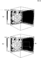
- the design is to be made on an indoor space having nine blowoff outlets (upper blowoff outlets 21 through 23, middle blowoff outlets 31 through 33, and lower blowoff outlets 41 through 43) and one opening 20.
- the temperature at the center of the indoor space is to be maximized.
- Positional information designated at the time of designing is not limited to information on a predetermined point, and may be information on a predetermined area.
- the center of the indoor space is designated as the predetermined point.
- Such a point or area may be designated with a coordinate value (numerical value) using the keyboard or the like.
- a point or area can be designated on a screen by clicking and dragging the mouse for improved convenience. The point or area designated in this manner is graphically displayed in a designing space model as a target 25.
- a designing space model is created.
- the system 1 has a model creation function, and the user (designer) uses the input device 10 (for example, inputs a command to the keyboard or performs an operation on the mouse such as clicking, dragging or the like) to select a menu bar, draw, input a command or the like.
- an arbitrary designing space can be set easily.
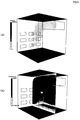
- an indoor space model is set as shown in FIG. 3 .
- nine blowoff outlets (upper blowoff outlets 21 through 23, middle blowoff outlets 31 through 33, and lower blowoff outlets 41 through 43) are formed in one of two walls facing each other, one opening 20 is formed in an upper part of the other wall, and the ceiling and the floor are cooling faces.
- initial values (boundary conditions) of designing parameters are also set when the model is created.
- the designing parameters are, for example, the temperature of the air blown through each blowoff outlet, the blowing direction, the blowing speed, the temperature of the ceiling and the floor, etc.
- the designing parameters may be set by a different step from the creation of the model (step S1).
- the "mesh (M)" button in the menu bar is clicked to automatically generate meshes on the model (step S2).
- the number of meshes may be set to a predetermined value or appropriately set by the user. Namely, the number of meshes may be increased in order to raise the precision of analysis, or may be decreased in order to raise the speed of analysis.
- the design support system 1 may be set to allow the user to select the number of meshes freely.
- FIG. 4 shows an exemplary image shown on the display device during the forward analysis.
- step S4 When the forward analysis is finished and the user clicks the "view (V)" button in the menu bar (see FIG. 6(a) ), the speed distribution and temperature distribution on an arbitrary face of the model are displayed as shown in FIG. 5 (step S4).
- the face to be displayed may be changed easily using the mouse or the like.
- the image of speed distribution (see FIG. 5(a) ) and the image of temperature distribution (see FIG. 5(b) ) may be easily switched to each other.
- the design purpose is first set (step S5).
- the design purpose is to maximize the temperature at the center of the indoor space. Therefore, the above-mentioned target 25 is created at the center of the indoor space (see FIG. 6(a) ), and the object scalar is set to the temperature (see FIG. 6(b) ).
- the target 25 is set small enough to look substantially like a point (see FIG. 6(c) ). In the case where the target 25 is a predetermined area, the target 25 may be set large in the image of FIG. 6(c) . In this example, there is one target 25.
- the design purpose is regarding, for example, the temperature at a plurality of points in the indoor space, a plurality of targets 25 may be set.
- the computer is set to the inverse analysis mode "maximize" and other conditions are also set (in this example, convergence conditions and maximum possible number of time of repetition). Then, the execution/continue button is clicked. Then, as shown in FIG. 7(b) , the inverse analysis is executed (step S6).
- the inverse analysis is finished and the user clicks the "view (V)" button in the menu bar.
- the sensitivity to each parameter (a ratio of change in the design purpose with respect to a change in each design parameter; in this example, in the case where the temperature at the center of the indoor space is to be raised, how much influence is exerted on the temperature at the center of the indoor space by the change in the blowoff temperature or the like) is displayed quantitatively and visually.
- the user may use the keyboard, mouse or the like to arbitrarily switch the images displaying the sensitivity to the parameters.
- FIG. 8(a), FIG. 8(b) , FIG. 9(a), FIG. 9(b) and FIG. 10(a) show the level of sensitivity with the level of color darkness as an example.
- the manner of displaying the sensitivity is not specifically limited, and the level of sensitivity may be displayed with contour lines, colors (e.g., red for a highly sensitive area and blue for a non-sensitive area) or gradation levels.
- the level of sensitivity may be displayed with a graph.
- the system 1 performs the above-described design support operation. Then, the user examines the designing particulars while checking the sensitivity displayed on the screen.
- FIG. 8(a) it is understood that for raising the temperature at the center of the indoor space, it is most efficient to raise the blowoff temperature at the lower left and lower right blowoff outlets 41 and 43 (hereinafter, regarding the reference numerals, see FIG. 3 ) and to lower the blowoff temperature at the upper middle and central outlets 22 and 32.
- FIG. 8(b) it is understood that for raising the temperature at the center of the indoor space, it is preferable to increase the flow rate in the blowoff direction at the lower middle blowoff outlet 42.
- FIG. 9(b) it is understood that it is preferable to increase the flow rate in the vertical direction at the lower middle blowoff outlet 42.
- FIG. 10(a) it is understood that it is preferable to increase the heating amount at the central position in the top-bottom direction of the wall. Accordingly, it is conceivable to, for example, install a heater at this position.
- the sensitivity of the area is displayed on the screen of the display device 12.
- the user for example, drags the mouse to designate a predetermined area R1 on the screen shown in FIG. 10(b)
- a temperature change of the target with respect to a change in the heating amount in the area R1 is displayed on the screen.
- the heating amount in the area R1 is increased by 1 kW
- the temperature of the target is increased by 0.5124°C. Based on this, when a heater is to be installed on the wall, a rough estimate on the heating amount required of the heater can be obtained by designating an area corresponding to the area size of the heater at the position where the heater is to be installed.
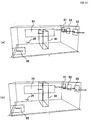
- FIG. 11 (a) and FIG. 11(b) the design is to be made on a rectangular parallelepiped indoor space.
- Three blowoff outlets 51, 52 and 53 are provided on one of two walls facing each other in a longitudinal direction.
- a window 54 is provided on one of two walls perpendicular to the wall having the blowoff outlets.
- An opening 55 is provided on the wall facing the wall having the window 54.
- a partition 60 is provided at the center of the room.
- the partition 60 does not reach the ceiling with a gap being made between the partition 60 and the ceiling.
- the partition 60 reaches the ceiling.
- FIG. 12 through FIG. 17 show the results of numerical analysis performed on each of the above exemplary models in substantially the same manner as described above.
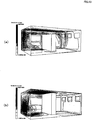
- FIG. 12 (a) and FIG. 12 (b) show the sensitivity to the temperature.
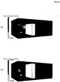
- FIG. 13(a) and FIG. 13(b) show the sensitivity to the heating amount on the wall.
- FIG. 14(a) and FIG. 14(b) show the sensitivity to the air flow in the blowoff direction (X direction) on the wall.
- FIG. 15 (a) and FIG. 15 (b) show the sensitivity to the air flow in the vertical direction (Z direction).
- FIG. 16(a) and FIG. 16(b) show the sensitivity to the overall heat transfer coefficient through the window.
- FIG. 17(a) and FIG. 17(b) show numerical data on the sensitivity to each of the designing parameters.
- the sensitivity to each parameter varies depending on the height of the partition 60.
- the partition 60 (hereinafter, regarding the reference numerals, see FIG. 11(a) and FIG. 11(b) ) does not reach the ceiling as shown in FIG. 12(a)
- the sensitivity to the temperature at the left blowoff outlet 51 is high.
- the partition 60 reaches the ceiling as shown in FIG. 12(b) the sensitivity to the temperature at the left blowoff outlet 51 is low, and the sensitivity to the temperature at the right blowoff outlet 53 is highest.
- the design support method and the design support system 1 can significantly reduce the number of times of numerical simulation required to examine the designing parameters for achieving the design purpose, thus can significantly reduce the load on the computer, and also can significantly reduce the time for the calculation, as compared with the usual design method which is a combination of the numerical simulation (forward analysis) and the optimization algorithm.
- the design purpose is first set and then inverse analysis is performed to find the sensitivity to each of various parameters. Then, the information on the sensitivity is graphically displayed on the display device 12. Therefore, when designing a heat convection field, a guide regarding which parameter(s), and how much of the parameter(s), should be changed can be obtained easily. For example, in the case where the temperature at a predetermined point in the indoor space is to be put to a predetermined level, a specific design guide can be obtained regarding at which blowoff outlet(s), and how much, the temperature should be raised. Thus, a clear design guide can be obtained without relying on the intuition of the designer, unlike in the conventional art.
- the information on the sensitivity is displayed on a three-dimensional model visually and quantitatively. Therefore, the guide for design can be obtained easily and quickly. Specifically, the information on the sensitivity is displayed using color gradation levels, contour lines, different colors or the like. Therefore, the quantitative information on the sensitivity in a three-dimensional space can be grasped at a glance.
- the design guide can be intuitively perceived. This can realize a highly convenient design support.
- a designing space model can be created while referring to a three-dimensional graphic image displayed on the display device 12. This allows the designing space model to be created simply and quickly at the site of design.
- the ability of automatically generating meshes on the model provides a high level of convenience.
- the creation of the model, generation of meshes, forward analysis, setting of a design purpose, inverse analysis and display of sensitivity as a result of the inverse analysis can be executed with only a series of simple operations using the input device 10.
- the design support system 1 in this embodiment has a modeler function, a forward analysis function, a purpose setting function, an inverse analysis function and a sensitivity display function.
- the design support system 1 exhibits superb convenience at the site of design.
- the design purpose is to maximize the temperature at a predetermined point in an indoor space.
- the design purpose may be something else; for example, to minimize the temperature at a predetermined point in an indoor space.
- the design purpose may be to maximize or minimize the flow rate, the mass concentration, or the pressure at a predetermined point in an indoor space.
- the design purpose may be to maximize or minimize the temperature, mass concentration, flow rate or pressure in a predetermined area of a designing space.
- the design purpose may be to maximize or minimize the temperature, heat transfer amount, mass concentration, mass transfer amount, flow rate or pressure at a predetermined point or in a predetermined area on a boundary of a designing space (for example, a wall, a window, etc. which divides the indoor space, window, etc.).
- the design purpose may be to uniformize the temperature in a predetermined area in an indoor space. For example, it may be occasionally desired to uniformize the temperature of an area where there is always somebody present (for example, around the desk in a work office) from the viewpoint of the indoor air conditioning environment. In such a case, the indoor environment is designed to uniformize the temperature in a predetermined area, not to maximize or minimize the temperature at a predetermined point.
- the design support system 1 in this embodiment can support such a design of heat convection field by setting a target area and the temperature so as to uniformize the temperature in a predetermined area.
- the design purpose may be to uniformize the temperature, mass concentration, flow rate or pressure in a predetermined area in a designing space.
- the design purpose may be to uniformize the temperature, heat transfer amount, mass concentration, mass transfer amount, flow rate or pressure in a predetermined area on a boundary of a designing space.
- the design purpose may be to put the temperature at a plurality of points in an indoor space to a respective predetermined level. For example, from the viewpoint of the air conditioning environment of a work office in winter, it may be occasionally desired to make an area where there is always somebody present warm, but to make an area where there are office electronics relatively cool.
- the design support system 1 can set a plurality of targets and set an appropriate temperature to be achieved for each of the targets.
- the design support system 1 can also support a design of heat convection field in such a case.
- the design purpose may be to put the temperature, mass concentration, flow rate or pressure at one or each of a plurality of points or in one or each of a plurality of areas in a designing space to a predetermined level.
- the design purpose may be to put the temperature, heat transfer amount, mass concentration, mass transfer amount, flow rate or pressure at one or each of a plurality of points or in one or each of a plurality of areas on a boundary of a designing space to a predetermined level.
- the temperature at a plurality of points in an indoor space may be actually measured in advance, and the design purpose may be to put the temperature of each of the points to the actually measured value.
- the design support system 1 may be used to identify an unknown designing parameter.
- the amount of heat leaking from the wall can be analyzed, and thus a design of heat insulation conditions of the wall (design of specifications of a heat insulator) or the like can be supported.
- the design purpose may be to put the temperature, mass concentration, flow rate or pressure at one or each of a plurality of points or in one or each of a plurality of areas in a designing space to the actually measured value of the temperature, mass concentration, flow rate or pressure at the respective point or area.
- the design purpose may be to put the temperature, heat transfer amount, mass concentration, mass transfer amount, flow rate or pressure at one or each of a plurality of points or one or each of a plurality of areas on a boundary of a designing space to the actually measured value of the temperature, heat transfer amount, mass concentration, mass transfer amount, flow rate or pressure at the respective point or area.
- the design support method described above is completed when the sensitivity is displayed after inverse analysis (see FIG. 2 ).
- optimization may be performed by, after the inverse analysis, automatically changing the designing variable based on mathematical programming (gradient-type nonlinear optimization) and repeating forward analysis and inverse analysis.
- the design support system 1 may include an optimization function of automatically optimizing a designing parameter for the design purpose.
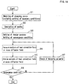
- step S11 the designing space is modeled in step S11, and then meshes are automatically generated in step S12. Then, in step S13, the design purpose and a convergence condition are set. After performing forward analysis in step S14, inverse analysis is performed in step S15. Then, in step S16, it is determined whether the convergence condition has been fulfilled or not. When the convergence condition has not been fulfilled, the value of the designing parameter is changed in step S17, and the forward analysis in step S14 and the inverse analysis in step S15 are repeated. The forward analysis and the inverse analysis are repeated until the convergence condition is fulfilled in step S16. For such an optimization calculation, it is preferable that the user sets the upper limit and the lower limit so that the repeated calculation does not diverge.
- the sensitivity found by the inverse analysis is displayed on the screen as it is.
- a change amount of the designing parameter which is necessary for the required change of the design purpose may be displayed.
- a change amount of the temperature at the blowoff outlet for example, the amount of temperature which needs to be changed in order to raise the temperature of the target by 1°C
- the designing parameter is the temperature on a boundary of an indoor space or the like.
- the designing parameter is not limited to a so-called boundary condition but encompasses the internal heat generation, internal mass diffusion, the shape of the physical object and the like in a designing space or the like.
- the above-described embodiments are applied to air conditioning design in an indoor space.
- the present invention is not limited to air conditioning design, but is applicable to design of any heat convection field or mass diffusion field.
- the present invention is not limited to indoor or outdoor air conditioning design, but is applicable to, for example, internal thermal design of the housing of electronics such as computers and the like, internal environmental design of plants and factories, estimate of the influence of exhaust gas on parking areas, estimate of behavior of the thermal fluid in a heat storage tank, and the like.
- the present invention is useful for, for example, designing various devices or various spaces (environment) using heat or mass transfer.
Description
- The present invention relates to a design support method, a design support system, and a design support program for supporting the design of a heat convection field or a mass diffusion field.
- Design of a heat convection field or a mass diffusion field is required in various sites or uses such as, for example, design of an indoor environment using an air conditioning apparatus, thermal design of electronic devices, and management of exhaust gas concentration in plants.
- Along with the recent increase in the operation speed of computers, numerical simulations of a heat convection field or a mass diffusion field have been put into practice, and some general-purpose heat and fluid flow analysis software and the like have already become commercially available and are used as designing tools. However, such software is generally used to simply obtain a solution to appropriate parameters given by a designer. For the purpose of optimization, such designing parameters are now repeatedly modified in a trial-and-error manner based on the experience of designers. Namely, the solution obtained by a numerical simulation performed once is merely a specific solution to a specific boundary condition (an initial value of a designing parameter). When the boundary condition is changed, the numerical simulation needs to be performed again.
- In the meantime, an inverse problem approach which combines a numerical simulation and mathematical programming to realize automatic optimization is recently a target of attention. Various methods of optimization have been attempted. Such optimization methods are roughly classified into gradient-based optimization methods using numerical derivatives obtained by a finite difference method, and global optimization methods using genetic algorithms or the like. With each group of methods, the required number of times of numerical simulation rapidly increases as the number of designing parameters increases. Therefore, in the case where the number of designing variables is large or infinite (distribution amount), it is difficult to realize optimization within a reasonable amount of time.
- Such a conventional technique of giving a boundary condition and then obtaining the temperature or the like at a target position (hereinafter, referred to as the "forward problem approach") is not practical because the numerical simulation needs to be performed too many times until the design purpose is achieved. For these reasons, there have been no general-purpose design support system easily usable at the site of design.
- A technique of analyzing the influence, of a change in the temperature or the like as a boundary condition, exerted on a minute temperature change or the like of the target position to find a desirable boundary condition (hereinafter, referred to as the "inverse problem approach") has been proposed (see, for example, non-patent
documents non-patent documents - Non-patent document 1: Kazunari MOMOSE et al., Influence of Thermal and Flow Boundary Perturbations on Convection Heat Transfer Characteristics, Journal of The Japan Society of Mechanical Engineers (edition B), June 2000, Vol. 66, No. 646, pp. 215-221
- Non-patent document 2: Kazunari MOMOSE et al., "Influence of Thermal and Flow Boundary Perturbations on Convection Heat Transfer Characteristics: Numerical Analysis Based on Adjoint Formulation", 2002 Wiley Periodicals, Inc., Heat Transfer Asian Research, 32(1): 1-12, 2003; Published online in Wiley InterScience (WWW.interscience. Wiley.com). DOI 10.1002/htj.10065
- In Schmidt, R. et al.: "Challenges of data center thermal management", IBM Journal of Research and Development, Vol. 49, 1 September 2005, 709-723, many of the challenges faced in data center cooling designs are captured. Schmidt, R. et al. argue that a data center with favorable global profiles (low supply heat index SHI and high return heat index RHI) can still be subjected to local hotspots that hinder adequate thermal management. To address this concern, the following metric was proposed:

- A value of β = 0 indicates that no hot air is recirculated to the front of the rack, while a value of β = 1 implies insufficient cold air supply so that air from the hot aisle is directly recirculated back to the inlet of the rack. While useful for estimating thermal manageability of a given data center configuration, metric β only provides limited information regarding the energy efficiency of the system. For example, it is difficult to ascertain whether local hotspots are formed primarily due to poor air conditioner performance, suboptimal equipment layout, unfavorable airflow patterns etc.
- It is often difficult to access the internal part of an electrical machine to measure the heat flux and temperatures. To overcome this problem in Cheng-Hung Huang, Hung-Chi Lo: "A three-dimensional inverse problem in estimating the internal heat flux of housing for high speed motors", Applied Thermal Engineering, Vol. 26, No. 14-15, 7 February 2006, pages 1515-1529, a commercial CFD software is used to implement a 3D inverse method to estimate the heat flux from the motor and the stator of a water cooled high speed motor. The method of Huang et al. consists of three separate stages: solving the direct problem, considering the inverse problem and analyzing the steepest descent problem. In the inverse problem the solution obtained from the direct problem is used as a boundary condition and the heat flux is the only unknown parameter. The solution of the inverse problem is then found by minimizing a function of the difference between the measured and CFD predicted temperature. This method is only capable of solving linear heat conduction problems and cannot be applied to turbulent flows with high nonlinearity. Further, sensitivity can only be analyzed with respect to the heat flux but not with respect to other boundary conditions like for example the change of the overall heat transfer coefficient.
- As described above, methods which utilize the numerical analysis of adjoint problems have been studied. These methods have been merely of the level of investigative experiment based on simple models, and a general-purpose and highly convenient design support system usable in actual sites of design has not been existent.
- The present invention made in light of these circumstances has an object of providing a general-purpose and highly convenient design support system for a heat convection field or a mass diffusion field which significantly reduce the number of times of numerical simulation required to examine the designing parameters for achieving the design purpose.
- The above object is achieved by a design support system having the features of
independent claim 1. Further advantageous embodiments of the design support method according to the invention are given independent claims 2 to 7. - The present invention realizes general-purpose and highly convenient design support for a heat convection field or a mass diffusion field which significantly reduces the number of times of numerical simulation required to examine the designing parameters for achieving the design purpose.
-
- [
FIG. 1] FIG. 1 is a structural view of a design support system according to an embodiment. - [
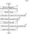
FIG. 2] FIG. 2 is a flowchart showing a part of a method for designing an indoor environment. - [
FIG. 3] FIG. 3 shows an examples of image display representing an example of analytical model. - [
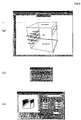
FIG. 4] FIG. 4 is an example of image display of forward analysis. - [
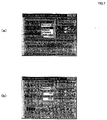
FIG. 5 ] (a) and (b) are examples of image display representing results of forward analysis. - [
FIG. 6 ] (a) through (c) are examples of image display representing the purpose setting of inverse analysis. - [
FIG. 7 ] (a) and (b) are examples of image display representing inverse analysis. - [
FIG. 8 ] (a) and (b) are examples of image display representing sensitivity. - [
FIG. 9 ] (a) and (b) are examples of image display representing sensitivity. - [
FIG. 10 ] (a) and (b) are examples of image display representing sensitivity. - [
FIG. 11 ] (a) and (b) are examples of image display representing another example of analytical model. - [
FIG. 12 ] (a) and (b) are examples of image display representing sensitivity to the temperature. - [
FIG. 13 ] (a) and (b) are examples of image display representing sensitivity to heat. - [
FIG. 14 ] (a) and (b) are examples of image display representing sensitivity to the air flow in the X direction. - [
FIG. 15 ] (a) and (b) are examples of image display representing sensitivity to the air flow in the Z direction. - [
FIG. 16 ] (a) and (b) are examples of image display representing sensitivity to the overall heat transfer coefficient. - [
FIG. 17 ] (a) and (b) are tables showing calculation results of inverse analysis. - [
FIG. 18] FIG. 18 is a flowchart of automatic optimization design of an indoor environment. -
- 1
- Design support system
- 10
- Input device
- 11
- Computer
- 12
- Display device
- 25
- Target
- Hereinafter, embodiments of the present invention will be described in detail with reference to the drawings.
- In one embodiment according to the present invention, numerical analysis (forward analysis) is performed with predetermined boundary conditions (initially set values of designing parameters). Using the results of the forward analysis, inverse analysis is performed based on adjoint numerical analysis. In this way, analysis of sensitivity for a design purpose is performed. (With the adjoint numerical analysis, the sensitivity to any number of designing variables and any distribution designing variable is obtained by performing a numerical analysis once.) As a result, a quantitative and visual guide on how to improve the design is obtained. In another embodiment, the result thus obtained is used together with mathematical programming. In this case, an automatic optimization design support system for various devices or various spaces which use heat transfer or mass transfer is realized.
- In one embodiment according to the present invention, governing equations of a heat convection field or a mass diffusion field (conservation of mass, momentum, energy and concentration) is set as constraints and is formulated as a nonlinear optimization problem for maximizing or minimizing a given objective function (local temperature, uniformity in a given area, deviation from the target value, etc.). By taking the first variation of the objective function (Lagrangian), the adjoint problem linearized in the vicinity of a given state (for example, the current designing result) can be defined. By solving the adjoint problem (conservation equation of mass, momentum, energy and concentration in the adjoint field) using a technique of numerical simulation under an appropriate homogeneous boundary condition (which varies depending on the definition of the objective function, but can be determined separately from the physical boundary condition), a change ratio (sensitivity) of the objective function (design purpose regarding the temperature, mass concentration, flow rate, pressure, etc. defined in the designing space; or the temperature, heat transfer amount, mass concentration, mass transfer amount, flow rate, pressure, etc. defined on the boundary of the designing space) to a change in an arbitrary boundary condition (designing parameter) can be found.
- In the following, the principle of inverse analysis based on adjoint numerical analysis will be first described, and then a structure of a
design support system 1 and a design support method according to this embodiment will be described. - A objective function which is to be the design purpose is defined as:
[Equation 1]
- An object of the inverse analysis is to find an optimum boundary condition for maximizing or minimizing the above-described objective functions. The optimum boundary condition needs to fulfill physical laws of the field (conservation of mass, momentum, energy and concentration). Therefore, the Lagrangian L having these as the constraints is defined as:
[Equation 2]
- Now, it is assumed that the boundary condition changes by a minute amount to perform perturbation expansion of the governing equation A in the vicinity of the reference state (for example, in the vicinity of the current designing state). The obtained linear perturbation equation system is applied to the first variation of equation (2) and then divided into domain integrals and boundary integrals with Gauss's divergence theorem or the like. Then, an adjoint operator matrix A* to the linear perturbation equation system is obtained. Using the adjoint operator matrix A*, the adjoint problem (the conservation equation of mass, momentum, energy and concentration in an adjoint field having adjoint pressure p*, adjoint flow rate u*, adjoint temperature T* and adjoint concentration C* as dependent variables) and the boundary conditions thereof are selected as follows.
[Equation 3]

[Equation 4]
- Hereinafter, specific examples of setting the objective function and the adjoint problem will be described.
- Where a minute area is Ωe and the volume thereof is Ve, the objective function (average temperature of the minute area) is defined as follows.


- The target area is set to ΩD, and the volume thereof is set to VD, and the average temperature in the area before the optimization is set to Tav. The objective function is defined as a variance from the average temperature as follows.

equation 10 is obtained (the boundary conditions are the same as those in section (i)).

- Where the volume and target temperature of n pieces of different areas Ωi (i = 1, n) are respectively set to Vi, Ti (i = 1, n), the objective function is defined as follows.

equation 12,equation 13 is obtained (the boundary conditions are the same as those in sections (i) and (ii)).

- Finally, the problem of maximizing the heat transfer amount on the boundary ΓT will be discussed as an example of setting the design purpose on the boundary. The following total heat transfer amount on the boundary is considered as the objective function.

equation 15,

- In the above examples, the purpose setting is limited to heat environment for the sake of simplicity. A purpose can be derived in a similar manner for mass diffusion, flow rate and pressure from equations (3) and (4). In the above purpose setting examples, maximization, uniformization and the target value realization are mentioned. Alternatively, based on equations (1), (3) and (4), the design purpose may be anything which is a function on the temperature, mass concentration, flow rate or pressure in the designing space or a function on the temperature, thermal flow rate, mass concentration, diffusion flux or flow rate on the boundary of the designing space and is differentiable once for each physical amount. Any such purpose can be appropriately set as required by the designer.
- Next, a design support system according to this embodiment will be described.
- As shown in
FIG. 1 , adesign support system 1 includes aninput device 10 including a keyboard, a mouse or the like, acomputer 11, and adisplay device 12 including an LCD, a CRT or the like. Thecomputer 11 includes acentral processing unit 13, amemory device 14 including a hard disc drive or the like, aninput reception section 15 for receiving a signal from theinput device 10, amemory 16, animage output section 17 for outputting a signal to thedisplay device 12, and aCG processing section 18. The specific structure of thedesign support system 1 is not limited to the above-described structure. - A design support program according to this embodiment is a computer program for allowing the
computer 11 to perform the functions described below. Thecomputer 11 only needs to be communicable with theinput device 10 and thedisplay device 12, and may be connected thereto in a wired or wireless manner. Thecomputer 11 may be installed at a different site from theinput device 10 or thedisplay device 12. For example, thecomputer 11 may be connected to a terminal device on the designer side via a network (in a wired or wireless manner). - With reference to
FIG. 2 , a flow of method for designing a heat convection field and a mass diffusion field according to this embodiment will be described. In the following, the designing method will be described regarding a specific example for easier understanding. In this example, as shown inFIG. 3 , the design is to be made on an indoor space having nine blowoff outlets (upper blowoff outlets 21 through 23,middle blowoff outlets 31 through 33, andlower blowoff outlets 41 through 43) and oneopening 20. The temperature at the center of the indoor space is to be maximized. - Positional information designated at the time of designing is not limited to information on a predetermined point, and may be information on a predetermined area. In this embodiment, the center of the indoor space is designated as the predetermined point. Such a point or area may be designated with a coordinate value (numerical value) using the keyboard or the like. In this embodiment, a point or area can be designated on a screen by clicking and dragging the mouse for improved convenience. The point or area designated in this manner is graphically displayed in a designing space model as a
target 25. - First, in step S1, a designing space model is created. The
system 1 has a model creation function, and the user (designer) uses the input device 10 (for example, inputs a command to the keyboard or performs an operation on the mouse such as clicking, dragging or the like) to select a menu bar, draw, input a command or the like. Thus, an arbitrary designing space can be set easily. As described above, in this example, an indoor space model is set as shown inFIG. 3 . In this indoor space, nine blowoff outlets (upper blowoff outlets 21 through 23,middle blowoff outlets 31 through 33, andlower blowoff outlets 41 through 43) are formed in one of two walls facing each other, oneopening 20 is formed in an upper part of the other wall, and the ceiling and the floor are cooling faces. In this embodiment, initial values (boundary conditions) of designing parameters are also set when the model is created. The designing parameters are, for example, the temperature of the air blown through each blowoff outlet, the blowing direction, the blowing speed, the temperature of the ceiling and the floor, etc. The designing parameters may be set by a different step from the creation of the model (step S1). - Next, the "mesh (M)" button in the menu bar (see
FIG. 6(a) ) is clicked to automatically generate meshes on the model (step S2). The number of meshes may be set to a predetermined value or appropriately set by the user. Namely, the number of meshes may be increased in order to raise the precision of analysis, or may be decreased in order to raise the speed of analysis. Thedesign support system 1 may be set to allow the user to select the number of meshes freely. - After the meshes are automatically generated, the user clicks the "analysis (T)" button in the menu bar (see
FIG. 6(a) ). By this, numerical analysis (forward analysis) is executed based on the model and the initial values of the designing parameters (step S3).FIG. 4 shows an exemplary image shown on the display device during the forward analysis. - When the forward analysis is finished and the user clicks the "view (V)" button in the menu bar (see
FIG. 6(a) ), the speed distribution and temperature distribution on an arbitrary face of the model are displayed as shown inFIG. 5 (step S4). The face to be displayed may be changed easily using the mouse or the like. The image of speed distribution (seeFIG. 5(a) ) and the image of temperature distribution (seeFIG. 5(b) ) may be easily switched to each other. - Next, inverse analysis is performed. For inverse analysis, the design purpose is first set (step S5). In this example, the design purpose is to maximize the temperature at the center of the indoor space. Therefore, the above-mentioned
target 25 is created at the center of the indoor space (seeFIG. 6(a) ), and the object scalar is set to the temperature (seeFIG. 6(b) ). Thetarget 25 is set small enough to look substantially like a point (seeFIG. 6(c) ). In the case where thetarget 25 is a predetermined area, thetarget 25 may be set large in the image ofFIG. 6(c) . In this example, there is onetarget 25. In the case where the design purpose is regarding, for example, the temperature at a plurality of points in the indoor space, a plurality oftargets 25 may be set. - Next, as shown in
FIG. 7(a) , the computer is set to the inverse analysis mode "maximize" and other conditions are also set (in this example, convergence conditions and maximum possible number of time of repetition). Then, the execution/continue button is clicked. Then, as shown inFIG. 7(b) , the inverse analysis is executed (step S6). - The inverse analysis is finished and the user clicks the "view (V)" button in the menu bar. Then, as shown in
FIG. 8(a), FIG. 8(b) ,FIG. 9(a), FIG. 9(b) andFIG. 10(a) , the sensitivity to each parameter (a ratio of change in the design purpose with respect to a change in each design parameter; in this example, in the case where the temperature at the center of the indoor space is to be raised, how much influence is exerted on the temperature at the center of the indoor space by the change in the blowoff temperature or the like) is displayed quantitatively and visually. The user may use the keyboard, mouse or the like to arbitrarily switch the images displaying the sensitivity to the parameters. -
FIG. 8(a), FIG. 8(b) ,FIG. 9(a), FIG. 9(b) andFIG. 10(a) show the level of sensitivity with the level of color darkness as an example. The manner of displaying the sensitivity is not specifically limited, and the level of sensitivity may be displayed with contour lines, colors (e.g., red for a highly sensitive area and blue for a non-sensitive area) or gradation levels. The level of sensitivity may be displayed with a graph. - The
system 1 performs the above-described design support operation. Then, the user examines the designing particulars while checking the sensitivity displayed on the screen. - For example, referring to
FIG. 8(a) , it is understood that for raising the temperature at the center of the indoor space, it is most efficient to raise the blowoff temperature at the lower left and lowerright blowoff outlets 41 and 43 (hereinafter, regarding the reference numerals, seeFIG. 3 ) and to lower the blowoff temperature at the upper middle andcentral outlets - Referring to
FIG. 8(b) , it is understood that for raising the temperature at the center of the indoor space, it is preferable to increase the flow rate in the blowoff direction at the lowermiddle blowoff outlet 42. Referring toFIG. 9(b) , it is understood that it is preferable to increase the flow rate in the vertical direction at the lowermiddle blowoff outlet 42. - Referring to
FIG. 10(a) , it is understood that it is preferable to increase the heating amount at the central position in the top-bottom direction of the wall. Accordingly, it is conceivable to, for example, install a heater at this position. - In this embodiment, when the user designates an area via the
input device 10, the sensitivity of the area is displayed on the screen of thedisplay device 12. For example, when the user, for example, drags the mouse to designate a predetermined area R1 on the screen shown inFIG. 10(b) , a temperature change of the target with respect to a change in the heating amount in the area R1 is displayed on the screen. In this example, it is shown that when the heating amount in the area R1 is increased by 1 kW, the temperature of the target is increased by 0.5124°C. Based on this, when a heater is to be installed on the wall, a rough estimate on the heating amount required of the heater can be obtained by designating an area corresponding to the area size of the heater at the position where the heater is to be installed. - Next, another specific example will be described. In this example, two models are compared. As shown in
FIG. 11 (a) and FIG. 11(b) , in this example, the design is to be made on a rectangular parallelepiped indoor space. Threeblowoff outlets window 54 is provided on one of two walls perpendicular to the wall having the blowoff outlets. Anopening 55 is provided on the wall facing the wall having thewindow 54. Apartition 60 is provided at the center of the room. In the exemplary model ofFIG. 11(a) , thepartition 60 does not reach the ceiling with a gap being made between thepartition 60 and the ceiling. By contrast, in the exemplary model ofFIG. 11(b) , thepartition 60 reaches the ceiling. -
FIG. 12 through FIG. 17 show the results of numerical analysis performed on each of the above exemplary models in substantially the same manner as described above.FIG. 12 (a) and FIG. 12 (b) show the sensitivity to the temperature.FIG. 13(a) and FIG. 13(b) show the sensitivity to the heating amount on the wall.FIG. 14(a) and FIG. 14(b) show the sensitivity to the air flow in the blowoff direction (X direction) on the wall.FIG. 15 (a) and FIG. 15 (b) show the sensitivity to the air flow in the vertical direction (Z direction).FIG. 16(a) and FIG. 16(b) show the sensitivity to the overall heat transfer coefficient through the window.FIG. 17(a) and FIG. 17(b) show numerical data on the sensitivity to each of the designing parameters. - From these results, it is understood that the sensitivity to each parameter varies depending on the height of the
partition 60. For example, the following is understood. Where the partition 60 (hereinafter, regarding the reference numerals, seeFIG. 11(a) and FIG. 11(b) ) does not reach the ceiling as shown inFIG. 12(a) , the sensitivity to the temperature at theleft blowoff outlet 51 is high. Where thepartition 60 reaches the ceiling as shown inFIG. 12(b) , the sensitivity to the temperature at theleft blowoff outlet 51 is low, and the sensitivity to the temperature at theright blowoff outlet 53 is highest. Accordingly, in order to raise the temperature of thetarget 25, it is preferable to set the temperature at theleft blowoff outlet 51 high where thepartition 60 does not reach the ceiling, and to set the temperature at theright blowoff outlet 53 high where thepartition 60 reaches the ceiling. - As described above, the design support method and the
design support system 1 according to this embodiment can significantly reduce the number of times of numerical simulation required to examine the designing parameters for achieving the design purpose, thus can significantly reduce the load on the computer, and also can significantly reduce the time for the calculation, as compared with the usual design method which is a combination of the numerical simulation (forward analysis) and the optimization algorithm. - According to the design support method and the
design support system 1 in this embodiment, the design purpose is first set and then inverse analysis is performed to find the sensitivity to each of various parameters. Then, the information on the sensitivity is graphically displayed on thedisplay device 12. Therefore, when designing a heat convection field, a guide regarding which parameter(s), and how much of the parameter(s), should be changed can be obtained easily. For example, in the case where the temperature at a predetermined point in the indoor space is to be put to a predetermined level, a specific design guide can be obtained regarding at which blowoff outlet(s), and how much, the temperature should be raised. Thus, a clear design guide can be obtained without relying on the intuition of the designer, unlike in the conventional art. - Especially in this embodiment, the information on the sensitivity is displayed on a three-dimensional model visually and quantitatively. Therefore, the guide for design can be obtained easily and quickly. Specifically, the information on the sensitivity is displayed using color gradation levels, contour lines, different colors or the like. Therefore, the quantitative information on the sensitivity in a three-dimensional space can be grasped at a glance. The design guide can be intuitively perceived. This can realize a highly convenient design support.
- According to this embodiment, a designing space model can be created while referring to a three-dimensional graphic image displayed on the
display device 12. This allows the designing space model to be created simply and quickly at the site of design. The ability of automatically generating meshes on the model provides a high level of convenience. Also according to this embodiment, the creation of the model, generation of meshes, forward analysis, setting of a design purpose, inverse analysis and display of sensitivity as a result of the inverse analysis can be executed with only a series of simple operations using theinput device 10. Namely, thedesign support system 1 in this embodiment has a modeler function, a forward analysis function, a purpose setting function, an inverse analysis function and a sensitivity display function. Thus, thedesign support system 1 exhibits superb convenience at the site of design. - In the above-described embodiments, the design purpose is to maximize the temperature at a predetermined point in an indoor space. Alternatively, the design purpose may be something else; for example, to minimize the temperature at a predetermined point in an indoor space. Or, the design purpose may be to maximize or minimize the flow rate, the mass concentration, or the pressure at a predetermined point in an indoor space. Still alternatively, the design purpose may be to maximize or minimize the temperature, mass concentration, flow rate or pressure in a predetermined area of a designing space. Still alternatively, the design purpose may be to maximize or minimize the temperature, heat transfer amount, mass concentration, mass transfer amount, flow rate or pressure at a predetermined point or in a predetermined area on a boundary of a designing space (for example, a wall, a window, etc. which divides the indoor space, window, etc.).
- The design purpose may be to uniformize the temperature in a predetermined area in an indoor space. For example, it may be occasionally desired to uniformize the temperature of an area where there is always somebody present (for example, around the desk in a work office) from the viewpoint of the indoor air conditioning environment. In such a case, the indoor environment is designed to uniformize the temperature in a predetermined area, not to maximize or minimize the temperature at a predetermined point. The
design support system 1 in this embodiment can support such a design of heat convection field by setting a target area and the temperature so as to uniformize the temperature in a predetermined area. - As described above, the design purpose may be to uniformize the temperature, mass concentration, flow rate or pressure in a predetermined area in a designing space. Alternatively, the design purpose may be to uniformize the temperature, heat transfer amount, mass concentration, mass transfer amount, flow rate or pressure in a predetermined area on a boundary of a designing space.
- The design purpose may be to put the temperature at a plurality of points in an indoor space to a respective predetermined level. For example, from the viewpoint of the air conditioning environment of a work office in winter, it may be occasionally desired to make an area where there is always somebody present warm, but to make an area where there are office electronics relatively cool. In such a case, the
design support system 1 can set a plurality of targets and set an appropriate temperature to be achieved for each of the targets. Thedesign support system 1 can also support a design of heat convection field in such a case. - As described above, the design purpose may be to put the temperature, mass concentration, flow rate or pressure at one or each of a plurality of points or in one or each of a plurality of areas in a designing space to a predetermined level. Alternatively, the design purpose may be to put the temperature, heat transfer amount, mass concentration, mass transfer amount, flow rate or pressure at one or each of a plurality of points or in one or each of a plurality of areas on a boundary of a designing space to a predetermined level.
- Alternatively, the temperature at a plurality of points in an indoor space may be actually measured in advance, and the design purpose may be to put the temperature of each of the points to the actually measured value. In this way, the
design support system 1 may be used to identify an unknown designing parameter. In this case, the amount of heat leaking from the wall can be analyzed, and thus a design of heat insulation conditions of the wall (design of specifications of a heat insulator) or the like can be supported. - As described above, the design purpose may be to put the temperature, mass concentration, flow rate or pressure at one or each of a plurality of points or in one or each of a plurality of areas in a designing space to the actually measured value of the temperature, mass concentration, flow rate or pressure at the respective point or area. Alternatively, the design purpose may be to put the temperature, heat transfer amount, mass concentration, mass transfer amount, flow rate or pressure at one or each of a plurality of points or one or each of a plurality of areas on a boundary of a designing space to the actually measured value of the temperature, heat transfer amount, mass concentration, mass transfer amount, flow rate or pressure at the respective point or area.
- The design support method described above is completed when the sensitivity is displayed after inverse analysis (see
FIG. 2 ). Alternatively, optimization may be performed by, after the inverse analysis, automatically changing the designing variable based on mathematical programming (gradient-type nonlinear optimization) and repeating forward analysis and inverse analysis. Namely, thedesign support system 1 may include an optimization function of automatically optimizing a designing parameter for the design purpose. - For example, as shown in
FIG. 18 , the designing space is modeled in step S11, and then meshes are automatically generated in step S12. Then, in step S13, the design purpose and a convergence condition are set. After performing forward analysis in step S14, inverse analysis is performed in step S15. Then, in step S16, it is determined whether the convergence condition has been fulfilled or not. When the convergence condition has not been fulfilled, the value of the designing parameter is changed in step S17, and the forward analysis in step S14 and the inverse analysis in step S15 are repeated. The forward analysis and the inverse analysis are repeated until the convergence condition is fulfilled in step S16. For such an optimization calculation, it is preferable that the user sets the upper limit and the lower limit so that the repeated calculation does not diverge. - In the above-described embodiments, the sensitivity found by the inverse analysis is displayed on the screen as it is. Instead of the sensitivity, a change amount of the designing parameter which is necessary for the required change of the design purpose may be displayed. For example, referring to the above-described specific example, instead of the sensitivity to the temperature at the blowoff outlet, a change amount of the temperature at the blowoff outlet (for example, the amount of temperature which needs to be changed in order to raise the temperature of the target by 1°C) may be displayed. In this way, the designer can perform the design more easily.
- In the above-described embodiments, the designing parameter is the temperature on a boundary of an indoor space or the like. According to the present invention, the designing parameter is not limited to a so-called boundary condition but encompasses the internal heat generation, internal mass diffusion, the shape of the physical object and the like in a designing space or the like.
- The above-described embodiments are applied to air conditioning design in an indoor space. The present invention is not limited to air conditioning design, but is applicable to design of any heat convection field or mass diffusion field. The present invention is not limited to indoor or outdoor air conditioning design, but is applicable to, for example, internal thermal design of the housing of electronics such as computers and the like, internal environmental design of plants and factories, estimate of the influence of exhaust gas on parking areas, estimate of behavior of the thermal fluid in a heat storage tank, and the like.
- As described above, the present invention is useful for, for example, designing various devices or various spaces (environment) using heat or mass transfer.
Claims (7)
- A design support system (1) for supporting the design of a heat convection field in an indoor environment using an air conditioning apparatus, comprising an input device operable by a user, a computer, and a display device for displaying a graphic image for the user, wherein the computer comprises:modeling support means for supporting modeling of a designing space model being an indoor space model with one or more blowoff outlets (21-23, 31-33, 41-43, 51-53) of the air conditioning apparatus and one or more openings (20, 55) formed in one or more walls of the indoor space model upon receipt of a signal from the input device while displaying a predetermined image on the display device;mesh generation means for generating a mesh on the designing space model;forward analysis means for analyzing the heat convection field of the designing space model by solving an equation of the heat convection field based on an initially set value of a designing parameter comprising one of the following parameters: the temperature of the air blown through each blowoff outlet (21-23, 31-33, 41-43, 51-53), the blowing direction or the blowing speed of the air conditioning apparatus, or the temperature of a wall of the designing space model, input through the input device regarding the meshed designing space model;purpose setting means for supporting setting of a design purpose upon receipt of a signal from the input device while displaying a predetermined image on the display device, wherein the design purpose is the maximization, minimization or uniformization of the temperature, flow rate and pressure in a given area of the designing space model;inverse analysis means for analyzing a sensitivity defined by a change ratio of the design purpose with respect to a change in the designing parameter by solving an adjoint equation in correspondence with the design purpose based on the set design purpose; andsensitivity display means for displaying information on the sensitivity analyzed by the inverse analysis as a graphic image on the display device; whereinthe forward analysis step includes the step of solving a vector formed of governing equations of the field having the pressure p, the flow rate vector u, the temperature T and the concentration C as the dependent variables, and whereinthe inverse analysis step includes the step of:setting an objective function J defined as a following equation (1) as the design purpose;solving a following adjoint equation (3) in correspondence with the design purpose under a following boundary condition (4) and constraints defined as a following equation (2); andusing a sensitivity represented by a following equation (5) obtained by the adjoint equation (3)


 where fT, fC, fu and fp are functions regarding temperature, mass concentration, flow rate, and pressure defined in a space Q,ΓT, Γq, ΓC, Γm, and Γu are boundaries of the space Q in which the temperature, heat flux, concentration, diffusion flux, and flow rate vector are controllable,gT, gq, gC, gm and gu are functions regarding temperature, heat flux, concentration, diffusion flux, and flow rate vector defined on the respective boundaries of the space Q,A is a vector formed of governing equations of the field having the pressure p, the flow rate vector u, the temperature T and the concentration C as the dependent variables,p*, q*, u*, T*, and C* are adjoint pressure, adjoint heat flux, adjoint flow rate, adjoint temperature, and adjoint concentration,A* is an adjoint operator matrix to a linear perturbation equation system, andδq, δT, δK, δm, δC, and δu are influences of a heat flux change, a temperature change, an overall heat transfer coefficient change, a diffusion flux change, a concentration change, and a flow rate vector change on the boundary.
 - A design support system according to claim 1, wherein the design purpose is to put the temperature, mass concentration, flow rate or pressure at one or each of a plurality of points or in one or each of a plurality of areas in a designing space to a predetermined value; or to put the temperature, heat transfer amount, mass concentration, mass transfer amount, flow rate or pressure at one or each of a plurality of points or in one or each of a plurality of areas on a boundary of a designing space to a predetermined value.
- A design support system according to claim 1, wherein the design purpose is to put the temperature, mass concentration, flow rate or pressure at one or each of a plurality of points or in one or each of a plurality of areas in a designing space to a value of the temperature, mass concentration, flow rate or pressure actually measured in advance at the respective point or area; or to put the temperature, heat transfer amount, mass concentration, mass transfer amount, flow rate or pressure at one or each of a plurality of points or in one or each of a plurality of areas on a boundary of a designing space to a value of the temperature, heat transfer amount, mass concentration, mass transfer amount, flow rate or pressure actually measured in advance at the respective point or area;
wherein the method supports identification of an unknown designing parameter from the actually measured value. - A design support system according to claim 1, wherein the sensitivity display step is a step of displaying a graphic image of the designing space model provided with a color, a color gradation level or a contour line in accordance with the level of sensitivity.
- A design support system according to claim 1, wherein the sensitivity display step comprises a step of displaying a change ratio of the design purpose with respect to a change in the designing parameter in an area within a predetermined boundary designated through the input device.
- A design support system according to claim 1, wherein in the sensitivity display step, a change amount of the designing parameter which is necessary for a required change of the design purpose is displayed instead of the sensitivity.
- A design support system according to claim 1, which comprises, instead of the sensitivity display step, an automatic optimization step of, after the inverse analysis step, changing a value of the designing parameter in accordance with mathematical programming based on the sensitivity analyzed in the inverse analysis, and repeating the forward analysis step and the inverse analysis step to optimize the designing parameter for the design purpose.
Applications Claiming Priority (1)
| Application Number | Priority Date | Filing Date | Title |
|---|---|---|---|
| PCT/JP2006/307821 WO2007122677A1 (en) | 2006-04-13 | 2006-04-13 | Thermal convection field/substance diffusion field design supporting method, design supporting system, and design supporting program |
Publications (3)
| Publication Number | Publication Date |
|---|---|
| EP2017755A1 EP2017755A1 (en) | 2009-01-21 |
| EP2017755A4 EP2017755A4 (en) | 2013-01-02 |
| EP2017755B1 true EP2017755B1 (en) | 2017-06-07 |
Family
ID=38624609
Family Applications (1)
| Application Number | Title | Priority Date | Filing Date |
|---|---|---|---|
| EP06731757.8A Active EP2017755B1 (en) | 2006-04-13 | 2006-04-13 | Design support system for a heat convection field |
Country Status (4)
| Country | Link |
|---|---|
| US (1) | US8073662B2 (en) |
| EP (1) | EP2017755B1 (en) |
| JP (1) | JP4016066B1 (en) |
| WO (1) | WO2007122677A1 (en) |
Families Citing this family (21)
| Publication number | Priority date | Publication date | Assignee | Title |
|---|---|---|---|---|
| KR100830095B1 (en) * | 2007-11-12 | 2008-05-20 | 충남대학교산학협력단 | Prediction method for cooling load |
| JP5018487B2 (en) * | 2008-01-14 | 2012-09-05 | 富士通株式会社 | Multi-objective optimization design support apparatus, method, and program considering manufacturing variations |
| US8229776B1 (en) * | 2008-05-06 | 2012-07-24 | The United States Of America As Represented By The Secretary Of The Navy | Evaluation of subsystem technology in a system-of-subsystems environment |
| US8229713B2 (en) * | 2009-08-12 | 2012-07-24 | International Business Machines Corporation | Methods and techniques for creating and visualizing thermal zones |
| JP5240132B2 (en) * | 2009-09-04 | 2013-07-17 | 富士通株式会社 | Thermal fluid simulation analyzer |
| JP5492522B2 (en) | 2009-10-21 | 2014-05-14 | アズビル株式会社 | Air conditioning control apparatus and method |
| JP5525960B2 (en) * | 2010-08-10 | 2014-06-18 | アズビル株式会社 | Air conditioning control apparatus and method |
| KR101067020B1 (en) * | 2011-01-14 | 2011-09-22 | 서울대학교산학협력단 | Automatic creating method of natural image using optimization technique |
| JP5973830B2 (en) * | 2012-08-01 | 2016-08-23 | アズビル株式会社 | Air conditioning control solution display device and method |
| JP5973829B2 (en) * | 2012-08-01 | 2016-08-23 | アズビル株式会社 | Air conditioning control apparatus and method |
| JP6235827B2 (en) * | 2013-08-12 | 2017-11-22 | アズビル株式会社 | Air conditioning control apparatus and method |
| JP6253053B2 (en) * | 2013-11-29 | 2017-12-27 | 富士通株式会社 | Data search device, data search device control method, and data search device control program |
| JP6187977B2 (en) * | 2014-06-20 | 2017-08-30 | インターナショナル・ビジネス・マシーンズ・コーポレーションInternational Business Machines Corporation | Analysis device, analysis method, and program |
| JP2018021693A (en) * | 2016-08-02 | 2018-02-08 | Jfeスチール株式会社 | Temperature distribution estimation device and temperature distribution estimation method |
| JP2018128840A (en) * | 2017-02-08 | 2018-08-16 | 富士通株式会社 | Heat generation density calculating computer program, heat generation density calculating method, and information processing device |
| JP6655035B2 (en) * | 2017-03-10 | 2020-02-26 | 株式会社アドバンスドナレッジ研究所 | Information processing system, program, environment management system, and facility management system |
| CN111241710B (en) * | 2020-02-19 | 2023-10-17 | 北京和隆优化科技股份有限公司 | Modeling method based on honeycomb ceramic heat accumulator heat exchange system |
| US20240044540A1 (en) * | 2021-01-14 | 2024-02-08 | Mitsubishi Electric Corporation | Air-conditioning apparatus control device |
| CN113343598B (en) * | 2021-06-11 | 2023-07-18 | 西安交通大学 | Natural convection heat transfer scene rapid simulation system based on decoupling mode |
| WO2024057483A1 (en) * | 2022-09-15 | 2024-03-21 | 三菱電機株式会社 | Air conditioning control device and air conditioning control system |
| CN116935985B (en) * | 2023-07-17 | 2024-03-15 | 中国地质调查局油气资源调查中心 | Sensitivity analysis method for experimental parameter change in coal gasification process |
Family Cites Families (3)
| Publication number | Priority date | Publication date | Assignee | Title |
|---|---|---|---|---|
| US4964060A (en) * | 1985-12-04 | 1990-10-16 | Hartsog Charles H | Computer aided building plan review system and process |
| JPH1153422A (en) | 1997-08-08 | 1999-02-26 | Hitachi Ltd | Device and method for supporting optimum design and electromagnetic measuring instrument |
| US7894943B2 (en) * | 2005-06-30 | 2011-02-22 | Sloup Charles J | Real-time global optimization of building setpoints and sequence of operation |
-
2006
- 2006-04-13 JP JP2006536978A patent/JP4016066B1/en active Active
- 2006-04-13 US US12/295,894 patent/US8073662B2/en active Active
- 2006-04-13 EP EP06731757.8A patent/EP2017755B1/en active Active
- 2006-04-13 WO PCT/JP2006/307821 patent/WO2007122677A1/en active Application Filing
Non-Patent Citations (1)
| Title |
|---|
| KAZUNARI MOMOSE ET AL: "Reverse computation of forced convection heat transfer for optimal control of thermal boundary conditions", HEAT TRANSFER?ASIAN RESEARCH, vol. 33, no. 3, 1 May 2004 (2004-05-01), pages 161 - 174, XP055044661, ISSN: 1099-2871, DOI: 10.1002/htj.20002 * |
Also Published As
| Publication number | Publication date |
|---|---|
| EP2017755A1 (en) | 2009-01-21 |
| JPWO2007122677A1 (en) | 2009-08-27 |
| EP2017755A4 (en) | 2013-01-02 |
| US20090276193A1 (en) | 2009-11-05 |
| JP4016066B1 (en) | 2007-12-05 |
| US8073662B2 (en) | 2011-12-06 |
| WO2007122677A1 (en) | 2007-11-01 |
Similar Documents
| Publication | Publication Date | Title |
|---|---|---|
| EP2017755B1 (en) | Design support system for a heat convection field | |
| Zuo et al. | Coupling indoor airflow, HVAC, control and building envelope heat transfer in the Modelica Buildings library | |
| EP2915080B1 (en) | System and method for fluid dynamics prediction with an enhanced potential flow model | |
| US6209794B1 (en) | Method for designing a vehicle thermal management system | |
| Wang et al. | Analyzing grid independency and numerical viscosity of computational fluid dynamics for indoor environment applications | |
| JP5973829B2 (en) | Air conditioning control apparatus and method | |
| Al Ka’bi | Comparison of energy simulation applications used in green building | |
| Song | Studying the fan-assisted cooling using the Taguchi approach in open and closed data centers | |
| Naboni et al. | Thermal comfort-CFD maps for architectural interior design | |
| Sanchez et al. | Ventilation considerations for an enhanced thermal risk prediction in aircraft conceptual design | |
| Kumar et al. | Underhood thermal simulation of a small passenger vehicle with rear engine compartment to evaluate and enhance radiator performance | |
| Goethals et al. | Sensitivity of night cooling performance to room/system design: surrogate models based on CFD | |
| Papakonstantinou et al. | Computational analysis of thermal comfort: the case of the archaeological museum of Athens | |
| Chen et al. | Optimal temperature sensor placement in buildings with buoyancy-driven natural ventilation using computational fluid dynamics and uncertainty quantification | |
| Pokorny et al. | Virtual Testing Stand for evaluation of car cabin indoor environment | |
| Song et al. | Numerical investigation of inter-zonal boundary conditions for data center thermal analysis | |
| Zhang et al. | Review and development of the contribution ratio of indoor climate (CRI) | |
| Choi et al. | Design framework for variable refrigerant flow systems with enhancement of interoperability between BIM and energy simulation | |
| CN111666723A (en) | Large-space all-air conditioning system optimization design method based on numerical simulation | |
| Lan et al. | Optimal zoning for building zonal model of large-scale indoor space | |
| Javed | Design of ground source heat pump systems. Thermal modelling and evaluation of boreholes | |
| Desta et al. | Combining CFD and data-based mechanistic (DBM) modelling approaches | |
| Pathuri et al. | Deployment of 1D Simulation with Multi Air Zone Cabin Model for Air Conditioning System Development for Passenger Car | |
| Sanguinetti et al. | Automated energy performance visualization for BIM | |
| Rincón-Casado et al. | 3D internal forced convection heat-transfer correlations from CFD for building performance simulation |
Legal Events
| Date | Code | Title | Description |
|---|---|---|---|
| PUAI | Public reference made under article 153(3) epc to a published international application that has entered the european phase |
Free format text: ORIGINAL CODE: 0009012 |
|
| 17P | Request for examination filed |
Effective date: 20081110 |
|
| AK | Designated contracting states |
Kind code of ref document: A1 Designated state(s): AT BE BG CH CY CZ DE DK EE ES FI FR GB GR HU IE IS IT LI LT LU LV MC NL PL PT RO SE SI SK TR |
|
| AX | Request for extension of the european patent |
Extension state: AL BA HR MK YU |
|
| DAX | Request for extension of the european patent (deleted) | ||
| A4 | Supplementary search report drawn up and despatched |
Effective date: 20121129 |
|
| RIC1 | Information provided on ipc code assigned before grant |
Ipc: G06F 17/50 20060101AFI20121123BHEP |
|
| 17Q | First examination report despatched |
Effective date: 20150528 |
|
| GRAP | Despatch of communication of intention to grant a patent |
Free format text: ORIGINAL CODE: EPIDOSNIGR1 |
|
| STAA | Information on the status of an ep patent application or granted ep patent |
Free format text: STATUS: EXAMINATION IS IN PROGRESS |
|
| GRAJ | Information related to disapproval of communication of intention to grant by the applicant or resumption of examination proceedings by the epo deleted |
Free format text: ORIGINAL CODE: EPIDOSDIGR1 |
|
| GRAP | Despatch of communication of intention to grant a patent |
Free format text: ORIGINAL CODE: EPIDOSNIGR1 |
|
| STAA | Information on the status of an ep patent application or granted ep patent |
Free format text: STATUS: GRANT OF PATENT IS INTENDED |
|
| RIN1 | Information on inventor provided before grant (corrected) |
Inventor name: IKEJIMA, KAORU Inventor name: MOMOSE, KAZUNARI |
|
| INTG | Intention to grant announced |
Effective date: 20161130 |
|
| GRAS | Grant fee paid |
Free format text: ORIGINAL CODE: EPIDOSNIGR3 |
|
| GRAA | (expected) grant |
Free format text: ORIGINAL CODE: 0009210 |
|
| STAA | Information on the status of an ep patent application or granted ep patent |
Free format text: STATUS: THE PATENT HAS BEEN GRANTED |
|
| RAP1 | Party data changed (applicant data changed or rights of an application transferred) |
Owner name: ADVANCED KNOWLEDGE LABORATORY CO., LTD. Owner name: OSAKA UNIVERSITY |
|
| AK | Designated contracting states |
Kind code of ref document: B1 Designated state(s): AT BE BG CH CY CZ DE DK EE ES FI FR GB GR HU IE IS IT LI LT LU LV MC NL PL PT RO SE SI SK TR |
|
| REG | Reference to a national code |
Ref country code: GB Ref legal event code: FG4D |
|
| GRAA | (expected) grant |
Free format text: ORIGINAL CODE: 0009210 |
|
| REG | Reference to a national code |
Ref country code: CH Ref legal event code: EP Ref country code: AT Ref legal event code: REF Ref document number: 899708 Country of ref document: AT Kind code of ref document: T Effective date: 20170615 |
|
| REG | Reference to a national code |
Ref country code: IE Ref legal event code: FG4D |
|
| REG | Reference to a national code |
Ref country code: DE Ref legal event code: R096 Ref document number: 602006052736 Country of ref document: DE |
|
| REG | Reference to a national code |
Ref country code: NL Ref legal event code: MP Effective date: 20170607 |
|
| REG | Reference to a national code |
Ref country code: LT Ref legal event code: MG4D |
|
| PG25 | Lapsed in a contracting state [announced via postgrant information from national office to epo] |
Ref country code: GR Free format text: LAPSE BECAUSE OF FAILURE TO SUBMIT A TRANSLATION OF THE DESCRIPTION OR TO PAY THE FEE WITHIN THE PRESCRIBED TIME-LIMIT Effective date: 20170908 Ref country code: FI Free format text: LAPSE BECAUSE OF FAILURE TO SUBMIT A TRANSLATION OF THE DESCRIPTION OR TO PAY THE FEE WITHIN THE PRESCRIBED TIME-LIMIT Effective date: 20170607 Ref country code: ES Free format text: LAPSE BECAUSE OF FAILURE TO SUBMIT A TRANSLATION OF THE DESCRIPTION OR TO PAY THE FEE WITHIN THE PRESCRIBED TIME-LIMIT Effective date: 20170607 Ref country code: LT Free format text: LAPSE BECAUSE OF FAILURE TO SUBMIT A TRANSLATION OF THE DESCRIPTION OR TO PAY THE FEE WITHIN THE PRESCRIBED TIME-LIMIT Effective date: 20170607 |
|
| REG | Reference to a national code |
Ref country code: AT Ref legal event code: MK05 Ref document number: 899708 Country of ref document: AT Kind code of ref document: T Effective date: 20170607 |
|
| PG25 | Lapsed in a contracting state [announced via postgrant information from national office to epo] |
Ref country code: NL Free format text: LAPSE BECAUSE OF FAILURE TO SUBMIT A TRANSLATION OF THE DESCRIPTION OR TO PAY THE FEE WITHIN THE PRESCRIBED TIME-LIMIT Effective date: 20170607 Ref country code: SE Free format text: LAPSE BECAUSE OF FAILURE TO SUBMIT A TRANSLATION OF THE DESCRIPTION OR TO PAY THE FEE WITHIN THE PRESCRIBED TIME-LIMIT Effective date: 20170607 Ref country code: LV Free format text: LAPSE BECAUSE OF FAILURE TO SUBMIT A TRANSLATION OF THE DESCRIPTION OR TO PAY THE FEE WITHIN THE PRESCRIBED TIME-LIMIT Effective date: 20170607 Ref country code: BG Free format text: LAPSE BECAUSE OF FAILURE TO SUBMIT A TRANSLATION OF THE DESCRIPTION OR TO PAY THE FEE WITHIN THE PRESCRIBED TIME-LIMIT Effective date: 20170907 |
|
| PG25 | Lapsed in a contracting state [announced via postgrant information from national office to epo] |
Ref country code: CZ Free format text: LAPSE BECAUSE OF FAILURE TO SUBMIT A TRANSLATION OF THE DESCRIPTION OR TO PAY THE FEE WITHIN THE PRESCRIBED TIME-LIMIT Effective date: 20170607 Ref country code: EE Free format text: LAPSE BECAUSE OF FAILURE TO SUBMIT A TRANSLATION OF THE DESCRIPTION OR TO PAY THE FEE WITHIN THE PRESCRIBED TIME-LIMIT Effective date: 20170607 Ref country code: SK Free format text: LAPSE BECAUSE OF FAILURE TO SUBMIT A TRANSLATION OF THE DESCRIPTION OR TO PAY THE FEE WITHIN THE PRESCRIBED TIME-LIMIT Effective date: 20170607 Ref country code: RO Free format text: LAPSE BECAUSE OF FAILURE TO SUBMIT A TRANSLATION OF THE DESCRIPTION OR TO PAY THE FEE WITHIN THE PRESCRIBED TIME-LIMIT Effective date: 20170607 Ref country code: AT Free format text: LAPSE BECAUSE OF FAILURE TO SUBMIT A TRANSLATION OF THE DESCRIPTION OR TO PAY THE FEE WITHIN THE PRESCRIBED TIME-LIMIT Effective date: 20170607 |
|
| PG25 | Lapsed in a contracting state [announced via postgrant information from national office to epo] |
Ref country code: PL Free format text: LAPSE BECAUSE OF FAILURE TO SUBMIT A TRANSLATION OF THE DESCRIPTION OR TO PAY THE FEE WITHIN THE PRESCRIBED TIME-LIMIT Effective date: 20170607 Ref country code: IT Free format text: LAPSE BECAUSE OF FAILURE TO SUBMIT A TRANSLATION OF THE DESCRIPTION OR TO PAY THE FEE WITHIN THE PRESCRIBED TIME-LIMIT Effective date: 20170607 Ref country code: IS Free format text: LAPSE BECAUSE OF FAILURE TO SUBMIT A TRANSLATION OF THE DESCRIPTION OR TO PAY THE FEE WITHIN THE PRESCRIBED TIME-LIMIT Effective date: 20171007 |
|
| REG | Reference to a national code |
Ref country code: DE Ref legal event code: R097 Ref document number: 602006052736 Country of ref document: DE |
|
| PLBE | No opposition filed within time limit |
Free format text: ORIGINAL CODE: 0009261 |
|
| STAA | Information on the status of an ep patent application or granted ep patent |
Free format text: STATUS: NO OPPOSITION FILED WITHIN TIME LIMIT |
|
| REG | Reference to a national code |
Ref country code: FR Ref legal event code: PLFP Year of fee payment: 13 |
|
| PG25 | Lapsed in a contracting state [announced via postgrant information from national office to epo] |
Ref country code: DK Free format text: LAPSE BECAUSE OF FAILURE TO SUBMIT A TRANSLATION OF THE DESCRIPTION OR TO PAY THE FEE WITHIN THE PRESCRIBED TIME-LIMIT Effective date: 20170607 |
|
| 26N | No opposition filed |
Effective date: 20180308 |
|
| PG25 | Lapsed in a contracting state [announced via postgrant information from national office to epo] |
Ref country code: SI Free format text: LAPSE BECAUSE OF FAILURE TO SUBMIT A TRANSLATION OF THE DESCRIPTION OR TO PAY THE FEE WITHIN THE PRESCRIBED TIME-LIMIT Effective date: 20170607 |
|
| PG25 | Lapsed in a contracting state [announced via postgrant information from national office to epo] |
Ref country code: MC Free format text: LAPSE BECAUSE OF FAILURE TO SUBMIT A TRANSLATION OF THE DESCRIPTION OR TO PAY THE FEE WITHIN THE PRESCRIBED TIME-LIMIT Effective date: 20170607 |
|
| REG | Reference to a national code |
Ref country code: CH Ref legal event code: PL |
|
| REG | Reference to a national code |
Ref country code: BE Ref legal event code: MM Effective date: 20180430 |
|
| REG | Reference to a national code |
Ref country code: IE Ref legal event code: MM4A |
|
| PG25 | Lapsed in a contracting state [announced via postgrant information from national office to epo] |
Ref country code: LU Free format text: LAPSE BECAUSE OF NON-PAYMENT OF DUE FEES Effective date: 20180413 |
|
| PG25 | Lapsed in a contracting state [announced via postgrant information from national office to epo] |
Ref country code: LI Free format text: LAPSE BECAUSE OF NON-PAYMENT OF DUE FEES Effective date: 20180430 Ref country code: BE Free format text: LAPSE BECAUSE OF NON-PAYMENT OF DUE FEES Effective date: 20180430 Ref country code: CH Free format text: LAPSE BECAUSE OF NON-PAYMENT OF DUE FEES Effective date: 20180430 |
|
| PG25 | Lapsed in a contracting state [announced via postgrant information from national office to epo] |
Ref country code: IE Free format text: LAPSE BECAUSE OF NON-PAYMENT OF DUE FEES Effective date: 20180413 |
|
| REG | Reference to a national code |
Ref country code: DE Ref legal event code: R079 Ref document number: 602006052736 Country of ref document: DE Free format text: PREVIOUS MAIN CLASS: G06F0017500000 Ipc: G06F0030000000 |
|
| PG25 | Lapsed in a contracting state [announced via postgrant information from national office to epo] |
Ref country code: TR Free format text: LAPSE BECAUSE OF FAILURE TO SUBMIT A TRANSLATION OF THE DESCRIPTION OR TO PAY THE FEE WITHIN THE PRESCRIBED TIME-LIMIT Effective date: 20170607 |
|
| PG25 | Lapsed in a contracting state [announced via postgrant information from national office to epo] |
Ref country code: HU Free format text: LAPSE BECAUSE OF FAILURE TO SUBMIT A TRANSLATION OF THE DESCRIPTION OR TO PAY THE FEE WITHIN THE PRESCRIBED TIME-LIMIT; INVALID AB INITIO Effective date: 20060413 Ref country code: PT Free format text: LAPSE BECAUSE OF FAILURE TO SUBMIT A TRANSLATION OF THE DESCRIPTION OR TO PAY THE FEE WITHIN THE PRESCRIBED TIME-LIMIT Effective date: 20170607 |
|
| PG25 | Lapsed in a contracting state [announced via postgrant information from national office to epo] |
Ref country code: CY Free format text: LAPSE BECAUSE OF FAILURE TO SUBMIT A TRANSLATION OF THE DESCRIPTION OR TO PAY THE FEE WITHIN THE PRESCRIBED TIME-LIMIT Effective date: 20170607 |
|
| PGFP | Annual fee paid to national office [announced via postgrant information from national office to epo] |
Ref country code: FR Payment date: 20230425 Year of fee payment: 18 Ref country code: DE Payment date: 20230425 Year of fee payment: 18 |
|
| PGFP | Annual fee paid to national office [announced via postgrant information from national office to epo] |
Ref country code: GB Payment date: 20230420 Year of fee payment: 18 |