EP2017690A2 - Electronic apparatus - Google Patents
Electronic apparatus Download PDFInfo
- Publication number
- EP2017690A2 EP2017690A2 EP08104527A EP08104527A EP2017690A2 EP 2017690 A2 EP2017690 A2 EP 2017690A2 EP 08104527 A EP08104527 A EP 08104527A EP 08104527 A EP08104527 A EP 08104527A EP 2017690 A2 EP2017690 A2 EP 2017690A2
- Authority
- EP
- European Patent Office
- Prior art keywords
- housing
- stopper
- rotation axis
- contact member
- electronic apparatus
- Prior art date
- Legal status (The legal status is an assumption and is not a legal conclusion. Google has not performed a legal analysis and makes no representation as to the accuracy of the status listed.)
- Granted
Links
Images


Classifications
-
- G—PHYSICS
- G06—COMPUTING OR CALCULATING; COUNTING
- G06F—ELECTRIC DIGITAL DATA PROCESSING
- G06F1/00—Details not covered by groups G06F3/00 - G06F13/00 and G06F21/00
- G06F1/16—Constructional details or arrangements
- G06F1/1613—Constructional details or arrangements for portable computers
- G06F1/1615—Constructional details or arrangements for portable computers with several enclosures having relative motions, each enclosure supporting at least one I/O or computing function
- G06F1/1616—Constructional details or arrangements for portable computers with several enclosures having relative motions, each enclosure supporting at least one I/O or computing function with folding flat displays, e.g. laptop computers or notebooks having a clamshell configuration, with body parts pivoting to an open position around an axis parallel to the plane they define in closed position
- G06F1/162—Constructional details or arrangements for portable computers with several enclosures having relative motions, each enclosure supporting at least one I/O or computing function with folding flat displays, e.g. laptop computers or notebooks having a clamshell configuration, with body parts pivoting to an open position around an axis parallel to the plane they define in closed position changing, e.g. reversing, the face orientation of the screen with a two degrees of freedom mechanism, e.g. for folding into tablet PC like position or orienting towards the direction opposite to the user to show to a second user
-
- G—PHYSICS
- G06—COMPUTING OR CALCULATING; COUNTING
- G06F—ELECTRIC DIGITAL DATA PROCESSING
- G06F1/00—Details not covered by groups G06F3/00 - G06F13/00 and G06F21/00
- G06F1/16—Constructional details or arrangements
- G06F1/1613—Constructional details or arrangements for portable computers
-
- G—PHYSICS
- G06—COMPUTING OR CALCULATING; COUNTING
- G06F—ELECTRIC DIGITAL DATA PROCESSING
- G06F1/00—Details not covered by groups G06F3/00 - G06F13/00 and G06F21/00
- G06F1/16—Constructional details or arrangements
- G06F1/1613—Constructional details or arrangements for portable computers
- G06F1/1633—Constructional details or arrangements of portable computers not specific to the type of enclosures covered by groups G06F1/1615 - G06F1/1626
- G06F1/1637—Details related to the display arrangement, including those related to the mounting of the display in the housing
- G06F1/1643—Details related to the display arrangement, including those related to the mounting of the display in the housing the display being associated to a digitizer, e.g. laptops that can be used as penpads
-
- G—PHYSICS
- G06—COMPUTING OR CALCULATING; COUNTING
- G06F—ELECTRIC DIGITAL DATA PROCESSING
- G06F1/00—Details not covered by groups G06F3/00 - G06F13/00 and G06F21/00
- G06F1/16—Constructional details or arrangements
- G06F1/1613—Constructional details or arrangements for portable computers
- G06F1/1633—Constructional details or arrangements of portable computers not specific to the type of enclosures covered by groups G06F1/1615 - G06F1/1626
- G06F1/1675—Miscellaneous details related to the relative movement between the different enclosures or enclosure parts
- G06F1/1679—Miscellaneous details related to the relative movement between the different enclosures or enclosure parts for locking or maintaining the movable parts of the enclosure in a fixed position, e.g. latching mechanism at the edge of the display in a laptop or for the screen protective cover of a PDA
-
- G—PHYSICS
- G06—COMPUTING OR CALCULATING; COUNTING
- G06F—ELECTRIC DIGITAL DATA PROCESSING
- G06F1/00—Details not covered by groups G06F3/00 - G06F13/00 and G06F21/00
- G06F1/16—Constructional details or arrangements
- G06F1/1613—Constructional details or arrangements for portable computers
- G06F1/1633—Constructional details or arrangements of portable computers not specific to the type of enclosures covered by groups G06F1/1615 - G06F1/1626
- G06F1/1675—Miscellaneous details related to the relative movement between the different enclosures or enclosure parts
- G06F1/1681—Details related solely to hinges
-
- H—ELECTRICITY
- H04—ELECTRIC COMMUNICATION TECHNIQUE
- H04M—TELEPHONIC COMMUNICATION
- H04M1/00—Substation equipment, e.g. for use by subscribers
- H04M1/02—Constructional features of telephone sets
- H04M1/0202—Portable telephone sets, e.g. cordless phones, mobile phones or bar type handsets
- H04M1/0206—Portable telephones comprising a plurality of mechanically joined movable body parts, e.g. hinged housings
- H04M1/0208—Portable telephones comprising a plurality of mechanically joined movable body parts, e.g. hinged housings characterized by the relative motions of the body parts
- H04M1/021—Portable telephones comprising a plurality of mechanically joined movable body parts, e.g. hinged housings characterized by the relative motions of the body parts using combined folding and rotation motions
- H04M1/0212—Portable telephones comprising a plurality of mechanically joined movable body parts, e.g. hinged housings characterized by the relative motions of the body parts using combined folding and rotation motions with a two degrees of freedom mechanism, i.e. folding around a first axis and rotating around a second axis perpendicular to the first
-
- Y—GENERAL TAGGING OF NEW TECHNOLOGICAL DEVELOPMENTS; GENERAL TAGGING OF CROSS-SECTIONAL TECHNOLOGIES SPANNING OVER SEVERAL SECTIONS OF THE IPC; TECHNICAL SUBJECTS COVERED BY FORMER USPC CROSS-REFERENCE ART COLLECTIONS [XRACs] AND DIGESTS
- Y10—TECHNICAL SUBJECTS COVERED BY FORMER USPC
- Y10S—TECHNICAL SUBJECTS COVERED BY FORMER USPC CROSS-REFERENCE ART COLLECTIONS [XRACs] AND DIGESTS
- Y10S248/00—Supports
- Y10S248/917—Video display screen support
Definitions
- the present invention relates to an electronic apparatus in which a second housing is openably/closably and rotatably coupled with respect to a first housing.
- an upper housing is openably/closably and rotatably coupled with respect to a lower housing
- An example is the so-called tablet style personal computer.
- a tablet mode using a touch pen for touching the display screen and moving on the display screen to enter instructions has been incorporated into a personal computer.
- an input device that incorporates an electromagnetic induction-type digitizer on the back of the display screen, and detects the position on the display screen indicated with a stylus pen is also used.
- the tablet mode by rotating the upper housing with respect to the lower housing, and laying the upper housing over the lower housing with the display screen turned outward, the personal computer can be easily carried around, and input with the touch pen becomes easy.
- the operability of the electronic apparatus can further be improved.
- the present invention has been made in view of the above circumstances and may provide an electronic apparatus that can prevent damage from occurring when a housing is being rotated.
- An electronic apparatus of the present invention includes:
- the second housing is openably/closably and rotatably coupled to the first housing, the rotation of the second housing is prohibited by the stoppers when the second housing is opened with respect to the first housing beyond the range of rotation-allowing opening angle that allows for rotation. Therefore, a problem that the second housing is rotated with the second housing closed or widely opened with respect to the first housing, and hits an obstacle, which results in the breakage of the second housing, can be prevented.
- the stoppers are unrotatably supported by the first housing, and each of the stoppers and the rotation axis have a stopper-side fitting section and a rotation axis-side fitting section, respectively, which are fitted into each other (which mutually engage or interlock) in a closed state in which the second housing is laid over the first housing, and the stopper and a second housing assembly, which includes the second housing and the opening/closing axis, have a stopper-side contact member and a second housing-side contact member, respectively, which are brought into contact with each other to release the fit (mutual engagement) of the stopper-side fitting section into the rotation axis-side fitting section when the second housing is opened within the range of rotation-allowing opening angle from the closed state.
- the stopper-side fitting section and the rotation axis-side fitting section are fitted into each other to prohibit the rotation of the second housing, and when the second housing is opened within the range of rotation-allowing opening angle from the closed state, the stopper-side contact member and the second housing-side contact member are brought into contact with each other to release the fit of the stopper-side fitting section into the rotation axis-side fitting section, allowing the open/closed state of the second housing and the prohibition/release of the rotation of the second housing to be easily interlocked.
- a lock mechanism to stop rotation is usually provided near the display screen so that the housing is not rotated when the personal computer is carried around with the personal computer closed, in the electronic apparatus of the present invention, in the closed state, the rotation of the second housing is prohibited, allowing the lock mechanism near the display screen to be eliminated, which presents an excellent design advantage.
- the second housing when the second housing is rotated about the rotation axis after the second housing-side contact member is brought into contact with the stopper-side contact member, the contact of the second housing-side contact member with the stopper-side contact member is released, and the release of the fit (from engagement) of the stopper-side fitting section into the rotation axis-side fitting section is kept.
- the rotation of the second housing in a state in which the second housing is opened/closed beyond the range of rotation-allowing opening angle, the rotation of the second housing can be prohibited, on the other hand, when the second housing is opened/closed beyond the range of rotation-allowing opening angle after the second housing is rotated, the rotation of the second housing can be allowed.
- the stopper-side fitting section is formed of a protruding portion that protrudes upward
- the rotation axis-side fitting section is formed of a depressed portion that opens downward, and into which the protruding portion is capable of engaging
- the stopper is energized upward by a spring and the protruding portion engages the depressed portion in the closed state
- the second housing-side contact member pushes down the stopper-side contact member from above to remove the protruding portion from the depressed portion when the second housing is opened within the range of rotation-allowing opening angle from the closed state.
- the protruding portion of the stopper-side fitting section engages the depressed portion of the rotation axis-side fitting section to prohibit the rotation of the second section
- the second housing-side contact member provided on the second housing pushes down the stopper-side contact member from above to push down the depressed portion of the stopper-side fitting section, allowing the prohibition/release of the rotation of the second housing to be easily controlled.
- a set (pair) of the stopper-side fitting section and the rotation axis-side fitting section, and a set of the stopper-side contact member and the second housing-side contact member are provided, respectively, on both sides of the center of the rotation axis.
- the set of the stopper-side fitting section and the rotation axis-side fitting section, and the set of the stopper-side contact member and the second housing-side contact member are provided, respectively, on both sides of the center of the rotation axis, thus allowing the prohibition/release of the rotation of the second housing to be reliably controlled, and preventing the interference of the stopper-side contact member with the second housing-side contact member after the start of rotation of the second housing, which results in achievement of smooth rotation.
- the stopper-side contact member is made of a stiffer (harder) material than that of a portion other than the stopper-side fitting section of the stopper.
- the stopper-side contact member is made of the stiffer material, thus allowing abrasion due to contact with the second housing-side contact member to be suppressed.
- the stopper has an arm extending on both sides of the center of the rotation axis, the stopper-side fitting section at an intermediate position of the arm, and the stopper-side contact member at an end of the arm.
- the prohibition/release of the rotation of the second housing can be controlled with a simple mechanism.
- the second housing-side contact member is a metal member
- the stopper-side contact member is a resin member having a higher lubricating property (softer/more resilient) than that of the second housing-side contact member. Selecting the material of each contact member in this manner allows generation of flakes from the stopper-side contact member due to the rotation of the second housing to be prevented, and allows malfunction of the electronic apparatus due to the penetration of the flakes into the second housing to be prevented.
- the second housing has a display screen where information is displayed.
- the first housing has a keyboard by which instructions corresponding to operation are entered.
- the electronic apparatus is provided with display control means that displays, in a first usage state in which the second housing is opened with respect to the first housing, information in a first display mode in which information is displayed on the display screen with the direction of the rotation axis as the vertical direction, and also displays, in a second usage state in which the second housing is laid over the first housing with the display screen turned outward, information in a second display mode in which information is displayed with the direction perpendicular to the rotation axis as the vertical direction.
- a tablet personal computer is convenient when it can be used in such a manner that, in a normal usage state (first usage state) using a keyboard or the like, the display screen is used in landscape orientation with the direction of the rotation axis as the vertical direction, and when the tablet function is used (second usage state), the display screen is used in portrait orientation with the direction perpendicular to the rotation axis as the vertical direction.
- first usage state a normal usage state
- second usage state when the tablet function is used
- the display screen is used in portrait orientation with the direction perpendicular to the rotation axis as the vertical direction.
- information can be displayed in the orientation that is suited to each application in the first usage state and the second usage state.
- Fig. 1 is an exterior perspective view of a personal computer to which an embodiment of the present invention is applied.
- a personal computer 10 shown in Fig. 1 is provided with an input device that incorporates an electromagnetic induction-type digitizer on the back side of a display screen 31, and detects the position on the display screen 31 indicated with a stylus pen so as to allow instruction input.
- an input device that incorporates an electromagnetic induction-type digitizer on the back side of a display screen 31, and detects the position on the display screen 31 indicated with a stylus pen so as to allow instruction input.
- a touch panel which is incorporated into the display screen 31 may be used instead of the digitizer and the stylus pen.
- the personal computer 10 is provided with a main unit 20 and a display unit 30, and the main unit 20 and the display unit 30 are coupled by a biaxial coupling unit 40 so that the display unit 30 can be opened/closed in the arrow A-A direction, and can be rotated (about the rotation axis perpendicular to the main unit 20) in the arrow B-B direction, with respect to the main unit 20.
- a biaxial coupling unit 40 so that the display unit 30 can be opened/closed in the arrow A-A direction, and can be rotated (about the rotation axis perpendicular to the main unit 20) in the arrow B-B direction, with respect to the main unit 20.
- a rotation control mechanism will be described later.
- the personal computer 10 is shown in Fig.
- the main unit 20 corresponds to an example of the first housing according to the present invention
- the display unit 30 corresponds to an example of the second housing according to the present invention
- the coupling unit 40 corresponds to an example of the coupling unit according to the present invention.
- the main unit 20 is provided with a keyboard 21, a track pad 22, a left click button 23 and a right click button 24, as well as a rubber display unit receiver 34 to reduce abrasion due to collision caused when the display unit 30 is opened/closed and rotated. Furthermore, the main unit 20 is provided with, on its one side, an opening/closing cover 26a for an optical disk drive 26 where an optical disk such as CDs and DVDs is loaded, driven and accessed, and an eject button 26b, which is pushed to open the opening/closing cover 26a, is provided on the opening/closing cover 26a.
- the keyboard 21 corresponds to an example of the keyboard according to the present invention.
- the display unit 30 of the personal computer 10 has the display screen 31 spreading over the front surface thereof. Further, the display unit 30 has push buttons 32 on its right edge under the display screen 31, and a fingerprint sensor 33, which recognizes a fingerprint when a person moves his/her finger along the sensor, on its left edge.
- the display screen 31 corresponds to an example of the display screen according to the present invention. In the open state shown in Fig. 1 , information is displayed on the display screen 31 with the direction of the rotation axis of the display unit 30 as the vertical direction.
- Fig. 2 is an exterior perspective view showing the electronic apparatus in a state in which the display unit 30 is closed over the main unit 20.
- Fig. 2 the display unit 30 is laid over the main unit 20 with the display screen 31 (see Fig. 1 ) turned toward the main unit 20.
- this state is referred to as a first closed state.
- Fig. 1 In an open state shown in Fig. 1 , when the display unit 30 is closed in the arrow A direction, as shown in Fig. 2 , the display screen 31 is hidden inward, and the back of the display screen 31 is exposed outward, which is in the first closed state.
- the personal computer 10 can be carried around in the first closed state, which prevents damage and dirt from affecting the display screen 31.
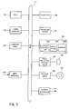
- Fig. 3 is an exterior perspective view showing a state in which the display unit is rotated almost 90 degrees with respect to the main unit.
- the display unit 30 can be rotated via this state so that the display screen 31 is turned to the side opposite to the keyboard 21.
- Fig. 4 is an exterior perspective view showing a state in which the display unit is laid over the main unit so that the display screen is turned upward.
- the display unit 30 is rotated via an attitude shown in Fig. 3 so that the display screen 31 is turned to the side opposite to the keyboard 21, and then the display unit 30 is laid over the main unit 20 with the back of the display screen 31 of the display unit 30 turned toward the main unit 20, which is in a second closed state shown in Fig. 4 .
- the second closed state corresponds to an example of the second usage state according to the present invention.
- an operation mode in which the personal computer 10 is used in the second closed state is referred to as a tablet mode.
- the display screen 31 is a display screen having a pen input function, which is provided with an electromagnetic induction-type digitizer on the back side thereof, and detects the position indicated on the display screen;
- the usually adopted usage mode is one in which the personal computer 10 in the tablet mode is held with one arm, and the display screen is operated by holding a pen (not shown) with the hand of the other arm.
- the display image on the display screen 31 is rotated by 90 degrees compared to the open state shown in Fig. 1 . That is to say, in the tablet mode, information is displayed on the display screen 31 with the direction perpendicular to the rotation axis of the display unit 30 as the vertical direction.
- Fig. 5 is a diagram of the internal configuration of the personal computer 10.
- the personal computer 10 incorporates a CPU 101 that executes various programs, a main memory 102 to which the program stored in a hard disk device 103 is read out to be executed by the CPU 101, the hard disk device 103 in which the various programs and data are stored, a display mechanism 104 that is responsible for processing information display, an operator 106 that includes the keyboard 21 and the track pad 22, a small recording medium drive 108 where a small recording medium 200 is loaded and accessed, a CD/DVD drive 109 where a CD-ROM 210 or a DVD is loaded and accessed, an input interface 105 that inputs data from an external device, an output interface 110 that outputs data to an external device, and the fingerprint sensor 33, which is also shown in Fig.
- the display mechanism 104 is composed of a display controller 1041 that controls the orientation of information displayed on the display screen 31 shown in Fig. 1 , a display device 1042 that displays information on the display screen 31, and a digitizer 1043 that is mounted on the back of the display screen 31.
- the display controller 1041 corresponds to an example of the display control section according to the present invention.
- Fig. 6 is a magnified view of the coupling unit 40.
- Fig. 6 shows the coupling unit 40 in a state in which the display unit 30 is fully opened with respect to the main unit 20.
- the coupling unit 40 includes stoppers 300 that prohibit the rotation of the display unit 30, a rotation section 400 that rotates the display unit 30 in the arrow B direction in Fig. 1 , and opening/closing sections 500 that open/close the display unit 30 in the arrow A direction in Fig. 1 .
- the stopper 300 corresponds to an example of the stopper according to the present invention
- the rotation section 400 corresponds to an example of the rotation axis according to the present invention
- the opening/closing section 500 corresponds to an example of the opening/closing axis according to the present invention.
- Each stopper 300 is energized vertically upward (upward in Fig. 6 ) with respect to the main unit 20, and has an arm 310 extending from the center of the rotation axis of the display unit 30 to one side.
- a protrusion 320 protruding vertically upward (upward in Fig. 6 ) from the end of each arm 310 with respect to the main unit 20 is also provided.
- the arm 310 is made of a metal material, and the protrusion 320 is made of a resin material having a higher lubricating property (more easily deformed) than that of the arm 310.
- the arm 310 corresponds to the arm according to the present invention, and the protrusion 320 corresponds to an example of the stopper-side contact member according to the present invention.
- the rotation section 400 has a rotor 410 which serves as the rotation axis of the display unit 30, and an arm 420 that extends from the rotor 410, and extends from the center of the rotation axis to both sides, and has the opening/closing sections 500, which are attached on each side.
- Each opening/closing section 500 opens/closes the display unit 30 by rotating about the arm 420 of the rotation section 400, and has a fixture 510 that is fixed to the display unit 30, and a front section 520 that is formed on a portion of the fixture 510, and comes into contact with the protrusion 320 on the stopper 300.
- the opening/closing section 500 rotates with the arm 420 extending from the rotor 410 when the rotor 410 of the rotation section 400 is rotated.
- the fixture 510 and the front section 520 provided thereon are made of a metal member as with the arm 420.
- the front section 520 corresponds to an example of the second housing-side contact member according to the present invention.
- the front section 520 has a tapered shape whose peripheral portion coming into contact with the protrusion 320 of the stopper 300 has a predetermined curve to allow the rotation control described later to be achieved.
- Fig. 6 the fixture 510 of the opening/closing section 500 is laid flat, the front section 520 is turned forward, and the display unit 30 is fully opened with respect to the main unit 20.
- the opening/closing section 500 rotates about the arm 420 to close the display unit 30.
- the front section 520 of the opening/closing section 500 moves downward as the display unit 30 is closed, and gradually pushes down the protrusion 320 of the stopper 300.
- Fig. 7 is a magnified view of the coupling unit 40 in a state in which the display unit 30 is standing with respect to the main unit 20.
- the front section 520 of the opening/closing section 500 is turned vertically downward (downward in Fig. 6 ) with respect to the main unit 20, and the protrusion 320 of the stopper 300 is pushed down most (as far as possible).
- Fig. 8 is a magnified view around the coupling unit while the personal computer 10 is being assembled.
- the rotor 410 of the rotation section 400 is housed in the main unit 20
- the arm 310 of the rotation section 400 is housed in the display unit 30
- the fixture 510 of the opening/closing section 500 is fixed to the display unit 30
- the front section 520 of the opening/closing section 500 protrudes from the under surface of the display unit 30
- the arm 310 of the stopper 300 is housed in the main unit 20
- the protrusion 320 of the stopper 300 protrudes from the main unit 20 and faces the front section 520 of the opening/closing section 500.
- Fig. 9 is magnified view around the coupling unit in the personal computer 10 that has been assembled.
- the side of the main unit 20 that is closer to the coupling unit 40 than the keyboard 21 is covered with a cover 28, and the rotor 410 of the rotation section 400 and the arm 310 of the stopper 300 are hidden.
- the coupling unit 40 is constituted as described above.
- Figs. 10 (A) and (B) are diagrams illustrating the method of restricting/releasing the rotation of the display unit 30 in the coupling unit 40.
- Fig. 10 (A) schematically shows the configuration of the coupling unit 40 in a state in which the display unit 30 is fully opened with respect to the main unit 20.
- the rotor 410 of the rotation section 400 has a depressed portion 401, which opens downward, and the arm 310 of the stopper 300 has a protruding portion 301, which protrudes upward, and is fitted into the depressed portion 401 of the rotor 410.
- the depressed portion 401 corresponds to an example of the rotation axis-side fitting section according to the present invention, and also corresponds to an example of the depressed portion according to the present invention.
- the protruding portion 301 corresponds to an example of the stopper-side fitting section, and also corresponds to an example of the protruding portion according to the present invention.
- the opening/closing section 500 When the display unit 30 is widely opened with respect to the main unit 20, the opening/closing section 500 is laid backwards with respect to the body unit 20, and the front section 520 of the opening/closing section 500 is not pushing down the protrusion 320 of the stopper 300. Since the stopper 300 is energized upward by a spring with respect to the main unit 20, in a state shown in Fig. 10 (A) , the protruding portion 301 of the stopper 300 is fitted into (engages with) the depressed portion 401 of the rotation section 400 to prohibit the rotation of the rotation section 400.
- the opening/closing section 500 stands up with respect to the main unit 20, and the front section 520 of the opening/closing section 500 starts pushing down the protrusion 320 of the stopper 300.
- the stopper 300 is pushed down, and the protruding portion 301 of the stopper 300 starts disengaging from the depressed portion 401.
- Fig. 10 (B) schematically shows the configuration of the coupling unit 40 in a state in which the display unit 30 is standing up with respect to the main unit 20.
- the protruding portion 301 of the stopper 300 When the display unit 30 is erected and the opening/closing angle reaches the upper limit of a predetermined specified opening angle (80 to 100 degrees in this example), the protruding portion 301 of the stopper 300 fully disengages from the depressed portion 401, and the prohibition of the rotation of the rotation section 400 by the stopper 300 is released.
- a predetermined specified opening angle 80 to 100 degrees in this example
- the opening/closing section 500 mounted on the arm 420 of the rotation section 400 and fixed to the display unit 30 also rotates with the rotation section 400.
- a set of the protrusion 320 of the stopper 300 and the front section 520 of the opening/closing section 500, which are brought into contact with each other, are provided only on both sides of the center of the rotation axis of the rotation section 400, when the rotation section 400 rotates, the contact of the stopper 300 with the opening/closing section 500 are released, thus allowing smooth rotation to be achieved.
- the opening/closing section 500 is laid forward so as to allow the fixture 510 to face the main unit 20 as compared with Fig. 10 (A) , weakening the force of the front section 520 of the opening/closing section 500 that pushes down the protrusion 320 of the stopper 300.
- the stopper 300 is energized upward by the spring, thus the protruding portion 301 of the stopper 300 is fitted into the depressed portion 401.
- a lock mechanism provided in a conventional personal computer to stop the rotation of the display unit 30 need not be provided near the display screen 31, allowing the design to be improved.
- the electronic apparatus of the present invention may be applied to a personal computer without a tablet function, an electronic notepad, and the like.
Landscapes
- Engineering & Computer Science (AREA)
- Theoretical Computer Science (AREA)
- Computer Hardware Design (AREA)
- Physics & Mathematics (AREA)
- Human Computer Interaction (AREA)
- General Engineering & Computer Science (AREA)
- General Physics & Mathematics (AREA)
- Mathematical Physics (AREA)
- Signal Processing (AREA)
- Casings For Electric Apparatus (AREA)
- Pivots And Pivotal Connections (AREA)
- Telephone Set Structure (AREA)
Abstract
Description
- The present invention relates to an electronic apparatus in which a second housing is openably/closably and rotatably coupled with respect to a first housing.
- In portable electronic apparatuses such as laptop personal computers and mobile phones, a configuration in which an upper housing having a display screen is openably/closably coupled with respect to a lower housing having a keyboard and a push button has been widely used. Such an electronic apparatus is folded so that the upper housing is laid over the lower housing when the apparatus is carried around, and at the time of operation, the upper housing is opened so that the keyboard and push button may be used; thus the portability of the apparatus is increased without downsizing the keyboard and push button.
- Further, in recent years, electronic apparatuses have also been known in which an upper housing is openably/closably and rotatably coupled with respect to a lower housing (see, for example, Japanese Patent Application Publication No.
8-191420 2004-118409 - Incidentally, although in an electronic apparatus in which an upper housing is rotatable with respect to a lower housing, it is usually assumed that the upper housing is rotated with the upper housing standing with respect to the lower housing, practically, a user who is not familiar with the operation of the apparatus sometimes rotates the upper housing with the apparatus closed or with the apparatus widely opened, which may cause the upper housing and the lower housing to rub against each other and get damaged, or may cause the breakage of the display screen. Conventionally, although a hook to fix the upper housing to the lower housing is sometimes provided on the top of the display screen in order to prevent the rotation in a closed state, there are problems that the appearance is deteriorated, and a case where the upper housing is rotated with the upper housing widely opened cannot be addressed.
- The present invention has been made in view of the above circumstances and may provide an electronic apparatus that can prevent damage from occurring when a housing is being rotated.
- An electronic apparatus of the present invention includes:
- a first housing;
- a second housing; and
- a coupling unit that openably/closably and rotatably couples the second housing with the first housing,
- wherein the coupling unit is a biaxial coupling unit having a rotation axis that vertically extends when the first housing is placed on a horizontal table, and is rotatably coupled to the first housing, and an opening/closing axis that is fixed to the rotation axis, horizontally extends, openably/closably supports the second housing with respect to the first housing, and rotates as the rotation axis rotates,
- the coupling unit includes stoppers to permit rotation about the rotation axis only when the second housing is opened with respect to the first housing within a range of rotation-allowing opening angle that allows for rotation.
- In the electronic apparatus of the present invention, although the second housing is openably/closably and rotatably coupled to the first housing, the rotation of the second housing is prohibited by the stoppers when the second housing is opened with respect to the first housing beyond the range of rotation-allowing opening angle that allows for rotation. Therefore, a problem that the second housing is rotated with the second housing closed or widely opened with respect to the first housing, and hits an obstacle, which results in the breakage of the second housing, can be prevented.
- Further, in the electronic apparatus of the present invention, it is preferred that the stoppers are unrotatably supported by the first housing, and each of the stoppers and the rotation axis have a stopper-side fitting section and a rotation axis-side fitting section, respectively, which are fitted into each other (which mutually engage or interlock) in a closed state in which the second housing is laid over the first housing, and
the stopper and a second housing assembly, which includes the second housing and the opening/closing axis, have a stopper-side contact member and a second housing-side contact member, respectively, which are brought into contact with each other to release the fit (mutual engagement) of the stopper-side fitting section into the rotation axis-side fitting section when the second housing is opened within the range of rotation-allowing opening angle from the closed state. - When the second housing is in the closed state in which the second housing is laid over the first housing, the stopper-side fitting section and the rotation axis-side fitting section are fitted into each other to prohibit the rotation of the second housing, and when the second housing is opened within the range of rotation-allowing opening angle from the closed state, the stopper-side contact member and the second housing-side contact member are brought into contact with each other to release the fit of the stopper-side fitting section into the rotation axis-side fitting section, allowing the open/closed state of the second housing and the prohibition/release of the rotation of the second housing to be easily interlocked. Further, although conventionally, a lock mechanism to stop rotation is usually provided near the display screen so that the housing is not rotated when the personal computer is carried around with the personal computer closed, in the electronic apparatus of the present invention, in the closed state, the rotation of the second housing is prohibited, allowing the lock mechanism near the display screen to be eliminated, which presents an excellent design advantage.
- Further, in the electronic apparatus of the present invention, it is preferred that when the second housing is rotated about the rotation axis after the second housing-side contact member is brought into contact with the stopper-side contact member, the contact of the second housing-side contact member with the stopper-side contact member is released, and the release of the fit (from engagement) of the stopper-side fitting section into the rotation axis-side fitting section is kept.
- According to the preferred electronic apparatus, in a state in which the second housing is opened/closed beyond the range of rotation-allowing opening angle, the rotation of the second housing can be prohibited, on the other hand, when the second housing is opened/closed beyond the range of rotation-allowing opening angle after the second housing is rotated, the rotation of the second housing can be allowed.
- Furthermore, in the electronic apparatus of the present invention, it is preferred that the stopper-side fitting section is formed of a protruding portion that protrudes upward, and the rotation axis-side fitting section is formed of a depressed portion that opens downward, and into which the protruding portion is capable of engaging,
the stopper is energized upward by a spring and the protruding portion engages the depressed portion in the closed state, and the second housing-side contact member pushes down the stopper-side contact member from above to remove the protruding portion from the depressed portion when the second housing is opened within the range of rotation-allowing opening angle from the closed state. - In the closed state of the second housing, the protruding portion of the stopper-side fitting section engages the depressed portion of the rotation axis-side fitting section to prohibit the rotation of the second section, and when the second housing is opened within the range of rotation-allowing opening angle from the closed state, the second housing-side contact member provided on the second housing pushes down the stopper-side contact member from above to push down the depressed portion of the stopper-side fitting section, allowing the prohibition/release of the rotation of the second housing to be easily controlled.
- Furthermore, in the electronic apparatus of the present invention, it is preferred that a set (pair) of the stopper-side fitting section and the rotation axis-side fitting section, and a set of the stopper-side contact member and the second housing-side contact member are provided, respectively, on both sides of the center of the rotation axis.
- The set of the stopper-side fitting section and the rotation axis-side fitting section, and the set of the stopper-side contact member and the second housing-side contact member are provided, respectively, on both sides of the center of the rotation axis, thus allowing the prohibition/release of the rotation of the second housing to be reliably controlled, and preventing the interference of the stopper-side contact member with the second housing-side contact member after the start of rotation of the second housing, which results in achievement of smooth rotation.
- Further, in the electronic apparatus of the present invention, it is preferred that the stopper-side contact member is made of a stiffer (harder) material than that of a portion other than the stopper-side fitting section of the stopper.
- The stopper-side contact member is made of the stiffer material, thus allowing abrasion due to contact with the second housing-side contact member to be suppressed.
- Furthermore, in the electronic apparatus of the present invention, it is preferred that the stopper has an arm extending on both sides of the center of the rotation axis, the stopper-side fitting section at an intermediate position of the arm, and the stopper-side contact member at an end of the arm.
- According to the preferred electronic apparatus, the prohibition/release of the rotation of the second housing can be controlled with a simple mechanism.
- Moreover, in the electronic apparatus of the present invention, it is preferred that the second housing-side contact member is a metal member, and the stopper-side contact member is a resin member having a higher lubricating property (softer/more resilient) than that of the second housing-side contact member. Selecting the material of each contact member in this manner allows generation of flakes from the stopper-side contact member due to the rotation of the second housing to be prevented, and allows malfunction of the electronic apparatus due to the penetration of the flakes into the second housing to be prevented.
- Further, in the electronic apparatus of the present invention, it is preferred that the second housing has a display screen where information is displayed.
- Furthermore, in the electronic apparatus of the present invention, it is preferred that the first housing has a keyboard by which instructions corresponding to operation are entered.
- Moreover, in the electronic apparatus of the present invention, it is preferred that the electronic apparatus is provided with display control means that displays, in a first usage state in which the second housing is opened with respect to the first housing, information in a first display mode in which information is displayed on the display screen with the direction of the rotation axis as the vertical direction, and also displays, in a second usage state in which the second housing is laid over the first housing with the display screen turned outward, information in a second display mode in which information is displayed with the direction perpendicular to the rotation axis as the vertical direction.
- A tablet personal computer is convenient when it can be used in such a manner that, in a normal usage state (first usage state) using a keyboard or the like, the display screen is used in landscape orientation with the direction of the rotation axis as the vertical direction, and when the tablet function is used (second usage state), the display screen is used in portrait orientation with the direction perpendicular to the rotation axis as the vertical direction. According to the electronic apparatus of the present invention, information can be displayed in the orientation that is suited to each application in the first usage state and the second usage state.
- According to the present invention, in an electronic apparatus in which two housings are openably/closably and rotatably coupled to each other, damages occurring when the housing is being rotated can be prevented.
- Reference is made, by way of example only, to the accompanying drawings in which:
-
Fig. 1 is an exterior perspective view of a personal computer to which an embodiment of the present invention is applied; -
Fig. 2 is an exterior perspective view showing an electronic apparatus in a state in which a display unit is closed over a main unit; -
Fig. 3 is an exterior perspective view showing a state in which the display unit is rotated almost 90 degrees with respect to the main unit; -
Fig. 4 is an exterior perspective view showing a state in which the display unit is laid over the main unit with the display screen turned upward; -
Fig. 5 is a diagram of the internal configuration of the personal computer; -
Fig. 6 is a magnified view of a coupling unit; -
Fig. 7 is a magnified view of the coupling unit in a state in which the display unit is standing with respect to the main unit; -
Fig. 8 is a magnified view around the coupling unit while the personal computer is being assembled; -
Fig. 9 is magnified view around the coupling unit in the personal computer that has been assembled; and -
Figs. 10 (A) and (B) are diagrams illustrating the method of restricting/releasing the rotation of the display unit in the coupling unit. - An embodiment of the present invention will now be described with reference to the drawings.
-
Fig. 1 is an exterior perspective view of a personal computer to which an embodiment of the present invention is applied. - A
personal computer 10 shown inFig. 1 is provided with an input device that incorporates an electromagnetic induction-type digitizer on the back side of adisplay screen 31, and detects the position on thedisplay screen 31 indicated with a stylus pen so as to allow instruction input. Note that, as the input device, a touch panel which is incorporated into thedisplay screen 31 may be used instead of the digitizer and the stylus pen. - The
personal computer 10 is provided with amain unit 20 and adisplay unit 30, and themain unit 20 and thedisplay unit 30 are coupled by abiaxial coupling unit 40 so that thedisplay unit 30 can be opened/closed in the arrow A-A direction, and can be rotated (about the rotation axis perpendicular to the main unit 20) in the arrow B-B direction, with respect to themain unit 20. Note that in the personal computer of the present embodiment, in a state in which thedisplay unit 30 is opened/closed beyond a predetermined specified opening angle (80 to 100 degrees in the present embodiment) with thecoupling unit 40, the rotation of thedisplay unit 30 about the rotation axis is prohibited by a rotation control mechanism. The rotation control mechanism will be described later. Thepersonal computer 10 is shown inFig. 1 in a state in which thedisplay unit 30 is opened with respect to the main unit 20 (open state), and the open state corresponds to the first usage state according to the present invention. Further, themain unit 20 corresponds to an example of the first housing according to the present invention, thedisplay unit 30 corresponds to an example of the second housing according to the present invention, and thecoupling unit 40 corresponds to an example of the coupling unit according to the present invention. - The
main unit 20 is provided with akeyboard 21, atrack pad 22, aleft click button 23 and aright click button 24, as well as a rubberdisplay unit receiver 34 to reduce abrasion due to collision caused when thedisplay unit 30 is opened/closed and rotated. Furthermore, themain unit 20 is provided with, on its one side, an opening/closing cover 26a for anoptical disk drive 26 where an optical disk such as CDs and DVDs is loaded, driven and accessed, and aneject button 26b, which is pushed to open the opening/closing cover 26a, is provided on the opening/closing cover 26a. Thekeyboard 21 corresponds to an example of the keyboard according to the present invention. - The
display unit 30 of thepersonal computer 10 has thedisplay screen 31 spreading over the front surface thereof. Further, thedisplay unit 30 haspush buttons 32 on its right edge under thedisplay screen 31, and afingerprint sensor 33, which recognizes a fingerprint when a person moves his/her finger along the sensor, on its left edge. Thedisplay screen 31 corresponds to an example of the display screen according to the present invention. In the open state shown inFig. 1 , information is displayed on thedisplay screen 31 with the direction of the rotation axis of thedisplay unit 30 as the vertical direction. -
Fig. 2 is an exterior perspective view showing the electronic apparatus in a state in which thedisplay unit 30 is closed over themain unit 20. - In
Fig. 2 , thedisplay unit 30 is laid over themain unit 20 with the display screen 31 (seeFig. 1 ) turned toward themain unit 20. Hereinafter, this state is referred to as a first closed state. - In an open state shown in
Fig. 1 , when thedisplay unit 30 is closed in the arrow A direction, as shown inFig. 2 , thedisplay screen 31 is hidden inward, and the back of thedisplay screen 31 is exposed outward, which is in the first closed state. Thepersonal computer 10 can be carried around in the first closed state, which prevents damage and dirt from affecting thedisplay screen 31. -
Fig. 3 is an exterior perspective view showing a state in which the display unit is rotated almost 90 degrees with respect to the main unit. - The
display unit 30 can be rotated via this state so that thedisplay screen 31 is turned to the side opposite to thekeyboard 21. -
Fig. 4 is an exterior perspective view showing a state in which the display unit is laid over the main unit so that the display screen is turned upward. - The
display unit 30 is rotated via an attitude shown inFig. 3 so that thedisplay screen 31 is turned to the side opposite to thekeyboard 21, and then thedisplay unit 30 is laid over themain unit 20 with the back of thedisplay screen 31 of thedisplay unit 30 turned toward themain unit 20, which is in a second closed state shown inFig. 4 . The second closed state corresponds to an example of the second usage state according to the present invention. Hereinafter, an operation mode in which thepersonal computer 10 is used in the second closed state is referred to as a tablet mode. - As described above, the
display screen 31 is a display screen having a pen input function, which is provided with an electromagnetic induction-type digitizer on the back side thereof, and detects the position indicated on the display screen; the usually adopted usage mode is one in which thepersonal computer 10 in the tablet mode is held with one arm, and the display screen is operated by holding a pen (not shown) with the hand of the other arm. Considering the relationship with the line of sight when thepersonal computer 10 in the tablet mode is held with an arm, the display image on thedisplay screen 31 is rotated by 90 degrees compared to the open state shown inFig. 1 . That is to say, in the tablet mode, information is displayed on thedisplay screen 31 with the direction perpendicular to the rotation axis of thedisplay unit 30 as the vertical direction. - Now, the internal configuration of the
personal computer 10 will be described. -
Fig. 5 is a diagram of the internal configuration of thepersonal computer 10. - As shown in
Fig. 5 , thepersonal computer 10 incorporates aCPU 101 that executes various programs, amain memory 102 to which the program stored in ahard disk device 103 is read out to be executed by theCPU 101, thehard disk device 103 in which the various programs and data are stored, adisplay mechanism 104 that is responsible for processing information display, anoperator 106 that includes thekeyboard 21 and thetrack pad 22, a smallrecording medium drive 108 where asmall recording medium 200 is loaded and accessed, a CD/DVD drive 109 where a CD-ROM 210 or a DVD is loaded and accessed, aninput interface 105 that inputs data from an external device, anoutput interface 110 that outputs data to an external device, and thefingerprint sensor 33, which is also shown inFig. 1 , and each component is connected to one another through abus 111. Note that thedisplay mechanism 104 is composed of adisplay controller 1041 that controls the orientation of information displayed on thedisplay screen 31 shown inFig. 1 , adisplay device 1042 that displays information on thedisplay screen 31, and adigitizer 1043 that is mounted on the back of thedisplay screen 31. Thedisplay controller 1041 corresponds to an example of the display control section according to the present invention. - Now, the
coupling unit 40 will be described in detail. -
Fig. 6 is a magnified view of thecoupling unit 40. -
Fig. 6 shows thecoupling unit 40 in a state in which thedisplay unit 30 is fully opened with respect to themain unit 20. Thecoupling unit 40 includesstoppers 300 that prohibit the rotation of thedisplay unit 30, arotation section 400 that rotates thedisplay unit 30 in the arrow B direction inFig. 1 , and opening/closing sections 500 that open/close thedisplay unit 30 in the arrow A direction inFig. 1 . Thestopper 300 corresponds to an example of the stopper according to the present invention, therotation section 400 corresponds to an example of the rotation axis according to the present invention, and the opening/closing section 500 corresponds to an example of the opening/closing axis according to the present invention. - Each
stopper 300 is energized vertically upward (upward inFig. 6 ) with respect to themain unit 20, and has anarm 310 extending from the center of the rotation axis of thedisplay unit 30 to one side. Aprotrusion 320 protruding vertically upward (upward inFig. 6 ) from the end of eacharm 310 with respect to themain unit 20 is also provided. Thearm 310 is made of a metal material, and theprotrusion 320 is made of a resin material having a higher lubricating property (more easily deformed) than that of thearm 310. Thearm 310 corresponds to the arm according to the present invention, and theprotrusion 320 corresponds to an example of the stopper-side contact member according to the present invention. - The
rotation section 400 has arotor 410 which serves as the rotation axis of thedisplay unit 30, and anarm 420 that extends from therotor 410, and extends from the center of the rotation axis to both sides, and has the opening/closing sections 500, which are attached on each side. - Each opening/
closing section 500 opens/closes thedisplay unit 30 by rotating about thearm 420 of therotation section 400, and has afixture 510 that is fixed to thedisplay unit 30, and afront section 520 that is formed on a portion of thefixture 510, and comes into contact with theprotrusion 320 on thestopper 300. The opening/closing section 500 rotates with thearm 420 extending from therotor 410 when therotor 410 of therotation section 400 is rotated. Thefixture 510 and thefront section 520 provided thereon are made of a metal member as with thearm 420. Thefront section 520 corresponds to an example of the second housing-side contact member according to the present invention. Thefront section 520 has a tapered shape whose peripheral portion coming into contact with theprotrusion 320 of thestopper 300 has a predetermined curve to allow the rotation control described later to be achieved. - In
Fig. 6 , thefixture 510 of the opening/closing section 500 is laid flat, thefront section 520 is turned forward, and thedisplay unit 30 is fully opened with respect to themain unit 20. When thedisplay unit 30 is erected, the opening/closing section 500 rotates about thearm 420 to close thedisplay unit 30. At that time, thefront section 520 of the opening/closing section 500 moves downward as thedisplay unit 30 is closed, and gradually pushes down theprotrusion 320 of thestopper 300. -
Fig. 7 is a magnified view of thecoupling unit 40 in a state in which thedisplay unit 30 is standing with respect to themain unit 20. - When the
display unit 30 is standing with respect to themain unit 20, thefront section 520 of the opening/closing section 500 is turned vertically downward (downward inFig. 6 ) with respect to themain unit 20, and theprotrusion 320 of thestopper 300 is pushed down most (as far as possible). -
Fig. 8 is a magnified view around the coupling unit while thepersonal computer 10 is being assembled. - As shown in
Fig. 8 , therotor 410 of therotation section 400 is housed in themain unit 20, thearm 310 of therotation section 400 is housed in thedisplay unit 30, thefixture 510 of the opening/closing section 500 is fixed to thedisplay unit 30, thefront section 520 of the opening/closing section 500 protrudes from the under surface of thedisplay unit 30, thearm 310 of thestopper 300 is housed in themain unit 20, theprotrusion 320 of thestopper 300 protrudes from themain unit 20 and faces thefront section 520 of the opening/closing section 500. -
Fig. 9 is magnified view around the coupling unit in thepersonal computer 10 that has been assembled. - As shown in
Fig. 9 , the side of themain unit 20 that is closer to thecoupling unit 40 than thekeyboard 21 is covered with acover 28, and therotor 410 of therotation section 400 and thearm 310 of thestopper 300 are hidden. - Basically, the
coupling unit 40 is constituted as described above. - Then, the method of restricting/releasing the rotation of the
display unit 30 in thecoupling unit 40 will be described in detail. -
Figs. 10 (A) and (B) are diagrams illustrating the method of restricting/releasing the rotation of thedisplay unit 30 in thecoupling unit 40. -
Fig. 10 (A) schematically shows the configuration of thecoupling unit 40 in a state in which thedisplay unit 30 is fully opened with respect to themain unit 20. - The
rotor 410 of therotation section 400 has adepressed portion 401, which opens downward, and thearm 310 of thestopper 300 has a protrudingportion 301, which protrudes upward, and is fitted into thedepressed portion 401 of therotor 410. Thedepressed portion 401 corresponds to an example of the rotation axis-side fitting section according to the present invention, and also corresponds to an example of the depressed portion according to the present invention. Further, the protrudingportion 301 corresponds to an example of the stopper-side fitting section, and also corresponds to an example of the protruding portion according to the present invention. - When the
display unit 30 is widely opened with respect to themain unit 20, the opening/closing section 500 is laid backwards with respect to thebody unit 20, and thefront section 520 of the opening/closing section 500 is not pushing down theprotrusion 320 of thestopper 300. Since thestopper 300 is energized upward by a spring with respect to themain unit 20, in a state shown inFig. 10 (A) , the protrudingportion 301 of thestopper 300 is fitted into (engages with) thedepressed portion 401 of therotation section 400 to prohibit the rotation of therotation section 400. - When the
display unit 30 is gradually erected from the state shown inFig. 10 (A) , the opening/closing section 500 stands up with respect to themain unit 20, and thefront section 520 of the opening/closing section 500 starts pushing down theprotrusion 320 of thestopper 300. As a result, thestopper 300 is pushed down, and the protrudingportion 301 of thestopper 300 starts disengaging from thedepressed portion 401. -
Fig. 10 (B) schematically shows the configuration of thecoupling unit 40 in a state in which thedisplay unit 30 is standing up with respect to themain unit 20. - When the
display unit 30 is erected and the opening/closing angle reaches the upper limit of a predetermined specified opening angle (80 to 100 degrees in this example), the protrudingportion 301 of thestopper 300 fully disengages from thedepressed portion 401, and the prohibition of the rotation of therotation section 400 by thestopper 300 is released. In the standing state shown inFig. 10 (B) , thefront section 520 of the opening/closing section 500 is erected with respect to themain unit 20, thus thestopper 300 is pushed down most. - When the
display unit 30 is rotated in a state in which the prohibition of the rotation by thestopper 300 is released, the opening/closing section 500 mounted on thearm 420 of therotation section 400 and fixed to thedisplay unit 30 also rotates with therotation section 400. At that time, since a set of theprotrusion 320 of thestopper 300 and thefront section 520 of the opening/closing section 500, which are brought into contact with each other, are provided only on both sides of the center of the rotation axis of therotation section 400, when therotation section 400 rotates, the contact of thestopper 300 with the opening/closing section 500 are released, thus allowing smooth rotation to be achieved. - When the display unit is further closed from the state shown in
Fig. 10 (B) , the opening/closing section 500 is laid forward so as to allow thefixture 510 to face themain unit 20 as compared withFig. 10 (A) , weakening the force of thefront section 520 of the opening/closing section 500 that pushes down theprotrusion 320 of thestopper 300. When thedisplay unit 30 is closed, and the opening/closing angle reaches the lower limit of the predetermined specified opening angle (80 to 100 degrees in this example), thestopper 300 is energized upward by the spring, thus the protrudingportion 301 of thestopper 300 is fitted into thedepressed portion 401. - In this manner, according to the present embodiment, since the rotation is allowed only when the
display unit 30 is at the predetermined specified opening angle (80 to 100 degrees in this example) with respect to themain unit 20, a problem that thedisplay screen 31 is broken because thedisplay unit 30 is rotated when thedisplay unit 30 is closed or widely opened can be prevented. - In addition, as shown in
Fig. 10 (B) , since the rotation is prohibited when thedisplay unit 30 is closed with respect to themain unit 20, a lock mechanism provided in a conventional personal computer to stop the rotation of thedisplay unit 30 need not be provided near thedisplay screen 31, allowing the design to be improved. - Although an example in which the electronic apparatus of the present invention is applied to a tablet personal computer has been described herein, the electronic apparatus of the present invention may be applied to a personal computer without a tablet function, an electronic notepad, and the like.
Claims (11)
- An electronic apparatus, comprising:a first housing;a second housing; anda coupling unit that openably/closably and rotatably couples the second housing with the first housing,wherein the coupling unit is a biaxial coupling unit comprised of a rotation axis that vertically extends when the first housing is placed on a horizontal table, and is rotatably coupled to the first housing, and an opening/closing axis that is fixed to the rotation axis, horizontally extends, openably/closably supports the second housing with respect to the first housing, and rotates as the rotation axis rotates, andthe coupling unit comprises a stopper to rotate the rotation axis only when the second housing is opened with respect to the first housing within a range of rotation-allowing opening angle that allows for rotation.
- The electronic apparatus according to claim 1, wherein the stopper is unrotatably supported by the first housing, and the stopper and the rotation axis comprise a stopper-side fitting section and a rotation axis-side fitting section, respectively, which are fitted into each other in a closed state in which the second housing is laid over the first housing, and
the stopper and a second housing assembly, which includes the second housing and the opening/closing axis, comprise a stopper-side contact member and a second housing-side contact member, respectively, which are brought into contact with each other to release the fit of the stopper-side fitting section into the rotation axis-side fitting section when the second housing is opened within the range of rotation-allowing opening angle from the closed state. - The electronic apparatus according to claim 2, wherein when the second housing is rotated about the rotation axis after the second housing-side contact member is brought into contact with the stopper-side contact member, the contact of the second housing-side contact member with the stopper-side contact member is released, and the release of the fit of the stopper-side fitting section into the rotation axis-side fitting section is kept.
- The electronic apparatus according to claim 2 or 3, wherein the stopper-side fitting section is formed of a protruding portion that protrudes upward, and the rotation axis-side fitting section is formed of a depressed portion that opens downward, and into which the protruding portion is fitted, and
the stopper is energized upward by a spring and the protruding portion is fitted into the depressed portion in the closed state, and the second housing-side contact member pushes down the stopper-side contact member from above to remove the protruding portion from the depressed portion when the second housing is opened within the range of rotation-allowing opening angle from the closed state. - The electronic apparatus according to claim 2, 3 or 4, wherein a set of the stopper-side fitting section and the rotation axis-side fitting section, and a set of the stopper-side contact member and the second housing-side contact member are provided, respectively, on both sides of the center of the rotation axis.
- The electronic apparatus according to claim 2, 3, 4, or 5 wherein the stopper-side contact member is made of a stiffer material than that of a portion other than the stopper-side fitting section of the stopper.
- The electronic apparatus according to claim 4, wherein the stopper comprises an arm extending on both sides of the center of the rotation axis, the stopper-side fitting section at a position halfway of the arm, and the stopper-side contact member at an end of the arm.
- The electronic apparatus according to any of claims 2 to 7, wherein the second housing-side contact member is a metal member, and the stopper-side contact member is a resin member having a higher lubricating property than that of the second housing-side contact member.
- The electronic apparatus according to any preceding claim, wherein the second housing comprises a display screen where information is displayed.
- The electronic apparatus according to any preceding claim, wherein the first housing comprises a keyboard by which instructions corresponding to operation is entered.
- The electronic apparatus according to claim 9, further comprising display control means that displays, in a first usage state in which the second housing is opened with respect to the first housing, information in a first display mode in which information is displayed on the display screen with the direction of the rotation axis as the vertical direction, and also displays, in a second usage state in which the second housing is laid over the first housing with the display screen turned outward, information in a second display mode in which information is displayed with the direction perpendicular to the rotation axis as the vertical direction.
Applications Claiming Priority (1)
| Application Number | Priority Date | Filing Date | Title |
|---|---|---|---|
| JP2007173354A JP4912969B2 (en) | 2007-06-29 | 2007-06-29 | Electronics |
Publications (3)
| Publication Number | Publication Date |
|---|---|
| EP2017690A2 true EP2017690A2 (en) | 2009-01-21 |
| EP2017690A3 EP2017690A3 (en) | 2011-04-06 |
| EP2017690B1 EP2017690B1 (en) | 2012-07-25 |
Family
ID=39730606
Family Applications (1)
| Application Number | Title | Priority Date | Filing Date |
|---|---|---|---|
| EP08104527A Ceased EP2017690B1 (en) | 2007-06-29 | 2008-06-24 | Biaxial coupling unit for electronic apparatus |
Country Status (5)
| Country | Link |
|---|---|
| US (1) | US7706137B2 (en) |
| EP (1) | EP2017690B1 (en) |
| JP (1) | JP4912969B2 (en) |
| KR (1) | KR100974010B1 (en) |
| CN (1) | CN101334684B (en) |
Families Citing this family (30)
| Publication number | Priority date | Publication date | Assignee | Title |
|---|---|---|---|---|
| KR100800713B1 (en) * | 2007-01-29 | 2008-02-01 | 삼성전자주식회사 | Handheld terminal |
| US7954203B2 (en) * | 2008-12-19 | 2011-06-07 | Shin Zu Shing Co., Ltd. | Hinge and an electronic device with the hinge |
| US7971321B2 (en) * | 2008-12-19 | 2011-07-05 | Shin Zu Shing Co., Ltd. | Hinge and an electronic device with the hinge |
| US8011065B2 (en) * | 2008-12-24 | 2011-09-06 | Shin Zu Shing Co., Ltd. | Hinge and an electronic device with the hinge |
| JP2011091560A (en) * | 2009-10-21 | 2011-05-06 | Panasonic Corp | Display device holding apparatus, and portable terminal provided with same |
| TWI378204B (en) * | 2009-11-11 | 2012-12-01 | Acer Inc | Rotation angle limitation device and portable electronic device having the same |
| US8795762B2 (en) | 2010-03-26 | 2014-08-05 | Battelle Memorial Institute | System and method for enhanced electrostatic deposition and surface coatings |
| WO2011156275A2 (en) * | 2010-06-07 | 2011-12-15 | Targus Group International, Inc. | Portable electronic device case accessories and related systems and methods |
| CN102374227A (en) * | 2010-08-26 | 2012-03-14 | 鸿富锦精密工业(深圳)有限公司 | Rotation apparatus |
| JP5039216B2 (en) | 2011-02-24 | 2012-10-03 | 株式会社東芝 | Electronics |
| CN102840220A (en) * | 2011-06-21 | 2012-12-26 | 鸿富锦精密工业(深圳)有限公司 | hinge structure |
| US8861187B2 (en) * | 2011-12-19 | 2014-10-14 | Lenovo (Singapore) Pte. Ltd. | Convertible tablet |
| CN103188901A (en) * | 2011-12-29 | 2013-07-03 | 鸿富锦精密工业(武汉)有限公司 | Electronic device |
| WO2013145866A1 (en) * | 2012-03-30 | 2013-10-03 | 日立アロカメディカル株式会社 | Portable ultrasonic diagnostic device |
| JP2014045458A (en) * | 2012-08-28 | 2014-03-13 | Fujitsu Ltd | Fitting base and electronic apparatus |
| US9678535B2 (en) | 2013-01-29 | 2017-06-13 | Hewlett-Packard Development Company, L.P. | Moveable keyboard lattice for a portable electronic device |
| US9223351B2 (en) * | 2013-03-12 | 2015-12-29 | Google Inc. | Moveable display portion of a computing device |
| JP2013168977A (en) * | 2013-04-01 | 2013-08-29 | Funai Electric Co Ltd | Portable terminal |
| TWI535365B (en) * | 2013-11-13 | 2016-05-21 | 仁寶電腦工業股份有限公司 | Electronic device and locking structure thereof |
| US9696754B2 (en) * | 2014-03-26 | 2017-07-04 | Intel Corporation | Hinge having multiple degrees of freedom |
| CN104881081B (en) * | 2014-06-12 | 2018-01-16 | 昆山万禾精密电子有限公司 | Extended base and its intake type pin-jointed structure |
| JP5956521B2 (en) * | 2014-07-31 | 2016-07-27 | レノボ・シンガポール・プライベート・リミテッド | Electronics |
| CN105545928B (en) * | 2014-11-03 | 2019-01-15 | 联想(北京)有限公司 | Rotating device for electronic product and the electronic product with the rotating device |
| US20170060008A1 (en) * | 2015-08-27 | 2017-03-02 | Canon Kabushiki Kaisha | Image forming method, process cartridge and electrophotographic apparatus |
| TWI701987B (en) * | 2018-10-23 | 2020-08-11 | 仁寶電腦工業股份有限公司 | Electronic device |
| CN112445294B (en) * | 2019-08-27 | 2024-05-24 | 纬联电子科技(中山)有限公司 | Fixing assembly, shell assembly and electronic device |
| US12396112B2 (en) * | 2021-12-31 | 2025-08-19 | Lg Display Co., Ltd. | Foldable display apparatus |
| CN114708785B (en) * | 2022-04-08 | 2023-07-21 | 中交二公局第三工程有限公司 | Building modeling display device based on BIM |
| CN116085385B (en) * | 2023-04-10 | 2023-07-18 | 合肥联宝信息技术有限公司 | Rotating shaft assembly and electronic equipment |
| CN221237577U (en) * | 2023-09-14 | 2024-06-28 | 深圳丰汇汽车电子有限公司 | An extended screen |
Citations (2)
| Publication number | Priority date | Publication date | Assignee | Title |
|---|---|---|---|---|
| JPH08191420A (en) | 1995-01-09 | 1996-07-23 | Matsushita Electric Ind Co Ltd | Display holding structure |
| JP2004118409A (en) | 2002-09-25 | 2004-04-15 | Sharp Corp | Information processing device having hinge lock mechanism |
Family Cites Families (10)
| Publication number | Priority date | Publication date | Assignee | Title |
|---|---|---|---|---|
| JPH0395495U (en) * | 1990-01-19 | 1991-09-30 | ||
| JP2000214956A (en) * | 1999-01-25 | 2000-08-04 | Toshiba Corp | Expansion unit |
| JP2004053927A (en) * | 2002-07-19 | 2004-02-19 | Toshiba Corp | Electronics |
| JP2004162888A (en) * | 2002-09-26 | 2004-06-10 | Sharp Corp | Electronic equipment |
| US6804861B2 (en) * | 2002-12-04 | 2004-10-19 | Lite-On Technology Corp. | Rotation shaft mechanism of display portion of portable computer |
| JP4093038B2 (en) * | 2002-12-06 | 2008-05-28 | 日本電気株式会社 | Folding portable device and hinge mechanism thereof |
| JP4238571B2 (en) | 2002-12-06 | 2009-03-18 | 日本電気株式会社 | Foldable portable device, its wiring device and wiring method |
| US7308733B2 (en) * | 2003-05-15 | 2007-12-18 | Lg Electronics Inc. | Swivel hinge assembly and electronic device having the same |
| JP4414281B2 (en) | 2004-05-31 | 2010-02-10 | 京セラ株式会社 | Mobile terminal device |
| JP2006070927A (en) * | 2004-08-31 | 2006-03-16 | Yano Seisakusho:Kk | Hinge mechanism |
-
2007
- 2007-06-29 JP JP2007173354A patent/JP4912969B2/en not_active Expired - Fee Related
-
2008
- 2008-06-23 KR KR1020080059140A patent/KR100974010B1/en not_active Expired - Fee Related
- 2008-06-24 EP EP08104527A patent/EP2017690B1/en not_active Ceased
- 2008-06-27 US US12/215,399 patent/US7706137B2/en not_active Expired - Fee Related
- 2008-06-27 CN CN2008101319057A patent/CN101334684B/en not_active Expired - Fee Related
Patent Citations (2)
| Publication number | Priority date | Publication date | Assignee | Title |
|---|---|---|---|---|
| JPH08191420A (en) | 1995-01-09 | 1996-07-23 | Matsushita Electric Ind Co Ltd | Display holding structure |
| JP2004118409A (en) | 2002-09-25 | 2004-04-15 | Sharp Corp | Information processing device having hinge lock mechanism |
Also Published As
| Publication number | Publication date |
|---|---|
| CN101334684A (en) | 2008-12-31 |
| EP2017690A3 (en) | 2011-04-06 |
| JP4912969B2 (en) | 2012-04-11 |
| KR100974010B1 (en) | 2010-08-05 |
| EP2017690B1 (en) | 2012-07-25 |
| US7706137B2 (en) | 2010-04-27 |
| CN101334684B (en) | 2011-06-15 |
| US20090002927A1 (en) | 2009-01-01 |
| KR20090004538A (en) | 2009-01-12 |
| JP2009015386A (en) | 2009-01-22 |
Similar Documents
| Publication | Publication Date | Title |
|---|---|---|
| EP2017690B1 (en) | Biaxial coupling unit for electronic apparatus | |
| KR100924038B1 (en) | Keyboard removal device for portable hybrid computer | |
| CN102573366B (en) | Electronic device | |
| US6125040A (en) | Information processing apparatus and hook mechanism applicable to the apparatus | |
| EP2662746B1 (en) | Pouch and portable electronic device received therein | |
| EP2733568B1 (en) | Information apparatus and link mechanism of information apparatus | |
| US9846458B2 (en) | Electronic device with damage prevention features | |
| US7859833B2 (en) | Function expansion device and electronic device system | |
| CN1784644A (en) | Sliding screen emerging keyboard | |
| CN103970207A (en) | Tilt mechanism for information device | |
| KR20000029031A (en) | Handheld computer keyboard system | |
| EP2017689A2 (en) | Display device and electronic apparatus | |
| JP4474568B2 (en) | Electronic device and rotatable display lock device | |
| CN102340939B (en) | Flip cover type electronic device structure | |
| KR101227535B1 (en) | Portable electronic device case | |
| JP2001125668A (en) | Hinge mechanism of notebook type personal computer | |
| CN102118934B (en) | Electronic device | |
| US6222724B1 (en) | LCD housing having vertically offset hinges | |
| JP4237095B2 (en) | Information processing device | |
| JP5566273B2 (en) | Portable electronic devices | |
| JP5730598B2 (en) | Portable electronic devices | |
| JP2000222118A (en) | Trackball and information processing apparatus using the same | |
| JP2012156845A (en) | Portable electronic device | |
| KR20040041463A (en) | Keyboard system | |
| KR20040041464A (en) | Keyboard system |
Legal Events
| Date | Code | Title | Description |
|---|---|---|---|
| PUAI | Public reference made under article 153(3) epc to a published international application that has entered the european phase |
Free format text: ORIGINAL CODE: 0009012 |
|
| AK | Designated contracting states |
Kind code of ref document: A2 Designated state(s): AT BE BG CH CY CZ DE DK EE ES FI FR GB GR HR HU IE IS IT LI LT LU LV MC MT NL NO PL PT RO SE SI SK TR |
|
| AX | Request for extension of the european patent |
Extension state: AL BA MK RS |
|
| RTI1 | Title (correction) |
Free format text: BIAXIAL COUPLING UNIT FOR ELECTRONIC APPARATUS |
|
| PUAL | Search report despatched |
Free format text: ORIGINAL CODE: 0009013 |
|
| AK | Designated contracting states |
Kind code of ref document: A3 Designated state(s): AT BE BG CH CY CZ DE DK EE ES FI FR GB GR HR HU IE IS IT LI LT LU LV MC MT NL NO PL PT RO SE SI SK TR |
|
| AX | Request for extension of the european patent |
Extension state: AL BA MK RS |
|
| 17P | Request for examination filed |
Effective date: 20111004 |
|
| AKX | Designation fees paid |
Designated state(s): DE FR GB |
|
| GRAP | Despatch of communication of intention to grant a patent |
Free format text: ORIGINAL CODE: EPIDOSNIGR1 |
|
| GRAS | Grant fee paid |
Free format text: ORIGINAL CODE: EPIDOSNIGR3 |
|
| GRAA | (expected) grant |
Free format text: ORIGINAL CODE: 0009210 |
|
| AK | Designated contracting states |
Kind code of ref document: B1 Designated state(s): DE FR GB |
|
| REG | Reference to a national code |
Ref country code: GB Ref legal event code: FG4D |
|
| REG | Reference to a national code |
Ref country code: DE Ref legal event code: R096 Ref document number: 602008017359 Country of ref document: DE Effective date: 20120920 |
|
| REG | Reference to a national code |
Ref country code: DE Ref legal event code: R082 Ref document number: 602008017359 Country of ref document: DE Representative=s name: HOFFMANN - EITLE, DE Ref country code: DE Ref legal event code: R082 Ref document number: 602008017359 Country of ref document: DE Representative=s name: HOFFMANN - EITLE PATENT- UND RECHTSANWAELTE PA, DE |
|
| PLBE | No opposition filed within time limit |
Free format text: ORIGINAL CODE: 0009261 |
|
| STAA | Information on the status of an ep patent application or granted ep patent |
Free format text: STATUS: NO OPPOSITION FILED WITHIN TIME LIMIT |
|
| 26N | No opposition filed |
Effective date: 20130426 |
|
| REG | Reference to a national code |
Ref country code: DE Ref legal event code: R097 Ref document number: 602008017359 Country of ref document: DE Effective date: 20130426 |
|
| REG | Reference to a national code |
Ref country code: FR Ref legal event code: PLFP Year of fee payment: 9 |
|
| REG | Reference to a national code |
Ref country code: FR Ref legal event code: PLFP Year of fee payment: 10 |
|
| REG | Reference to a national code |
Ref country code: FR Ref legal event code: PLFP Year of fee payment: 11 |
|
| REG | Reference to a national code |
Ref country code: DE Ref legal event code: R081 Ref document number: 602008017359 Country of ref document: DE Owner name: FUJITSU CLIENT COMPUTING LIMITED, KAWASAKI-SHI, JP Free format text: FORMER OWNER: FUJITSU LIMITED, KAWASAKI-SHI, KANAGAWA, JP Ref country code: DE Ref legal event code: R082 Ref document number: 602008017359 Country of ref document: DE Representative=s name: HOFFMANN - EITLE PATENT- UND RECHTSANWAELTE PA, DE |
|
| REG | Reference to a national code |
Ref country code: GB Ref legal event code: 732E Free format text: REGISTERED BETWEEN 20190207 AND 20190213 |
|
| PGFP | Annual fee paid to national office [announced via postgrant information from national office to epo] |
Ref country code: FR Payment date: 20190510 Year of fee payment: 12 |
|
| PGFP | Annual fee paid to national office [announced via postgrant information from national office to epo] |
Ref country code: GB Payment date: 20190619 Year of fee payment: 12 |
|
| PGFP | Annual fee paid to national office [announced via postgrant information from national office to epo] |
Ref country code: DE Payment date: 20200609 Year of fee payment: 13 |
|
| GBPC | Gb: european patent ceased through non-payment of renewal fee |
Effective date: 20200624 |
|
| PG25 | Lapsed in a contracting state [announced via postgrant information from national office to epo] |
Ref country code: GB Free format text: LAPSE BECAUSE OF NON-PAYMENT OF DUE FEES Effective date: 20200624 Ref country code: FR Free format text: LAPSE BECAUSE OF NON-PAYMENT OF DUE FEES Effective date: 20200630 |
|
| REG | Reference to a national code |
Ref country code: DE Ref legal event code: R119 Ref document number: 602008017359 Country of ref document: DE |
|
| PG25 | Lapsed in a contracting state [announced via postgrant information from national office to epo] |
Ref country code: DE Free format text: LAPSE BECAUSE OF NON-PAYMENT OF DUE FEES Effective date: 20220101 |