EP2017564B1 - Arme portable modulaire - Google Patents
Arme portable modulaire Download PDFInfo
- Publication number
- EP2017564B1 EP2017564B1 EP08012288.0A EP08012288A EP2017564B1 EP 2017564 B1 EP2017564 B1 EP 2017564B1 EP 08012288 A EP08012288 A EP 08012288A EP 2017564 B1 EP2017564 B1 EP 2017564B1
- Authority
- EP
- European Patent Office
- Prior art keywords
- module
- lock
- weapon
- magazine
- modular portable
- Prior art date
- Legal status (The legal status is an assumption and is not a legal conclusion. Google has not performed a legal analysis and makes no representation as to the accuracy of the status listed.)
- Active
Links
Images


Classifications
-
- F—MECHANICAL ENGINEERING; LIGHTING; HEATING; WEAPONS; BLASTING
- F41—WEAPONS
- F41A—FUNCTIONAL FEATURES OR DETAILS COMMON TO BOTH SMALLARMS AND ORDNANCE, e.g. CANNONS; MOUNTINGS FOR SMALLARMS OR ORDNANCE
- F41A3/00—Breech mechanisms, e.g. locks
- F41A3/64—Mounting of breech-blocks; Accessories for breech-blocks or breech-block mountings
- F41A3/66—Breech housings or frames; Receivers
-
- F—MECHANICAL ENGINEERING; LIGHTING; HEATING; WEAPONS; BLASTING
- F41—WEAPONS
- F41A—FUNCTIONAL FEATURES OR DETAILS COMMON TO BOTH SMALLARMS AND ORDNANCE, e.g. CANNONS; MOUNTINGS FOR SMALLARMS OR ORDNANCE
- F41A11/00—Assembly or disassembly features; Modular concepts; Articulated or collapsible guns
- F41A11/02—Modular concepts, e.g. weapon-family concepts
-
- F—MECHANICAL ENGINEERING; LIGHTING; HEATING; WEAPONS; BLASTING
- F41—WEAPONS
- F41A—FUNCTIONAL FEATURES OR DETAILS COMMON TO BOTH SMALLARMS AND ORDNANCE, e.g. CANNONS; MOUNTINGS FOR SMALLARMS OR ORDNANCE
- F41A15/00—Cartridge extractors, i.e. devices for pulling cartridges or cartridge cases at least partially out of the cartridge chamber; Cartridge ejectors, i.e. devices for throwing the extracted cartridges or cartridge cases free of the gun
- F41A15/12—Cartridge extractors, i.e. devices for pulling cartridges or cartridge cases at least partially out of the cartridge chamber; Cartridge ejectors, i.e. devices for throwing the extracted cartridges or cartridge cases free of the gun for bolt-action guns
-
- F—MECHANICAL ENGINEERING; LIGHTING; HEATING; WEAPONS; BLASTING
- F41—WEAPONS
- F41A—FUNCTIONAL FEATURES OR DETAILS COMMON TO BOTH SMALLARMS AND ORDNANCE, e.g. CANNONS; MOUNTINGS FOR SMALLARMS OR ORDNANCE
- F41A21/00—Barrels; Gun tubes; Muzzle attachments; Barrel mounting means
- F41A21/48—Barrel mounting means, e.g. releasable mountings for replaceable barrels
-
- F—MECHANICAL ENGINEERING; LIGHTING; HEATING; WEAPONS; BLASTING
- F41—WEAPONS
- F41A—FUNCTIONAL FEATURES OR DETAILS COMMON TO BOTH SMALLARMS AND ORDNANCE, e.g. CANNONS; MOUNTINGS FOR SMALLARMS OR ORDNANCE
- F41A25/00—Gun mountings permitting recoil or return to battery, e.g. gun cradles; Barrel buffers or brakes
- F41A25/10—Spring-operated systems
- F41A25/12—Spring-operated systems using coil springs
-
- F—MECHANICAL ENGINEERING; LIGHTING; HEATING; WEAPONS; BLASTING
- F41—WEAPONS
- F41A—FUNCTIONAL FEATURES OR DETAILS COMMON TO BOTH SMALLARMS AND ORDNANCE, e.g. CANNONS; MOUNTINGS FOR SMALLARMS OR ORDNANCE
- F41A3/00—Breech mechanisms, e.g. locks
- F41A3/12—Bolt action, i.e. the main breech opening movement being parallel to the barrel axis
- F41A3/14—Rigid bolt locks, i.e. having locking elements rigidly mounted on the bolt or bolt handle and on the barrel or breech-housing respectively
- F41A3/16—Rigid bolt locks, i.e. having locking elements rigidly mounted on the bolt or bolt handle and on the barrel or breech-housing respectively the locking elements effecting a rotary movement about the barrel axis, e.g. rotating cylinder bolt locks
- F41A3/26—Rigid bolt locks, i.e. having locking elements rigidly mounted on the bolt or bolt handle and on the barrel or breech-housing respectively the locking elements effecting a rotary movement about the barrel axis, e.g. rotating cylinder bolt locks semi-automatically or automatically operated, e.g. having a slidable bolt-carrier and a rotatable bolt
-
- F—MECHANICAL ENGINEERING; LIGHTING; HEATING; WEAPONS; BLASTING
- F41—WEAPONS
- F41A—FUNCTIONAL FEATURES OR DETAILS COMMON TO BOTH SMALLARMS AND ORDNANCE, e.g. CANNONS; MOUNTINGS FOR SMALLARMS OR ORDNANCE
- F41A3/00—Breech mechanisms, e.g. locks
- F41A3/64—Mounting of breech-blocks; Accessories for breech-blocks or breech-block mountings
- F41A3/72—Operating handles or levers; Mounting thereof in breech-blocks or bolts
-
- F—MECHANICAL ENGINEERING; LIGHTING; HEATING; WEAPONS; BLASTING
- F41—WEAPONS
- F41A—FUNCTIONAL FEATURES OR DETAILS COMMON TO BOTH SMALLARMS AND ORDNANCE, e.g. CANNONS; MOUNTINGS FOR SMALLARMS OR ORDNANCE
- F41A9/00—Feeding or loading of ammunition; Magazines; Guiding means for the extracting of cartridges
- F41A9/01—Feeding of unbelted ammunition
- F41A9/06—Feeding of unbelted ammunition using cyclically moving conveyors, i.e. conveyors having ammunition pusher or carrier elements which are emptied or disengaged from the ammunition during the return stroke
- F41A9/09—Movable ammunition carriers or loading trays, e.g. for feeding from magazines
- F41A9/10—Movable ammunition carriers or loading trays, e.g. for feeding from magazines pivoting or swinging
- F41A9/13—Movable ammunition carriers or loading trays, e.g. for feeding from magazines pivoting or swinging in a vertical plane
- F41A9/16—Movable ammunition carriers or loading trays, e.g. for feeding from magazines pivoting or swinging in a vertical plane which is parallel to the barrel axis
- F41A9/17—Movable ammunition carriers or loading trays, e.g. for feeding from magazines pivoting or swinging in a vertical plane which is parallel to the barrel axis mounted within a smallarm
- F41A9/18—Movable ammunition carriers or loading trays, e.g. for feeding from magazines pivoting or swinging in a vertical plane which is parallel to the barrel axis mounted within a smallarm feeding from a tubular magazine under the barrel
-
- F—MECHANICAL ENGINEERING; LIGHTING; HEATING; WEAPONS; BLASTING
- F41—WEAPONS
- F41A—FUNCTIONAL FEATURES OR DETAILS COMMON TO BOTH SMALLARMS AND ORDNANCE, e.g. CANNONS; MOUNTINGS FOR SMALLARMS OR ORDNANCE
- F41A9/00—Feeding or loading of ammunition; Magazines; Guiding means for the extracting of cartridges
- F41A9/61—Magazines
- F41A9/64—Magazines for unbelted ammunition
- F41A9/72—Tubular magazines, i.e. magazines containing the ammunition in lengthwise tandem sequence
-
- F—MECHANICAL ENGINEERING; LIGHTING; HEATING; WEAPONS; BLASTING
- F41—WEAPONS
- F41C—SMALLARMS, e.g. PISTOLS, RIFLES; ACCESSORIES THEREFOR
- F41C23/00—Butts; Butt plates; Stocks
- F41C23/20—Butts; Butt plates; Mountings therefor
Definitions
- the present invention relates to a modular portable weapon.
- Smoothbore or rifled portable weapons generally include a frame or receiver, which is made of steel or light alloy, for example Ergal.
- a magazine tube containing a spring and a cartridge pusher, is generally screwed at the front of the receiver.
- a barrel extension is generally accommodated within the receiver with the corresponding breech-lock for locking the firing chamber and a firing mechanism assembled on a trigger plate which is separate from the receiver.
- the barrel is connected, by means of a barrel guiding ring, to the front end part of the magazine and is kept assembled thereon, together with the guide rod, by a threaded cap, which is screwed onto the magazine.
- DE1271598 discloses a portable weapon of the above described type.
- US4644930 disclose a gun capable of firing a variety of projectiles driven by a variety of propellants.
- the barrel may be readily disconnected from the stock of the gun.
- the breech is designed to receive a standard gauge shotgun shell. Inserts are also provided with the same general configuration of a standard gauge shotgun shell, and when placed into the breech, allow the gun to fire a variety of projectiles.
- the supporting structure forms when the assembly constituted by the frame/receiver plus magazine tube and the assembly constituted by the barrel, sheath or barrel extension plus the barrel guiding ring is locked by screwing a
- Another object of the invention is to provide a portable weapon which is simpler and more reliable, by reducing the number of its components and also combining them, in some cases, together so as to obtain new components which are substantially different from the ones known traditionally.
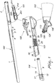
- the modular portable weapon comprises a supporting module, generally designated by the reference numeral 100, a locking and recocking module with swivel breech-lock and rotating locking head, designated by the reference numeral 101, a stock or handle module 102, and a containment module 103, which is suitable to contain a magazine module 104 and a cartridge lifting and firing mechanism module, generally designated by the reference numeral 105.
- the supporting module 100 is constituted by a barrel 1, which is provided with a sheath or barrel extension 2, and on which all the other modular components of the system are mounted.
- the locking and recocking module with swivel breech-lock and rotating locking head 101 is mounted inside the sheath or barrel extension itself and is capable of performing all the functions for locking, opening, case ejection and recocking with return to locking required for correct operation of the weapon. All the moving components for locking and opening the firing chamber of the weapon, the swivel breech-lock mass, the recoil spring, the breech-lock recovery spring, the ejector and the corresponding spring are contained within the barrel extension and are not arranged in a dissociated manner as in traditional weapons.
- the module 102 which constitutes the stock of the weapon, is mounted on the same supporting module formed by the barrel provided with a barrel extension.
- the stock or handle module can be of various kinds: pistol grip stock, stock with pistol handle, telescopic stock, et cetera, ensuring the possibility to easily obtain a weapon which is configured according to the various stock fitting requirements.
- the containment module 103 is engaged on the supporting module 100 and the magazine module 104 is mounted therein and can be easily separated from the weapon by virtue of the complete lack of threads that are normally present in traditional weapons.
- tubular magazines of different length ensures the possibility to easily have a weapon with a tubular magazine which contains a larger or smaller number of cartridges, depending on the various operating requirements.
- the containment module 103 has the triple function of a forestock for gripping the weapon with one's hand, of a frame as a component for containing the firing mechanism of the weapon and of the system for the exit and lifting of the cartridges of the magazine, and of trigger plate as a trigger protection component.
- This new component is simply engaged with the supporting module 100, which is formed by the barrel with its sheath or barrel extension, without requiring screws or threaded caps but only by means of claws which are formed on a sliding sleeve, which is mounted at the front inside it and through an interlocking coupling on a plate of the stock module which is rigidly coupled to the rear part of the sheath or barrel extension itself.
- the firing module 105 is mounted inside the containment module 103, at the trigger plate molded monolithically therein.
- the magazine module 104 is simply accommodated at the front, inside the containment module 103, and passes inside the sleeve that anchors it to the barrel. The magazine 103 is then engaged with the barrel.
- the supporting module 100 formed by the barrel 1 and by the barrel extension 2, has a block 3 which is welded to the barrel 1.
- the block 3 has a flat and elongated shape, which adheres snugly to the outer profile 4 of the barrel 1, so that it can be obtained both by welding and monolithically by machining the material of the barrel 1 itself.
- the block 3 which is welded to or formed from the barrel 1, is provided on both sides with two guides 5 and with a front slot 6, which as will become better apparent hereinafter are used to keep the modular portable weapon system assembled without requiring mutually screwed components.
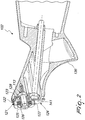
- the sheath or barrel extension 2 has such a length as to contain the entire locking and recocking module with swivel breech-lock and rotating locking head 101, and is provided at the rear with a coupling seat, constituted in the specific case by threaded sectors 7, for rapid engagement of the stock or handle module 102, which is provided with a corresponding quick engagement system.
- the quick engagement system of the stock or handle module 102 essentially includes an annular main body 121 which has threaded sectors 122, a cylindrical stem 123 for centering on the stock, and an internal seat for Belleville springs 125.
- a fastening nut 126 is provided with a shank which passes internally through both the Belleville springs 125 and the annular main body 121 to ensure the mounting of the Belleville springs 125 on the annular main body 121 by virtue of a snap ring 128 which engages on a seat thereof which is formed at the rear end of the shank of the fastening nut 126.
- the entire assembled annular main body 121 can thus be screwed freely, at least in the initial step, onto a threaded stem of a tension member 113 which is mounted on the stock.
- the quick coupling also offers the possibility to provide the stock or handle 102 with a given drop and cast with respect to the aiming line of the weapon by means of an adjustment member constituted by an abutment plate 124.
- the thickness of the plate 124 is conveniently determined in relation to the drop and cast that the stock must have with respect to the aiming line of the weapon.
- the thickness of the plate 124 is therefore different both when considered on its vertical axis and when considered on its horizontal axis.
- the stock module 102 is mounted to the supporting module on the barrel extension 2 of the module.
- the stock module 102 In order to assemble the stock module 102, complete with quick coupling, it is sufficient to arrange the stock module adjacent to the sheath or barrel extension 2, which has, as the rear, inside it, the threaded sectors 7, which are suitable to screw onto the corresponding threaded sectors 122 provided on the annular main body 121.
- Screwing occurs rapidly, inserting the entire annular main body 121 inside the barrel extension 2, taking care, during insertion, to align its threaded sectors 122 with recesses formed inside the barrel extension 2, the alignment being easily obtained by keeping, for example, the pistol grip of the stock 136 in a transverse position with respect to the vertical axis of the weapon, i.e., at 90°, and by then screwing together the threaded sectors 122 of the annular main body 121 with the respective threaded sectors 7 of the sheath or barrel extension 2, with a rotary motion of the stock which has a rotation end position determined automatically by the contact of a stroke limiter.
- the stock module 102 complete with quick coupling is correctly mounted on the weapon when, after rotation is completed, the pistol grip of the stock 136 is aligned with the vertical axis of the weapon.
- the drop and cast of the stock 102, provided by the plate 124, are determined when the entire stock module 102 is mounted on the supporting module 100.
- the quick coupling is assembled with the tension member 113 screwed onto the stock.
- the compression of the Belleville springs 125 is such as to ensure perfect adhesion between the stock module 102, the plate 124 and the annular main body 121 of the quick coupling.
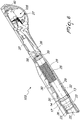
- Figure 3 is a view of the locking and recocking module with swivel breech-lock and rotating locking head 101, which is constituted by a single body which is completely accommodated within the sheath or barrel extension 2 and has a locking means, for locking the firing chamber of the weapon, an opening means, a case ejection means, and a recocking means with locking return.
- the locking and recocking module with swivel breech-lock and rotating locking head 101 comprises a swivel breech-lock 201, in which a breech-lock recoil spring is inserted and in which a rotating locking head 23 is mounted.
- the rotating locking head 203 is jointly connected to the breech-lock 201 by means of a head rotation pivot 204, which in order to concentrate the entire movable mass which is needed for the operation of the weapon on the breech-lock is jointly connected to the breech-lock and engages a helical cam, not shown in the figure, which is provided on the cylindrical shank of the locking head.
- the entire mass required for inertial operation of the weapon is concentrated exclusively on the swivel breech-lock 21 which, being accommodated within the sheath or barrel extension of the weapon, is the member onto which the components of the system are assembled.
- the rotating locking head 203 provides the locking and opening of the firing chamber of the weapon by a rotary motion determined by the helical cam, which is provided on its stem, with the contribution of helical inclined planes.
- the inclined planes mutually converge and are provided both on the rotating locking head and on the swivel breech-lock. The inclined planes prevent the possible bouncing of the swivel breech-lock when, during the locking action, it abuts against the spring of the inertial system.
- the module 101 includes an ejector module 208, which is inserted within a longitudinal seat formed on the swivel breech-lock.
- a guiding pin 209 is inserted in the ejector body 208 and is fastened to a spring guide pin anchoring plate 211, on which a damper 212, for cushioning the impact of the swivel breech-lock on its stroke limiter, a breech-lock abutment plate 213, on which the stroke of the swivel breech-lock indeed ends during opening, and an ejector spring 214 are mounted sequentially.
- the position of the ejector 208 on the locking and recocking module with swivel breech-lock and rotating locking head is such as to allow the ejector spring 214 to also operate as an auxiliary recoil spring, during the first step of locking the weapon, and allow the ejector spring guide pin 209 to guide laterally the cartridge during its lifting and insertion into the firing chamber of the weapon.
- a recoil spring guide pin 219 is inserted, through a hole, on the swivel breech-lock 201 and a recoil spring 220 is mounted at the rear on a suitable groove, and allows the swivel breech-lock 201 to return to the closed position.
- a firing pin 225 is mounted on the swivel breech-lock 201 and, inserted in the corresponding spring, which is not shown in the figure, passes through the rotating locking head 203, the head rotation pivot 204 and the breech-lock and is rigidly coupled to the latter by means of a retention pin 227.
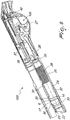
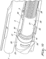
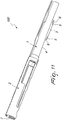
- the magazine module 104 comprises a tubular magazine 8, which has, at the front, seats 9 for snap rings and, in its rear end, a choked portion 10, which is suitable to stop a cartridge presser 11 which is inserted therein so as to provide a retainer for a magazine spring 12 without thereby preventing the insertion of the cartridges to load the weapon.
- a flange 13 provided with an annular portion 14, with two toothed sectors 15 and with a seat 16 for a stop button 17 with a corresponding return spring 18, is mounted onto the front part of the tubular magazine 8.
- a rod plug 20 is mounted on the flange 13, which is fixed to the tubular magazine 8 by virtue of the snap rings 19, through through slots 21 which engage the toothed sectors 15 of the flange 13.
- tubular magazines 8 of different length, a range of tubular magazines containing a different number of cartridges is made easily available to users.
- the entire magazine tube module 104 is accommodated within the containment module 103 without however being an integral part thereof, as shown more clearly in Figure 6 .
- the containment module 103 can be made of plastic material, by molding, without requiring metallic inserts or other reinforcement members.
- the containment module 103 comprises a portion 25 which acts as a forestock to grip the weapon with one's hand, a portion 26 which acts as a receiver for a containing the firing mechanism of the weapon and the system for actuating the cartridges that exit from the magazine, and a portion 27 which acts as a trigger plate, as a trigger protection member.
- a spring 28 is inserted within the forestock portion 25 and is adapted to draw an anchoring sleeve 29 which has claws 30 which engage the guides 5 of the block 3 of the barrel 1, constituting the system for engaging the containment module 103 with the supporting module 100.
- a slider 32 is engaged on a seat 31 of the anchoring sleeve 29 and is pushed with one's hand on its front plane 33 in order to retract the sleeve 29 and compress the spring 28.
- the fully assembled magazine tube module 104 is inserted in the sleeve 29 and the corresponding return spring 28 until the throttled part 10 of the tubular magazine 8 abuts against a stop tooth 35 of the containment module 103.
- the stop button 17 of the magazine module 104 interferes with a wall 36 of the containment module 103, preventing the magazine module 104 from being extracted inadvertently.
- the containment module 103 comprises a cartridge retention lever 37, which, by means of a front part 38 thereof, stops the cartridges within the magazine module 104 when the weapon is loaded.
- the portion of the receiver 26 of the containment module 103 accommodates the entire firing and cartridge feed mechanism, generally designated by the reference numeral 105, which is not described here since it is per se known.
- the supporting module 100 is already complete with a locking and recocking assembly with swivel breech-lock 101 mounted inside it and retained thereat by the stock module 102, engaged on the rear part of the sheath or barrel extension 2, it is sufficient to take the containment module 103, complete with all the components described above, and arrange a tab 40 thereof adjacent to the slot 141 formed in the plate 124 which belongs to the stock module until they are engaged in each other.
- the sleeve 29 is retracted and, by resting against the spring 28, compresses it, moving into such a position as to be able to align the entire containment module 103 on an axis which is substantially parallel to the barrel axis 1 or supporting module 100, keeping the claws 30 of the sleeve 29 in a retracted position with respect to the claws 5 provided on the block 3 which is welded or formed from the barrel 1, as shown more clearly in Figure 8 .
- the supporting module 100 also acts as a support for the cartridge retention lever 37 by virtue of the contact of its plane 43 with the respective plane 44 of the sheath or barrel extension.
- Figure 10 is a detail view of the sleeve 29 with its claws 30 engaged on the respective guides 5 of the block 3 welded or provided from the barrel 1.
- the modular weapon comprises a single supporting module, which is constituted by the barrel and by the sheath or barrel extension, to which it is possible to apply the other modules without using additional members.
- the stresses produced by the firing of the cartridge during use of the weapon are discharged mainly onto the supporting module.
- All the components of the weapon are part of a modular system with mutually independent modules, each capable of performing its own function and all manually engageable with each other, without requiring tools for the final assembly of the weapon, allowing the user also to choose, among the commercially available modules, supporting modules with barrels of different lengths and different sight type, stock modules with different types of grip, tubular magazine modules which contain mutually different numbers of cartridges, the one that complies best with his requirements.
- the modular portable weapon according to the present invention in fact arranges in an entirely innovative manner the main components that are traditionally present in a portable weapon, such as a smoothbore or rifled-bore rifle, attributing even different functions to these components.
- the modular portable weapon according to the present invention is constructively simple and has a reduced number of components with respect to traditional weapons.
- the supporting module formed by the barrel with its sheath or barrel extension, is provided with a locking and recocking module with swivel breech-lock and rotating locking head, which is mounted within the sheath or barrel extension itself and is capable of performing all the functions for locking, opening, case ejection and recocking with return to locking, which are required for correct operation of the weapon.
- the module that constitutes the stock of the weapon is mounted on the same supporting module formed by the barrel provided with a sheath or barrel extension by means of a quick coupling which has a drop and cast which can be obtained automatically upon its engagement on the sheath.
- various modules with various types of stock such as pistol grip stocks, pistol handle stocks, telescopic stocks, et cetera, ensures the possibility to obtain easily a weapon which is configured according to the various stock mounting requirements.
- Such other module is constituted by a tubular magazine which, without requiring disassembly of its internal components, can be easily separated from the weapon by virtue of the complete lack of the threads that are normally present in traditional weapons.
- tubular magazines of different lengths ensures the possibility to easily have a weapon with a tubular magazine which contains a larger or smaller number of cartridges depending on the various requirements of use.
- the supporting module according to the present invention has allowed to avoid the need to have, as in traditional weapons, members such as the frame or receiver made of steel or light alloy, the magazine tube rigidly coupled thereto and the locking cap of the entire receiver-barrel-forestock system of the weapon, and it has been possible to provide monolithically, by molding plastic material without requiring metallic inserts embedded internally or other reinforcement members, a new component, the containment module, which has the triple function of a forestock for gripping the weapon with one's hand, of a receiver as a member for containing the firing mechanism of the weapon, and of the exit and lifting actuation system of the cartridges of the magazine and of a trigger plate as a trigger protection member.
- This new component, the containment module is simply engaged with the supporting module formed by the barrel with its sheath or barrel extension, without requiring screws or threaded caps but exclusively by means of the claws provided on a sliding sleeve which is mounted at the front inside it and through an interlocking on a plate of the stock module which is rigidly coupled to the rear part of the sheath or barrel extension.
- the present invention provides a portable weapon which allows to consider the weapon no longer as a set of components which are generally assembled into subassemblies which in turn are assembled until two essential parts of the weapon are obtained, such as the barrel assembly and the receiver assembly, but as a set of independent modular parts, each capable of performing a function of its own, and all of which can be assembled together without requiring tools.
- the modular portable weapon according to the present invention therefore allows the end user to compose the weapon by choosing for example a type of barrel, stock or tubular magazine among the alternatives provided commercially, with the characteristics that are best suited to his requirements.
Landscapes
- Engineering & Computer Science (AREA)
- General Engineering & Computer Science (AREA)
- Toys (AREA)
- Portable Nailing Machines And Staplers (AREA)
- Casings For Electric Apparatus (AREA)
- Respiratory Apparatuses And Protective Means (AREA)
- Aiming, Guidance, Guns With A Light Source, Armor, Camouflage, And Targets (AREA)
- Adornments (AREA)
- Air Bags (AREA)
Claims (21)
- Arme modulaire portable comprenant un module (100) constitué par le canon (1) de l'arme et un ou plusieurs modules (101, 102, 103, 104, 105) opérationnellement indépendants les uns des autres et associés audit module de support (100); caractérisée en ce que(1) présente un manchon ou extension de canon (2); lesdits un ou plusieurs modules incluant un module de verrouillage et de réarmement (101) apte à être inséré dans ledit manchon ou extension de canon (2) et contenu dans celui-ci; un module de crosse ou de poignée (102) directement connectable à une extrémité arrière dudit manchon ou extension de canon (2), un module de confinement (103) directement connectable audit canon (1) à un emplacement situé à l'avant dudit manchon ou extension de canon (2), un module de magasin (104) et un module de mécanisme de levage et de tir de cartouche (105), ledit module de verrouillage et de réarmement (101) incluant un verrou de culasse (101) et une tête de verrouillage (23), ledit module de mécanisme de levage et de tir de cartouche (105) étant reçu substantiellement entièrement dans une partie de réception (26) dudit module de confinement (103).
- Arme modulaire portable selon la revendication 1, caractérisée en ce que ledit module de verrouillage et de réarmement (101) est configuré pour mettre en oeuvre les fonctions de verrouillage et d'ouverture de la chambre, d'éjection de la douille, et de réarmement avec retour au verrouillage, nécessaires à l'actionnement de l'arme.
- Arme modulaire portable selon la revendication 1, caractérisée en ce que ledit module de crosse ou de poignée (102) est associé audit module de support (100) par un raccord rapide (121, 122, 123, 125, 126).
- Arme modulaire portable selon la revendication 1, caractérisée en ce que ledit module de confinement (103) est configuré de manière à contenir ledit module de magasin (104) et ledit module de mécanisme de chargement et de tir de cartouche (105).
- Arme modulaire portable selon la revendication 2, caractérisée en ce que ledit canon (1) est vissé sur ledit manchon ou extension de canon (2).
- Arme modulaire portable selon la revendication 5, caractérisée en ce que ledit module de support (100) comprend une moyen d'association; ledit moyen d'association comprend un raccord (7) pour ledit module de crosse (102) et un raccord pour ledit module de confinement, ledit raccord pour ledit module de confinement comprenant un bloc (3).
- Arme modulaire portable selon une ou plusieurs des revendications précédentes, caractérisée en ce que ledit bloc (3) a une forme plate et allongée qui adhère fortement au profil extérieur (4) dudit canon (1), de sorte qu'il peut être obtenu à la fois par soudage et de manière monolithique par usinage du matériau dudit canon (1).
- Arme modulaire portable selon une ou plusieurs des revendications précédentes, caractérisée en ce que ledit bloc (3) est pourvu des deux côtés avec deux guidages (5) et avec une fente avant (6) qui sont adaptés pour entrer en engagement avec des griffes (30) dudit module de confinement (103), formant ainsi un système pour mettre le module de confinement (103) en engagement avec le module de support (100).
- Arme modulaire portable selon une ou plusieurs des revendications précédentes, caractérisée en ce que ledit module de crosse (102) est associée avec ledit module de support (100) par un élément (124) pour ajuster la pente et la déviation de la crosse (102).
- Arme modulaire portable selon une ou plusieurs des revendications précédentes, caractérisée en ce que ledit module de verrouillage et de réarmement (101) comprend un verrou de culasse pivotant (201) qui est constitué d'un corps unique qui est entièrement reçu dans ledit manchon ou extension de canon (2); un ressort de recul de verrou de culasse est inséré dans ledit verrou de culasse pivotant (201) et une tête de verrouillage rotative (23) est montée dans celui-ci; ladite tête de verrouillage rotative (23) est couplée de manière rigide avec ledit verrou de culasse (201) par un pivot de rotation de la tête (204) qui est couplé de manière rigide avec ledit verrou de culasse (201) et entre en engagement avec une came hélicoïdale formée sur un marche cylindrique de ladite tête de verrouillage; la masse totale nécessaire au fonctionnement inertiel de l'arme est concentrée exclusivement au niveau dudit verrou de culasse pivotant (201).
- Arme modulaire portable selon un ou plusieurs des revendications précédentes, caractérisée en ce que ledit module de verrouillage et de réarmement (101) comprend un corps d'éjection (208) qui est inséré dans un siège longitudinal formé dans ledit verrou de culasse pivotant (201); une broche de guidage (209) est insérée dans le corps d'éjection (208) et est fixée à une plaque d'ancrage de broche de guidage de ressort (211) sur laquelle un amortisseur (212) pour amortir l'impact du verrou de culasse pivotant (201) sur son limiteur de course, une plaque de butée de verrou de culasse (213) sur laquelle se termine la course du verrou de culasse pivotant (201) lors de l'ouverture, et un ressort d'éjection (214) sont montés séquentiellement; la position dudit éjecteur (208) sur le module de verrouillage et de réarmement avec le verrou de culasse pivotant et la tête de verrouillage rotative est telle qu'elle permet au ressort d'éjection (214) de fonctionner également comme un ressort récupérateur auxiliaire, pendant la première étape du verrouillage, et qu'elle permet la broche de guidage du ressort d'éjection (209) de guider la cartouche latéralement lorsqu'elle est soulevée et insérée dans la chambre de l'arme; en outre, une broche de guidage de ressort de récupération (219) est insérée dans le verrou de culasse pivotant (201) à travers un trou et un ressort de récupération (220) est monté à l'arrière sur un renfoncement, ledit ressort (220) permettant au verrou de culasse pivotant (201) de retourner dans la position fermée; une broche de tir (225) est en outre montée sur le verrou de culasse pivotant (201) et lorsqu'elle est insérée dans un ressort correspondant, passe à travers la tête de verrouillage rotative (203), le pivot de rotation de la tête (204) et le verrou de culasse (201) lui-même, et est couplée de manière rigide à ce-dernier (201) par une broche de retenue (227).
- Arme modulaire portable selon un ou plusieurs des revendications précédentes, caractérisée en ce que ledit module de magasin (104) comprend un magasin tubulaire (8) qui présente, à l'avant, des sièges (9) pour des anneaux élastiques à section constante et, à son extrémité arrière, une partie étranglée (10) qui est apte à arrêter un poussoir de cartouche (11) qui est insérée dans celle-ci de manière à fournir un dispositif de retenue pour un ressort de magasin (12) sans empêcher l'insertion des cartouches pour charger l'arme; une bride (13) pourvue d'un élément annulaire (14) est montée sur la partie avant dudit magasin tubulaire (8) et présente deux secteurs dentés (15) et un siège (16) pour un bouton d'arrêt (17) avec un ressort de rappel correspondant (18); un tampon en forme de tige (20) est monté sur ladite bride (13), qui est fixée au magasin tubulaire (8) par des anneaux élastiques à section constante (19), à travers des fentes (21) qui entrent en engagement avec les secteurs dentés (15) de la bride (13); un tampon de magasin (22), qui est inséré dans le tampon en forme de tige (20) et est verrouillé au moyen d'une vis (23), permet un nettoyage interne du magasin tubulaire (8).
- Arme modulaire portable selon une ou plusieurs des revendications précédentes, caractérisée en ce que ledit module de confinement (103) est réalisé en une matière plastique, par moulage, sans inserts métalliques ou autre élément de reinforcement.
- Arme modulaire portable selon une ou plusieurs des revendications précédentes, caractérisée en ce quel ledit module de confinement (103) comprend une partie (25) qui sert de garde-main pour saisir l'arme avec la main, une partie (26) qui sert de réceptacle destiné à contenir le mécanisme de tir de l'arme et le système d'actionnement des cartouches qui sortent dudit magasin, et une partie (27) qui sert de plaque de détente, d'élément de protection de la détente.
- Arme modulaire portable selon une ou plusieurs des revendications précédentes, caractérisée en ce que un ressort (28) est inséré dans ledit garde-main (25) et tire un manchon d'ancrage (29) qui présente des griffes (30) aptes à entrer en engagement avec lesdits guidages (5) dudit bloc (3) du canon, formant ainsi le système pour mettre le module de confinement (103) en engagement avec le module de support (100).
- Arme modulaire portable selon une ou plusieurs des revendications précédentes, caractérisée en ce que une glissière (32) est engagée dans un siège (31) dudit manchon d'ancrage (29) et est adaptée pour être poussée manuellement sur un plane frontal (33) de celui-ci afin de rétracter ledit manchon (29) et comprimer ledit ressort (28).
- Arme modulaire portable selon une ou plusieurs des revendications précédentes, caractérisée en ce que ledit module de magasin (104) entièrement assemblé est inséré dans ledit manchon (29) et le ressort de rappel (28) correspondant jusqu'à ce que la partie étranglée (10) du magasin tubulaire (8) bute contre une dent d'arrêt (35) du module de confinement (103) ; dans cette position le bouton d'arrêt (17) du module de magasin (104) interfère avec une paroi (36) du module de confinement (103), empêchant ainsi ledit module de magasin (104) de se désengager par inadvertance.
- Arme modulaire portable selon une ou plusieurs des revendications précédentes, caractérisée en ce que ledit module de confinement (103) comprend un levier de retenue de cartouche (37) qui, avec sa partie avant (38), arrête les cartouches dans le module de magasin (104) lorsque l'arme est chargée.
- Arme modulaire portable selon une ou plusieurs des revendications précédentes, caractérisée en ce que la partie de réception (26) du module de confinement (103) abrite la totalité dudit mécanisme de chargement et de tir (105).
- Arme modulaire portable selon une ou plusieurs des revendications précédentes, caractérisée en ce que ladite arme est entièrement assemblée en mettant lesdits modules (100, 101, 102, 103, 104, 105) desquels l'arme est composée en engagement les uns avec les autres sans nécessiter d'éléments supplémentaires et sans l'aide d'outils.
- Arme modulaire portable selon une ou plusieurs des revendications précédentes, caractérisée en ce que ledit bloc (3) dudit canon (1) comprend une fente avant (6) dans laquelle s'engage une partie annulaire (14) de ladite bride (13) du module de magasin (102).
Applications Claiming Priority (1)
| Application Number | Priority Date | Filing Date | Title |
|---|---|---|---|
| IT001473A ITMI20071473A1 (it) | 2007-07-20 | 2007-07-20 | Arma portatile modulare |
Publications (3)
| Publication Number | Publication Date |
|---|---|
| EP2017564A2 EP2017564A2 (fr) | 2009-01-21 |
| EP2017564A3 EP2017564A3 (fr) | 2015-03-11 |
| EP2017564B1 true EP2017564B1 (fr) | 2017-06-28 |
Family
ID=39865450
Family Applications (1)
| Application Number | Title | Priority Date | Filing Date |
|---|---|---|---|
| EP08012288.0A Active EP2017564B1 (fr) | 2007-07-20 | 2008-07-08 | Arme portable modulaire |
Country Status (10)
| Country | Link |
|---|---|
| US (1) | US8230632B2 (fr) |
| EP (1) | EP2017564B1 (fr) |
| JP (1) | JP5362279B2 (fr) |
| CN (1) | CN101458051B (fr) |
| BR (1) | BRPI0803529B1 (fr) |
| EA (1) | EA017634B1 (fr) |
| ES (1) | ES2634640T3 (fr) |
| IL (1) | IL192754A (fr) |
| IT (1) | ITMI20071473A1 (fr) |
| MX (1) | MX2008009337A (fr) |
Cited By (1)
| Publication number | Priority date | Publication date | Assignee | Title |
|---|---|---|---|---|
| RU209491U1 (ru) * | 2021-09-30 | 2022-03-16 | Александр Иванович Лейком | Корпус спускового механизма стрелкового оружия |
Families Citing this family (24)
| Publication number | Priority date | Publication date | Assignee | Title |
|---|---|---|---|---|
| FI116697B (fi) * | 2004-07-07 | 2006-01-31 | Sako Oy | Vaihtopiippuase |
| AT502344B1 (de) * | 2005-09-14 | 2007-12-15 | Steyr Mannlicher Holding Gmbh | Gehäuse für ein gewehr |
| ITMI20071472A1 (it) * | 2007-07-20 | 2009-01-21 | Benelli Armi Spa | Attacco ad innesto rapido, particolarmente per il calcio di un'arma portatile |
| CN102741906B (zh) | 2010-01-29 | 2016-06-08 | 艾利丹尼森公司 | 智能标识系统应用中使用的rfid/nfc板和/或阵列及其使用方法 |
| BR112013018021B1 (pt) * | 2011-01-17 | 2021-08-10 | Sako Oy | Arma de fogo e sistema de arma de fogo |
| US9766029B2 (en) | 2011-07-12 | 2017-09-19 | Cadex, Inc. | Detachable chassis base for rifle |
| EP2943733B1 (fr) | 2013-01-10 | 2019-02-27 | Sturm, Ruger & Company, Inc. | Système de crosse interchangeable pour armes à feu |
| US9151552B2 (en) | 2013-03-15 | 2015-10-06 | Christos Stratis Gryparis | Lock interface insert for machine gun bolt assembly |
| US9534859B2 (en) | 2014-05-05 | 2017-01-03 | Vincent P. Battaglia | Precision bolt action semiautomatic rifle |
| US9429387B1 (en) | 2015-03-20 | 2016-08-30 | Magpul Industries Corp. | Modular stock for a firearm |
| US9322611B1 (en) | 2015-03-20 | 2016-04-26 | Magpul Industries Corp. | Modular stock for a firearm |
| KR102283348B1 (ko) * | 2015-05-12 | 2021-07-29 | 가부시키가이샤 도쿄 마루이 | 배럴 장착용 센터링 장치 |
| CN105444617A (zh) * | 2015-12-17 | 2016-03-30 | 浙江新华体育器材制造有限公司 | 一种拆卸式气枪 |
| CN105486170B (zh) * | 2016-01-07 | 2017-09-26 | 日照兄弟机械有限公司 | 一种猎枪 |
| CN105486166B (zh) * | 2016-01-19 | 2017-05-31 | 日照兄弟机械有限公司 | 一种枪支装配机 |
| EP3205702A1 (fr) | 2016-02-11 | 2017-08-16 | Bp Oil International Limited | Compositions de carburant avec des additifs |
| US11879700B2 (en) | 2016-12-19 | 2024-01-23 | Savage Arms, Inc. | Semi-automatic shotgun and components thereof |
| WO2018119006A1 (fr) | 2016-12-19 | 2018-06-28 | Vista Outdoor Operations Llc | Fusil de chasse semi-automatique et composants associés |
| WO2018117990A1 (fr) * | 2016-12-23 | 2018-06-28 | Bahtiyar Tasyagan | Mécanisme de culasse actionné par recul comprenant un support de boulon et un boulon rotatif, et assurant une commodité d'assemblage et de désassemblage |
| US10345076B2 (en) | 2017-03-07 | 2019-07-09 | Magpul Industries Corp. | Firearm barrel tray, stock, and related methods |
| USD844735S1 (en) | 2017-03-07 | 2019-04-02 | Magpul Industries Corp. | Firearm stock |
| RU2725113C1 (ru) * | 2020-01-14 | 2020-06-29 | Максим Сергеевич Турлаков | Винтовка турлакова n 7 (галина) |
| US11193724B1 (en) | 2020-10-23 | 2021-12-07 | Brent McCarthy | Hybrid pistol frame kit for receiving firearm parts and accessories |
| CN113458744B (zh) * | 2021-06-21 | 2024-05-31 | 国网安徽省电力有限公司 | 一种套筒辅助更换匣以及应用该辅助更换匣的检修机器人 |
Family Cites Families (22)
| Publication number | Priority date | Publication date | Assignee | Title |
|---|---|---|---|---|
| DE1271598B (de) * | 1964-10-29 | 1968-06-27 | Rheinmetall Gmbh | Aus Baugruppen zusammengesetzte automatische Waffe |
| US4087930A (en) * | 1976-10-20 | 1978-05-09 | O. F. Mossberg & Sons, Inc. | Magazine cap retaining means for tubular magazine firearms |
| US4615132A (en) * | 1983-03-28 | 1986-10-07 | Smith David E | Self loading pistol having a rear sight which secures a detachable breech block insert |
| US4644930A (en) * | 1984-07-18 | 1987-02-24 | Robert Mainhardt | Gun for firing a variety of projectiles |
| US4878308A (en) * | 1989-04-17 | 1989-11-07 | Browning Corporation | Adjustable shotgun rib |
| US6484430B1 (en) * | 1999-01-27 | 2002-11-26 | Zdf Import/Export, Inc. | Multi-lugged bolt carrier and barrel for rifles |
| US6293040B1 (en) * | 1999-08-27 | 2001-09-25 | Defense Procurement Manufacturing Services, Inc. | Interchangeable weapon receiver for alternate ammunition |
| US6487805B1 (en) * | 2000-05-19 | 2002-12-03 | Armalite, Inc. | Firearm assembly |
| RU2202089C2 (ru) * | 2001-05-10 | 2003-04-10 | Государственное унитарное предприятие "Конструкторское бюро приборостроения" | Автоматическое стрелковое оружие |
| DE10205503C1 (de) * | 2002-02-09 | 2003-07-10 | Manfred Orth | Gewehr, umfassend einen Hinterschaft, einen Vorderschaft und einen Lauf |
| US6971202B2 (en) * | 2003-01-27 | 2005-12-06 | Terrence Bender | Gas operated action for auto-loading firearms |
| UY3970U (es) * | 2003-08-15 | 2005-03-31 | Juan Francisco Mauton Medvedeo | Nuevo diseno de arma semiautomatica para sistema de carga de cartuchos de tubos multiples para armas largas |
| US7971379B2 (en) * | 2004-02-13 | 2011-07-05 | Rmdi, Llc | Firearm |
| US7458179B2 (en) * | 2004-03-26 | 2008-12-02 | Swan Richard E | Modular panel system for attaching accessories to a firearm rail system |
| US8051595B2 (en) * | 2004-06-16 | 2011-11-08 | Colt Defense, Llc | Automatic or semi-automatic rifle |
| US7131228B2 (en) * | 2004-06-16 | 2006-11-07 | Colt Defense Llc | Modular firearm |
| RU2256137C1 (ru) * | 2004-06-17 | 2005-07-10 | Открытое акционерное общество "Тульский оружейный завод" | Устройство крепления элементов стрелкового оружия |
| US7428795B2 (en) * | 2005-02-11 | 2008-09-30 | Herring Geoffrey A | Receiver for firearm |
| AT502407B1 (de) * | 2005-09-14 | 2007-03-15 | Steyr Mannlicher Holding Gmbh | Gewehr |
| AT502344B1 (de) * | 2005-09-14 | 2007-12-15 | Steyr Mannlicher Holding Gmbh | Gehäuse für ein gewehr |
| US20070089347A1 (en) * | 2005-10-20 | 2007-04-26 | Webber Kevin A | Easy connect stock and forend system |
| US8056280B2 (en) * | 2008-09-23 | 2011-11-15 | Browning | Firearm having an improved forearm fastening mechanism |
-
2007
- 2007-07-20 IT IT001473A patent/ITMI20071473A1/it unknown
-
2008
- 2008-07-08 EP EP08012288.0A patent/EP2017564B1/fr active Active
- 2008-07-08 US US12/217,774 patent/US8230632B2/en active Active
- 2008-07-08 ES ES08012288.0T patent/ES2634640T3/es active Active
- 2008-07-10 IL IL192754A patent/IL192754A/en active IP Right Grant
- 2008-07-18 CN CN2008101847594A patent/CN101458051B/zh active Active
- 2008-07-18 EA EA200801577A patent/EA017634B1/ru unknown
- 2008-07-18 MX MX2008009337A patent/MX2008009337A/es active IP Right Grant
- 2008-07-18 JP JP2008187618A patent/JP5362279B2/ja active Active
- 2008-07-21 BR BRPI0803529-6A patent/BRPI0803529B1/pt active IP Right Grant
Cited By (1)
| Publication number | Priority date | Publication date | Assignee | Title |
|---|---|---|---|---|
| RU209491U1 (ru) * | 2021-09-30 | 2022-03-16 | Александр Иванович Лейком | Корпус спускового механизма стрелкового оружия |
Also Published As
| Publication number | Publication date |
|---|---|
| MX2008009337A (es) | 2009-03-05 |
| IL192754A0 (en) | 2009-02-11 |
| CN101458051A (zh) | 2009-06-17 |
| ITMI20071473A1 (it) | 2009-01-21 |
| EP2017564A2 (fr) | 2009-01-21 |
| EA200801577A1 (ru) | 2010-02-26 |
| EA017634B1 (ru) | 2013-02-28 |
| EP2017564A3 (fr) | 2015-03-11 |
| CN101458051B (zh) | 2013-05-15 |
| US8230632B2 (en) | 2012-07-31 |
| ES2634640T3 (es) | 2017-09-28 |
| JP2009041901A (ja) | 2009-02-26 |
| US20090019755A1 (en) | 2009-01-22 |
| JP5362279B2 (ja) | 2013-12-11 |
| BRPI0803529A2 (pt) | 2009-10-20 |
| IL192754A (en) | 2013-10-31 |
| BRPI0803529B1 (pt) | 2020-10-20 |
Similar Documents
| Publication | Publication Date | Title |
|---|---|---|
| EP2017564B1 (fr) | Arme portable modulaire | |
| US8141287B2 (en) | Lightweight, low cost semi-automatic rifle | |
| US9777982B2 (en) | Shrouded barrel and sight for revolver | |
| US10101109B2 (en) | Submachine gun conversion unit | |
| US20140360076A1 (en) | Bullpup stock kit for a rifle | |
| US20050262752A1 (en) | Firearm | |
| US20160146558A1 (en) | Conversion set for a firearm and method for converting a firearm | |
| US11112199B2 (en) | Slide action rifle with a bolt carrier locking mechanism external to the receiver | |
| US11486664B2 (en) | Configurable blowback bolt system | |
| AU2018328046B2 (en) | Machine gun | |
| AU2018328050B2 (en) | Machine gun | |
| AU2018328047B2 (en) | Machine gun | |
| US11713936B1 (en) | Fixed-to-tilted silencer adaptor for three-lug attachments | |
| US7275342B2 (en) | Semi-automatic weapon for several tubes cartridges loading system for long guns | |
| AU2018328049B2 (en) | Machine gun | |
| GB2163840A (en) | Pistol |
Legal Events
| Date | Code | Title | Description |
|---|---|---|---|
| PUAI | Public reference made under article 153(3) epc to a published international application that has entered the european phase |
Free format text: ORIGINAL CODE: 0009012 |
|
| AK | Designated contracting states |
Kind code of ref document: A2 Designated state(s): AT BE BG CH CY CZ DE DK EE ES FI FR GB GR HR HU IE IS IT LI LT LU LV MC MT NL NO PL PT RO SE SI SK TR |
|
| AX | Request for extension of the european patent |
Extension state: AL BA MK RS |
|
| REG | Reference to a national code |
Ref country code: HK Ref legal event code: DE Ref document number: 1123349 Country of ref document: HK |
|
| PUAL | Search report despatched |
Free format text: ORIGINAL CODE: 0009013 |
|
| AK | Designated contracting states |
Kind code of ref document: A3 Designated state(s): AT BE BG CH CY CZ DE DK EE ES FI FR GB GR HR HU IE IS IT LI LT LU LV MC MT NL NO PL PT RO SE SI SK TR |
|
| AX | Request for extension of the european patent |
Extension state: AL BA MK RS |
|
| RIC1 | Information provided on ipc code assigned before grant |
Ipc: F41A 11/02 20060101ALI20150204BHEP Ipc: F41A 3/72 20060101ALI20150204BHEP Ipc: F41A 15/12 20060101ALI20150204BHEP Ipc: F41A 9/18 20060101ALI20150204BHEP Ipc: F41C 23/20 20060101ALI20150204BHEP Ipc: F41A 3/26 20060101AFI20150204BHEP Ipc: F41A 25/12 20060101ALI20150204BHEP Ipc: F41A 11/00 20060101ALI20150204BHEP Ipc: F41A 9/72 20060101ALI20150204BHEP Ipc: F41A 21/48 20060101ALI20150204BHEP Ipc: F41A 3/66 20060101ALI20150204BHEP |
|
| RIN1 | Information on inventor provided before grant (corrected) |
Inventor name: MORETTI, LUIGI |
|
| 17P | Request for examination filed |
Effective date: 20150512 |
|
| RBV | Designated contracting states (corrected) |
Designated state(s): AT BE BG CH CY CZ DE DK EE ES FI FR GB GR HR HU IE IS IT LI LT LU LV MC MT NL NO PL PT RO SE SI SK TR |
|
| AKX | Designation fees paid |
Designated state(s): AT BE BG CH CY CZ DE DK EE ES FI FR GB GR HR HU IE IS IT LI LT LU LV MC MT NL NO PL PT RO SE SI SK TR |
|
| AXX | Extension fees paid |
Extension state: BA Extension state: AL Extension state: RS Extension state: MK |
|
| 17Q | First examination report despatched |
Effective date: 20160617 |
|
| GRAP | Despatch of communication of intention to grant a patent |
Free format text: ORIGINAL CODE: EPIDOSNIGR1 |
|
| INTG | Intention to grant announced |
Effective date: 20170127 |
|
| RAP1 | Party data changed (applicant data changed or rights of an application transferred) |
Owner name: BENELLI ARMI S.P.A. |
|
| GRAS | Grant fee paid |
Free format text: ORIGINAL CODE: EPIDOSNIGR3 |
|
| GRAA | (expected) grant |
Free format text: ORIGINAL CODE: 0009210 |
|
| AK | Designated contracting states |
Kind code of ref document: B1 Designated state(s): AT BE BG CH CY CZ DE DK EE ES FI FR GB GR HR HU IE IS IT LI LT LU LV MC MT NL NO PL PT RO SE SI SK TR |
|
| REG | Reference to a national code |
Ref country code: GB Ref legal event code: FG4D |
|
| REG | Reference to a national code |
Ref country code: CH Ref legal event code: EP |
|
| REG | Reference to a national code |
Ref country code: FR Ref legal event code: PLFP Year of fee payment: 10 |
|
| REG | Reference to a national code |
Ref country code: AT Ref legal event code: REF Ref document number: 905263 Country of ref document: AT Kind code of ref document: T Effective date: 20170715 |
|
| REG | Reference to a national code |
Ref country code: IE Ref legal event code: FG4D |
|
| REG | Reference to a national code |
Ref country code: DE Ref legal event code: R096 Ref document number: 602008050839 Country of ref document: DE |
|
| GRAT | Correction requested after decision to grant or after decision to maintain patent in amended form |
Free format text: ORIGINAL CODE: EPIDOSNCDEC |
|
| REG | Reference to a national code |
Ref country code: ES Ref legal event code: FG2A Ref document number: 2634640 Country of ref document: ES Kind code of ref document: T3 Effective date: 20170928 |
|
| PG25 | Lapsed in a contracting state [announced via postgrant information from national office to epo] |
Ref country code: HR Free format text: LAPSE BECAUSE OF FAILURE TO SUBMIT A TRANSLATION OF THE DESCRIPTION OR TO PAY THE FEE WITHIN THE PRESCRIBED TIME-LIMIT Effective date: 20170628 Ref country code: GR Free format text: LAPSE BECAUSE OF FAILURE TO SUBMIT A TRANSLATION OF THE DESCRIPTION OR TO PAY THE FEE WITHIN THE PRESCRIBED TIME-LIMIT Effective date: 20170929 Ref country code: NO Free format text: LAPSE BECAUSE OF FAILURE TO SUBMIT A TRANSLATION OF THE DESCRIPTION OR TO PAY THE FEE WITHIN THE PRESCRIBED TIME-LIMIT Effective date: 20170928 Ref country code: LT Free format text: LAPSE BECAUSE OF FAILURE TO SUBMIT A TRANSLATION OF THE DESCRIPTION OR TO PAY THE FEE WITHIN THE PRESCRIBED TIME-LIMIT Effective date: 20170628 Ref country code: FI Free format text: LAPSE BECAUSE OF FAILURE TO SUBMIT A TRANSLATION OF THE DESCRIPTION OR TO PAY THE FEE WITHIN THE PRESCRIBED TIME-LIMIT Effective date: 20170628 |
|
| REG | Reference to a national code |
Ref country code: NL Ref legal event code: MP Effective date: 20170628 |
|
| REG | Reference to a national code |
Ref country code: LT Ref legal event code: MG4D |
|
| REG | Reference to a national code |
Ref country code: AT Ref legal event code: MK05 Ref document number: 905263 Country of ref document: AT Kind code of ref document: T Effective date: 20170628 |
|
| PG25 | Lapsed in a contracting state [announced via postgrant information from national office to epo] |
Ref country code: BG Free format text: LAPSE BECAUSE OF FAILURE TO SUBMIT A TRANSLATION OF THE DESCRIPTION OR TO PAY THE FEE WITHIN THE PRESCRIBED TIME-LIMIT Effective date: 20170928 Ref country code: LV Free format text: LAPSE BECAUSE OF FAILURE TO SUBMIT A TRANSLATION OF THE DESCRIPTION OR TO PAY THE FEE WITHIN THE PRESCRIBED TIME-LIMIT Effective date: 20170628 Ref country code: SE Free format text: LAPSE BECAUSE OF FAILURE TO SUBMIT A TRANSLATION OF THE DESCRIPTION OR TO PAY THE FEE WITHIN THE PRESCRIBED TIME-LIMIT Effective date: 20170628 Ref country code: NL Free format text: LAPSE BECAUSE OF FAILURE TO SUBMIT A TRANSLATION OF THE DESCRIPTION OR TO PAY THE FEE WITHIN THE PRESCRIBED TIME-LIMIT Effective date: 20170628 |
|
| PG25 | Lapsed in a contracting state [announced via postgrant information from national office to epo] |
Ref country code: CZ Free format text: LAPSE BECAUSE OF FAILURE TO SUBMIT A TRANSLATION OF THE DESCRIPTION OR TO PAY THE FEE WITHIN THE PRESCRIBED TIME-LIMIT Effective date: 20170628 Ref country code: RO Free format text: LAPSE BECAUSE OF FAILURE TO SUBMIT A TRANSLATION OF THE DESCRIPTION OR TO PAY THE FEE WITHIN THE PRESCRIBED TIME-LIMIT Effective date: 20170628 Ref country code: EE Free format text: LAPSE BECAUSE OF FAILURE TO SUBMIT A TRANSLATION OF THE DESCRIPTION OR TO PAY THE FEE WITHIN THE PRESCRIBED TIME-LIMIT Effective date: 20170628 Ref country code: AT Free format text: LAPSE BECAUSE OF FAILURE TO SUBMIT A TRANSLATION OF THE DESCRIPTION OR TO PAY THE FEE WITHIN THE PRESCRIBED TIME-LIMIT Effective date: 20170628 Ref country code: SK Free format text: LAPSE BECAUSE OF FAILURE TO SUBMIT A TRANSLATION OF THE DESCRIPTION OR TO PAY THE FEE WITHIN THE PRESCRIBED TIME-LIMIT Effective date: 20170628 |
|
| REG | Reference to a national code |
Ref country code: DE Ref legal event code: R119 Ref document number: 602008050839 Country of ref document: DE |
|
| PG25 | Lapsed in a contracting state [announced via postgrant information from national office to epo] |
Ref country code: IS Free format text: LAPSE BECAUSE OF FAILURE TO SUBMIT A TRANSLATION OF THE DESCRIPTION OR TO PAY THE FEE WITHIN THE PRESCRIBED TIME-LIMIT Effective date: 20171028 Ref country code: PL Free format text: LAPSE BECAUSE OF FAILURE TO SUBMIT A TRANSLATION OF THE DESCRIPTION OR TO PAY THE FEE WITHIN THE PRESCRIBED TIME-LIMIT Effective date: 20170628 |
|
| REG | Reference to a national code |
Ref country code: CH Ref legal event code: PL |
|
| REG | Reference to a national code |
Ref country code: HK Ref legal event code: GR Ref document number: 1123349 Country of ref document: HK |
|
| PG25 | Lapsed in a contracting state [announced via postgrant information from national office to epo] |
Ref country code: MC Free format text: LAPSE BECAUSE OF FAILURE TO SUBMIT A TRANSLATION OF THE DESCRIPTION OR TO PAY THE FEE WITHIN THE PRESCRIBED TIME-LIMIT Effective date: 20170628 |
|
| REG | Reference to a national code |
Ref country code: IE Ref legal event code: MM4A |
|
| PG25 | Lapsed in a contracting state [announced via postgrant information from national office to epo] |
Ref country code: DK Free format text: LAPSE BECAUSE OF FAILURE TO SUBMIT A TRANSLATION OF THE DESCRIPTION OR TO PAY THE FEE WITHIN THE PRESCRIBED TIME-LIMIT Effective date: 20170628 Ref country code: DE Free format text: LAPSE BECAUSE OF NON-PAYMENT OF DUE FEES Effective date: 20180201 Ref country code: CH Free format text: LAPSE BECAUSE OF NON-PAYMENT OF DUE FEES Effective date: 20170731 Ref country code: LI Free format text: LAPSE BECAUSE OF NON-PAYMENT OF DUE FEES Effective date: 20170731 Ref country code: IE Free format text: LAPSE BECAUSE OF NON-PAYMENT OF DUE FEES Effective date: 20170708 |
|
| PLBE | No opposition filed within time limit |
Free format text: ORIGINAL CODE: 0009261 |
|
| STAA | Information on the status of an ep patent application or granted ep patent |
Free format text: STATUS: NO OPPOSITION FILED WITHIN TIME LIMIT |
|
| REG | Reference to a national code |
Ref country code: BE Ref legal event code: MM Effective date: 20170731 |
|
| 26N | No opposition filed |
Effective date: 20180329 |
|
| REG | Reference to a national code |
Ref country code: FR Ref legal event code: PLFP Year of fee payment: 11 |
|
| PG25 | Lapsed in a contracting state [announced via postgrant information from national office to epo] |
Ref country code: LU Free format text: LAPSE BECAUSE OF NON-PAYMENT OF DUE FEES Effective date: 20170708 |
|
| PG25 | Lapsed in a contracting state [announced via postgrant information from national office to epo] |
Ref country code: SI Free format text: LAPSE BECAUSE OF FAILURE TO SUBMIT A TRANSLATION OF THE DESCRIPTION OR TO PAY THE FEE WITHIN THE PRESCRIBED TIME-LIMIT Effective date: 20170628 Ref country code: BE Free format text: LAPSE BECAUSE OF NON-PAYMENT OF DUE FEES Effective date: 20170731 |
|
| PG25 | Lapsed in a contracting state [announced via postgrant information from national office to epo] |
Ref country code: MT Free format text: LAPSE BECAUSE OF NON-PAYMENT OF DUE FEES Effective date: 20170708 |
|
| PG25 | Lapsed in a contracting state [announced via postgrant information from national office to epo] |
Ref country code: HU Free format text: LAPSE BECAUSE OF FAILURE TO SUBMIT A TRANSLATION OF THE DESCRIPTION OR TO PAY THE FEE WITHIN THE PRESCRIBED TIME-LIMIT; INVALID AB INITIO Effective date: 20080708 |
|
| PG25 | Lapsed in a contracting state [announced via postgrant information from national office to epo] |
Ref country code: CY Free format text: LAPSE BECAUSE OF NON-PAYMENT OF DUE FEES Effective date: 20170628 |
|
| PG25 | Lapsed in a contracting state [announced via postgrant information from national office to epo] |
Ref country code: PT Free format text: LAPSE BECAUSE OF FAILURE TO SUBMIT A TRANSLATION OF THE DESCRIPTION OR TO PAY THE FEE WITHIN THE PRESCRIBED TIME-LIMIT Effective date: 20170628 |
|
| P01 | Opt-out of the competence of the unified patent court (upc) registered |
Effective date: 20230530 |
|
| PGFP | Annual fee paid to national office [announced via postgrant information from national office to epo] |
Ref country code: IT Payment date: 20230525 Year of fee payment: 16 Ref country code: FR Payment date: 20230629 Year of fee payment: 16 |
|
| PGFP | Annual fee paid to national office [announced via postgrant information from national office to epo] |
Ref country code: TR Payment date: 20230616 Year of fee payment: 16 |
|
| PGFP | Annual fee paid to national office [announced via postgrant information from national office to epo] |
Ref country code: GB Payment date: 20230725 Year of fee payment: 16 Ref country code: ES Payment date: 20230811 Year of fee payment: 16 |