EP2017447B1 - Combustion engine - Google Patents
Combustion engine Download PDFInfo
- Publication number
- EP2017447B1 EP2017447B1 EP08010669.3A EP08010669A EP2017447B1 EP 2017447 B1 EP2017447 B1 EP 2017447B1 EP 08010669 A EP08010669 A EP 08010669A EP 2017447 B1 EP2017447 B1 EP 2017447B1
- Authority
- EP
- European Patent Office
- Prior art keywords
- internal combustion
- combustion engine
- air
- distributor pipe
- charge
- Prior art date
- Legal status (The legal status is an assumption and is not a legal conclusion. Google has not performed a legal analysis and makes no representation as to the accuracy of the status listed.)
- Active
Links
Images


Classifications
-
- F—MECHANICAL ENGINEERING; LIGHTING; HEATING; WEAPONS; BLASTING
- F02—COMBUSTION ENGINES; HOT-GAS OR COMBUSTION-PRODUCT ENGINE PLANTS
- F02B—INTERNAL-COMBUSTION PISTON ENGINES; COMBUSTION ENGINES IN GENERAL
- F02B27/00—Use of kinetic or wave energy of charge in induction systems, or of combustion residues in exhaust systems, for improving quantity of charge or for increasing removal of combustion residues
- F02B27/02—Use of kinetic or wave energy of charge in induction systems, or of combustion residues in exhaust systems, for improving quantity of charge or for increasing removal of combustion residues the systems having variable, i.e. adjustable, cross-sectional areas, chambers of variable volume, or like variable means
- F02B27/0226—Use of kinetic or wave energy of charge in induction systems, or of combustion residues in exhaust systems, for improving quantity of charge or for increasing removal of combustion residues the systems having variable, i.e. adjustable, cross-sectional areas, chambers of variable volume, or like variable means characterised by the means generating the charging effect
- F02B27/0247—Plenum chambers; Resonance chambers or resonance pipes
- F02B27/0252—Multiple plenum chambers or plenum chambers having inner separation walls, e.g. comprising valves for the same group of cylinders
-
- F—MECHANICAL ENGINEERING; LIGHTING; HEATING; WEAPONS; BLASTING
- F02—COMBUSTION ENGINES; HOT-GAS OR COMBUSTION-PRODUCT ENGINE PLANTS
- F02B—INTERNAL-COMBUSTION PISTON ENGINES; COMBUSTION ENGINES IN GENERAL
- F02B27/00—Use of kinetic or wave energy of charge in induction systems, or of combustion residues in exhaust systems, for improving quantity of charge or for increasing removal of combustion residues
- F02B27/02—Use of kinetic or wave energy of charge in induction systems, or of combustion residues in exhaust systems, for improving quantity of charge or for increasing removal of combustion residues the systems having variable, i.e. adjustable, cross-sectional areas, chambers of variable volume, or like variable means
- F02B27/0205—Use of kinetic or wave energy of charge in induction systems, or of combustion residues in exhaust systems, for improving quantity of charge or for increasing removal of combustion residues the systems having variable, i.e. adjustable, cross-sectional areas, chambers of variable volume, or like variable means characterised by the charging effect
- F02B27/021—Resonance charging
-
- F—MECHANICAL ENGINEERING; LIGHTING; HEATING; WEAPONS; BLASTING
- F02—COMBUSTION ENGINES; HOT-GAS OR COMBUSTION-PRODUCT ENGINE PLANTS
- F02B—INTERNAL-COMBUSTION PISTON ENGINES; COMBUSTION ENGINES IN GENERAL
- F02B27/00—Use of kinetic or wave energy of charge in induction systems, or of combustion residues in exhaust systems, for improving quantity of charge or for increasing removal of combustion residues
- F02B27/02—Use of kinetic or wave energy of charge in induction systems, or of combustion residues in exhaust systems, for improving quantity of charge or for increasing removal of combustion residues the systems having variable, i.e. adjustable, cross-sectional areas, chambers of variable volume, or like variable means
- F02B27/0226—Use of kinetic or wave energy of charge in induction systems, or of combustion residues in exhaust systems, for improving quantity of charge or for increasing removal of combustion residues the systems having variable, i.e. adjustable, cross-sectional areas, chambers of variable volume, or like variable means characterised by the means generating the charging effect
- F02B27/0242—Fluid communication passages between intake ducts, runners or chambers
-
- F—MECHANICAL ENGINEERING; LIGHTING; HEATING; WEAPONS; BLASTING
- F02—COMBUSTION ENGINES; HOT-GAS OR COMBUSTION-PRODUCT ENGINE PLANTS
- F02M—SUPPLYING COMBUSTION ENGINES IN GENERAL WITH COMBUSTIBLE MIXTURES OR CONSTITUENTS THEREOF
- F02M35/00—Combustion-air cleaners, air intakes, intake silencers, or induction systems specially adapted for, or arranged on, internal-combustion engines
- F02M35/10—Air intakes; Induction systems
- F02M35/10242—Devices or means connected to or integrated into air intakes; Air intakes combined with other engine or vehicle parts
- F02M35/10308—Equalizing conduits, e.g. between intake ducts or between plenum chambers
-
- F—MECHANICAL ENGINEERING; LIGHTING; HEATING; WEAPONS; BLASTING
- F02—COMBUSTION ENGINES; HOT-GAS OR COMBUSTION-PRODUCT ENGINE PLANTS
- F02M—SUPPLYING COMBUSTION ENGINES IN GENERAL WITH COMBUSTIBLE MIXTURES OR CONSTITUENTS THEREOF
- F02M35/00—Combustion-air cleaners, air intakes, intake silencers, or induction systems specially adapted for, or arranged on, internal-combustion engines
- F02M35/10—Air intakes; Induction systems
- F02M35/104—Intake manifolds
- F02M35/112—Intake manifolds for engines with cylinders all in one line
-
- F—MECHANICAL ENGINEERING; LIGHTING; HEATING; WEAPONS; BLASTING
- F02—COMBUSTION ENGINES; HOT-GAS OR COMBUSTION-PRODUCT ENGINE PLANTS
- F02M—SUPPLYING COMBUSTION ENGINES IN GENERAL WITH COMBUSTIBLE MIXTURES OR CONSTITUENTS THEREOF
- F02M35/00—Combustion-air cleaners, air intakes, intake silencers, or induction systems specially adapted for, or arranged on, internal-combustion engines
- F02M35/10—Air intakes; Induction systems
- F02M35/104—Intake manifolds
- F02M35/116—Intake manifolds for engines with cylinders in V-arrangement or arranged oppositely relative to the main shaft
-
- F—MECHANICAL ENGINEERING; LIGHTING; HEATING; WEAPONS; BLASTING
- F02—COMBUSTION ENGINES; HOT-GAS OR COMBUSTION-PRODUCT ENGINE PLANTS
- F02B—INTERNAL-COMBUSTION PISTON ENGINES; COMBUSTION ENGINES IN GENERAL
- F02B27/00—Use of kinetic or wave energy of charge in induction systems, or of combustion residues in exhaust systems, for improving quantity of charge or for increasing removal of combustion residues
- F02B27/02—Use of kinetic or wave energy of charge in induction systems, or of combustion residues in exhaust systems, for improving quantity of charge or for increasing removal of combustion residues the systems having variable, i.e. adjustable, cross-sectional areas, chambers of variable volume, or like variable means
- F02B27/0294—Actuators or controllers therefor; Diagnosis; Calibration
-
- Y—GENERAL TAGGING OF NEW TECHNOLOGICAL DEVELOPMENTS; GENERAL TAGGING OF CROSS-SECTIONAL TECHNOLOGIES SPANNING OVER SEVERAL SECTIONS OF THE IPC; TECHNICAL SUBJECTS COVERED BY FORMER USPC CROSS-REFERENCE ART COLLECTIONS [XRACs] AND DIGESTS
- Y02—TECHNOLOGIES OR APPLICATIONS FOR MITIGATION OR ADAPTATION AGAINST CLIMATE CHANGE
- Y02T—CLIMATE CHANGE MITIGATION TECHNOLOGIES RELATED TO TRANSPORTATION
- Y02T10/00—Road transport of goods or passengers
- Y02T10/10—Internal combustion engine [ICE] based vehicles
- Y02T10/12—Improving ICE efficiencies
Definitions
- the invention relates to an internal combustion engine, in particular a spark-ignition internal combustion engine, with a compressor according to the preamble of claim 1.
- a charge air cooler for cooling the charge air is therefore positioned behind the compressor in charged diesel and gasoline engines. This should, especially in turbocharged gasoline engines, the risk of a knocking engine can be minimized. A further reduction of the charge air temperature is not possible by an enlarged intercooler usually for structural reasons. Accordingly, to increase the efficiency of the charge air cooler downstream of this relaxation facilities are provided to further reduce a combustion air temperature. From the DE 100 02 482 A1 for example, such a device for intercooling is known, in which the standing under increased boost pressure combustion air is released at a back pressure valve. The backflow valve is positioned between the intercooler and the air intake of the engine.
- a relaxation control device in order to reduce the charge air temperature, a relaxation control device is known with which an adiabatic partial relaxation of the charged air is achieved.
- the relaxation control device has a nozzle-like line section, which is designed in the manner of a Laval nozzle, wherein the nozzle-like line section is arranged in the intake pipe in front of the air suction.
- the known from the prior art measures for cooling the charge air after exiting the intercooler require the arrangement of a relaxation device in the intake and thus cause additional structural complexity in the engine compartment of the vehicle.
- the invention is therefore based on the object to provide a supercharged internal combustion engine, in which an optimized air intake can be achieved. This is achieved by a device having the features of claim 1.
- the internal combustion engine according to the invention is characterized in that the air suction system is designed such that the air intake takes place in the combustion chamber during an expansion phase of the air mass in the air suction. Accordingly, at least part of the air mass flows into the combustion chamber during the expansion phase.
- the charge air expansion takes place partly in the plenum, in the respective intake manifold and / or within the distributor tube. According to the invention, a continuous, but not necessarily uniform, expansion between the entry of the combustion air into the manifold until the combustion air flows into the combustion chamber, that is, until it exits the intake manifold, is achievable.
- the air suction system has such a distributor tube length that the air intake into the combustion chamber of the internal combustion engine takes place during an expansion phase of the air mass in the air suction system.
- the manifold tube length is dimensioned so that at the time of air intake, a reduction of the boost pressure within the air suction can be achieved.
- the inventive design of the air intake system a method for air intake is made possible, with the temperature of the sucked in by the respective cylinder air mass between the plenum and the combustion chamber of the internal combustion engine is reduced at the time of air intake.
- the air mass temperature is reduced below a mean temperature value.
- the temperature values of the air mass within the air suction system fluctuate around such a mean temperature value.
- Such a mean temperature is set approximately at the manifold center.
- the air suction system according to the invention is characterized in that the distributor tube length is dimensioned as a function of an equivalent distributor tube diameter.
- the inventive design of the air intake system is achieved by the expansion achieved effective cooling of the charge air within the air suction without the use of additional moving components.
- This provides a cost-effective and efficient air intake system for supercharged internal combustion engines, with the expansion air intake system according to the invention being suitable both for supercharged petrol engines and for diesel engines.
- the distributor tube length is dimensioned as a function of a rated speed of the internal combustion engine.
- the temperature of the aspirated air mass decreases in plenum below the mean value during a crank angle range between 90 ° after the upper charge exchange dead center and 20 ° after the lower charge exchange dead center.
- more than 20 ° temperature reduction can be achieved. Consequently, a significant shift of the ignition angle is made possible early, so that the efficiency of the internal combustion engine improves. Due to the earlier ignition, the exhaust gas temperature drops, so that a AnfettungsGW to protect the exhaust gas turbine is lower.
- less charge air and fuel is needed for the same engine performance, thereby optimizing the overall engine boost process.
- the formation of the manifold tube length is dependent on the equivalent manifold diameter such that there is a ratio of equivalent manifold diameter to manifold length of 0.05 to 0.14.
- the suction tube length should not be more than 200 mm or 150 mm, especially at a rated speed between 5500 and 7000 revolutions per minute.
- the ratio of equivalent distributor tube diameter to distributor tube length is preferably 0.066, 0.114 or 0.136. This results in an optimized expansion of the compressed combustion air within the air suction, so that the combustion air flows from the air intake with a significantly lower temperature in the inlet channel in the cylinder head.
- the air intake according to the invention returns by the inventive design the known resonance charging effect, especially at high engine speeds, completely. Instead of compression, an expansion of the combustion air is achieved and this cooled further. Thus, there is a lower temperature of the fuel / air mixture in the combustion chamber, so that the ignition timing of the internal combustion engine is adjustable in performance.
- the internal combustion engine has one or two rows of cylinders, wherein the number of cylinders is six in total. According to the invention, it has been shown in a spark-ignition 6-cylinder internal combustion engine of the boxer type that the present air suction system leads to a significant improvement in efficiency. Nevertheless, the present air suction system is also suitable for internal combustion engines with four cylinders.
- the present invention provides an additional increase in the boost pressure through the compressor to compensate for the reduced boost pressure by the expansion achieved within the air suction system.
- a higher charge pressure is set by 3 to 10% than the usual charge pressures.
- the usual charge pressures are between 0.9 bar and 1.5 bar.
- the additional thermal gain achieved here through the use of the air suction system according to the invention leads to a lower temperature of the fuel / air mixture in the combustion chamber, since both the pressure and the temperature level in the combustion chamber at the intake valve closing time point between 3 and 4% lower than conventional air suction systems. Consequently, in a sports car with a supercharged engine, especially at high load points and speeds, with the same engine power, a favorable fuel consumption or a higher engine output can be achieved with the same fuel consumption.
- An internal combustion engine 1 with charging has at least one cylinder 2, in which an unillustrated combustion chamber is formed between a cylinder 2 longitudinally displaceably held piston and a cylinder head.
- the internal combustion engine 1 sucks combustion air through a compressor 8.
- the charging of the internal combustion engine 1 can come about in the context of the invention by a compressor 8, which is formed as part of an exhaust gas turbocharger, a mechanical compressor or an electric compressor. By the compression of the combustion air the charge air temperature rises. To reduce this, the compressor 8, a charge air cooler 9 is connected downstream.
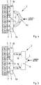
- Fig. 1 an air suction system 3 designed according to the invention is shown, in which charge air is conveyed into a distributor pipe 4 through an air duct 5.
- Gutsaugstrom 3 is designed for an internal combustion engine 1 with two rows of cylinders such that an intake manifold or plenum 6 is provided for each row of cylinders. The air supply takes place in the middle of the manifold 4.
- a throttle body not shown flanged.
- There are provided at each plenum 6 three intake manifolds 7 per row of cylinders, via which the charge air can be supplied to the inlet channel, not shown in the cylinder head and then the combustion chamber. Both plenums 6 are connected to a central distribution pipe 4.
- the respective plenum 6 is integrally formed with the suction tubes 7.
- a distributor tube 4 is arranged between the two plenums 6, which in the present embodiment is formed from a distributor module 4a and from two tube sections 4b, which are formed integrally with the respective plenum.
- the connection can be made by means of band clamps or with a bayonet-like closure.
- a distributor tube length L V is dimensioned as a function of an equivalent distributor tube diameter D V in such a way that a reduction of the charge pressure of the combustion air within the air suction system 3 takes place through a targeted expansion, the expansion taking place partly in the plenum and / or inside the distributor tube.
- the expansion takes place in a region between an entry of the combustion air into the distributor pipe 4, for example from the distributor module 4a, and an exit from the suction pipe 7.
- oscillation occurs within the air suction system, wherein the expansion of the charge air relative to the respective combustion chamber can be achieved continuously within the air suction system, but not necessarily uniformly. This allows the charge air temperature when entering the combustion chamber and thus the fuel / air mixture temperature in the combustion chamber be lowered, so that the engine power can be increased while lowering the specific fuel consumption.
- the oscillating air in the air intake system 3 is sucked during the cooler expansion phase for the mixture preparation, whereby the temperature of the fuel / air mixture is reduced in the combustion chamber.
- the present invention is characterized in that the expansion suction system 3 described here is well suited for internal combustion engines 1 with six or four cylinders.
- the manifold tube length Lv shall be determined by the following formula: 200 - 4 / 3 * L S + 1.7 * n N - 2.22 * D V - 30 ⁇ L v ⁇ 7.2 * 10 6 / n N - 1.5 * L S
- the range for the manifold tube length Lv in which the expansion aspirator can achieve beneficial results is determined by the formula: 34 * D V - 650 - 4 / 3 * L S ⁇ L V
- Ls corresponds to a suction pipe length between the plenum 6 and the cylinder head, not shown.
- the value L V stands for the manifold tube length, which is to be determined differently depending on the embodiment.
- L V is the tube length of the connecting tube between the first and second plenums 6.
- n N corresponds to a rated engine speed at which maximum power is achieved.
- V V ⁇ A V x dx .
- a M V V / L V
- the distribution pipe length L V must be set equal to the distance between the two plenums 6.
- the distributor tube length L V is composed of the lengths of the two sections L V1 and L V2 , wherein in the third embodiment according to Fig. 4 the distributor tube length corresponds to the arc length of the distributor tube 4.
- the distributor tube length L V is composed of the two section lengths L V1 and L V2 .
- the fifth embodiment is according to Fig. 6 to set the manifold tube length L v equal to the distance between the two Plenen 6, wherein in the sixth embodiment according to Fig. 7 the distributor tube length corresponds to the arc length of the distributor tube 4.
- the suction tubes 7 have a length L S , which is below 200 or 150 mm, preferably between 110 and 140 mm.
- the design of the distributor tube length L V as a function of the equivalent distributor tube diameter D V is to be selected such that a ratio of equivalent distributor tube diameter D V to distributor tube length L V is in a range of 0.05 to 0.14, in particular in a range of 0 , 06 to 0.13.
- the internal combustion engine 1 described here operates on the four-stroke principle, wherein the present invention is also suitable for two-stroke internal combustion engines.
- the longitudinal movement of the piston extends between a top dead center OT and a bottom dead center UT.
- combustion air is supplied to the combustion chamber through an inlet channel or a suction pipe 7, wherein the piston moves in a downward movement from a charge exchange dead center LW-TDC to a lower charge exchange dead center UT.
- the piston moves in an upward movement up to an upper ignition dead center ZOT, around which the ignition is made.
- the piston expands in a downward movement to a bottom dead center, wherein in a last cycle of the piston in an upward movement up to an upper charge exchange dead center LW-OT expels the gases from the combustion chamber.
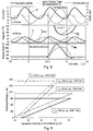
- the dimensions of the opposed Lucassauganlagen according Fig. 8 were chosen to better illustrate the characteristic features so that the typical differences stand out particularly clearly.
- the selected diameter of the resonance tube of the used for comparison resonance suction is 120 mm, the tube length was tuned for 6000 1 / min.
- the suction tank or Plenen 6 correspond to those of a sports car with six cylinders.
- the suction tubes were assumed to be the same and extremely short with 50 mm length in all three examples.
- Fig. 8 In the upper diagram in Fig. 8 are the pressure gradients in plenum 6 after Fig. 13 to 16 shown.
- the constant pressure in the tank marks the boost pressure.
- the charge pressure P that is to say the time-averaged value, is lower by approximately 0.25 bar, because the resonance charge is added for charging by the compressor.
- the boost pressure P is about 0.25 bar above that of the calming tank system and 0.5 bar above that of the resonance system.
- the pressure amplitudes are significantly higher than known from naturally aspirated engines, since due to the higher density of the charge air correspondingly more mass oscillates between the plumes 6.
- Fig. 8 The phase angles of the pressure oscillation differ by approx. 70 ° crank angle. Nevertheless, up to 90 ° phase difference is possible due to other geometries. Due to the phase position of the pressure P, different mass flow characteristics are established at the inlet. For example, if you compare that Mass flow curve with the temperature profile in plenary 6 of the cylinder bank row 1-2-3 according to Fig. 8 respectively. Fig. 13 to 16 , it can be seen that in the Expansionssaugstrom during 120 degrees crank angle of 90 degrees after the upper charge cycle dead center LW-TDC to 20 degrees after the lower charge exchange dead center UT, the temperature in plenum 6 below its average T medium decreases.
- a maximum valve lift at the inlet in a second half of the intake stroke is set, ie, between the upper charge cycle dead center LW-OT and the bottom dead center UT.
- the present invention is characterized in that the air suction system 3 according to the invention is designed such that at the time of combustion air intake within the air suction system 3, in particular in plenum 6 and in the suction pipes 2, a gas-dynamic expansion prevails. As a result, the combustion air substantially at a low temperature T min when the combustion air flows into the combustion chamber.
- a second embodiment is shown, in which in the middle of the manifold 4 instead of the distributor module 4a, a container 4c is provided.
- the manifold tube length L V is set from the distances together, which lie between the respective plenum 6 and the container 4c.
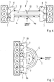
- the internal combustion engine 1 according to the invention also has six cylinders, which are arranged in series.
- the air suction system 3 is designed such that the combustion air is split such that a first plenum 6a is provided for the three front cylinders 2a, wherein a second plenum 6b is provided for the remaining three cylinders 2b.
- the manifold 4 is arcuate, wherein the manifold tube length LV corresponds to the arc length.
- the manifold 4 may be formed in any conceivable shape, for example, arcuate, straight or square or as a combination of different shapes, depending on the cylinder arrangement and motor construction within the scope of the invention.
- FIG Fig. 5 A modified form of the third embodiment is shown in FIG Fig. 5 according to a fourth embodiment, in which case the distributor tube 4 is divided into two sections, wherein a container 11 is positioned between the air guide channel 5 and the respective distributor tube sections 10.
- the manifold pipe length L V is composed of the two manifold pipe section lengths L V1 and L V2 .
- a fifth embodiment of the invention according to Fig. 6 is an additional manifold 12 is disposed between the plenums 6, which can be switched by a switching element, designed here as a flap 13, depending on the engine parameters.
- a switching element designed here as a flap 13
- the size of the equivalent distributor diameter D V is adjustable. Thereby, the achievable expansion of the charge air as a function of the speed of the internal combustion engine 1 can be adjusted.
- the arrangement of an additional manifold 12 with a switching flap 13 is also conceivable in all previously described embodiments.
- one or two additional distributor tubes 12 are to be positioned at the corresponding points for setting the size of the equivalent distributor diameter D V.
- Illustrated sixth embodiment illustrates a modified form of the fifth embodiment Fig. 4 represents.
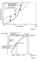
- Fig. 12 are exemplary curves of the charge temperature T B in the combustion chamber after the end of the inflow of the expanded charge air is shown in the combustion chamber.
- Fig. 12 are different temperature values as a function of the speed of the internal combustion engine 1 shown.
- a certain equivalent distributor diameter D V can be set by the additional switchable distributor tube 12 and thus a coordinated expansion of the charge air can be achieved. Accordingly, the setting of a lowest temperature of the charge air at the time of entry into the combustion chamber in dependence on the operating parameters is made possible, so that an optimal efficiency at the respective operating point of the internal combustion engine 1 is present.
- the geometric design of the air intake system 3 leads to such a charge-air expansion that the expansion phase of the charge-air oscillation in the second half of the second intake according to Fig. 8 , upper diagram, lies.
- the second half of the intake come according to Fig. 8
- the lowest temperature values of the charge air are achieved.
- Due to the relatively cold aspirated air masses then results according to the invention a combustion chamber cylinder filling with a relatively lower temperature. This effect causes a shift of the knock limit toward early according to Fig. 11 so that a previous ignition is possible.
- the engine output can be increased by setting the ignition timing of the engine 1 earlier than in warmer cylinder charge. This leads to a significant performance gain. It is conceivable by the lower knock tendency achieved an increase in the compression ratio of the internal combustion engine.
- the compressor 8 sets an adjusted charge pressure which is higher than in the case of conventional supercharged internal combustion engines.
- By such a boost pressure increase results in a charge air temperature increase by about 10 degrees before the charge air cooler 9, wherein after the charge air cooler 9, a charge air temperature increase of about 2 to 3 degrees is measured.
- the set expansion causes a further reduction of the charge air temperature, so that at the inlet of the combustion chamber while maintaining the desired boost pressure level, a low charge air temperature than the usual temperatures Fig. 8 and 10 is present. Therefore, the higher air flow rate is maintained in the combustion chamber and at the same time an increase in performance by the displacement of the knock limit of the internal combustion engine 1 according to 10 and 11 achieved.
- the present invention will be explained in detail with reference to the air intake system 3 for a six-cylinder engine with two cylinder banks.
- the manifold 4 of the air suction system 3 is longer and smaller in diameter, the individual suction tubes 7 are formed shorter.
- the air intake system of the invention reverses the resonance charging effect at higher engine speeds, so that expansion is utilized instead of compression.
- expansion is utilized instead of compression.
- the air is expanded.
- the air is cooled, so that a lower temperature of the fuel-air mixture in the combustion chamber is achieved. This makes it possible to ignite the cooler fuel-air mixture optimized performance.
- the charge pressure ie the value determined over time
- the boost pressure is approximately 0.25 bar above that of the contact container system and 0.5 bar above that of the resonance system.
- the pressure amplitudes are significantly higher than those of the naturally aspirated engines, since the higher density of the charge air causes correspondingly more mass to oscillate between the plenums 6.
- the phase angles of the pressure oscillations differ by approx. 70 ° crank angle. Due to the phase position of the pressure, different mass flow curves at the inlet in accordance with the lower diagram in Fig. 8 on.
- Fig. 13 to 16 is the spatial waveform, as occurs in the air intake system 3 according to the invention, shown.
- the mass flow in the manifold and in the respective intake manifolds of a cylinder bank is shown.
- the air mass within the air intake system 3 oscillates around the manifold center due to the staggered opening and closing of the intake valves. Accordingly, the air mass oscillates between the two plumes 6 and around the manifold center.
- the different path positions at the right end of the Fig. 13 to 16 arise from the different run lengths through the plenum 6 of the cylinder bank, here the cylinders 1, 2 and 3.
- the cylinder bank 1-2-3 in the Fig. 13 to 16 shown on the right.
- Fig. 13 the charge air flows everywhere in the direction of the cylinder bank 1-2-3, the figure in Fig. 13 represents a momentary recording, which corresponds to a time shortly before the charge cycle dead center LW-OT.
- the representation in Fig. 14 is also a snapshot compared to the Fig. 13 a piston position corresponds to the 60 ° crank angle later than the off Fig. 13 ,
- Fig. 15 also shown an instantaneous view, which corresponds to a time at which the piston is between the charge cycle and the bottom dead center.
- this illustration according to Fig. 15 is the air intake process for the cylinder No. 1 shown, in which case the air intake between the time of maximum piston speed and shortly before reaching a maximum intake valve.
- the charge air oscillates in the intake system in the direction of the opposite cylinder bank to cylinder No. 6.
- the internal combustion engine shown here is a firing order 1, 6, 2, 4, 3 and 5 before. Accordingly, the air is drawn to the right in the suction pipe 7 of the cylinder No. 1, so that the charge air expands in the plenum 6.
- FIG. 4 shows four time recordings within one cycle of the charge air oscillation with a 240 ° crank angle oscillation period. This results from the fact that the present internal combustion engine passes through three cycles per four-stroke cycle within 720 ° crank angle.
- the air intake system 3 according to the invention achieves a significant lowering of the temperature of the charge air below the average value T Mittel .
Landscapes
- Engineering & Computer Science (AREA)
- Chemical & Material Sciences (AREA)
- Combustion & Propulsion (AREA)
- Mechanical Engineering (AREA)
- General Engineering & Computer Science (AREA)
- Characterised By The Charging Evacuation (AREA)
- Supercharger (AREA)
Description
Die Erfindung betrifft eine Brennkraftmaschine, insbesondere eine fremdgezündete Brennkraftmaschine, mit einem Verdichter gemäß dem Oberbegriff des Anspruchs 1.The invention relates to an internal combustion engine, in particular a spark-ignition internal combustion engine, with a compressor according to the preamble of
Beim Betrieb von Brennkraftmaschinen werden üblicherweise Luftsauganlagen verwendet, welche eine Schwing- oder Resonanzrohraufladung oder eine Kombination dieser beiden Aufladungen erzielen. Bei einer aufgeladenen Brennkraftmaschine ergibt sich infolge der Verdichtung der angesaugten Verbrennungsluft eine Anhebung der Lufttemperatur. Der für Saugmotoren begehrte Aufladeeffekt durch Schwingrohraufladung oder Resonanzaufladung ist, insbesondere bei aufgeladenen Ottomotoren, unerwünscht, da durch die gasdynamische Kompression die Ladeluft erwärmt wird und dadurch die Neigung zu klopfender Verbrennung zunimmt. Ein Beispiel eines solchen Systems ist in der
Zur Vermeidung einer weiteren Aufladung wird daher bei aufgeladenen Diesel- und Ottomotoren hinter dem Verdichter ein Ladeluftkühler zur Kühlung der Ladeluft positioniert. Hierdurch soll, insbesondere bei aufgeladenen Ottomotoren, die Gefahr eines klopfenden Motors minimiert werden. Eine weitere Reduzierung der Ladelufttemperatur ist durch einen vergrößerten Ladeluftkühler in der Regel aus baulichen Gründen nicht möglich. Demzufolge werden zur Erhöhung des Wirkungsgrades des Ladeluftkühlers stromab von diesem Entspannungseinrichtungen vorgesehen, um eine Verbrennungslufttemperatur weiter zu reduzieren. Aus der
Aus der
Der Erfindung liegt daher die Aufgabe zugrunde, eine aufgeladene Brennkraftmaschine bereitzustellen, bei der eine optimierte Luftansaugung erzielt werden kann. Diese wird erfindungsgemäß durch eine Vorrichtung mit den Merkmalen des Anspruchs 1 gelöst.The invention is therefore based on the object to provide a supercharged internal combustion engine, in which an optimized air intake can be achieved. This is achieved by a device having the features of
Die erfindungsgemäße Brennkraftmaschine zeichnet sich dadurch aus, dass die Luftsauganlage derart ausgebildet ist, dass die Luftansaugung in den Brennraum während einer Expansionsphase der Luftmasse in der Luftsauganlage stattfindet. Demnach strömt mindestens ein Teil der Luftmasse in den Brennraum während der Expansionsphase ein. Dabei findet die Ladeluftexpansion teilweise im Plenum, im jeweiligen Saugrohr und/oder innerhalb des Verteilerrohres statt. Erfindungsgemäß ist eine kontinuierliche, aber nicht zwingend gleichmäßige, Expansion zwischen dem Eintritt der Verbrennungsluft in das Verteilerrohr bis zum Einströmen der Verbrennungsluft in den Brennraum, d.h., bis zum Austritt aus dem Saugrohr, erzielbar.The internal combustion engine according to the invention is characterized in that the air suction system is designed such that the air intake takes place in the combustion chamber during an expansion phase of the air mass in the air suction. Accordingly, at least part of the air mass flows into the combustion chamber during the expansion phase. The charge air expansion takes place partly in the plenum, in the respective intake manifold and / or within the distributor tube. According to the invention, a continuous, but not necessarily uniform, expansion between the entry of the combustion air into the manifold until the combustion air flows into the combustion chamber, that is, until it exits the intake manifold, is achievable.
Erfindungsgemäß weist die Luftsauganlage eine derartige Verteilerrohrlänge auf, dass die Luftansaugung in den Brennraum der Brennkraftmaschine während einer Expansionsphase der Luftmasse in der Luftsauganlage stattfindet. Vorzugsweise ist die Verteilerrohrlänge so bemessen, dass zum Zeitpunkt der Luftansaugung eine Verringerung des Ladedruckes innerhalb der Luftsauganlage erzielbar ist. Mit der erfindungsgemäßen Ausgestaltung der Luftsauganlage, insbesondere der Bemessung der Verteilerrohrlänge, werden Resonanzeffekte bei maximaler Motorleistung vermieden, und zusätzlich ein Luftansaugverfahren ermöglicht, mit dem eine gezielte und auf den Ansaugzeitpunkt abgestimmte Expansion herbeigeführt wird.According to the invention, the air suction system has such a distributor tube length that the air intake into the combustion chamber of the internal combustion engine takes place during an expansion phase of the air mass in the air suction system. Preferably, the manifold tube length is dimensioned so that at the time of air intake, a reduction of the boost pressure within the air suction can be achieved. With the embodiment of the air suction system according to the invention, in particular the dimensioning of the distributor tube length, resonance effects at maximum engine power are avoided, and in addition an air intake method is made possible with which a targeted expansion adapted to the intake time is brought about.
Durch die erfindungsgemäße Ausgestaltung der Luftsauganlage wird ein Verfahren zur Luftansaugung ermöglicht, mit dem zum Zeitpunkt der Luftansaugung die Temperatur der durch den jeweiligen Zylinder angesaugten Luftmasse zwischen dem Plenum und dem Brennraum der Brennkraftmaschine verringert wird. Vorzugsweise erfolgt eine Verringerung der Luftmassentemperatur unterhalb eines Temperaturmittelwertes. Um einen solchen Temperaturmittelwert schwanken die Temperaturwerte der Luftmasse innerhalb der Luftsauganlage. Ein solcher Temperaturmittelwert stellt sich in etwa bei der Verteilerrohrmitte ein.The inventive design of the air intake system, a method for air intake is made possible, with the temperature of the sucked in by the respective cylinder air mass between the plenum and the combustion chamber of the internal combustion engine is reduced at the time of air intake. Preferably, the air mass temperature is reduced below a mean temperature value. The temperature values of the air mass within the air suction system fluctuate around such a mean temperature value. Such a mean temperature is set approximately at the manifold center.
Die erfindungsgemäße Luftsauganlage zeichnet sich dadurch aus, dass die Verteilerrohrlänge in Abhängigkeit von einem äquivalenten Verteilerrohrdurchmesser bemessen ist. Hierdurch wird die schwingende Luft in der Luftsauganlage während der kühleren Expansionsphase in den jeweiligen Brennraum angesaugt, so dass eine relativ niedrige Temperatur des Brennstoff/Luft-Gemisches im Brennraum vorliegt.The air suction system according to the invention is characterized in that the distributor tube length is dimensioned as a function of an equivalent distributor tube diameter. As a result, the oscillating air is sucked in the air suction during the cooler expansion phase in the respective combustion chamber, so that there is a relatively low temperature of the fuel / air mixture in the combustion chamber.
Mit der erfindungsgemäßen Ausgestaltung der Luftsauganlage wird durch die erzielte Expansion eine effektive Kühlung der Ladeluft innerhalb der Luftsauganlage ohne den Einsatz von zusätzlichen beweglichen Bauteilen bewirkt. Dadurch wird eine kostengünstige und effiziente Luftsauganlage für aufgeladene Brennkraftmaschinen zur Verfügung gestellt, wobei sich die erfindungsgemäße Expansionsluftsauganlage sowohl für aufgeladene Otto- als auch für Dieselmotoren eignet.With the inventive design of the air intake system is achieved by the expansion achieved effective cooling of the charge air within the air suction without the use of additional moving components. This provides a cost-effective and efficient air intake system for supercharged internal combustion engines, with the expansion air intake system according to the invention being suitable both for supercharged petrol engines and for diesel engines.
In einer Ausgestaltung der Erfindung ist die Verteilerrohrlänge in Abhängigkeit von einer Nenndrehzahl der Brennkraftmaschine bemessen. Somit wird die vorliegende Luftsauganlage bei aufgeladenen Brennkraftmaschinen optimal eingesetzt und eine gezielte Abstimmung, insbesondere bei Sportfahrzeugen, für höhere Lastpunkte und Drehzahlen ermöglicht.In one embodiment of the invention, the distributor tube length is dimensioned as a function of a rated speed of the internal combustion engine. Thus, the present air intake system is optimally used in supercharged internal combustion engines and allows targeted tuning, especially in sports vehicles, for higher load points and speeds.
Mit der erfindungsgemäßen Luftsauganlage sinkt die Temperatur der angesaugten Luftmasse im Plenum unter dem Mittelwert während eines Kurbelwinkelbereiches zwischen 90° nach dem oberen Ladungswechsel-Totpunkt und 20° nach dem unteren Ladungswechsel-Totpunkt. Hierdurch können mehr als 20° Temperaturabsenkung erzielt werden. Folglich wird eine deutliche Verschiebung des Zündwinkels nach früh ermöglicht, so dass sich der Wirkungsgrad der Brennkraftmaschine verbessert. Durch den früheren Zündzeitpunkt sinkt die Abgastemperatur, so dass ein Anfettungsbedarf zum Schutz der Abgasturbine geringer wird. Als eine weitere Folge der Wirkungsgradverbesserung wird für die gleiche Motorleistung weniger Ladeluft und Kraftstoff benötigt, wodurch der gesamte Aufladeprozess der Brennkraftmaschine optimiert wird.With the air suction system according to the invention, the temperature of the aspirated air mass decreases in plenum below the mean value during a crank angle range between 90 ° after the upper charge exchange dead center and 20 ° after the lower charge exchange dead center. As a result, more than 20 ° temperature reduction can be achieved. Consequently, a significant shift of the ignition angle is made possible early, so that the efficiency of the internal combustion engine improves. Due to the earlier ignition, the exhaust gas temperature drops, so that a Anfettungsbedarf to protect the exhaust gas turbine is lower. As a further consequence of the efficiency improvement, less charge air and fuel is needed for the same engine performance, thereby optimizing the overall engine boost process.
Nach einem weiteren Aspekt der der Erfindung erfolgt die Ausbildung der Verteilerrohrlänge in Abhängigkeit von dem äquivalenten Verteilerrohrdurchmesser derart, dass ein Verhältnis von äquivalentem Verteilerrohrdurchmesser zu Verteilerrohrlänge von 0,05 bis 0,14 vorliegt. Dabei sollte die Saugrohrlänge nicht mehr als 200 mm oder 150 mm, insbesondere bei einer Nenndrehzahl zwischen 5500 und 7000 Umdrehungen pro Minute, bemessen sein. Vorzugesweise beträgt dabei das Verhältnis von äquivalentem Verteilerrohrdurchmesser zu Verteilerrohrlänge 0,066, 0,114 oder 0,136. Hierdurch kommt innerhalb der Luftsauganlage eine optimierte Expansion der verdichteten Verbrennungsluft zustande, so dass die Verbrennungsluft aus der Luftsauganlage mit einer deutlich niedrigeren Temperatur in den Einlasskanal im Zylinderkopf einströmt.According to a further aspect of the invention, the formation of the manifold tube length is dependent on the equivalent manifold diameter such that there is a ratio of equivalent manifold diameter to manifold length of 0.05 to 0.14. The suction tube length should not be more than 200 mm or 150 mm, especially at a rated speed between 5500 and 7000 revolutions per minute. In this case, the ratio of equivalent distributor tube diameter to distributor tube length is preferably 0.066, 0.114 or 0.136. This results in an optimized expansion of the compressed combustion air within the air suction, so that the combustion air flows from the air intake with a significantly lower temperature in the inlet channel in the cylinder head.
Durch die neuartige geometrische Bestimmung des Verteilerrohrs der Luftsauganlage liegt im Vergleich zu den üblichen Sauganlagen ein Verteilerrohr mit einem kleinen Durchmesser vor, so dass der bauliche Aufwand im Motorraum optimiert wird. Die erfindungsgemäße Luftsauganlage kehrt durch die erfindungsgemäße Bemessung den bekannten Resonanzaufladeeffekt, insbesondere bei hohen Motordrehzahlen, komplett um. Anstelle einer Kompression wird eine Expansion der Verbrennungsluft erzielt und diese weiter abgekühlt. Somit liegt eine niedrigere Temperatur des Brennstoff/Luft-Gemisches im Brennraum vor, so dass der Zündzeitpunkt der Brennkraftmaschine leistungsoptimal einstellbar ist.Due to the novel geometric determination of the distributor tube of the air suction system is compared to the usual suction systems before a manifold with a small diameter, so that the structural complexity in the engine compartment is optimized. The air intake according to the invention returns by the inventive design the known resonance charging effect, especially at high engine speeds, completely. Instead of compression, an expansion of the combustion air is achieved and this cooled further. Thus, there is a lower temperature of the fuel / air mixture in the combustion chamber, so that the ignition timing of the internal combustion engine is adjustable in performance.
In einer weiteren Ausgestaltung der Erfindung weist die Brennkraftmaschine eine oder zwei Zylinderreihen auf, wobei die Anzahl der Zylinder insgesamt sechs beträgt. Gemäß der Erfindung hat sich bei einer fremdgezündeten 6-Zylinder-Brennkraftmaschine der Boxerbauart gezeigt, dass die vorliegende Luftsauganlage zu einer deutlichen Wirkungsgradverbesserung führt. Dennoch eignet sich die vorliegende Luftsauganlage ebenfalls für Brennkraftmaschinen mit vier Zylindern.In a further embodiment of the invention, the internal combustion engine has one or two rows of cylinders, wherein the number of cylinders is six in total. According to the invention, it has been shown in a spark-ignition 6-cylinder internal combustion engine of the boxer type that the present air suction system leads to a significant improvement in efficiency. Nevertheless, the present air suction system is also suitable for internal combustion engines with four cylinders.
In einer Ausgestaltung der Erfindung sieht die vorliegende Erfindung zur weiteren Verbesserung der Zylinderfüllung, insbesondere bei aufgeladenen fremdgezündeten Brennkraftmaschinen, eine zusätzliche Erhöhung des Ladedruckes durch den Verdichter vor, um den verminderten Ladedruckbetrag durch die innerhalb der Luftsauganlage erzielte Expansion auszugleichen. Vorzugsweise wird bei gleicher Motorleistung ein höher Ladedruck um 3 bis 10 % als die üblichen Ladedrücke eingestellt. Dabei liegen die üblichen Ladedrücke zwischen 0,9 bar und 1,5 bar.In one embodiment of the invention, to further improve the cylinder filling, especially in supercharged spark-ignition internal combustion engines, the present invention provides an additional increase in the boost pressure through the compressor to compensate for the reduced boost pressure by the expansion achieved within the air suction system. Preferably, with the same engine power, a higher charge pressure is set by 3 to 10% than the usual charge pressures. The usual charge pressures are between 0.9 bar and 1.5 bar.
Durch einen höher eingestellten Ladedruck steigt nach dem Verdichter die Verbrennungslufttemperatur an, so dass durch das höher eingestellte Temperaturniveau der Verbrennungsluft im Ladeluftkühler eine größere Wärmemenge abgeführt wird. Gemäß der Erfindung liegt eine höhere Temperaturdifferenz über den Ladeluftkühler um etwa 3 bis 10 % als bei üblichen Ladedrücken vor. Dadurch kommt nach dem Ladeluftkühler eine Verbrennungslufttemperatur zustande, die nur geringfügig höher liegt als die mit einer üblichen bzw. konventionellen Aufladung, da die abgeführte Wärmemenge am Ladeluftkühler bis zu 55 % höher liegt als bei üblichen Ladedruckverhältnissen. Der hier durch den Einsatz der erfindungsgemäßen Luftsauganlage zusätzlich erzielte thermische Gewinn führt zu einer niedrigeren Temperatur des Brennstoff/Luft-Gemisches im Brennraum, da sowohl das Druck- als auch das Temperaturniveau im Brennraum zum Einlassventilschließzeitpunkt zwischen 3 und 4 % niedriger liegt als bei üblichen Luftsauganlagen. Folglich kann bei einem Sportfahrzeug mit einem aufgeladenen Motor, insbesondere bei hohen Lastpunkten und Drehzahlen, bei gleicher Motorleistung ein günstiger Kraftstoffverbrauch oder eine höhere Motorleistung beim gleichen Kraftstoffverbrauch erzielt werden.By a higher set boost pressure rises after the compressor, the combustion air temperature, so that a larger amount of heat is dissipated by the higher set temperature level of the combustion air in the intercooler. According to the invention, a higher temperature difference across the charge air cooler by about 3 to 10% than in conventional charging pressures before. This results in a combustion air temperature after the intercooler, which is only slightly higher than that with a conventional or conventional charging, since the dissipated amount of heat at the intercooler is up to 55% higher than in conventional boost pressure conditions. The additional thermal gain achieved here through the use of the air suction system according to the invention leads to a lower temperature of the fuel / air mixture in the combustion chamber, since both the pressure and the temperature level in the combustion chamber at the intake valve closing time point between 3 and 4% lower than conventional air suction systems. Consequently, in a sports car with a supercharged engine, especially at high load points and speeds, with the same engine power, a favorable fuel consumption or a higher engine output can be achieved with the same fuel consumption.
In einer weiteren vorteilhaften Ausgestaltung der Erfindung erfolgt bei der erfindungsgemäßen Brennkraftmaschine durch den Einsatz eines Abgasturboladers mit einer verstellbaren Turbinengeometrie in Verbindung mit der erfindungsgemäßen Expansionsluftsauganlage eine ständige Anpassung der erzielten Expansion der Verbrennungsluft innerhalb der Luftsauganlage an den Betriebszustand des Motors. Hierdurch kann bei der erfindungsgemäßen Brennkraftmaschine eine Optimierung des Zündzeitpunktes und daher eine weitere Wirkungsgradverbesserung erreicht werden.In a further advantageous embodiment of the invention takes place in the internal combustion engine according to the invention by the use of an exhaust gas turbocharger with an adjustable turbine geometry in conjunction with the expansion air intake according to the invention a constant adjustment of the achieved expansion of the combustion air within the air intake to the operating condition of the engine. As a result, in the internal combustion engine according to the invention an optimization of the ignition timing and therefore a further improvement in efficiency can be achieved.
Weitere Merkmale und Merkmalkombinationen ergeben sich aus der Beschreibung. Konkrete Ausführungsbeispiele der Erfindung sind in den Zeichnungen vereinfacht dargestellt und in der nachfolgenden Beschreibung näher erläutert. Dabei zeigen:
- Fig. 1
- eine Abbildung einer erfindungsgemäßen Luftsauganlage einer aufgeladenen Brennkraftmaschine mit in zwei Reihen angeordneten Zylindern,
- Fig. 2
- eine schematische Darstellung der Luftsauganlage nach
Fig. 1 gemäß einem ersten Ausführungsbeispiel, - Fig. 3
- eine schematische Darstellung der Luftsauganlage nach
Fig. 1 gemäß einem zweiten Ausführungsbeispiel, - Fig. 4
- eine schematische Darstellung einer erfindungsgemäßen Luftsauganlage einer Brennkraftmaschine mit in einer Reihe angeordneten Zylindern gemäß einem dritten Ausführungsbeispiel ,
- Fig. 5
- eine schematische Darstellung der Luftsauganlage nach
Fig. 4 gemäß einem vierten Ausführungsbeispiel, - Fig. 6
- eine schematische Darstellung der Luftsauganlage nach
Fig. 1 gemäß einem fünften Ausführungsbeispiel, - Fig. 7
- eine schematische Darstellung der Luftsauganlage nach
Fig. 4 gemäß einem sechsten Ausführungsbeispiel, - Fig. 8
- ein schematisches Diagramm vom Druck-, Temperatur- und Massenstromverlauf innerhalb der Luftsauganlage der erfindungsgemäßen Brennkraftmaschine,
- Fig. 9
- ein schematische Abbildung der Abmessungsverhältnisse der Luftsauganlage der erfindungsgemäßen Brennkraftmaschine,
- Fig. 10
- ein schematische Darstellung der Ladungstemperatur im Brennraum einer Brennkraftmaschine,
- Fig. 11
- eine schematische Darstellung der Auswirkung der Luftsauganlage nach
Fig. 1 auf die Motorleistung einer Brennkraftmaschine, - Fig. 12
- eine schematische Darstellung der Temperaturwerte der Zylinderladung im Brennraum einer erfindungsgemäßen Brennkraftmaschine zum Zeitpunkt "Einlassventil-Schließt" in Abhängigkeit von der eingestellten Drehzahl,
- Fig. 13
- einen Massenstrom- und Temperaturverlauf im Verteilerrohr der Luftsauganlage nach
Fig. 1 zu einem Zeitpunkt vor dem Ladungswechsel-Totpunkt, - Fig. 14
- einen Massenstrom- und Temperaturverlauf im Verteilerrohr der Luftsauganlage nach
Fig. 1 zu einem Zeitpunkt nach dem Ladungswechsel-Totpunkt, - Fig. 15
- einen Massenstrom- und Temperaturverlauf im Verteilerrohr der Luftsauganlage nach
Fig. 1 zu einem Zeitpunkt zwischen Ladungswechsel-Totpunkt und dem unteren Totpunkt und - Fig. 16
- einen Massenstrom- und Temperaturverlauf im Verteilerrohr der Luftsauganlage nach
Fig. 1 beim unteren Totpunkt.
- Fig. 1
- 1 shows an illustration of an air intake system according to the invention of a supercharged internal combustion engine with cylinders arranged in two rows,
- Fig. 2
- a schematic representation of the air intake after
Fig. 1 according to a first embodiment, - Fig. 3
- a schematic representation of the air intake after
Fig. 1 according to a second embodiment, - Fig. 4
- 1 is a schematic representation of an air suction system according to the invention of an internal combustion engine with cylinders arranged in a row according to a third exemplary embodiment,
- Fig. 5
- a schematic representation of the air intake after
Fig. 4 according to a fourth embodiment, - Fig. 6
- a schematic representation of the air intake after
Fig. 1 according to a fifth embodiment, - Fig. 7
- a schematic representation of the air intake after
Fig. 4 according to a sixth embodiment, - Fig. 8
- a schematic diagram of the pressure, temperature and mass flow curve within the Luftsauganlage the internal combustion engine according to the invention,
- Fig. 9
- a schematic illustration of the dimensional ratios of the air suction system of the internal combustion engine according to the invention,
- Fig. 10
- a schematic representation of the charge temperature in the combustion chamber of an internal combustion engine,
- Fig. 11
- a schematic representation of the effect of the air suction after
Fig. 1 on the engine power of an internal combustion engine, - Fig. 12
- a schematic representation of the temperature values of the cylinder charge in the combustion chamber of an internal combustion engine according to the invention at the time "intake valve closes" in dependence on the set speed,
- Fig. 13
- a mass flow and temperature profile in the manifold of the air intake after
Fig. 1 at a time prior to the charge cycle dead center, - Fig. 14
- a mass flow and temperature profile in the manifold of the air intake after
Fig. 1 at a time after the charge cycle dead center, - Fig. 15
- a mass flow and temperature profile in the manifold of the air intake after
Fig. 1 at a time between charge cycle dead center and bottom dead center and - Fig. 16
- a mass flow and temperature profile in the manifold of the air intake after
Fig. 1 at bottom dead center.
Eine Brennkraftmaschine 1 mit Aufladung weist mindestens einen Zylinder 2 auf, in dem ein nicht dargestellter Brennraum zwischen einem im Zylinder 2 längsverschieblich gehaltenen Kolben und einem Zylinderkopf gebildet ist. Die Brennkraftmaschine 1 saugt Verbrennungsluft durch einen Verdichter 8 an. Die Aufladung der Brennkraftmaschine 1 kann im Sinne der Erfindung durch einen Verdichter 8 zustande kommen, der als Bestandteil eines Abgasturboladers, eines mechanischen Kompressors oder eines elektrischen Kompressors ausgebildet ist. Durch die Kompression der Verbrennungsluft steigt die Ladelufttemperatur an. Um diese zu reduzieren, ist dem Verdichter 8 ein Ladeluftkühler 9 nachgeschaltet.An
In
Erfindungsgemäß ist eine Verteilerrohrlänge LV in Abhängigkeit von einem äquivalenten Verteilerrohrdurchmesser DV derart bemessen, dass eine Verringerung des Ladedruckes der Verbrennungsluft innerhalb der Luftsauganlage 3 durch eine gezielte Expansion erfolgt, wobei die Expansion teilweise im Plenum und/oder innerhalb des Verteilerrohres stattfindet. Erfindungsgemäß findet die Expansion in einem Bereich zwischen einem Eintritt der Verbrennungsluft in das Verteilerrohr 4, z.B. ab dem Verteilermodul 4a, und einem Austritt aus dem Saugrohr 7 statt. Je nach Zündfolge der jeweiligen Zylinder 2 tritt innerhalb der Luftsauganlage eine Schwingung auf, wobei die Expansion der Ladeluft auf den jeweiligen Brennraum bezogen kontinuierlich innerhalb der Luftsauganlage, aber nicht zwingend gleichmäßig, erzielbar ist. Dadurch kann die Ladelufttemperatur beim Eintritt in den Brennraum und somit die Brennstoff/Luft-Gemischtemperatur im Brennraum abgesenkt werden, so dass die Motorleistung bei gleichzeitiger Absenkung des spezifischen Kraftstoffverbrauches gesteigert werden kann.According to the invention, a distributor tube length L V is dimensioned as a function of an equivalent distributor tube diameter D V in such a way that a reduction of the charge pressure of the combustion air within the
Gemäß der vorliegenden Erfindung wird die schwingende Luft in der Luftsauganlage 3 während der kühleren Expansionsphase für die Gemischaufbereitung angesaugt, wodurch die Temperatur des Brennstoff/Luft-Gemisches im Brennraum reduziert wird. Das führt zu einer deutlichen Steigerung der Effizienz. Beispielsweise wird bei maximaler Leistung eines Sechs-Zylinder-Boxermotors eine Verringerung des Kraftstoffverbrauchs um etwa 15 % erreicht.According to the present invention, the oscillating air in the
Die vorliegende Erfindung zeichnet sich dadurch aus, dass die hier beschriebene Expansionssauganlage 3 sich für Brennkraftmaschinen 1 mit sechs oder vier Zylindern gut eignet. Für einen aufgeladenen Sechs-Zylinder-Motor ist die Verteilerrohrlänge Lv durch folgende Formel zu bestimmen: ![]()
![]()
Bei einem aufgeladenen Vier-Zylinder-Motor ist der Bereich für die Verteilerrohrlänge Lv, in dem die Expansionssauganlage vorteilhafte Ergebnisse erzielen kann, durch folgende Formel bestimmt: ![]()
![]()
Dabei entspricht Ls einer Saugrohrlänge zwischen dem Plenum 6 und dem nicht dargestellten Zylinderkopf. Der Wert LV steht für die Verteilerrohrlänge, wobei diese sich je nach Ausführungsbeispiel unterschiedlich zu bestimmen ist. LV ist die Rohrlänge des Verbindungsrohres zwischen dem ersten und dem zweiten Plenum 6. Bei den Ausführungsbeispielen mit dem Behälter 4c bzw. 11 gemäß
Bei einem Verteilerrohr 4 mit veränderlicher Querschnittsfläche AV(x) ist das Innenvolumen VV des Verbindungsrohres durch folgende Formel zu bestimmen: ![]()
![]()
Dabei ist x die Wegkoordinate entlang einer Rohrmittellinie. Bereiche, in denen AV(x) größer ist als die doppelte mittlere Querschnittsfläche AM werden nicht als Rohr, sondern als Behälter gewertet und gehen nicht in die Berechnungen der Rohrlänge LV und des äquivalenten Verbindungsrohrdurchmessers DV ein.Where x is the path coordinate along a pipe centerline. Areas where A V (x) is greater than twice the average cross-sectional area A M are not considered as a pipe but as a container and are not included in the calculations of the pipe length L V and the equivalent pipe diameter D V.
Daraus ergibt sich der äquivalente Verbindungsrohrdurchmesser DV nach der Formel: ![]()
![]()
Bei dem ersten Ausführungsbeispiel gemäß
Gemäß der Erfindung ergeben sich bei einer Auslegung der Expansionssauganlage 3 in Anlehnung an die obigen Formel vorteilhafte niedrige Temperaturen an der Einlassöffnung des Brennraumes. Insbesondere bei einer Verteilerrohrlänge von etwa 440 mm und einem äquivalenten Verteilerrohrdurchmesser DV von 50 oder 60 mm bzw. zwischen 50 und 60 mm sind hohe Expansionsgrade einstellbar. Dabei weisen die Saugrohre 7 eine Länge LS auf, die unterhalb 200 oder 150 mm liegt, vorzugsweise zwischen 110 und 140 mm. Demnach ist die Ausgestaltung der Verteilerrohrlänge LV in Abhängigkeit vom äquivalenten Verteilerrohrdurchmesser DV so zu wählen, dass sich ein Verhältnis von äquivalentem Verteilerrohrdurchmesser DV zu Verteilerrohrlänge LV in einem Bereich von 0,05 bis 0,14, insbesondere in einem Bereich von 0,06 bis 0,13 ergibt. Es hat sich dabei gezeigt, dass bei einem Sechs-Zylinder-Motor Verhältnisse von 0,066, 0,114 oder 0,136 bzw. Verhältnisse, die zwischen diesen Werten liegen, zu optimalen Ergebnissen im Sinne der vorliegenden Erfindung geführt haben, insbesondere wenn die Saugrohrlänge LS kürzer als 150 mm beträgt.According to the invention, in a design of the
Die hier beschriebene Brennkraftmaschine 1 arbeitet nach dem Vier-Takt-Prinzip, wobei sich die vorliegende Erfindung ebenfalls für Zwei-Takt-Brennkraftmaschinen eignet. Die Längsbewegung des Kolbens erstreckt sich zwischen einem oberen Totpunkt OT und einem unteren Totpunkt UT. Im ersten Ansaugtakt der Vier-Takt-Brennkraftmaschine 1 wird dem Brennraum durch einen Einlasskanal bzw. ein Saugrohr 7 Verbrennungsluft zugeführt, wobei der Kolben sich in einer Abwärtsbewegung von einem Ladungswechsel-Totpunkt LW-OT bis zu einem unteren Ladungswechsel-Totpunkt UT bewegt. In einem nachfolgenden Kompressionstakt bewegt sich der Kolben in einer Aufwärtsbewegung bis zu einem oberen Zünd-Totpunkt ZOT, um den die Zündung vorgenommen wird. Danach expandiert der Kolben in einer Abwärtsbewegung bis zu einem unteren Totpunkt, wobei in einem letzten Takt der Kolben in einer Aufwärtsbewegung bis zu einem oberen Ladungswechsel-Totpunkt LW-OT die Gase aus dem Brennraum ausschiebt.The
Die in
Die Abmessungen der gegenübergestellten Luftsauganlagen gemäß
Im oberen Diagramm in
Gemäß
Das Ergebnis zeigt sich schließlich am Temperaturverlauf TB im Brennraum des ersten Zylinders. Im Vergleich zur Beruhigungsbehälter-Sauganlage, die den idealisierten Stand der Technik darstellen soll, wird eine Temperaturabsenkung um mehr als 20 Grad erzielt. Dieser Effekt ermöglicht gemäß
Wie im oberen Diagramm aus
Gemäß
Eine abgewandelte Form des dritten Ausführungsbeispiels ist in
Nach einem fünften Ausführungsbeispiel der Erfindung gemäß
In
Die erfindungsgemäße Expansionssauganlage 3 und deren Ausgestaltung ist im Folgenden mit weiteren Einzelheiten näher erläutert. Die schematische Darstellung der in
Die geometrische Ausgestaltung der Luftsauganlage 3 führt zu einer derartigen Ladeluftexpansion, dass die Expansionsphase der Ladeluftschwingung in der zweiten Hälfte des zweiten Ansaugvorgangs gemäß
Folglich kann die Motorleistung erhöht werden, indem der Zündzeitpunkt der Brennkraftmaschine 1 früher eingestellt wird als bei einer wärmeren Zylinderfüllung. Dies führt zu einem wesentlichen Leistungsgewinn. Denkbar ist durch die erzielte geringere Klopfneigung eine Anhebung des Verdichtungsverhältnisses der Brennkraftmaschine.Consequently, the engine output can be increased by setting the ignition timing of the
Um die erzielte Expansion in der Luftsauganlage 3 zu kompensieren, wird durch den Verdichter 8 ein angepasster Ladedruck eingestellt, der höher liegt als bei konventionellen aufgeladenen Brennkraftmaschinen. Eine Erhöhung des Ladedruckes mit der vorliegenden Expansionssauganlage 3 kann beispielsweise zwischen 0,15 und 0,3 bar höher als bei konventionellen Sauganlagen betragen. Durch eine solche Ladedruckerhöhung ergibt sich eine Ladelufttemperaturerhöhung um ca. 10 Grad vor dem Ladeluftkühler 9, wobei nach dem Ladeluftkühler 9 eine Ladelufttemperaturerhöhung von etwa 2 bis 3 Grad gemessen wird. Demnach wird durch die eingestellte Expansion eine weitere Reduzierung der Ladelufttemperatur bewirkt, so dass am Einlass des Brennraumes unter Beibehaltung des gewünschten Ladedruckniveaus eine niedrige Ladelufttemperatur als die üblichen Temperaturen gemäß
Die vorliegende Erfindung wird anhand der Luftsauganlage 3 für einen Sechs-Zylinder-Motor mit zwei Zylinderbänken detailliert erläutert. Im Vergleich zu einer klassischen Sauganlage bei einem solchen Motor ist das Verteilerrohr 4 der Luftsauganlage 3 länger und im Durchmesser kleiner, wobei die einzelnen Saugrohre 7 kürzer ausgebildet sind.The present invention will be explained in detail with reference to the
Mit der vorliegenden Erfindung kehrt die erfindungsgemäße Luftsauganlage den Resonanzaufladeeffekt bei höheren Motordrehzahlen um, so dass anstelle einer Kompression eine Expansion genutzt wird. Durch diese Expansion innerhalb der Luftsauganlage 3 wird die Luft ausgedehnt. Dadurch wird die Luft abgekühlt, so dass eine niedrigere Temperatur des Kraftstoff-Luft-Gemisches im Brennraum zustande kommt. Hierdurch lässt sich das kühlere Kraftstoff-Luft-Gemisch leistungsoptimiert zünden.With the present invention, the air intake system of the invention reverses the resonance charging effect at higher engine speeds, so that expansion is utilized instead of compression. By this expansion within the
Gemäß
In den
Darüber hinaus ist in
Claims (17)
- Internal combustion engine (1) having multiple cylinders (2), having an air intake system (3), having a compressor (8) for feeding the combustion air, and having a combustion chamber which is arranged in the cylinder (2) and which is delimited between a piston and a cylinder head, wherein- the air intake system (3) is formed from at least one distributor pipe (4), multiple intake pipes (7) and at least one plenum (6), wherein the plenum (6) is positioned between the distributor pipe (4) and the intake pipes (7), wherein- the combustion air is fed to the air intake system (3) via an air-guiding duct (5) which opens into the distributor pipe (4), and- the charge pressure (p) of the combustion air is reduced between the exit from the compressor (8) and the entry into the combustion chamber of the internal combustion engine (1),characterized in that- the air intake system (3) is designed such that at least one part of the air mass flows into the combustion chamber of the internal combustion engine (1) during an expansion phase of the air mass in the air intake system, wherein it is possible to obtain a continuous, but not imperatively uniform, expansion between the entry of the combustion air into the distributor pipe (4) and the flow of the combustion air into the combustion chamber.
- Internal combustion engine (1) according to Claim 1, characterized in that a distributor pipe length is dimensioned such that, at the time of the intake of air, it is possible to obtain a reduction in the charge pressure (P) within the air intake system (3).
- Internal combustion engine (1) according to Claim 1 or 2, characterized in that, at the time of the intake of air, the temperature of the air mass which is sucked in by the respective cylinder is reduced between the plenum (6) and the combustion chamber of the internal combustion engine (1).
- Internal combustion engine (1) according to Claim 3, characterized in that the reduction in the air mass temperature below the mean temperature value (Tmean) is realized during a crank angle range of between 50° after charge-exchange top dead centre (CE-TDC) and 40° after charge-exchange bottom dead centre (BDC), in particular of between 90° after charge-exchange top dead centre (CE-TDC) and 20° after charge-exchange bottom dead centre (BDC).
- Internal combustion engine (1) according to one of Claims 1 to 4, characterized in that the air intake system (3) is designed such that a distributor pipe length (Lv) is dimensioned as a function of an equivalent distributor pipe diameter (Dv).
- Internal combustion engine (1) according to Claim 5, characterized in that the configuration of the distributor pipe length (Lv) as a function of an equivalent distributor pipe diameter (Dv) is realized such that the ratio of equivalent distributor pipe diameter (Dv) to distributor pipe length (Lv) is 0.05 to 0.14, or 0.06 to 0.13.
- Internal combustion engine (1) according to one of Claims 1 to 6, characterized in that the configuration of the air intake system (3) is realized such that the intake pipe length (Ls) is shorter than 200 mm, or than 150 mm.
- Internal combustion engine (1) according to one of Claims 1 to 7, characterized in that the air intake system (3) has two plenums (6), wherein the distributor pipe (4) is formed from a distributor module (4a) and two distributor pipe sections (4b), wherein each distributor pipe section (4b) is positioned between the distributor module (4a) and one of the plenums (6).
- Internal combustion engine (1) according to one of Claims 1 to 8, characterized in that the internal combustion engine (1) is designed as a spark-ignition internal combustion engine, in particular of the boxer type, wherein the number of cylinders (2) is four, six or eight.
- Internal combustion engine (1) according to one of Claims 1 to 9, characterized in that the distributor pipe length (Lv) is greater than a length L1 which is defined by a first formula: L1 = 200 - 4/3 * LS + 1.7 * nN -2.22 * (DV - 30), where LS corresponds to the respective intake pipe length, nN corresponds to the nominal rotational speed of the internal combustion engine (1) and Dv corresponds to the equivalent distributor pipe diameter.
- Internal combustion engine (1) according to one of Claims 1 to 9, characterized in that the distributor pipe length (Lv) is less than a length (L2) which is defined by a second formula: L2 = 7.2 * 106 / nN - 1.5 * LS, where LS corresponds to the respective length of the intake pipe (7) and nN corresponds to the nominal rotational speed of the internal combustion engine (1).
- Internal combustion engine (1) according to one of Claims 1 to 9, characterized in that the distributor pipe length (Lv) is greater than a length (L3) which is defined by a third formula: L3 = 34 * DV - 650 * 4/3 LS, where LS corresponds to the respective intake pipe length and DV corresponds to the equivalent distributor pipe diameter.
- Internal combustion engine (1) according to one of Claims 1 to 12, characterized in that a second switchable distributor pipe (12) is provided.
- Internal combustion engine (1) according to one of Claims 1 to 13, characterized in that provision is made in the second distributor pipe (4) of a switching flap (13), by way of which the size of the equivalent distributor pipe diameter (DV) is able to be set.
- Internal combustion engine (1) according to one of Claims 1 to 14, characterized in that the internal combustion engine (1) has an exhaust-gas turbocharger with an adjustable turbine geometry.
- Internal combustion engine (1) according to one of Claims 1 to 15, characterized in that an additional increase in the charge pressure by the compressor (8) is able to be set, wherein the set charge pressure values are between 5% and 15% greater than a value which is between 0.9 bar and 1,5 bar.
- Internal combustion engine (1) according to one of Claims 1 to 16, characterized in that the expansion obtainable within the air intake system (3) is able to be set as a function of operating parameters, in particular the rotational speed (nN) of the internal combustion engine (1).
Applications Claiming Priority (2)
| Application Number | Priority Date | Filing Date | Title |
|---|---|---|---|
| DE102007033324A DE102007033324A1 (en) | 2007-07-16 | 2007-07-16 | Internal combustion engine |
| DE102007052310A DE102007052310A1 (en) | 2007-10-31 | 2007-10-31 | Internal-combustion engine, particularly externally ignited internal-combustion engine, has multiple cylinders, air suction unit, compressor for promotion of combustion air, and combustion chamber arranged in cylinder |
Publications (3)
| Publication Number | Publication Date |
|---|---|
| EP2017447A2 EP2017447A2 (en) | 2009-01-21 |
| EP2017447A3 EP2017447A3 (en) | 2014-01-22 |
| EP2017447B1 true EP2017447B1 (en) | 2019-12-04 |
Family
ID=39720635
Family Applications (1)
| Application Number | Title | Priority Date | Filing Date |
|---|---|---|---|
| EP08010669.3A Active EP2017447B1 (en) | 2007-07-16 | 2008-06-12 | Combustion engine |
Country Status (3)
| Country | Link |
|---|---|
| US (1) | US8281761B2 (en) |
| EP (1) | EP2017447B1 (en) |
| JP (1) | JP2009019633A (en) |
Families Citing this family (8)
| Publication number | Priority date | Publication date | Assignee | Title |
|---|---|---|---|---|
| DE102007033324A1 (en) * | 2007-07-16 | 2009-01-22 | Dr. Ing. H.C. F. Porsche Aktiengesellschaft | Internal combustion engine |
| DE102008041037A1 (en) * | 2008-08-06 | 2010-02-11 | Robert Bosch Gmbh | Method and device of a control for a start-stop operation of an internal combustion engine |
| FR2979950A1 (en) * | 2011-09-13 | 2013-03-15 | Peugeot Citroen Automobiles Sa | Internal combustion engine for vehicle, has charge air cooler positioned between compressor and manifold intake of engine, and pipe mounted at outlet of cooler, where parameter value of pipe is determined based on analysis of simple system |
| JP5904108B2 (en) * | 2011-12-19 | 2016-04-13 | 株式会社デンソー | Exhaust heat exchanger |
| GB201305616D0 (en) * | 2013-03-27 | 2013-05-15 | Cummins Inc | Intake manifold overpressure compensation for internal combustion engines |
| JP6418782B2 (en) * | 2014-05-16 | 2018-11-07 | キヤノン株式会社 | Robot system control method, program, recording medium, robot system, and diagnostic apparatus |
| DE102017221747B3 (en) * | 2017-12-04 | 2019-02-28 | Bayerische Motoren Werke Aktiengesellschaft | Internal combustion engine, motor vehicle with such and method for operating an internal combustion engine |
| FR3087225B1 (en) * | 2018-10-16 | 2021-01-22 | Renault Sas | AIR INTAKE SYSTEM EQUIPPED WITH A MEANS OF LIMITING THE AIR FLOW |
Family Cites Families (24)
| Publication number | Priority date | Publication date | Assignee | Title |
|---|---|---|---|---|
| DE1526312A1 (en) * | 1963-07-23 | 1969-02-13 | Maschf Augsburg Nuernberg Ag | Multi-cylinder, air-compressing reciprocating piston engine, in particular four-stroke internal combustion engine |
| AT330506B (en) | 1971-09-28 | 1976-07-12 | Autoipari Kutato Intezet | PISTON ENGINE WITH EXHAUST GAS TURBOCHARGING |
| HU173034B (en) | 1975-05-13 | 1979-02-28 | Autoipari Kutato Intezet | Fresh gas piping system for turbocharged six-sylinder engine |
| HU175877B (en) | 1978-07-07 | 1980-11-28 | Autoipari Kutato Intezet | Fresh gas duct system of resanator for internal combustion piston engines |
| HU188702B (en) | 1981-10-20 | 1986-05-28 | Autipari Kutato Intezet,Hu | Internal combustion piston engine with resonance fresh-gas system improving the fresh-gas supply |
| DE3344950A1 (en) | 1983-12-13 | 1985-06-20 | M.A.N. Maschinenfabrik Augsburg-Nürnberg AG, 8500 Nürnberg | COMPACT FRESH GAS INLET SYSTEM FOR COMBINED CHARGED ENGINES |
| DE3627312A1 (en) | 1985-08-22 | 1987-02-26 | Volkswagen Ag | Internal combustion engine with a charge air compressor and charge air cooler |
| JP2863927B2 (en) * | 1988-03-15 | 1999-03-03 | マツダ株式会社 | Engine intake system |
| JPH0533660A (en) * | 1991-07-30 | 1993-02-09 | Hino Motors Ltd | Intake air cooling device of exhaust turbosupercharging engine |
| WO1997001026A1 (en) | 1995-06-23 | 1997-01-09 | Fields Martin C | Process and apparatus for sequential breathing |
| DE29600060U1 (en) | 1996-01-03 | 1996-03-07 | Schmitt, Peter, 44369 Dortmund | Intake pipe for supercharged and self-priming internal combustion engines |
| JP3261964B2 (en) * | 1996-02-16 | 2002-03-04 | トヨタ自動車株式会社 | Variable intake device for internal combustion engine |
| DE19814970B4 (en) * | 1998-04-03 | 2006-03-02 | Dr.Ing.H.C. F. Porsche Ag | suction |
| DE19842724A1 (en) * | 1998-09-18 | 2000-03-23 | Porsche Ag | Suction system |
| DE10002482A1 (en) | 2000-01-21 | 2001-07-26 | Audi Ag | Charge cooling device for supercharged IC engines esp. in motor vehicles with backpressure valve in connection to IC engine downstream of charge cooler to generate higher charging pressure in compressor side |
| NO310842B1 (en) | 2000-01-24 | 2001-09-03 | Ulstein Bergen As | Method and apparatus for operating an internal combustion engine |
| DE10043532B4 (en) * | 2000-09-05 | 2010-11-04 | Dr. Ing. H.C. F. Porsche Aktiengesellschaft | Air filter device for a multi-cylinder internal combustion engine |
| FR2818319B1 (en) * | 2000-12-19 | 2003-06-27 | Renault | AIR INTAKE CIRCUIT OF A SUPERCHARGED ENGINE |
| JP2002188536A (en) * | 2000-12-22 | 2002-07-05 | Mitsubishi Motors Corp | Internal combustion engine with supercharger |
| DE10202322A1 (en) * | 2002-01-23 | 2003-07-31 | Daimler Chrysler Ag | Internal combustion engine with exhaust gas turbocharger has controller that controls turbine geometry if pressure in or upstream of turbine exceeds threshold to prevent turbine damage |
| DE10239110B4 (en) * | 2002-08-27 | 2004-08-19 | Caterpillar Motoren Gmbh & Co. Kg | Charging system for an internal combustion engine |
| DE102004029746B4 (en) * | 2004-06-19 | 2014-06-12 | Dr. Ing. H.C. F. Porsche Aktiengesellschaft | Intake system for an internal combustion engine with at least two rows of cylinder banks |
| JP2006125223A (en) * | 2004-10-26 | 2006-05-18 | Toyota Motor Corp | Internal combustion engine |
| DE102007033324A1 (en) * | 2007-07-16 | 2009-01-22 | Dr. Ing. H.C. F. Porsche Aktiengesellschaft | Internal combustion engine |
-
2008
- 2008-06-12 EP EP08010669.3A patent/EP2017447B1/en active Active
- 2008-07-15 JP JP2008183396A patent/JP2009019633A/en active Pending
- 2008-07-16 US US12/174,309 patent/US8281761B2/en active Active
Non-Patent Citations (1)
| Title |
|---|
| None * |
Also Published As
| Publication number | Publication date |
|---|---|
| EP2017447A3 (en) | 2014-01-22 |
| JP2009019633A (en) | 2009-01-29 |
| US8281761B2 (en) | 2012-10-09 |
| US20090020097A1 (en) | 2009-01-22 |
| EP2017447A2 (en) | 2009-01-21 |
Similar Documents
| Publication | Publication Date | Title |
|---|---|---|
| EP2017447B1 (en) | Combustion engine | |
| EP2179153B1 (en) | Internal combustion engine | |
| DE69206718T3 (en) | Internal combustion engine with spark ignition | |
| DE69133098T2 (en) | Exhaust gas recirculation system for an internal combustion engine | |
| DE102008044244A1 (en) | Internal combustion engine | |
| DE102012213936B4 (en) | Supercharged four-cylinder in-line engine with parallel turbines and method for operating such a four-cylinder in-line engine | |
| DE102011084834A1 (en) | Internal combustion engine with a plurality of outlet openings per cylinder and charge exchange method for such an internal combustion engine | |
| EP2923073B1 (en) | Method of operating a spark-ignition engine having a turbocharger | |
| EP0278117A2 (en) | Piston internal-combustion engine with an increased volumetric efficiency due to fresh gas resonant oscillations | |
| DE102007014447A1 (en) | Turbocharged petrol engine i.e. six-cylinder flat engine, has intake system formed as variable ram tube intake system or variable resonance intake system with resonances minimized over range i.e. high speed range of engine with full load | |
| DE112015004484B4 (en) | DIESEL ENGINE | |
| EP2103790B1 (en) | Method to operate a combustion engine with self-ignition and optimised injector | |
| DE102018203291B4 (en) | Internal combustion engine with a cylinder head and method for producing a cylinder head of such an internal combustion engine | |
| DE102007052310A1 (en) | Internal-combustion engine, particularly externally ignited internal-combustion engine, has multiple cylinders, air suction unit, compressor for promotion of combustion air, and combustion chamber arranged in cylinder | |
| WO2007056784A2 (en) | Internal combustion engine | |
| DE102015112798A1 (en) | Gas flow control device for an internal combustion engine | |
| WO2014095234A1 (en) | Method for operating an internal combustion engine with variable valve control and exhaust-gas recirculation | |
| DE102013221109B4 (en) | Supercharged direct injection spark-ignition internal combustion engine and method for operating such an internal combustion engine | |
| EP1612389B1 (en) | Internal combustion engine comprising at least four cylinders and method for optimizing gas exchanges in such an engine | |
| DE102013206158A1 (en) | Internal combustion engine with deactivatable cylinder and method for operating such an internal combustion engine | |
| DE102004027474B4 (en) | Four-stroke internal combustion engine with turbocharger and method for optimizing its operation | |
| DE2449370C3 (en) | Free-suction, air-compressing eight-cylinder internal combustion engine | |
| DE102014208726B4 (en) | Self-igniting internal combustion engine with an intake system comprising an overall intake line | |
| DE102014208719A1 (en) | Internal combustion engine with cylinder deactivation and exhaust gas recirculation and method for cylinder deactivation in such an internal combustion engine | |
| DE202014102194U1 (en) | Internal combustion engine with cylinder deactivation |
Legal Events
| Date | Code | Title | Description |
|---|---|---|---|
| PUAI | Public reference made under article 153(3) epc to a published international application that has entered the european phase |
Free format text: ORIGINAL CODE: 0009012 |
|
| AK | Designated contracting states |
Kind code of ref document: A2 Designated state(s): AT BE BG CH CY CZ DE DK EE ES FI FR GB GR HR HU IE IS IT LI LT LU LV MC MT NL NO PL PT RO SE SI SK TR |
|
| AX | Request for extension of the european patent |
Extension state: AL BA MK RS |
|
| RAP1 | Party data changed (applicant data changed or rights of an application transferred) |
Owner name: DR. ING. H.C. F. PORSCHE AG |
|
| PUAL | Search report despatched |
Free format text: ORIGINAL CODE: 0009013 |
|
| AK | Designated contracting states |
Kind code of ref document: A3 Designated state(s): AT BE BG CH CY CZ DE DK EE ES FI FR GB GR HR HU IE IS IT LI LT LU LV MC MT NL NO PL PT RO SE SI SK TR |
|
| AX | Request for extension of the european patent |
Extension state: AL BA MK RS |
|
| RIC1 | Information provided on ipc code assigned before grant |
Ipc: F02B 27/02 20060101AFI20131219BHEP |
|
| 17P | Request for examination filed |
Effective date: 20140722 |
|
| RBV | Designated contracting states (corrected) |
Designated state(s): AT BE BG CH CY CZ DE DK EE ES FI FR GB GR HR HU IE IS IT LI LT LU LV MC MT NL NO PL PT RO SE SI SK TR |
|
| AKX | Designation fees paid |
Designated state(s): DE FR GB IT |
|
| 17Q | First examination report despatched |
Effective date: 20171128 |
|
| GRAP | Despatch of communication of intention to grant a patent |
Free format text: ORIGINAL CODE: EPIDOSNIGR1 |
|
| INTG | Intention to grant announced |
Effective date: 20190305 |
|
| GRAS | Grant fee paid |
Free format text: ORIGINAL CODE: EPIDOSNIGR3 |
|
| GRAA | (expected) grant |
Free format text: ORIGINAL CODE: 0009210 |
|
| AK | Designated contracting states |
Kind code of ref document: B1 Designated state(s): DE FR GB IT |
|
| REG | Reference to a national code |
Ref country code: GB Ref legal event code: FG4D Free format text: NOT ENGLISH |
|
| REG | Reference to a national code |
Ref country code: DE Ref legal event code: R096 Ref document number: 502008016963 Country of ref document: DE |
|
| REG | Reference to a national code |
Ref country code: DE Ref legal event code: R097 Ref document number: 502008016963 Country of ref document: DE |
|
| PLBE | No opposition filed within time limit |
Free format text: ORIGINAL CODE: 0009261 |
|
| STAA | Information on the status of an ep patent application or granted ep patent |
Free format text: STATUS: NO OPPOSITION FILED WITHIN TIME LIMIT |
|
| 26N | No opposition filed |
Effective date: 20200907 |
|
| P01 | Opt-out of the competence of the unified patent court (upc) registered |
Effective date: 20230526 |
|
| PGFP | Annual fee paid to national office [announced via postgrant information from national office to epo] |
Ref country code: FR Payment date: 20230627 Year of fee payment: 16 |
|
| PGFP | Annual fee paid to national office [announced via postgrant information from national office to epo] |
Ref country code: IT Payment date: 20230623 Year of fee payment: 16 Ref country code: GB Payment date: 20230620 Year of fee payment: 16 |
|
| GBPC | Gb: european patent ceased through non-payment of renewal fee |
Effective date: 20240612 |
|
| PG25 | Lapsed in a contracting state [announced via postgrant information from national office to epo] |
Ref country code: FR Free format text: LAPSE BECAUSE OF NON-PAYMENT OF DUE FEES Effective date: 20240630 |
|
| PG25 | Lapsed in a contracting state [announced via postgrant information from national office to epo] |
Ref country code: IT Free format text: LAPSE BECAUSE OF NON-PAYMENT OF DUE FEES Effective date: 20240612 Ref country code: GB Free format text: LAPSE BECAUSE OF NON-PAYMENT OF DUE FEES Effective date: 20240612 |
|
| PGFP | Annual fee paid to national office [announced via postgrant information from national office to epo] |
Ref country code: DE Payment date: 20250414 Year of fee payment: 18 |