EP2017400A1 - Brickwork support bracket - Google Patents
Brickwork support bracket Download PDFInfo
- Publication number
- EP2017400A1 EP2017400A1 EP08012550A EP08012550A EP2017400A1 EP 2017400 A1 EP2017400 A1 EP 2017400A1 EP 08012550 A EP08012550 A EP 08012550A EP 08012550 A EP08012550 A EP 08012550A EP 2017400 A1 EP2017400 A1 EP 2017400A1
- Authority
- EP
- European Patent Office
- Prior art keywords
- brickwork
- elements
- sidepiece
- bracket
- support
- Prior art date
- Legal status (The legal status is an assumption and is not a legal conclusion. Google has not performed a legal analysis and makes no representation as to the accuracy of the status listed.)
- Withdrawn
Links
Images


Classifications
-
- E—FIXED CONSTRUCTIONS
- E04—BUILDING
- E04F—FINISHING WORK ON BUILDINGS, e.g. STAIRS, FLOORS
- E04F13/00—Coverings or linings, e.g. for walls or ceilings
- E04F13/07—Coverings or linings, e.g. for walls or ceilings composed of covering or lining elements; Sub-structures therefor; Fastening means therefor
- E04F13/08—Coverings or linings, e.g. for walls or ceilings composed of covering or lining elements; Sub-structures therefor; Fastening means therefor composed of a plurality of similar covering or lining elements
- E04F13/0801—Separate fastening elements
- E04F13/0832—Separate fastening elements without load-supporting elongated furring elements between wall and covering elements
- E04F13/0853—Separate fastening elements without load-supporting elongated furring elements between wall and covering elements adjustable perpendicular to the wall
- E04F13/0855—Separate fastening elements without load-supporting elongated furring elements between wall and covering elements adjustable perpendicular to the wall adjustable in several directions, one of which is perpendicular to the wall
Definitions
- the present invention relates to a brickwork support assembly for anchoring and/or support of a brick (outer) wall to a anchoring base, like a concrete inner wall or a concrete skeleton construction, comprising a bracket anchor provided with two essentially parallelly sidepieces; a brickwork carrier suitable for incorporating into brickwork wall, the carrier being fixedly attached to the front side of the sidepiece elements; mounting means, like a screw bolt with nut, for mounting the bracket anchor onto the anchoring base; a support bracket for the mounting means, the opposing edges of the bracket are provided with first flanged rims, extending in the same direction around the sidepiece elements.
- These brickwork supports are used to support outer brickwork or mortar walls of great height at regular (vertical) distances and to anchor the brickwork to an inner wall or (concrete) construction. Thereby the vertical pressure exerted by the high brickwork walls is decreased.
- Such an anchoring device is known form European patent 0 212 228 B1 .
- This well known anchoring device is used for anchoring slabs onto an anchoring base like an inner wall.
- This known anchoring device has a number of disadvantages.
- this device and construction in mounted and loaded position gradually looses its strength and stiffness.
- the outer brickwork wall may become instable prematurely necessitating renovation of the brickwork support and/or of all of the brickwork or even a complete renewal and rebuild of the brickwork.
- the parts may be manufactured from a thicker material; this has financial and constructional disadvantages, because the price of the brickwork supports will increase and the load bearing parts of the building structure may be required to be of a heavier construction due to the higher weight load.
- the object of the present invention therefore is to provide for a long lasting stable and stiff support, which is lightweight and moreover may be manufactured easily at low costs.
- the brickwork support assembly whereby the sidepiece elements with their upper sides are interconnected by a bridge element or the bracket anchor is a one piece construction having a U-shape with downwards extending leg portions; the support bracket is provided with a saddle-shape, by providing the adjacent edges - of the edges having the first flanged rimswith second flanged rims extending in the opposite direction relative to the first flanged rims.
- the saddle-shaped support bracket is rotation symmetric. Consequently errors during mounting are prevented and thereof possible weakening of the support.
- the sidepiece elements are provided with strut supports connected with the bridge element or the sidepiece elements of the U-shape are provided with large recesses configuring strut supports.
- the embodiment is preferred whereby the sidepiece elements at their rearward side (anchoring side) are provided with recesses for mounting an adjustment assembly.
- the recesses are provided with a constriction at the rearward side of the sidepiece portions.
- the assembly is provided with a detachable adjustment assembly configured to be mounted into the recesses of the sidepiece elements.
- the adjustment assembly comprises a square pipe and a spindle with a stop piece for the anchoring base.
- the pipe is provided with grooves for receiving the side piece elements.
- Fig.1A - 1D show brickwork support 1 according to the invention comprising U-shaped bracket anchor 2 with two sidepiece elements 3', 3" and a bridge element 9.
- Brickwork carrier 4 is fixedly attached to the front side of the sidepiece elements 3', 3".
- the brickwork carrier 4 is positioned between the bricks of the outer mortar wall 20 (see figure 3 ) in order to reduce the pressure forces in a brickwork wall having a great height.
- the brickwork support 1 is connected, by means of mounting means 5 - in this embodiment consisting of a T-head bolt and nut - with anchor rail 31, being the anchoring base.
- the brickwork support may be connected with the anchoring base in an alternative way, e.g. by means of (chemical) anchors/plugs.
- an adjustment plate 30 is mounted between anchor rail 31 and the brickwork support 1 so that as a result the position of the brickwork support 1 may be adjusted to the variations in the brickwork of the outer wall.
- the horizontal variations in the distance between the anchoring base and the outer wall may also be corrected by means of the adjustment plate 30.
- the stiffness of the shown brickwork supports is obtained by interconnecting the sidepiece elements 3', 3" at their upper sides with a bridge element 9 or to form the bridge element 9 and the sidepiece elements 3', 3" as a one piece construction; and furthermore by connecting the sidepiece elements at their front side with the brickwork carrier 4 and by connecting the bracket anchor 2 onto the anchoring base by means of mounting means 5 in combination with a saddle shaped support bracket 6.
- the support bracket 6 will hardly bend under the influence of the occurring forces, e.g. caused by differences in the outside temperature. Therefore the brickwork support 1 will not quickly become loose or otherwise decrease the required anchoring support to the outer brickwork wall.
- Fig 4A - 4C shows more in detail the support bracket with two pair of adjacent sides or edges 7', 7" en 11', 11".
- the first edges 7', 7" are provided with flanged rims 8', 8" which are extending backwards or downwards relative to the plane of the drawing.
- the adjacent sides 11', 11" are also provided with flanged rims 12', 12" as a result of which the support bracket 6 is a very rigid element that will not be deformed as a consequence of the normal pressure load variations in a building construction.
- the support bracket 6 has a rotation symmetric shape, so that is impossible to mound the support bracket incorrectly.
- FIG 3 and figure 2B an alternative embodiment of the brickwork support 1 is shown having strut supports 13', 13" which extend from the bridge element 9 to the brickwork carrier 4.
- these strut supports 13', 13" are configured by providing recesses 14', 14" in the sidepiece elements 3', 3", e.g. by means of cutting.
- the triangle thus configured in the sidepiece elements 3', 3" will allow the bracket anchor 2 to take up higher loads.
- FIG. 1A, 1C and 3 show an adjustment assembly 16 and Fig.5A - 5C show the preferred adjustment assembly 16 more in detail.
- the adjustment assembly 6 is mounted into recesses 15', 15" provided at the bottom side of the sidepiece elements 3', 3".
- the recess 15" are shown in more detail.
- the recesses 15", 15" are preferably square shaped and furthermore provided with constrictions 17', 17" in order to prevent that the loose, not fixed, adjustment assembly will come out easily or fall from the sidepiece elements 13', 13".
- level correction it is possible during construction to easily slide the adjustment assembly 16 into the recesses 15', 15" by guiding the spindle 19 through the constriction 17', 17".
- the stop piece 21 is forced against the anchoring base 10 so that the brickwork support 1 may be levelled.
- the adjustment assembly 16 and the recesses 15', 15" are preferably square as it has been found that in this way the support forces are transferred in a regular manner and moreover the spindle 19 with stop 21 will always be oriented in the correct mounting position.
- the square pipe 18 may also have been provided with grooves 22", 22" for receiving sidepiece elements 3", 3".
- Fig.1C , 3 is shown that the sidepiece elements 3', 3" are positioned into the grooves 22', 22" in order to constitute an additional structural connection at the bottom side of the bracket anchor 2.
- FIG. 6E , 7A - 7E and 8A - 8E some alternative embodiments are shown, partly in perspective view and partly in top and side view. Contrary to the abovementioned bracket anchor types the bridge connection between the sidepiece elements now consists of at least one closed bridge element mutually interconnecting the sidepiece elements, the element not being located at the upper side, like bridge element 9 in Fig.1A .
- Both bridge element 109 and 109' are clearly visible in fig. 6B , 7B and 8B .
- the locking plate 106 of flat thick steel plate at the front side of the bracket anchor, has a flat shape and is at its front side provided with two parallel slots 104, 104' for fittingly receiving the raised edges 103, 103' of the side piece elements.
- the edges of the slots are slightly bevelled off as is visible in Fig. 6D , 7D , 8D .
- This embodiment as shown in Fig.9 , has the advantage that the bracket anchor may take up considerably more force.
- FIG. 6C , 7C and 8C two bracket anchors are shown whereupon a brickwork carrier 104 is welded.
- Fig. 6E , 7E and 8E show in side view the bracket anchor with the thereto fixedly welded brickwork carrier 104 and
- Fig. 6D , 7D , 8D show a top view of the bracket anchor.
Landscapes
- Engineering & Computer Science (AREA)
- Architecture (AREA)
- Civil Engineering (AREA)
- Structural Engineering (AREA)
- Bridges Or Land Bridges (AREA)
Abstract
Description
- The present invention relates to a brickwork support assembly for anchoring and/or support of a brick (outer) wall to a anchoring base, like a concrete inner wall or a concrete skeleton construction, comprising a bracket anchor provided with two essentially parallelly sidepieces; a brickwork carrier suitable for incorporating into brickwork wall, the carrier being fixedly attached to the front side of the sidepiece elements; mounting means, like a screw bolt with nut, for mounting the bracket anchor onto the anchoring base; a support bracket for the mounting means, the opposing edges of the bracket are provided with first flanged rims, extending in the same direction around the sidepiece elements.
- These brickwork supports are used to support outer brickwork or mortar walls of great height at regular (vertical) distances and to anchor the brickwork to an inner wall or (concrete) construction. Thereby the vertical pressure exerted by the high brickwork walls is decreased.
- Such an anchoring device is known form European patent
0 212 228 B1 . This well known anchoring device is used for anchoring slabs onto an anchoring base like an inner wall. - This known anchoring device has a number of disadvantages.
- It was found that this device and construction in mounted and loaded position gradually looses its strength and stiffness. As a consequence the outer brickwork wall may become instable prematurely necessitating renovation of the brickwork support and/or of all of the brickwork or even a complete renewal and rebuild of the brickwork. In order to prevent such problems the parts may be manufactured from a thicker material; this has financial and constructional disadvantages, because the price of the brickwork supports will increase and the load bearing parts of the building structure may be required to be of a heavier construction due to the higher weight load.
- The object of the present invention therefore is to provide for a long lasting stable and stiff support, which is lightweight and moreover may be manufactured easily at low costs.
- This object is achieved by the brickwork support assembly according to the invention whereby the sidepiece elements with their upper sides are interconnected by a bridge element or the bracket anchor is a one piece construction having a U-shape with downwards extending leg portions; the support bracket is provided with a saddle-shape, by providing the adjacent edges - of the edges having the first flanged rimswith second flanged rims extending in the opposite direction relative to the first flanged rims.
With this construction according to the invention having transverse connections at the upper and lower side of the sidepiece elements in combination with a very stiff support bracket as a third transverse connection, surprisingly a long lasting rigid and stable anchor bracket is obtained without the necessity of having to use material of increased thickness. The anchor bracket may be manufactured easily and at low costs by bending and cutting. - In a preferred embodiment the saddle-shaped support bracket is rotation symmetric. Consequently errors during mounting are prevented and thereof possible weakening of the support.
- Preferably the sidepiece elements are provided with strut supports connected with the bridge element or the sidepiece elements of the U-shape are provided with large recesses configuring strut supports. By these measures a strong, lightweight and easily manufacturable brickwork support is obtained.
- The embodiment is preferred whereby the sidepiece elements at their rearward side (anchoring side) are provided with recesses for mounting an adjustment assembly.
- Advantage is offered by the embodiment wherein the recesses are provided with a constriction at the rearward side of the sidepiece portions.
- More in particulier the assembly is provided with a detachable adjustment assembly configured to be mounted into the recesses of the sidepiece elements.
- More in particulier the adjustment assembly comprises a square pipe and a spindle with a stop piece for the anchoring base.
- Particularly the pipe is provided with grooves for receiving the side piece elements.
- Advantageously with these means a lightweight, but a structural stable and rigid brickwork support construction is obtained, whereby the straight, square, shape of the adjustment assembly pipe prevents bending or fracturing of the sidepiece elements and reduces quick deformation of the elements - in mounted position - as result of variations in the pressure load.
- The invention will be further explained by means of a drawing of an embodiment of the brickwork support, which will elucidate its characteristics and other advantages.
-
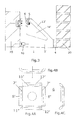
Fig. 1A, 1B, 1C show the brickwork support according to the invention in perspective view, front view, side view and top view respectively; -
Fig. 2A, 2B show in side view sidepiece elements in two different embodiments; -
Fig. 3 shows in side view the brickwork support in mounted position in a cavity wall; -
Fig. 4A, 4B, 4C show in more detail the support bracket in front view, top view and side view; -
Fig. 5A, 5B, 5C show in more detail the adjustment assembly in top view, side view and front view, -
Fig.6A - 6E ,7A - 7E and8A - 8E each show a different embodiment of the bracket anchor provided with two bridge portions, in perspective view with a brickwork carrier and in top view and side view respectively with a brickwork carrier welded thereto, -
Fig.9 shows the bottom part of the locking plate with accompanying slots which are fitting for the edges of the sidepiece elements of the bracket anchor. -
Fig.1A - 1D showbrickwork support 1 according to the invention comprising U-shapedbracket anchor 2 with twosidepiece elements bridge element 9.Brickwork carrier 4 is fixedly attached to the front side of thesidepiece elements brickwork carrier 4 is positioned between the bricks of the outer mortar wall 20 (seefigure 3 ) in order to reduce the pressure forces in a brickwork wall having a great height. Thebrickwork support 1 is connected, by means of mounting means 5 - in this embodiment consisting of a T-head bolt and nut - withanchor rail 31, being the anchoring base. The brickwork support may be connected with the anchoring base in an alternative way, e.g. by means of (chemical) anchors/plugs. Betweenanchor rail 31 and the brickwork support 1 anadjustment plate 30 is mounted so that as a result the position of thebrickwork support 1 may be adjusted to the variations in the brickwork of the outer wall. The horizontal variations in the distance between the anchoring base and the outer wall may also be corrected by means of theadjustment plate 30. - The stiffness of the shown brickwork supports is obtained by interconnecting the
sidepiece elements bridge element 9 or to form thebridge element 9 and thesidepiece elements brickwork carrier 4 and by connecting thebracket anchor 2 onto the anchoring base by means of mounting means 5 in combination with a saddleshaped support bracket 6. As a consequence of its special saddle-shape thesupport bracket 6 will hardly bend under the influence of the occurring forces, e.g. caused by differences in the outside temperature. Therefore thebrickwork support 1 will not quickly become loose or otherwise decrease the required anchoring support to the outer brickwork wall. -
Fig 4A - 4C shows more in detail the support bracket with two pair of adjacent sides oredges 7', 7" en 11', 11". Thefirst edges 7', 7" are provided withflanged rims 8', 8" which are extending backwards or downwards relative to the plane of the drawing. Theadjacent sides 11', 11" are also provided withflanged rims 12', 12" as a result of which thesupport bracket 6 is a very rigid element that will not be deformed as a consequence of the normal pressure load variations in a building construction. In a preferred embodiment thesupport bracket 6 has a rotation symmetric shape, so that is impossible to mound the support bracket incorrectly. - In
figure 3 andfigure 2B an alternative embodiment of thebrickwork support 1 is shown having strut supports 13', 13" which extend from thebridge element 9 to thebrickwork carrier 4. Preferably these strut supports 13', 13" are configured by providingrecesses 14', 14" in thesidepiece elements sidepiece elements bracket anchor 2 to take up higher loads. - When the distance to the anchoring base is great or the brickwork support is out of alignment or is not level, such deviations may be corrected easily by means of a
detachable adjustment assembly 16. -
Figure 1A, 1C and3 show anadjustment assembly 16 andFig.5A - 5C show thepreferred adjustment assembly 16 more in detail. Theadjustment assembly 6 is mounted intorecesses 15', 15" provided at the bottom side of thesidepiece elements Fig.2A and 2B therecess 15" are shown in more detail. Therecesses 15", 15" are preferably square shaped and furthermore provided withconstrictions 17', 17" in order to prevent that the loose, not fixed, adjustment assembly will come out easily or fall from thesidepiece elements 13', 13". When level correction is necessary it is possible during construction to easily slide theadjustment assembly 16 into therecesses 15', 15" by guiding thespindle 19 through theconstriction 17', 17". By rotating thespindle 19, e.g. by means of a screw driver, thestop piece 21 is forced against the anchoringbase 10 so that thebrickwork support 1 may be levelled. Theadjustment assembly 16 and therecesses 15', 15" are preferably square as it has been found that in this way the support forces are transferred in a regular manner and moreover thespindle 19 withstop 21 will always be oriented in the correct mounting position. As shown inFig.5A, 5C thesquare pipe 18 may also have been provided withgrooves 22", 22" for receivingsidepiece elements 3", 3". InFig.1C ,3 is shown that thesidepiece elements grooves 22', 22" in order to constitute an additional structural connection at the bottom side of thebracket anchor 2. - In
figures 6A 6E ,7A - 7E and8A - 8E some alternative embodiments are shown, partly in perspective view and partly in top and side view. Contrary to the abovementioned bracket anchor types the bridge connection between the sidepiece elements now consists of at least one closed bridge element mutually interconnecting the sidepiece elements, the element not being located at the upper side, likebridge element 9 inFig.1A . - Both
bridge element 109 and 109' are clearly visible infig. 6B ,7B and8B . Moreover the lockingplate 106 of flat thick steel plate, at the front side of the bracket anchor, has a flat shape and is at its front side provided with twoparallel slots 104, 104' for fittingly receiving the raisededges 103, 103' of the side piece elements. At the entrance side the edges of the slots are slightly bevelled off as is visible inFig. 6D ,7D ,8D . This embodiment, as shown inFig.9 , has the advantage that the bracket anchor may take up considerably more force. - In
Fig. 6C ,7C and8C two bracket anchors are shown whereupon abrickwork carrier 104 is welded.Fig. 6E ,7E and8E show in side view the bracket anchor with the thereto fixedly weldedbrickwork carrier 104 andFig. 6D ,7D ,8D show a top view of the bracket anchor.
Claims (9)
- Brickwork support assembly (1) for anchoring and/or support of a brick (outer) wall onto a anchoring base (10), like a concrete inner wall or concrete skeleton structure, comprising:- a bracket anchor (2) provided with two essentially parrallely sidepiece elements (3', 3");- a brickwork carrier (4) suitable for incorporating into a brickwork wall (20), the carrier (4) being fixedly attached with the front side of the sidepiece elements (3', 3");- mounting means (5), like a screw bolt with nut, for mounting the bracket anchor (2) onto the anchoring base (10);- a support bracket (6) for the mounting means (5), the opposing edges (7', 7") of the bracket are provided with first flanged rims (8', 8"), extending in the same direction around the sidepiece elements (3', 3");characterized in that- the sidepiece elements (3'. 3") with their upper sides are interconnected by a bridge element (9) or
the bracket anchor (2) is a one piece construction having a U-shape with downwards extending leg portions (3', 3");- the support bracket (6) is provided with a saddle-shape, by providing the adjacent edges (7', 7") - of the edges having the first flanged rims (8', 8") - with second flanged rims (12', 12") extending in the opposite direction relative to the first flanged rims (8', 8"). - Brickwork support assembly according to claim 1, wherein the saddle-shaped support bracket is rotation symmetric.
- Brickwork support assembly according to claim 1 or 2, wherein the sidepiece elements are provided with strut supports (13', 13") connected with the bridge element (9) or the sidepiece elements (3', 3") of the U-shape are provided with large recesses (14', 14") configuring strut supports (13', 13").
- Brickwork support assembly according to claim 1 or 2, wherein the sidepiece elements (3', 3") at their rearward side (anchoring side) are provided with recesses (15', 15") for mounting an adjustment assembly (16).
- Brickwork support assembly according to claim 3, wherein the recesses (15', 15") are provided with a constriction (17', 17") at the rearward side of the sidepiece portions (3', 3").
- Brickwork support assembly according to claim 3, wherein the assembly (1) is provided with a detachable adjustment assembly (16) configured to be mounted into the recesses (15', 15'") of the sidepiece elements (3', 3").
- Brickwork support assembly according to claim 5, wherein the adjustment assembly (16) comprises: a square pipe (18), a spindle (19) with a stop piece (21) for the anchoring base (10).
- Brickwork support assembly according to claim 6, wherein the pipe (18) is provided with grooves (22", 22") for receiving the side piece elements (3', 3").
- Brickwork support assembly for anchoring and/or support of a brick (outer) wall onto a anchoring base, like a concrete inner wall or concrete skeleton structure, comprising:- a bracket anchor provided with two essentially parrallelly sidepiece elements;- a brickwork carrier suitable for incorporating into a brickwork wall, the carrier being fixedly attached with the front side of the sidepiece elements;- mounting means, like a screw bolt with nut, for mounting the bracket anchor onto the anchoring base;- a support plate of a flat thick steel plate wherein two parallelly slots are mounted for receiving the raised edges of the side piece elements;characterized in that
the sidepiece elements at their rearward side are mutually interconnected by at least one bridge element, preferably two bridge elements, whereby the first bridge element is positioned nearby the upper side of the bracket anchor and the second bridge element is positioned at some distance thereof nearby the bottom part of the sidepiece element. (Fig.6B, 7B, 8B)
Applications Claiming Priority (1)
| Application Number | Priority Date | Filing Date | Title |
|---|---|---|---|
| NL341279 | 2007-07-13 |
Publications (1)
| Publication Number | Publication Date |
|---|---|
| EP2017400A1 true EP2017400A1 (en) | 2009-01-21 |
Family
ID=39761112
Family Applications (1)
| Application Number | Title | Priority Date | Filing Date |
|---|---|---|---|
| EP08012550A Withdrawn EP2017400A1 (en) | 2007-07-13 | 2008-07-11 | Brickwork support bracket |
Country Status (1)
| Country | Link |
|---|---|
| EP (1) | EP2017400A1 (en) |
Citations (5)
| Publication number | Priority date | Publication date | Assignee | Title |
|---|---|---|---|---|
| DE2849376A1 (en) * | 1978-11-14 | 1980-06-04 | Hilti Ag | DEVICE FOR FASTENING PANEL PANELS |
| EP0235757A2 (en) * | 1986-02-27 | 1987-09-09 | Siegfried Fricker | Supporting bracket |
| EP0212228B1 (en) * | 1985-08-28 | 1991-05-29 | Unistrut Europe PLC | Device for anchoring slabs |
| EP0869232A1 (en) * | 1997-04-01 | 1998-10-07 | Hakron Verankeringstechniek B.V. | Console assembly |
| DE10117199A1 (en) * | 2001-04-05 | 2002-10-10 | Willi Jung | Face brick support system made of metal comprises an individual support fixed on a wall and having a receiving opening into which a rail is inserted and held in place |
-
2008
- 2008-07-11 EP EP08012550A patent/EP2017400A1/en not_active Withdrawn
Patent Citations (5)
| Publication number | Priority date | Publication date | Assignee | Title |
|---|---|---|---|---|
| DE2849376A1 (en) * | 1978-11-14 | 1980-06-04 | Hilti Ag | DEVICE FOR FASTENING PANEL PANELS |
| EP0212228B1 (en) * | 1985-08-28 | 1991-05-29 | Unistrut Europe PLC | Device for anchoring slabs |
| EP0235757A2 (en) * | 1986-02-27 | 1987-09-09 | Siegfried Fricker | Supporting bracket |
| EP0869232A1 (en) * | 1997-04-01 | 1998-10-07 | Hakron Verankeringstechniek B.V. | Console assembly |
| DE10117199A1 (en) * | 2001-04-05 | 2002-10-10 | Willi Jung | Face brick support system made of metal comprises an individual support fixed on a wall and having a receiving opening into which a rail is inserted and held in place |
Similar Documents
| Publication | Publication Date | Title |
|---|---|---|
| US20030217521A1 (en) | Adjustable anchoring system for a wall | |
| CN207160344U (en) | A kind of plug-in PC wallboard connecting mechanisms of dot point parallel-moving type and device | |
| CN103850352A (en) | Connection method of prefabricated slab | |
| US7730690B2 (en) | Compression post assembly for wind up-lift of suspension soffits | |
| US8151528B2 (en) | System and method for anchoring a modular building | |
| KR20160001216A (en) | Rahmen using hinge type pc wall and method for constructing the same | |
| JP4083773B2 (en) | Construction method of concrete / steel composite truss bridge | |
| EP2017400A1 (en) | Brickwork support bracket | |
| EP2935712B1 (en) | Column shoe | |
| CA2888404A1 (en) | Support bracket apparatus | |
| US20120011781A1 (en) | Perimeter wall support system for a manufactured home | |
| EP3176349B1 (en) | Anti-lifting coupling system | |
| CN211523699U (en) | Elevation floor and elevation floor node connection structure falls | |
| CN210713801U (en) | Pre-buried device of climbing awl embedding piece in special-shaped climbing frame system | |
| JP4296545B2 (en) | Center-pillar structure of eyeglass tunnel | |
| KR102156678B1 (en) | Prefabriated footbridge | |
| NL1034127C2 (en) | Masonry support assembly. | |
| EP3710644A1 (en) | Anchoring device for structural profiles | |
| JP5904051B2 (en) | Thin plate lightweight steel structure bearing wall fixing structure | |
| AU2006203541B2 (en) | Composite steel joist & concrete construction system | |
| JP6800764B2 (en) | Foundation members | |
| JP5281463B2 (en) | Structure of load-bearing frame, manufacturing method and building adjustment method using this load-bearing frame | |
| KR20160043501A (en) | A sump or elevator pit under structure | |
| KR101574628B1 (en) | Reinforcement structure of the steel beam | |
| KR20090003182U (en) | The support of a mold |
Legal Events
| Date | Code | Title | Description |
|---|---|---|---|
| PUAI | Public reference made under article 153(3) epc to a published international application that has entered the european phase |
Free format text: ORIGINAL CODE: 0009012 |
|
| AK | Designated contracting states |
Kind code of ref document: A1 Designated state(s): AT BE BG CH CY CZ DE DK EE ES FI FR GB GR HR HU IE IS IT LI LT LU LV MC MT NL NO PL PT RO SE SI SK TR |
|
| AX | Request for extension of the european patent |
Extension state: AL BA MK RS |
|
| 17P | Request for examination filed |
Effective date: 20090721 |
|
| 17Q | First examination report despatched |
Effective date: 20090812 |
|
| AKX | Designation fees paid |
Designated state(s): AT BE BG CH CY CZ DE DK EE ES FI FR GB GR HR HU IE IS IT LI LT LU LV MC MT NL NO PL PT RO SE SI SK TR |
|
| RAP1 | Party data changed (applicant data changed or rights of an application transferred) |
Owner name: AWBA B.V. |
|
| RAP1 | Party data changed (applicant data changed or rights of an application transferred) |
Owner name: JACOBS, JOHANNES ARNOLDUS PETRUS MARIA |
|
| RAP1 | Party data changed (applicant data changed or rights of an application transferred) |
Owner name: CERTACON B.V. |
|
| STAA | Information on the status of an ep patent application or granted ep patent |
Free format text: STATUS: THE APPLICATION IS DEEMED TO BE WITHDRAWN |
|
| 18D | Application deemed to be withdrawn |
Effective date: 20120324 |