EP2017179A1 - Container for consumer goods with connector - Google Patents
Container for consumer goods with connector Download PDFInfo
- Publication number
- EP2017179A1 EP2017179A1 EP07252889A EP07252889A EP2017179A1 EP 2017179 A1 EP2017179 A1 EP 2017179A1 EP 07252889 A EP07252889 A EP 07252889A EP 07252889 A EP07252889 A EP 07252889A EP 2017179 A1 EP2017179 A1 EP 2017179A1
- Authority
- EP
- European Patent Office
- Prior art keywords
- pack
- packs
- wall
- connector
- edges
- Prior art date
- Legal status (The legal status is an assumption and is not a legal conclusion. Google has not performed a legal analysis and makes no representation as to the accuracy of the status listed.)
- Withdrawn
Links
Images


Classifications
-
- B—PERFORMING OPERATIONS; TRANSPORTING
- B65—CONVEYING; PACKING; STORING; HANDLING THIN OR FILAMENTARY MATERIAL
- B65D—CONTAINERS FOR STORAGE OR TRANSPORT OF ARTICLES OR MATERIALS, e.g. BAGS, BARRELS, BOTTLES, BOXES, CANS, CARTONS, CRATES, DRUMS, JARS, TANKS, HOPPERS, FORWARDING CONTAINERS; ACCESSORIES, CLOSURES, OR FITTINGS THEREFOR; PACKAGING ELEMENTS; PACKAGES
- B65D5/00—Rigid or semi-rigid containers of polygonal cross-section, e.g. boxes, cartons or trays, formed by folding or erecting one or more blanks made of paper
- B65D5/009—Rigid or semi-rigid containers of polygonal cross-section, e.g. boxes, cartons or trays, formed by folding or erecting one or more blanks made of paper the container body comprising a set of interconnected cells, e.g. hinged one to another
-
- B—PERFORMING OPERATIONS; TRANSPORTING
- B65—CONVEYING; PACKING; STORING; HANDLING THIN OR FILAMENTARY MATERIAL
- B65D—CONTAINERS FOR STORAGE OR TRANSPORT OF ARTICLES OR MATERIALS, e.g. BAGS, BARRELS, BOTTLES, BOXES, CANS, CARTONS, CRATES, DRUMS, JARS, TANKS, HOPPERS, FORWARDING CONTAINERS; ACCESSORIES, CLOSURES, OR FITTINGS THEREFOR; PACKAGING ELEMENTS; PACKAGES
- B65D21/00—Nestable, stackable or joinable containers; Containers of variable capacity
- B65D21/02—Containers specially shaped, or provided with fittings or attachments, to facilitate nesting, stacking, or joining together
- B65D21/0201—Containers specially shaped, or provided with fittings or attachments, to facilitate nesting, stacking, or joining together stackable or joined together side-by-side
-
- B—PERFORMING OPERATIONS; TRANSPORTING
- B65—CONVEYING; PACKING; STORING; HANDLING THIN OR FILAMENTARY MATERIAL
- B65D—CONTAINERS FOR STORAGE OR TRANSPORT OF ARTICLES OR MATERIALS, e.g. BAGS, BARRELS, BOTTLES, BOXES, CANS, CARTONS, CRATES, DRUMS, JARS, TANKS, HOPPERS, FORWARDING CONTAINERS; ACCESSORIES, CLOSURES, OR FITTINGS THEREFOR; PACKAGING ELEMENTS; PACKAGES
- B65D5/00—Rigid or semi-rigid containers of polygonal cross-section, e.g. boxes, cartons or trays, formed by folding or erecting one or more blanks made of paper
- B65D5/42—Details of containers or of foldable or erectable container blanks
- B65D5/427—Individual packages joined together, e.g. by means of integral tabs
-
- B—PERFORMING OPERATIONS; TRANSPORTING
- B65—CONVEYING; PACKING; STORING; HANDLING THIN OR FILAMENTARY MATERIAL
- B65D—CONTAINERS FOR STORAGE OR TRANSPORT OF ARTICLES OR MATERIALS, e.g. BAGS, BARRELS, BOTTLES, BOXES, CANS, CARTONS, CRATES, DRUMS, JARS, TANKS, HOPPERS, FORWARDING CONTAINERS; ACCESSORIES, CLOSURES, OR FITTINGS THEREFOR; PACKAGING ELEMENTS; PACKAGES
- B65D85/00—Containers, packaging elements or packages, specially adapted for particular articles or materials
- B65D85/07—Containers, packaging elements or packages, specially adapted for particular articles or materials for compressible or flexible articles
- B65D85/08—Containers, packaging elements or packages, specially adapted for particular articles or materials for compressible or flexible articles rod-shaped or tubular
- B65D85/10—Containers, packaging elements or packages, specially adapted for particular articles or materials for compressible or flexible articles rod-shaped or tubular for cigarettes
- B65D85/1036—Containers formed by erecting a rigid or semi-rigid blank
- B65D85/1063—Containers formed by erecting a rigid or semi-rigid blank so as to form two cigarette-compartments interconnected by a hinge-portion
Definitions
- the present invention relates to a container for smoking articles comprising at least two hingedly connected packs, each for housing a separate bundle of smoking articles.
- WO-A-2006/079799 discloses packages comprising two packs connected in a Jacob's ladder arrangement by at least first and second straps and blanks and a method for forming such packages.
- WO-A-2006/079799 describes a package comprising: first and second packs each capable of containing items, each pack having a first face bound by a first edge and a second edge, the second edge being parallel to the first edge; and means, connecting the first and second packs, which means compising first and second straps which are attachable to the first and second packs; wherein, in a first position of the packs the first face of the first and second packs face each other with the first edges of the first and second pack adjacent to each other and the second edges of the first and second pack adjacent each other, the first and second straps extending across the first face and being hinged about the first and second edges, wherein the first strap is hinged about the first edge of the first pack and hinged about the second edge of the second pack and the second strap is hinged about the second edge of the first pack and hinged about the first edge of the second pack, whereby the first and second packs are movable, one relative to the other between at least the first position, a second position in which the second pack is rotated
- WO-A-2006/079799 describes a blank for forming the means comprising first and second straps that connects the first and second packs of the package, which comprises a single sheet of material, having at least a first region providing a first strap and a second region providing a second strap, the regions being adjoined by a line operable to separate the first region from the second region, the line having a first, second and third section thereon, the second section being a weakened section such that the first and second regions are separable, and the first and second sections being cut portions extending from respective ends of the weakened section to the edge of the sheet.
- WO-A-2006/079799 describes another blank for forming the means comprising first and second straps that connects the first and second packs of the package, which comprises a single sheet of material having a first elongate section in which there is an elongate hole having major edges which are spaced apart and a second section aligned with the hole and extending from a minor edge of the first section, the second section having a maximum width substantially equal or less than the minimum width of the hole and a length greater than the length of the hole such that a free minor edge of the second section is threadable through the hole and capable of attaching to the free minor edge of the first section.
- the first and second packs of all of the packages described in the specification and shown in the drawings of WO-A-2006/079799 are connected in a Jacobs Ladder arrangement by a separate joining blank or by a separate Jacobs Ladder structure.
- a separate joining blank is either fixed to the first and second packs or the first and second packs are positioned within, and in some cases fixed to, two pack containing sections in a separate Jacobs Ladder structure.
- a container for smoking articles comprising at least two hingedly connected packs, each for housing a separate bundle of smoking articles, the container comprising: a first pack having a first wall with opposed first and second edges; a second pack having a first wall with opposed first and second edges; and a connector extending between the first edge of the first wall of the first pack and the second edge of the first wall of the second pack, wherein the connector is hingeable relative to the first pack about the first edge of the first wall of the first pack and hingeable relative to the second pack about the second edge of the first wall of the second pack between a first position, in which the first edges of the first walls of the first and second packs are adjacent and the second edges of the first walls of the first and second packs are adjacent, and a second position, in which the first edges of the first walls of the first and second packs are spaced apart and the second edges of the first walls of the first and second packs are spaced apart.
- the connector In the first position, the connector overlies the first walls of the first and second packs and the first walls of the first and second packs are parallel and opposed. In the second position, the first walls of the first and second packs and the connector are substantially coplanar.
- the first pack and the second pack of containers according to the second aspect of the invention are hingeable relative to one another about the first edges of the first walls of the first and second packs between the first position and a third position, in which the first edges of the first walls of the first and second packs are adjacent and the second edges of the first walls of the first and second packs are spaced apart.
- the connector In the third position, the connector overlies the first wall of the second pack and the first walls of the first and second packs are substantially coplanar.
- the first pack and the second pack of containers according to the second aspect of the invention are also hingeable relative to one another about the second edges of the first walls between the first position and a fourth position, in which the second edges of the first walls of the first and second packs are adjacent and the first edges of the first walls of the first and second packs are spaced apart.
- the connector In the fourth position, the connector overlies the first wall of the first pack and the first walls of the first and second packs are substantially coplanar.
- the first pack and the second pack of containers according to the invention are thus advantageously hingedly connected in a double hinged manner not dissimilar to a Jacob's ladder arrangement by the connector.
- This provides containers according to the invention with an interesting opening mechanism, while at the same time keeping their manufacturing costs low due to the simple design.
- first pack and the second pack of containers according to the invention may be a slide and shell pack comprising an outer shell and an inner slide within the outer shell.
- first pack and the second pack of containers according to the first aspect of the invention may be a hinge-lid pack comprising a lower box portion and an upper lid portion hinged to the lower box portion.
- the connector is preferably of substantially the same dimensions as the first wall of the first pack.
- the connector of the second pack is preferably of substantially the same dimensions as the first wall of the second pack.
- the connector is preferably of substantially the same dimensions as the lower box portion of the first wall of the first pack.
- the connector is preferably of substantially the same dimensions as the lower box portion of the first wall of the second pack.
- the first pack and the second pack of containers according to the invention are both slide and shell packs or both hinge-lid packs.
- containers according to the invention may comprise a first pack and a second pack provided with different types of opening and closing means.
- the first pack may be a hinge-lid pack and the second pack may be a slide and shell pack.
- the first pack may have a hinge-lid pivotable about a hinge line extending across the first wall of the first pack and the second pack may have a hinge-lid pivotable about a hinge line extending across the first wall of the second pack.
- the first pack may have a hinge-lid pivotable about a hinge line extending across a second wall of the first pack that is parallel and opposed to the first wall of the first pack and the second pack may have a hinge-lid pivotable about a hinge line extending across a second wall of the second pack that is parallel and opposed to the first wall of the second pack.
- the connector of containers according to the invention may be integral with the first pack, integral with the second pack or integral with the first pack and the second pack.
- first pack and the second pack are slide and shell packs and the connector and the outer shell of one of the first pack and the second pack are formed from a first blank and the outer shell of the other of the first pack and the second pack is formed from a second blank.
- first pack and the second pack are slide and shell packs and the outer shell of the first pack, the outer shell of the second pack and the connector are formed from a single blank.
- first pack and the second pack are hinge-lid packs and the connector and one of the first pack and the second pack are formed from a first blank and the other of the first pack and the second pack is formed from a second blank.
- first pack and the second pack are hinge-lid packs and the first pack, the second pack and the single connector are formed from a single blank.
- first pack, the second pack and the connector of containers according to the invention may be formed from separate blanks.
- the connector is preferably adhered to the first pack and the second pack in order to form the container.
- the connector may, for example, be adhered to the first pack and the second pack using hot melt adhesive, contact adhesive or double sided adhesive tape.
- Containers according to the invention preferably further comprise retention means to provide resistance to movement of the first and second packs from the first position to the second third or fourth position, such that a positive force must be applied by a consumer to hinge the first and second packs relative to one another from the first position to the second, third and fourth position.
- containers according to the invention may comprise retention means which provides a positive force that urges movement of the first pack and the second pack towards the first position.
- first pack and the second pack of containers according to the invention may be releasably connected in the first position by the releasable engagement of first retention means provided on the first pack and second retention means provided on the second pack.
- the first retention means and the second retention means may comprise any suitable known magnetic fasteners, mechanical fasteners, adhesive fasteners or combinations thereof.
- the first retention means and the second retention means may comprise one or more releasable pressure-actuated hook-and-loop type fasteners, snap fasteners or other mating plug (male) and socket (female) type fasteners.
- the opposed first and second edges of the first wall of the first pack and the opposed first and second edges of the first wall of the second pack are longitudinal edges of the packs. More preferably, the opposed first and second edges of the first wall of the first pack and the opposed first and second edges of the first wall of the second pack are longitudinal vertical edges of the packs.
- Containers according to the invention may comprise two or more hingedly connected packs, each for housing a bundle of smoking articles, for example cigarettes, such as conventional lit-end cigarettes or cigarettes for use with electrical smoking systems (for example cigarettes of the type disclosed in US-A-5 692 525 ), cigars or cigarillos.
- containers according to the invention comprise two or more hingedly connected packs, each for housing a separate bundle of cigarettes.
- the first pack and the second pack of containers according to the invention may be designed to house separate bundles of different numbers of cigarettes.
- the first pack and the second pack of containers according to the invention may be designed to house separate bundles of cigarettes of different dimensions (for example, cigarettes of different length or different circumference).
- the first pack and the second pack of containers according to the invention may, for example, be designed to house separate bundles of different numbers of short (between about 70 mm and about 75 mm in length), regular size (about 80mm in length), king size (about 84 mm in length), super-king size, slim, super-slim or wide cigarettes.
- containers according to the invention may also be designed to hold different total numbers of smoking articles.
- containers for cigarettes according to the invention may comprise a first pack and a second pack for housing, in combination, a total of twenty or twenty-one regular size cigarettes.
- containers for cigarettes according to the invention may comprise a first pack and a second pack for housing, in combination, a total of seventeen or eighteen wide cigarettes.
- the length, width and depth of the first pack and the second pack of containers according to the invention may be such that, when in the initial position, the resultant overall dimensions of the containers are similar to, or substantially the same as, the dimensions of a conventional disposable pack of smoking articles.
- the length, width and depth of the first pack and the second pack may be such that, in the initial or first position, the resultant overall dimensions of the container are similar to the dimensions of a conventional disposable hinge-lid pack of twenty cigarettes.
- Containers according to the invention may advantageously comprise first packs and second packs for housing separate bundles of smoking articles of different types.
- a wide variety of different types of cigarettes are produced and sold.
- different types of tobacco having unique characteristic tastes and aromas such as Burley, Oriental and Virginia tobacco, are used alone or in varying amounts in tobacco blends to produce brands of cigarettes having different characteristic tastes.
- both plain cigarettes and cigarettes having many different types of filter tips are manufactured as well as cigarettes of differing length (for example, regular size, king size or super-king size), circumference (for example, slim or super-slim), strength of taste, resistance to draw and total particulate matter delivery.
- cigarettes containing flavourings such as menthol are also available.
- Containers according to the invention may comprise first packs and second packs for housing separate bundles of cigarettes of a different tobacco blend or flavour.
- containers according to the invention may comprise first packs and second packs for housing separate bundles of cigarettes of a different size (different length, different circumference or both different length and different circumference).
- the first pack and the second pack of containers according to the invention may be of the same or different cross-section.
- one or both of the first pack and the second pack of containers according to the invention may be rectangular, square, triangular, pentagonal, hexagonal, D-shaped, semi-circular or semi-oval in cross-section.
- first pack and the second pack of containers according to the invention are substantially parallelepipedal. More preferably, the first pack and the second pack of containers according to the invention are substantially cuboid.
- the first pack and the second pack of containers according to the invention may have one or more right-angled longitudinal edges, one or more right-angled transverse edges, one or more rounded longitudinal edges, one or more rounded transverse edges, one or more bevelled longitudinal edges, one or more bevelled transverse edges or any suitable combination thereof.
- the first pack and the second pack of containers according to the invention are of substantially the same shape.
- the dimensions of the first pack and the second pack of containers according to the invention may be the same or different.
- the first pack and the second pack of containers according to the invention are of different dimensions. More preferably, the first pack and the second pack of containers according to the invention are of substantially the same length and width, but of different depth.
- the first wall of the first pack and the first wall of the second pack of containers according to the invention are of substantially the same dimensions.
- the first wall of the first pack and the first wall of the second pack are major walls of the packs.
- the first wall of the first pack is a front wall or a rear wall of the first pack.
- the first wall of the second pack is a front wall or a rear wall of the second pack.
- the first pack and the second pack of containers according to the invention are preferably formed from one or more folded laminar blanks, more preferably from one or more folded laminar cardboard blanks.
- the exterior surfaces of the first packs, second packs and connectors of containers according to the invention may be printed, embossed, debossed or otherwise embellished (for example using labels or stickers) with manufacturer or brand logos, trade marks, slogans and other consumer information and indicia. It will be appreciated that the same or different manufacturer and brand logos, trade marks, slogans, and other consumer information and indicia may be applied to the exterior surfaces of the first packs, second packs and connectors.
- the connectors of containers according to the invention may be formed from one or more suitable materials including, but not limited to, paperboard, cardboard, plastic, metal (such as, for example, aluminium), transparent or opaque foil (such as, for example, polyethylene (PE) or polyethylene terephthalate (PET) foils) and laminated material (such as, for example, paper/aluminium, plastic/paper/aluminium or other laminates).
- suitable materials including, but not limited to, paperboard, cardboard, plastic, metal (such as, for example, aluminium), transparent or opaque foil (such as, for example, polyethylene (PE) or polyethylene terephthalate (PET) foils) and laminated material (such as, for example, paper/aluminium, plastic/paper/aluminium or other laminates).
- Containers according to the invention may comprise connectors having one or more windows or cut-outs provided therein.
- the one or more windows or cut-outs interact or cooperate with images provided on the first walls of the first packs, second packs or first and second packs of the containers to generate further images.
- Containers according to the invention may comprise more than two packs. Third and subsequent packs of containers according to the invention may be connected to one or more other packs thereof in the same or a different manner to that in which the first pack and the second pack are hingedly connected.
- containers according to the invention comprise three or more packs
- each pack of the container is hingedly connected in a double hinged manner to at least one other pack thereof by a connector.
- containers according to the invention may comprise three, four, five or six packs hingedly connected by two, three, four or five connectors, respectively, wherein each pack of the container is hingedly connected in a double hinged manner to either one or two other packs thereof.
- Figures 2a, 2b , 3 , 4a, 4b , 5 and 6 show blanks for forming containers or parts of containers according to embodiments of the invention.
- solid lines are used to denote cut lines or outer borders of the blanks.
- Dashed lines are used to denote lines, which are formed by compressing or partially cutting the material of the blanks by creasing, scoring, embossing or an equivalent process, along which the blanks are bent upon erection of the containers or parts of containers formed there from or which act as hinge.
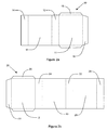
- the container according to the first embodiment of the invention shown in Figures 1a and 1b comprises two hingedly connected cuboid slide and shell packs.
- the container comprises a first pack 2 having an outer shell 3 and an inner slide 4 within the outer shell 3 and a second pack 5 having an outer shell 6 and an inner slide 7 within the outer shell 6, which are connected in a double hinged manner not dissimilar to a Jacob's ladder arrangement.
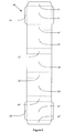
- FIG. 2a An elongate blank 10 for forming the outer shell 3 of the first pack 2 is shown in Figure 2a .
- the blank 10 comprises a rear wall panel 11, a left side wall panel 12, a front wall panel 13, and a right side wall panel 14, which are separated from one another in the longitudinal direction of the blank 10 by vertical fold lines (shown as dashed lines in Figure 2a ).
- a pair of rear wall flaps 15 are connected to the upper and lower edges of the rear wall 11 along horizontal fold lines and a right side wall flap 16 is connected to the side of the rear wall panel 11 along a vertical fold line.
- FIG. 2b An elongate blank 20 for forming the outer shell 6 of the second pack 5 is shown in Figure 2b .
- the blank 20 for forming the outer shell 6 of the second pack 5 is of similar construction to the blank 10 for forming the outer shell 3 of the first pack 2 and comprises a rear wall panel 21, a right side wall panel 24, a front wall panel 23, and a left side wall panel 22, which are separated from one another in the longitudinal direction of the blank 20 by vertical fold lines.
- a pair of rear wall flaps 25 are connected to the upper and lower edges of the rear wall panel 21 along horizontal fold lines and a left side wall flap 27 is connected to the side of the rear wall panel 21 along a vertical fold line.
- the blank 20 for forming the outer shell 6 of the second pack 5 also includes a single connector panel 28 connected to the left side wall panel 22 along a vertical fold line and a connector flap 29 connected to the single connector panel 28 along a vertical fold line.
- the rear wall flaps 15 are folded inwardly through 180 degrees about the horizontal fold lines.
- the right side wall flap 16, rear wall panel 11, left side wall panel 12, front wall panel 13 and right side wall panel 14 are folded through 90 degrees about the vertical fold lines and the outer surface of the right side wall flap 16 is affixed to the inner surface of the right side wall panel 14.
- the rear wall flaps 25 are folded inwardly through 180 degrees about the horizontal fold lines.
- the left side wall flap 27, rear wall panel 21, right side wall panel 24, front wall panel 23 and left side wall panel 22 are folded through 90 degrees about the vertical fold lines and the outer surface of the left side wall flap 27 is adhered to the inner surface of the left side wall panel 22.
- the inwardly folded rear wall flaps 15, 25 may be affixed to the inner surface of the rear wall panels 11, 21 of the blanks 10, 20 during erection of the outer shells 3, 6 of the first pack 2 and the second pack 5.
- the outer surface of the connector flap 29 of the blank 20 is affixed to the outer surface of the left side wall panel 12 of the outer shell 3 of the first pack 2.
- the inner slides 4, 7 of the first pack 2 and the second pack 5 are filled with a bundle of smoking articles and placed inside the erected outer shells 3, 6 before the outer shells 3, 6 of the first pack 2 and the second pack 5 are connected to one another.
- the bundles of smoking articles in the inner slides 4, 7 of the first pack 2 and the second pack 5 advantageously improve the stability of the container.
- the connected outer shells 3, 6 of the first 2 and second 5 packs are hingeable relative to one another about the longitudinal edges of the rear walls 11, 21 of the outer shells 3, 6 from a first position (not shown) to the positions shown in Figures 1a and 1b .
- the rear walls 11, 21, of the first 2 and second 5 packs are parallel and opposed and the connector 28 extends between and overlies the rear walls 11, 21 of the first 102 and second 105 packs.
- the connector 28 In the positions shown in Figures 1 a and 1 b the connector 28 only overlies the rear wall 21 of the second pack 5 and the rear wall 11 of the first pack 2, respectively.
- the connected outer shells 3, 6 of the first 2 and second 5 packs are also hingeable relative to one another about the longitudinal edges of the rear walls 11, 21 of the outer shells 3, 6 from the first position to a position (not shown) in which the connector 28 does not overlie the rear wall 21 of the second pack 5 or the rear wall of the first pack 2 and the rear walls 11, 21, of the first 2 and second 5 packs and the connector 28 are substantially coplanar.
- FIG 3 shows a blank 40 for forming the inner slides 4, 7, of the first slide and shell pack 2 and the second slide and shell pack 5 of the container according to the first embodiment of the invention shown in Figures 1a and 1b .
- a flap 41 is cut from the lower portion of the major wall of the inner slide 4, 7.
- the flap 41 is connected to the major wall of the inner slide 4, 7 along a horizontal fold line. During erection of the inner slide, the flap 41 is folded outwardly through 180 degrees about the horizontal fold line.
- the leading surface of the outwardly folded flap 41 extending from the major wall of the inner slide 4, 7 engages the corresponding facing surface of the rear wall flap 15, 25 extending inwardly from the upper edge of the rear wall 11, 21 of the respective outer shell 3, 6.
- Engagement of the rear wall flap 15, 25 of the outer shell 3, 6 by the flap 41 of the inner slide 4, 7 advantageously restricts further upward movement of the inner slide 4, 7 within the outer shell 3, 6, and so prevents removal of the inner slide 4, 7 from the upper end of the outer shell 3, 6.
- Figures 4a and 4b show the inner surfaces of two blanks for forming a container according to a second embodiment of the invention (not shown), which comprises a first hinge-lid pack and a second hinge-lid pack connected in a double hinged manner not dissimilar to a Jacob's ladder arrangement.
- the first hinge-lid pack and the second hinge-lid pack of the container according to the second embodiment of the invention are connected in the same manner as the outer shell 3 of the first slide and shell pack 2 and the outer shell 6 of the second slide and shell pack 5 of the container according to the first embodiment of the invention shown in Figure s 1 a and 1 b.
- the final digits of the reference numerals for the panels of the blanks 5140, 60 for forming the first hinge-lid pack and the second hinge-lid pack of the container according to the second embodiment of the invention shown in Figures 4a and 4b are the same as the final digits of the reference numerals for the corresponding panels of the blanks 10, 20 for forming the outer shell 3 of the first slide and shell pack 2 and the outer shell 6 of the second slide and shell pack 5 of the container according to the first embodiment of the invention shown in Figures 2a and 2b , respectively.
- Figure 5 shows a blank 70 for forming a separate connector of a container according to a third embodiment of the invention, which is formed from at least three blanks.
- the blank comprises a central connector panel 78, a first connector flap 79a connected to the right side edge of the connector panel 78 along a vertical fold line and a second connector flap 79b connected to the left side edge of the connector panel 78 along a vertical fold line.
- the connector panel 78 of the blank 70 is placed between a first wall of a first pack and the a first wall of a second pack of the container.
- the second connector flap 79b of the blank 70 is folded through 90 degrees about the vertical fold line connecting it to the side edge of the connector panel 78 and affixed to a second wall of the first pack, which is adjacent and substantially perpendicular to the first wall thereof.
- the first connector panel 79a of the blank 70 is folded through 90 degrees about the vertical fold line connecting it to the side edge of the connector panel 78 and affixed to a second wall of the second pack, which is adjacent and substantially perpendicular to the first wall thereof.
- the second connector flap 79b may be affixed to the second wall of the first pack and the second pack then placed on the first pack so that the first wall of the second pack overlies the connector panel 78 and first wall of the first pack.
- the first connector panel 79a of the blank 70 is then folded through 90 degrees about the vertical fold line connecting it to the side edge of the connector panel 78 and affixed to the second wall of the second pack.
- the first connector panel 79a and the second connector panel 79b may be substantially the same size as the second walls of the first and second packs, respectively, to which they are attached.
- the first connector panel 79a and the second connector panel 79b may be of reduced size compared to the second walls of the first and second packs to which they are attached to, for example, accommodate a hinge line where the first and second packs are hinge-lid packs.
- Figure 6 shows a blank 80 for forming a container according to a fourth embodiment of the invention (not shown), which comprises a first slide and shell pack and a second slide pack and shell pack connected in a double hinged manner not dissimilar to a Jacob's ladder arrangement.
- the outer shell of the first slide and shell pack and the outer shell of the second slide and shell pack of the container according to the fourth embodiment of the invention are connected in a similar manner as the outer shell 3 of the first slide and shell pack 2 and the outer shell 6 of the second slide and shell pack 5 of the container according to the first embodiment of the invention shown in Figures 1a and 1b .
- the outer shell of the first slide and shell pack, the outer shell of the second slide and shell pack and the connector of the container according to the fourth embodiment of the invention are formed from a single one-piece blank 80.
- the digits of the reference numerals for the panels of the blank 80 for forming the first slide and shell pack and the second slide and shell pack of the container according to the fourth embodiment of the invention shown in Figure 6 are the same as those of the reference numerals for the corresponding panels of the blanks 10, 20 for forming the outer shell 3 of the first slide and shell pack 2 and the outer shell 6 of the second slide and shell pack 05, respectively, of the container according to the first embodiment of the invention shown in Figures 2a and 2b .
- the rear wall flaps 15' are folded inwardly through 180 degrees about the horizontal fold lines.
- the left side wall flap 17', rear wall panel 11', right side wall panel 14', front wall panel 13' and left side wall panel 12' and are folded through 90 degrees about the vertical fold lines and the inner surface of the left side wall flap 17' is affixed to the outer surface of the left side wall panel 12'.
- the rear wall flaps 25' are folded inwardly through 180 degrees about the horizontal fold lines.
- the left side wall flap 27', rear wall panel 21', right side wall panel 24', front wall panel 23' and left side wall panel 22' are folded through 90 degrees about the vertical fold lines and the outer surface of the left side wall flap 27' is adhered to the inner surface of the left side wall panel 22'.
Abstract
A container for smoking articles comprises at least two hingedly connected packs, each for housing a separate bundle of smoking articles. The container comprises: a first pack (2) having a first wall (11, 11', 51) with opposed first and second edges; a second pack (5) having a first wall (21, 21', 61) with opposed first and second edges; and a connector (28, 28', 68, 78) extending between the first edge of the first wall (11, 11', 51) of the first pack (2) and the second edge of the first wall (21, 21', 61) of the second pack (5). The connector (28, 28', 68, 78) is hingeable relative to the first pack (2) about the first edge of the first wall (11, 11', 51) of the first pack (2) and hingeable relative to the second pack (5) about the second edge of the first wall (21, 21', 61) of the second pack (5) between a first position, in which the first edges of the first walls (11, 11', 21, 21', 51, 61) of the first (2) and second (5) packs are adjacent and the second edges of the first walls (11, 11', 21, 21', 51, 61) of the first (2) and second (5) packs are adjacent, and a second position, in which the first edges of the first walls (11, 11', 21, 21', 51, 61) of the first (2) and second (5) packs are spaced apart and the second edges of the first walls (11, 11', 21, 21', 51, 61) of the first (2) and second (5) packs are spaced apart.
Description
- The present invention relates to a container for smoking articles comprising at least two hingedly connected packs, each for housing a separate bundle of smoking articles.
-
WO-A-2006/079799 discloses packages comprising two packs connected in a Jacob's ladder arrangement by at least first and second straps and blanks and a method for forming such packages. - In one aspect,
WO-A-2006/079799 describes a package comprising: first and second packs each capable of containing items, each pack having a first face bound by a first edge and a second edge, the second edge being parallel to the first edge; and means, connecting the first and second packs, which means compising first and second straps which are attachable to the first and second packs; wherein, in a first position of the packs the first face of the first and second packs face each other with the first edges of the first and second pack adjacent to each other and the second edges of the first and second pack adjacent each other, the first and second straps extending across the first face and being hinged about the first and second edges, wherein the first strap is hinged about the first edge of the first pack and hinged about the second edge of the second pack and the second strap is hinged about the second edge of the first pack and hinged about the first edge of the second pack, whereby the first and second packs are movable, one relative to the other between at least the first position, a second position in which the second pack is rotated relative to the first pack about the first edge and a third position in which the second pack is rotated relative to the first pack about the second edge. - In another aspect,
WO-A-2006/079799 describes a blank for forming the means comprising first and second straps that connects the first and second packs of the package, which comprises a single sheet of material, having at least a first region providing a first strap and a second region providing a second strap, the regions being adjoined by a line operable to separate the first region from the second region, the line having a first, second and third section thereon, the second section being a weakened section such that the first and second regions are separable, and the first and second sections being cut portions extending from respective ends of the weakened section to the edge of the sheet. - In a further aspect,
WO-A-2006/079799 describes another blank for forming the means comprising first and second straps that connects the first and second packs of the package, which comprises a single sheet of material having a first elongate section in which there is an elongate hole having major edges which are spaced apart and a second section aligned with the hole and extending from a minor edge of the first section, the second section having a maximum width substantially equal or less than the minimum width of the hole and a length greater than the length of the hole such that a free minor edge of the second section is threadable through the hole and capable of attaching to the free minor edge of the first section. - The first and second packs of all of the packages described in the specification and shown in the drawings of
WO-A-2006/079799 are connected in a Jacobs Ladder arrangement by a separate joining blank or by a separate Jacobs Ladder structure. To manufacture the packages, a separate joining blank is either fixed to the first and second packs or the first and second packs are positioned within, and in some cases fixed to, two pack containing sections in a separate Jacobs Ladder structure. - It would be desirable to provide a container comprising two or more packs connected in a Jacob's ladder or similar arrangement that can be manufactured in a simple way.
- According to the invention there is provided a container for smoking articles comprising at least two hingedly connected packs, each for housing a separate bundle of smoking articles, the container comprising: a first pack having a first wall with opposed first and second edges; a second pack having a first wall with opposed first and second edges; and a connector extending between the first edge of the first wall of the first pack and the second edge of the first wall of the second pack, wherein the connector is hingeable relative to the first pack about the first edge of the first wall of the first pack and hingeable relative to the second pack about the second edge of the first wall of the second pack between a first position, in which the first edges of the first walls of the first and second packs are adjacent and the second edges of the first walls of the first and second packs are adjacent, and a second position, in which the first edges of the first walls of the first and second packs are spaced apart and the second edges of the first walls of the first and second packs are spaced apart.
- In the first position, the connector overlies the first walls of the first and second packs and the first walls of the first and second packs are parallel and opposed. In the second position, the first walls of the first and second packs and the connector are substantially coplanar.
- The first pack and the second pack of containers according to the second aspect of the invention are hingeable relative to one another about the first edges of the first walls of the first and second packs between the first position and a third position, in which the first edges of the first walls of the first and second packs are adjacent and the second edges of the first walls of the first and second packs are spaced apart. In the third position, the connector overlies the first wall of the second pack and the first walls of the first and second packs are substantially coplanar.
- The first pack and the second pack of containers according to the second aspect of the invention are also hingeable relative to one another about the second edges of the first walls between the first position and a fourth position, in which the second edges of the first walls of the first and second packs are adjacent and the first edges of the first walls of the first and second packs are spaced apart. In the fourth position, the connector overlies the first wall of the first pack and the first walls of the first and second packs are substantially coplanar.
- The first pack and the second pack of containers according to the invention are thus advantageously hingedly connected in a double hinged manner not dissimilar to a Jacob's ladder arrangement by the connector. This provides containers according to the invention with an interesting opening mechanism, while at the same time keeping their manufacturing costs low due to the simple design.
- One or both of the first pack and the second pack of containers according to the invention may be a slide and shell pack comprising an outer shell and an inner slide within the outer shell. Alternatively or in addition, one or both of the first pack and the second pack of containers according to the first aspect of the invention may be a hinge-lid pack comprising a lower box portion and an upper lid portion hinged to the lower box portion.
- Where the first pack is a slide and shell pack, the connector is preferably of substantially the same dimensions as the first wall of the first pack. Where the second pack is a slide and shell pack, the connector of the second pack is preferably of substantially the same dimensions as the first wall of the second pack.
- Where the first pack is a hinge-lid pack, the connector is preferably of substantially the same dimensions as the lower box portion of the first wall of the first pack. Where the second pack is a hinge-lid pack, the connector is preferably of substantially the same dimensions as the lower box portion of the first wall of the second pack.
- Preferably, the first pack and the second pack of containers according to the invention are both slide and shell packs or both hinge-lid packs. It will be appreciated, however, that containers according to the invention may comprise a first pack and a second pack provided with different types of opening and closing means. For example, the first pack may be a hinge-lid pack and the second pack may be a slide and shell pack.
- Where both the first pack and the second pack of containers according to the invention are hinge-lid packs, the first pack may have a hinge-lid pivotable about a hinge line extending across the first wall of the first pack and the second pack may have a hinge-lid pivotable about a hinge line extending across the first wall of the second pack.
- In alternative embodiments of the invention, the first pack may have a hinge-lid pivotable about a hinge line extending across a second wall of the first pack that is parallel and opposed to the first wall of the first pack and the second pack may have a hinge-lid pivotable about a hinge line extending across a second wall of the second pack that is parallel and opposed to the first wall of the second pack.
- The connector of containers according to the invention may be integral with the first pack, integral with the second pack or integral with the first pack and the second pack.
- In one preferred embodiment of the invention, the first pack and the second pack are slide and shell packs and the connector and the outer shell of one of the first pack and the second pack are formed from a first blank and the outer shell of the other of the first pack and the second pack is formed from a second blank. In another preferred embodiment of the invention, the first pack and the second pack are slide and shell packs and the outer shell of the first pack, the outer shell of the second pack and the connector are formed from a single blank.
- In a further preferred embodiment of the invention, the first pack and the second pack are hinge-lid packs and the connector and one of the first pack and the second pack are formed from a first blank and the other of the first pack and the second pack is formed from a second blank. In yet another preferred embodiment of the invention, the first pack and the second pack are hinge-lid packs and the first pack, the second pack and the single connector are formed from a single blank.
- Alternatively, the first pack, the second pack and the connector of containers according to the invention may be formed from separate blanks. Where the first pack, the second pack and the connector are formed from separate blanks, the connector is preferably adhered to the first pack and the second pack in order to form the container. The connector may, for example, be adhered to the first pack and the second pack using hot melt adhesive, contact adhesive or double sided adhesive tape.
- However, it will be appreciated that, a variety of other known means may be employed to affix the connector of containers according to the invention to the first and second packs thereof such as, for example, hook and loop type fasteners, magnetic fasteners or mating plug (male) and socket (female) type fasteners.
- Containers according to the invention preferably further comprise retention means to provide resistance to movement of the first and second packs from the first position to the second third or fourth position, such that a positive force must be applied by a consumer to hinge the first and second packs relative to one another from the first position to the second, third and fourth position. If desired, containers according to the invention may comprise retention means which provides a positive force that urges movement of the first pack and the second pack towards the first position.
- For example, the first pack and the second pack of containers according to the invention may be releasably connected in the first position by the releasable engagement of first retention means provided on the first pack and second retention means provided on the second pack. The first retention means and the second retention means may comprise any suitable known magnetic fasteners, mechanical fasteners, adhesive fasteners or combinations thereof. For example, the first retention means and the second retention means may comprise one or more releasable pressure-actuated hook-and-loop type fasteners, snap fasteners or other mating plug (male) and socket (female) type fasteners.
- Preferably, the opposed first and second edges of the first wall of the first pack and the opposed first and second edges of the first wall of the second pack are longitudinal edges of the packs. More preferably, the opposed first and second edges of the first wall of the first pack and the opposed first and second edges of the first wall of the second pack are longitudinal vertical edges of the packs.
- Containers according to the invention may comprise two or more hingedly connected packs, each for housing a bundle of smoking articles, for example cigarettes, such as conventional lit-end cigarettes or cigarettes for use with electrical smoking systems (for example cigarettes of the type disclosed in
US-A-5 692 525 ), cigars or cigarillos. Preferably, containers according to the invention comprise two or more hingedly connected packs, each for housing a separate bundle of cigarettes. - Through an appropriate choice of the dimensions thereof, the first pack and the second pack of containers according to the invention may be designed to house separate bundles of different numbers of cigarettes. Alternatively or in addition, the first pack and the second pack of containers according to the invention may be designed to house separate bundles of cigarettes of different dimensions (for example, cigarettes of different length or different circumference). The first pack and the second pack of containers according to the invention may, for example, be designed to house separate bundles of different numbers of short (between about 70 mm and about 75 mm in length), regular size (about 80mm in length), king size (about 84 mm in length), super-king size, slim, super-slim or wide cigarettes.
- Through an appropriate choice of the dimensions of the first pack and the second pack thereof, containers according to the invention may also be designed to hold different total numbers of smoking articles. For example, containers for cigarettes according to the invention may comprise a first pack and a second pack for housing, in combination, a total of twenty or twenty-one regular size cigarettes. Alternatively, containers for cigarettes according to the invention may comprise a first pack and a second pack for housing, in combination, a total of seventeen or eighteen wide cigarettes.
- The length, width and depth of the first pack and the second pack of containers according to the invention may be such that, when in the initial position, the resultant overall dimensions of the containers are similar to, or substantially the same as, the dimensions of a conventional disposable pack of smoking articles. For example, the length, width and depth of the first pack and the second pack may be such that, in the initial or first position, the resultant overall dimensions of the container are similar to the dimensions of a conventional disposable hinge-lid pack of twenty cigarettes.
- Containers according to the invention may advantageously comprise first packs and second packs for housing separate bundles of smoking articles of different types. A wide variety of different types of cigarettes are produced and sold. For example, different types of tobacco having unique characteristic tastes and aromas, such as Burley, Oriental and Virginia tobacco, are used alone or in varying amounts in tobacco blends to produce brands of cigarettes having different characteristic tastes. In addition, both plain cigarettes and cigarettes having many different types of filter tips are manufactured as well as cigarettes of differing length (for example, regular size, king size or super-king size), circumference (for example, slim or super-slim), strength of taste, resistance to draw and total particulate matter delivery. Furthermore, cigarettes containing flavourings such as menthol are also available.
- Containers according to the invention may comprise first packs and second packs for housing separate bundles of cigarettes of a different tobacco blend or flavour. Alternatively, or in addition, containers according to the invention may comprise first packs and second packs for housing separate bundles of cigarettes of a different size (different length, different circumference or both different length and different circumference).
- The first pack and the second pack of containers according to the invention may be of the same or different cross-section. For example, one or both of the first pack and the second pack of containers according to the invention may be rectangular, square, triangular, pentagonal, hexagonal, D-shaped, semi-circular or semi-oval in cross-section.
- Preferably, the first pack and the second pack of containers according to the invention are substantially parallelepipedal. More preferably, the first pack and the second pack of containers according to the invention are substantially cuboid.
- The first pack and the second pack of containers according to the invention may have one or more right-angled longitudinal edges, one or more right-angled transverse edges, one or more rounded longitudinal edges, one or more rounded transverse edges, one or more bevelled longitudinal edges, one or more bevelled transverse edges or any suitable combination thereof.
- Preferably, the first pack and the second pack of containers according to the invention are of substantially the same shape. The dimensions of the first pack and the second pack of containers according to the invention may be the same or different. Preferably, the first pack and the second pack of containers according to the invention are of different dimensions. More preferably, the first pack and the second pack of containers according to the invention are of substantially the same length and width, but of different depth.
- Preferably, the first wall of the first pack and the first wall of the second pack of containers according to the invention are of substantially the same dimensions.
- Preferably, the first wall of the first pack and the first wall of the second pack are major walls of the packs. Preferably, the first wall of the first pack is a front wall or a rear wall of the first pack. Preferably, the first wall of the second pack is a front wall or a rear wall of the second pack.
- The first pack and the second pack of containers according to the invention are preferably formed from one or more folded laminar blanks, more preferably from one or more folded laminar cardboard blanks.
- The exterior surfaces of the first packs, second packs and connectors of containers according to the invention may be printed, embossed, debossed or otherwise embellished (for example using labels or stickers) with manufacturer or brand logos, trade marks, slogans and other consumer information and indicia. It will be appreciated that the same or different manufacturer and brand logos, trade marks, slogans, and other consumer information and indicia may be applied to the exterior surfaces of the first packs, second packs and connectors.
- The connectors of containers according to the invention may be formed from one or more suitable materials including, but not limited to, paperboard, cardboard, plastic, metal (such as, for example, aluminium), transparent or opaque foil (such as, for example, polyethylene (PE) or polyethylene terephthalate (PET) foils) and laminated material (such as, for example, paper/aluminium, plastic/paper/aluminium or other laminates).
- Containers according to the invention may comprise connectors having one or more windows or cut-outs provided therein. In preferred embodiments, the one or more windows or cut-outs interact or cooperate with images provided on the first walls of the first packs, second packs or first and second packs of the containers to generate further images.
- Containers according to the invention may comprise more than two packs. Third and subsequent packs of containers according to the invention may be connected to one or more other packs thereof in the same or a different manner to that in which the first pack and the second pack are hingedly connected.
- Preferably, where containers according to the invention comprise three or more packs, each pack of the container is hingedly connected in a double hinged manner to at least one other pack thereof by a connector. For example, containers according to the invention may comprise three, four, five or six packs hingedly connected by two, three, four or five connectors, respectively, wherein each pack of the container is hingedly connected in a double hinged manner to either one or two other packs thereof.
- The invention will be further described, by way of example only, with reference to the accompanying drawings in which:
-
Figure 1 a shows a container according to a first embodiment of the invention, which comprises two hingedly connected slide and shell packs, in a position between the first position and the third position; -
Figure 1b shows the container ofFigure 1a in a position between the first position and the second position; -
Figure 2a shows the inner surface of a first blank for forming the outer shell of the first slide and shell pack of the container shown inFigures 1 a and 1b; -
Figure 2b shows the inner surface of a second blank for forming the outer shell of the second slide and shell pack and the connector of the container shown inFigures 1 a and 1 b; -
Figure 3 shows the inner surface of a blank for forming the inner shell of the first slide and shell pack and the inner shell of the second slide and shell pack of the container shown inFigures 1 a and 1b; -
Figure 4a shows the inner surface of a first blank for forming the first hinge-lid pack of a container according to a second embodiment of the invention, which comprises two hingedly connected hinge-lid packs; -
Figure 4b shows the inner surface of a second blank for forming the second hinge-lid pack and the connector of the container according to the second embodiment of the invention; -
Figure 5 shows the inner surface of a blank for forming the connector of a container according to a third embodiment of the invention; and -
Figure 6 shows the inner surface of a blank for forming a container according to a fourth embodiment of the invention, which comprises two hingedly connected slide and shell packs. -
Figures 2a, 2b ,3 ,4a, 4b ,5 and6 show blanks for forming containers or parts of containers according to embodiments of the invention. In these Figures, solid lines are used to denote cut lines or outer borders of the blanks. Dashed lines are used to denote lines, which are formed by compressing or partially cutting the material of the blanks by creasing, scoring, embossing or an equivalent process, along which the blanks are bent upon erection of the containers or parts of containers formed there from or which act as hinge. - The container according to the first embodiment of the invention shown in
Figures 1a and 1b comprises two hingedly connected cuboid slide and shell packs. The container comprises afirst pack 2 having anouter shell 3 and aninner slide 4 within theouter shell 3 and asecond pack 5 having anouter shell 6 and aninner slide 7 within theouter shell 6, which are connected in a double hinged manner not dissimilar to a Jacob's ladder arrangement. - An elongate blank 10 for forming the
outer shell 3 of thefirst pack 2 is shown inFigure 2a . The blank 10 comprises arear wall panel 11, a leftside wall panel 12, afront wall panel 13, and a rightside wall panel 14, which are separated from one another in the longitudinal direction of the blank 10 by vertical fold lines (shown as dashed lines inFigure 2a ). A pair of rear wall flaps 15 are connected to the upper and lower edges of therear wall 11 along horizontal fold lines and a rightside wall flap 16 is connected to the side of therear wall panel 11 along a vertical fold line. - An elongate blank 20 for forming the
outer shell 6 of thesecond pack 5 is shown inFigure 2b . The blank 20 for forming theouter shell 6 of thesecond pack 5 is of similar construction to the blank 10 for forming theouter shell 3 of thefirst pack 2 and comprises arear wall panel 21, a rightside wall panel 24, afront wall panel 23, and a leftside wall panel 22, which are separated from one another in the longitudinal direction of the blank 20 by vertical fold lines. A pair of rear wall flaps 25 are connected to the upper and lower edges of therear wall panel 21 along horizontal fold lines and a leftside wall flap 27 is connected to the side of therear wall panel 21 along a vertical fold line. However, unlike the blank 10 for forming theouter shell 3 of thefirst pack 2, the blank 20 for forming theouter shell 6 of thesecond pack 5 also includes asingle connector panel 28 connected to the leftside wall panel 22 along a vertical fold line and aconnector flap 29 connected to thesingle connector panel 28 along a vertical fold line. - To erect the
outer shell 3 of thefirst pack 2 of the container from the blank 10 shown inFigure 2a , the rear wall flaps 15 are folded inwardly through 180 degrees about the horizontal fold lines. The rightside wall flap 16,rear wall panel 11, leftside wall panel 12,front wall panel 13 and rightside wall panel 14 are folded through 90 degrees about the vertical fold lines and the outer surface of the rightside wall flap 16 is affixed to the inner surface of the rightside wall panel 14. - To erect the
outer shell 6 of thesecond pack 5 from the blank 20 shown inFigure 2b the rear wall flaps 25 are folded inwardly through 180 degrees about the horizontal fold lines. The leftside wall flap 27,rear wall panel 21, rightside wall panel 24,front wall panel 23 and leftside wall panel 22 are folded through 90 degrees about the vertical fold lines and the outer surface of the leftside wall flap 27 is adhered to the inner surface of the leftside wall panel 22. - If desired, the inwardly folded rear wall flaps 15, 25 may be affixed to the inner surface of the
rear wall panels blanks outer shells first pack 2 and thesecond pack 5. - To connect the erected
outer shell 3 of thefirst pack 2 and the erectedouter shell 6 of thesecond pack 5, the outer surface of theconnector flap 29 of the blank 20 is affixed to the outer surface of the leftside wall panel 12 of theouter shell 3 of thefirst pack 2. Preferably, theinner slides first pack 2 and thesecond pack 5 are filled with a bundle of smoking articles and placed inside the erectedouter shells outer shells first pack 2 and thesecond pack 5 are connected to one another. The bundles of smoking articles in theinner slides first pack 2 and thesecond pack 5 advantageously improve the stability of the container. - The connected
outer shells rear walls outer shells Figures 1a and 1b . In the first position therear walls connector 28 extends between and overlies therear walls Figures 1 a and 1 b theconnector 28 only overlies therear wall 21 of thesecond pack 5 and therear wall 11 of thefirst pack 2, respectively. The connectedouter shells rear walls outer shells connector 28 does not overlie therear wall 21 of thesecond pack 5 or the rear wall of thefirst pack 2 and therear walls connector 28 are substantially coplanar. -
Figure 3 shows a blank 40 for forming theinner slides shell pack 2 and the second slide andshell pack 5 of the container according to the first embodiment of the invention shown inFigures 1a and 1b . As shown inFigure 3 , aflap 41 is cut from the lower portion of the major wall of theinner slide flap 41 is connected to the major wall of theinner slide flap 41 is folded outwardly through 180 degrees about the horizontal fold line. In use, as theinner slides outer shell flap 41 extending from the major wall of theinner slide rear wall flap rear wall outer shell rear wall flap outer shell flap 41 of theinner slide inner slide outer shell inner slide outer shell -
Figures 4a and 4b show the inner surfaces of two blanks for forming a container according to a second embodiment of the invention (not shown), which comprises a first hinge-lid pack and a second hinge-lid pack connected in a double hinged manner not dissimilar to a Jacob's ladder arrangement. The first hinge-lid pack and the second hinge-lid pack of the container according to the second embodiment of the invention are connected in the same manner as theouter shell 3 of the first slide andshell pack 2 and theouter shell 6 of the second slide andshell pack 5 of the container according to the first embodiment of the invention shown in Figure s 1 a and 1 b. The final digits of the reference numerals for the panels of theblanks 5140, 60 for forming the first hinge-lid pack and the second hinge-lid pack of the container according to the second embodiment of the invention shown inFigures 4a and 4b are the same as the final digits of the reference numerals for the corresponding panels of theblanks outer shell 3 of the first slide andshell pack 2 and theouter shell 6 of the second slide andshell pack 5 of the container according to the first embodiment of the invention shown inFigures 2a and 2b , respectively. -
Figure 5 shows a blank 70 for forming a separate connector of a container according to a third embodiment of the invention, which is formed from at least three blanks. The blank comprises acentral connector panel 78, afirst connector flap 79a connected to the right side edge of theconnector panel 78 along a vertical fold line and asecond connector flap 79b connected to the left side edge of theconnector panel 78 along a vertical fold line. - To form a container according to the third aspect of the invention, the
connector panel 78 of the blank 70 is placed between a first wall of a first pack and the a first wall of a second pack of the container. Thesecond connector flap 79b of the blank 70 is folded through 90 degrees about the vertical fold line connecting it to the side edge of theconnector panel 78 and affixed to a second wall of the first pack, which is adjacent and substantially perpendicular to the first wall thereof. Thefirst connector panel 79a of the blank 70 is folded through 90 degrees about the vertical fold line connecting it to the side edge of theconnector panel 78 and affixed to a second wall of the second pack, which is adjacent and substantially perpendicular to the first wall thereof. Alternatively, to form the container, thesecond connector flap 79b may be affixed to the second wall of the first pack and the second pack then placed on the first pack so that the first wall of the second pack overlies theconnector panel 78 and first wall of the first pack. Thefirst connector panel 79a of the blank 70 is then folded through 90 degrees about the vertical fold line connecting it to the side edge of theconnector panel 78 and affixed to the second wall of the second pack. - The
first connector panel 79a and thesecond connector panel 79b may be substantially the same size as the second walls of the first and second packs, respectively, to which they are attached. Alternatively, thefirst connector panel 79a and thesecond connector panel 79b may be of reduced size compared to the second walls of the first and second packs to which they are attached to, for example, accommodate a hinge line where the first and second packs are hinge-lid packs. -
Figure 6 shows a blank 80 for forming a container according to a fourth embodiment of the invention (not shown), which comprises a first slide and shell pack and a second slide pack and shell pack connected in a double hinged manner not dissimilar to a Jacob's ladder arrangement. - The outer shell of the first slide and shell pack and the outer shell of the second slide and shell pack of the container according to the fourth embodiment of the invention are connected in a similar manner as the
outer shell 3 of the first slide andshell pack 2 and theouter shell 6 of the second slide andshell pack 5 of the container according to the first embodiment of the invention shown inFigures 1a and 1b . However, as shown inFigure 6 , the outer shell of the first slide and shell pack, the outer shell of the second slide and shell pack and the connector of the container according to the fourth embodiment of the invention are formed from a single one-piece blank 80. The digits of the reference numerals for the panels of the blank 80 for forming the first slide and shell pack and the second slide and shell pack of the container according to the fourth embodiment of the invention shown inFigure 6 are the same as those of the reference numerals for the corresponding panels of theblanks outer shell 3 of the first slide andshell pack 2 and theouter shell 6 of the second slide and shell pack 05, respectively, of the container according to the first embodiment of the invention shown inFigures 2a and 2b . - To erect the outer shell of the first pack of the container from the blank 80 shown in
Figure 6 , the rear wall flaps 15' are folded inwardly through 180 degrees about the horizontal fold lines. The left side wall flap 17', rear wall panel 11', right side wall panel 14', front wall panel 13' and left side wall panel 12' and are folded through 90 degrees about the vertical fold lines and the inner surface of the left side wall flap 17' is affixed to the outer surface of the left side wall panel 12'. - To erect the
outer shell 6 of the second pack from the blank 80 shown inFigure 6 the rear wall flaps 25' are folded inwardly through 180 degrees about the horizontal fold lines. The left side wall flap 27', rear wall panel 21', rightside wall panel 24', front wall panel 23' and leftside wall panel 22' are folded through 90 degrees about the vertical fold lines and the outer surface of the left side wall flap 27' is adhered to the inner surface of the leftside wall panel 22'.
Claims (8)
- A container for smoking articles comprising at least two hingedly connected packs, each for housing a separate bundle of smoking articles, the container comprising:a first pack (2) having a first wall (11, 11', 51) with opposed first and second edges;a second pack (5) having a first wall (21, 21', 61) with opposed first and second edges; anda connector (28, 28', 68, 78) extending between the first edge of the first wall (11, 11', 51) of the first pack (2) and the second edge of the first wall (21, 21', 61) of the second pack (5),wherein the connector (28, 28', 68, 78) is hingeable relative to the first pack (2) about the first edge of the first wall (11, 11', 51) of the first pack (2) and hingeable relative to the second pack (5) about the second edge of the first wall (21, 21', 61) of the second pack (5) between a first position, in which the first edges of the first walls (11, 11', 21, 21', 51, 61) of the first (2) and second (5) packs are adjacent and the second edges of the first walls (11, 11', 21, 21', 51, 61) of the first (2) and second (5) packs are adjacent, and a second position, in which the first edges of the first walls (11, 11', 21, 21', 51, 61) of the first (2) and second (5) packs are spaced apart and the second edges of the first walls (11, 11', 21, 21', 51, 61) of the first (2) and second (5) packs are spaced apart.
- A container according to claim 1 wherein the connector (28, 28', 68, 78) is integral with at least one of the first pack (2) and the second pack (5).
- A container according to claim 1 or 2 wherein the connector (28') is integral with the first pack and the second pack.
- A container according to any of claims 1 to 3 wherein the first pack (2) and the second pack (5) are slide and shell packs.
- A container according to any preceding claim wherein the first pack and the second pack are hinge-lid packs.
- A container according to claim 5 wherein the first pack has a hinge-lid pivotable about a hinge line extending across the first wall (51) of the first pack and the second pack has a hinge-lid pivotable about a hinge line extending across the first wall (61) of the second pack.
- A container according to claim 5 wherein the first pack has a hinge-lid pivotable about a hinge line extending across a second wall of the first pack that is parallel and opposed to the first wall of the first pack and the second pack has a hinge-lid pivotable about a hinge line extending across a second wall of the second pack that is parallel and opposed to the first wall of the second pack.
- A container according to any preceding claim wherein the first pack and the second pack are of different dimensions.
Priority Applications (2)
| Application Number | Priority Date | Filing Date | Title |
|---|---|---|---|
| EP07252889A EP2017179A1 (en) | 2007-07-20 | 2007-07-20 | Container for consumer goods with connector |
| PCT/IB2008/002702 WO2009013624A2 (en) | 2007-07-20 | 2008-07-18 | Container for consumer goods with connector |
Applications Claiming Priority (1)
| Application Number | Priority Date | Filing Date | Title |
|---|---|---|---|
| EP07252889A EP2017179A1 (en) | 2007-07-20 | 2007-07-20 | Container for consumer goods with connector |
Publications (1)
| Publication Number | Publication Date |
|---|---|
| EP2017179A1 true EP2017179A1 (en) | 2009-01-21 |
Family
ID=38805566
Family Applications (1)
| Application Number | Title | Priority Date | Filing Date |
|---|---|---|---|
| EP07252889A Withdrawn EP2017179A1 (en) | 2007-07-20 | 2007-07-20 | Container for consumer goods with connector |
Country Status (2)
| Country | Link |
|---|---|
| EP (1) | EP2017179A1 (en) |
| WO (1) | WO2009013624A2 (en) |
Cited By (1)
| Publication number | Priority date | Publication date | Assignee | Title |
|---|---|---|---|---|
| WO2012119611A1 (en) * | 2011-03-04 | 2012-09-13 | Imperial Tobacco Limited | Package for tobacco related articles, multiple pack comprising a plurality of said packages, and blank for manufacturing said package |
Citations (5)
| Publication number | Priority date | Publication date | Assignee | Title |
|---|---|---|---|---|
| FR1496551A (en) * | 1966-10-13 | 1967-09-29 | Molins Machine Co Ltd | Improvements to packaging, particularly cigarettes |
| US3645382A (en) * | 1970-10-08 | 1972-02-29 | Union Camp Corp | Box structure convertible into an easel |
| WO1988008602A1 (en) * | 1987-04-29 | 1988-11-03 | Horst Widmann | Packaging for both apparent and concealed publicity |
| US5261533A (en) * | 1992-02-07 | 1993-11-16 | Philip Morris Inc. | Tax-stampable half-carton |
| US5344008A (en) * | 1993-06-02 | 1994-09-06 | Philip Morris Incorporated | Packaging for articles such as cigarettes |
-
2007
- 2007-07-20 EP EP07252889A patent/EP2017179A1/en not_active Withdrawn
-
2008
- 2008-07-18 WO PCT/IB2008/002702 patent/WO2009013624A2/en active Application Filing
Patent Citations (5)
| Publication number | Priority date | Publication date | Assignee | Title |
|---|---|---|---|---|
| FR1496551A (en) * | 1966-10-13 | 1967-09-29 | Molins Machine Co Ltd | Improvements to packaging, particularly cigarettes |
| US3645382A (en) * | 1970-10-08 | 1972-02-29 | Union Camp Corp | Box structure convertible into an easel |
| WO1988008602A1 (en) * | 1987-04-29 | 1988-11-03 | Horst Widmann | Packaging for both apparent and concealed publicity |
| US5261533A (en) * | 1992-02-07 | 1993-11-16 | Philip Morris Inc. | Tax-stampable half-carton |
| US5344008A (en) * | 1993-06-02 | 1994-09-06 | Philip Morris Incorporated | Packaging for articles such as cigarettes |
Cited By (2)
| Publication number | Priority date | Publication date | Assignee | Title |
|---|---|---|---|---|
| WO2012119611A1 (en) * | 2011-03-04 | 2012-09-13 | Imperial Tobacco Limited | Package for tobacco related articles, multiple pack comprising a plurality of said packages, and blank for manufacturing said package |
| RU2562500C2 (en) * | 2011-03-04 | 2015-09-10 | Империал Тобакко Лимитед | Package for tobacco products, multiple package containing plurality of said packages, and preform for manufacture of said package |
Also Published As
| Publication number | Publication date |
|---|---|
| WO2009013624A3 (en) | 2009-05-28 |
| WO2009013624A2 (en) | 2009-01-29 |
Similar Documents
| Publication | Publication Date | Title |
|---|---|---|
| EP2170712B1 (en) | Double pack with integral connector | |
| WO2007007197A2 (en) | Box containing loose smokable material | |
| EP2105385A1 (en) | Pack for smoking articles | |
| EP2170735B1 (en) | Two pack package with connector | |
| EP2170736B1 (en) | Package with double hinged connector | |
| EP2017179A1 (en) | Container for consumer goods with connector | |
| EP1669306A1 (en) | Side-opening container with audible indication of opening | |
| CN110049931B (en) | Container with at least one movable panel | |
| JP2011219131A (en) | Display carton | |
| TW201334714A (en) | Container for consumer goods formed of a single laminar blank |
Legal Events
| Date | Code | Title | Description |
|---|---|---|---|
| PUAI | Public reference made under article 153(3) epc to a published international application that has entered the european phase |
Free format text: ORIGINAL CODE: 0009012 |
|
| AK | Designated contracting states |
Kind code of ref document: A1 Designated state(s): AT BE BG CH CY CZ DE DK EE ES FI FR GB GR HU IE IS IT LI LT LU LV MC MT NL PL PT RO SE SI SK TR |
|
| AX | Request for extension of the european patent |
Extension state: AL BA HR MK RS |
|
| AKX | Designation fees paid | ||
| REG | Reference to a national code |
Ref country code: DE Ref legal event code: 8566 |
|
| STAA | Information on the status of an ep patent application or granted ep patent |
Free format text: STATUS: THE APPLICATION IS DEEMED TO BE WITHDRAWN |
|
| 18D | Application deemed to be withdrawn |
Effective date: 20090722 |